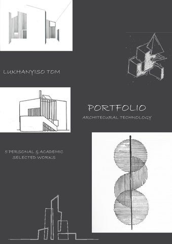
LUKHANYISO TOM
PORTFOLIO ARCHITECURAL TECHNOLOGY
5 PERSONAL & ACADEMIC SELECTED WORKS
Urban agriculture precinct design aims to address the growing need for sustainable and locally sourced food production within the community. By focusing on harvesting food locally instead of relying on imports, the design seeks to benefit the community in several ways. By harnessing the potential of local resources, analyzing the environment, and drawing inspiration from relevant precedent studies, the design seeks to provide a functional and visually appealing space that benefits both the community and the environment. The idea of local food production brings numerous advantages to the community. Firstly, it promotes food security by reducing dependence on external sources and ensuring a steady supply of fresh produce. This not only improves the overall health and wellbeing of the community but also fosters a sense of self-sufficiency and resilience
The design process involved a thorough analysis of the environment and climate within the site, located in Cape Town CPUT. By understan the specific conditions, such as sunlight exposure, wind patterns, The design of the urban agriculture precinct building incorporates several elements to create a functional and visually appealing space..The building's layout is carefully planned to optimize the flow of activities. The ground floor houses the main production area, featuring a variety of cultivation methods such as hydroponics, vertical farming, and rooftop gardens. This allows for efficient use of space and enables different types of crops to be grown simultaneously.
The design process involved a thorough analysis of the environment and climate within the site, located in Cape Town CPUT. By understan the specific conditions, such as sunlight exposure, wind patterns, The design of the urban agriculture precinct building incorporates several elements to create a functional and visually appealing space. in addition, this approach facilitated the construction process and allowed for flexibility in adapting to future expansion or modifications.The steel frame allows for large open spaces without the need for excessive suppo columns, creating a sense of openness and facilitating efficient movement within the building.
nding key e
nding key
orting
Ground Floor
First Floor
A
C
Fire
Unisex toilet
Disabled toilet
workshop bathroom
bedroom woodshop
porch
The f built with has a smok the T to flu at the cham firebo
kitchen
lobby
A
The intent of my design is to have different spaces that interflow functionally with each other by a common element. Spaces can only be created through the use of form, the form of the building must an integrating relationship with its surrounding, which can be means of ordering principles. The combination of different forms and spaces will emphasize each of their significance by means of hierarchy. Exterior spaces should be linked by pathways that serves to gather, measure amd organise a pattern of forms and spaces.
balcony
lounge
Wind open Wind brick maso mort and s align lintel brick DPC a has a sub-c
C
Wall 300x unrei found stand 222x with betw exter cours there wires at ve reinf dens polys insula inter
Throughout this project, I have uti effectively express my workhouse free-flowing and visual manner. It experiment with various layouts a
3D diagrams that truly bring my de workhouse, I can gain a comprehe visual insight into the dimensions, the flow of movement, identify pot aesthetics.
Additionally, the 2D diagrams hav By using two-dimensional plans, s design. These diagrams help me d storage spaces, and common are
Roof Concrete roof tiles fixed to 38x38mm batterns that are spaced at 320mm. roof underlay is installed below the tiling battens and above the top chords of roof structure then underlay membrane is dressed over the tilting batten which is 38x50mm set on edge to prevent ponding at eaves. The roof is a 4 bay Howe truss, at a pitch of 28 and a maximum clear span of 6000mm. Spacing the howe truss. Top chord of 114mm, grade 5 SA Pine. Bottom chord 152mm, grade 5 SA Pine. Web is 114mm, Grade 5 SA Pine. And has a overhang of 600mm. Truss members joined with metal connector plate. Roof trusses are secured and fixed with two strands of 2,4mm diameter galvanized steel wire embedded 300mm into brickwork, the roof truss rest on internal leaf which is a 38x76mm wall plate. 230x30mm SA Pine fascia fixed to rafter ends and 125x80mm seamless aluminium gutter fixed to fascia with downpipe. Roof construction as closed eaves, eaves soffit boards slotted into fascia groove and fixed to 50x50 eaves timber fixed to wall and fascia. 16mm SA Pine quadrant at soffit board edges. 38x38mm SA Pine brandering fixed to the underside of a truss chord at 450mm spacing to support fixed to a gypsum plasterboard ceiling, 6,4mm Gryproc RhinoBoard Plasterboard. For thermal insulation, the roof has a 160mm thick isotherm
eplace
fireplace is masonry with the external wall the cavity behind it. It a masonry flue, with a ke chamber connecting Throat(narrow opening) ue. It has a smoke shelf e bottom of smoke mber. and there is a ox and hearth.
Counter flashing Base flashing
First Floor Slab 1291x193x10mm laminated wood flooring on 30 screed, on a 170mm concrete slab resting on inner leaf of cavity wall. A Gyroc ceiling board is fixed to 38x38mm branding batterns which are attached to the underside of concrete slab
dow Opening (window ning is 1100h x 1500w) dow placed built into kwork on inner leaf on onry wall, deep bed of tar required for soldier stretcher courses to , insulated cavity steel l supporting the kwork, and stepped above lintel. Opening a brick on edge window cill
Stairs Stairs are L shaped stairs, makes a right angled turn in the path of travel. Stairs constructed of concrete, have solid risers and treads, horizontal distance between supports is 6000mm, therefore slab thickness will be 231mm. with a ceiling height of 2100mm, the height of handrail is 1000 and the vertical height of stairs is 3100mm
700mm rectangular inforced concrete dation that supports a dard size brick of 106x73 masonry wall a 50mm cavity ween the internal and rnal leaf. In every 4th se of the external leaf e is slight, welded steel s built into brickcourse ertical centres for orcement. 30mm high ity extruded styrene closed cell ation boards fixed to rnal skin of brickwork
This drawing illustrate how the rafter goes through the leaf of the wall, it is resting on a wallplate. 38x70mm grade 5 SA purlins fixed on rafters, above purlins is a metal roof sheeting, to guarantee water does not go in the space were the roof sheeting meet the brick wall, a base flashing has been fixed on the roof sheet against the external leaf and a counter flashing embedded into the external of the masonry of the cavity wall, going horizontally down along the wall and sits over the base flashing to ensure water doesn’t slip behind the base flashing
flooring 1291x193x10mm laminated wood flooring on 30 screed, on 140 concrete surface bed, underneath there is a 30mm isoboard insulation, that also runs vertically along inner walls to the top of the foundation, under isoboard insulation there is Damp proof membrane which lies on top of 50mm sand binding, on two 150mm compacted filling layers done mechanically and earth fill underneath.
STRIP SECTION A-A SCALE 1:20
This drawing illustrate roof underlay is installed below the tiling battens then dressed over the tilting batten which is set on edge, this helps to prevent ponding at eaves. It reduces excessive pressure build up inside roof due to wind gusts, as well as an impervious barrier for wind driven rain and dust, basically prevent the risk of leaks, mold and water damage from entering the building
7100mm
2800mm
Wallplate Level
2800mm
First Floor Level
Ground Floor Level
ELEVATION SCALE 1:20
ERF 10162
ilized various techniques such as sketching, 3D diagrams, and 2D diagrams to e design. Sketching has allowed me to capture my initial ideas and concepts in a has served as a starting point for me to explore different design possibilities and nd arrangements.
ERF 10156
ERF 10155
ERF 10164
esign to life. By creating realistic three-dimensional representations of the ensive understanding of how the space will look and feel. These diagrams provide a , proportions, and spatial relationships within the design. They enable me to analyze tential issues, and make necessary adjustments to ensure optimal functionality and
ve played a crucial role in defining the organization of spaces within the workhouse. sections, and elevations, I am able to meticulously outline every aspect of the determine the placement of different functional zones, such as the work areas, eas
ERF 10163
NORTH WESTERLY WIND/RAIN
ERF 10154 SUNRISE IN THE EAST
SUN SET IN THE WEST
ERF 10166
SOUTH EASTERLY WIND/RAIN
ERF 10173
ERF 10172
ERF 10171
Site Analysis Scale 1:200
Site Development Plan Scale 1:200
GREEN
B
Grass laye 20mm fixe PermaSea Compound outlet so t
BALUS
10mm Dia galvanised
CURTA
CW 50 S gasket se 2000mm. 15000mm
CEILIN A
SUSPE
600X600M slab and
INTERI
Timber co fixed to 65
FOUN
380X380m 1520x152
B
A
Ceiling ty edge of th
Working on a group assignment project with Lwando Hasheni was an enriching experience that significantly enhanced my collaborative skills and expanded my design capabilities. The project required seamless teamwork, pushing me to effectively communicate and coordinate ideas with Lwando and other team members. Through this collaborative effort, I not only gained a deeper understanding of working in a team but also discovered the importance of diverse perspectives in achieving a well-rounded design. Moreover, the project provided a platform for me to refine both my 2D and 3D sketching skills. The iterative process of sketching and refining concepts helped me visualize ideas more precisely and communicate them effectively. Particularly, the emphasis on 3D model making was a revelation. It not only allowed us to visually grasp spatial relationships but also provided a tangible sense of the design, enabling us to feel the space we were creating. This realization underscored the transformative power of 3D modeling in the design process, emphasizing the importance of both visual and tactile understanding in creating meaningful and impactful designs. Our group assignment project focused on the design of a concrete school building with a unique feature—an innovative roof garden. This particular aspect not only challenged our team to think creatively about educational spaces but also expanded my knowledge on the intricacies of designing and implementing roof gardens. As we delved into the project, I had the opportunity to explore detailed sections related to the integration of a functional and aesthetically pleasing green space atop the building. Understanding the structural considerations, drainage systems, and plant selection for the roof garden provided valuable insights into sustainable and eco-friendly architectural practices. This aspect of the project not only enhanced my technical understanding of architectural design but also deepened my appreciation for the potential impact of thoughtful design choices on the environment and the overall functionality of a space.
N ROOF AND RAINWATER GOODS
er fixed to 80mm Growing medium, fixed to 5mm Geotextile filter fabric fixed to ed to permaSEAL@20P Green Roof Drainage and Storage Membrane fixed to 25mm al@Root Barrier, fixed 25mm insulation board, fixed to 10mm MB2K waterproofing d, fixed to 30 screed with corner fillet. At each plant container there is a water drainage hat rainwater can be discharged with siphonic roof outlets that is a 50mm downpipe
+18100
STRADE DETAIL
acountersunk MS. Black Bolt connecting 150x38mm SA. Pine member 50x50mm d metal posts which is fixed to balcony slab with M12 anchor bolts
AIN WALL
tick system curtain walls with double glazing with thermal brake. Glass fixed with silicone ealants to 100mm Mullion in in size, double glazing frame and distance centre-to-centre is . The transom size is 65, transom length is at 2000mm and transom distance is at m
NG
ype is jointless at a suspended depth of hangers at 500mm and 1200mm distance centre. At the he Plasterboard, Connected to curtain wall is 30x30mm plaster perimeter edge trim
ENDED FLOOR
MM Tile on 30mm screed on 360mm grade 10 in-situ reinforced concrete suspended floor 630mm edge beam
+14300
IOR WALLS
onstructed dry wall with 65x60mm top plate fixed to 65x50 studs with 400mm spacing, 5x50mm wall plate, fixed to 12mm gympsum on both sides
NDATION
mm reinforced concrete column fixed and Plastered to reinforced grade 10 in-situ 20mm concrete pad foundation
+10500
NGL
CIB competition poster, our group's dynamic competition poster is a vibrant call to action aimed at fostering sustainability and boosting the local economy in the town of Tshwane, Pretoria. Designed to engage and inspire the community, the competition invites participants to propose innovative and ecofriendly solutions tailored to the town's unique needs. By encouraging sustainable practices and green initiatives, we aimed to create a positive impact on both the environment and the economy, fostering a sense of community involvement and shared responsibility for a greener, more prosperous Tshwane.
university assignment aimed at enhancing my analytical skills, I chose to explore the intricate relationship between sketching, technology, and spatial design by focusing on a staircase. Employing both traditional sketching techniques and digital tools, I dissected the staircase's form, considering its aesthetic and functional aspects. This interdisciplinary approach not only deepened my understanding of spatial structures but also showcased the symbiotic potential of merging artistic expression with technological analysis in the realm of architectural studies.
THANK YOU FOR LOOKING AT MY PORTFOLIO
CONTACT NUMBER: 061 706 4220 EMAIL: LUKHATOM@GMAIL.COM