PASINI LUDOVICA
ludovicapasini@gmail.com
T: +39 347 732 2708
Self portrait

Acrylic on canvas, 2022
EDUCATION
2017 - 2022
BACHELOR OF ARCHITECTURAL SCIENCE
Toronto Metropolitan University, Toronto, ON (formerly Ryerson University, name changed April 2022)
Dean’s List Academic Years 2020-2021 and 2021-2022
2023- ONGOING MASTER IN YACHT DESIGN, XXII EDITION
Politecnico di Milano, Milan, Italy
EXPERIENCE
SEP 2022 - DEC 2022
EDWARD WILLIAMS ARCHITECTS, London, UK
Aided in technical drawings for both private and commercial buildings, including structural redesign.
NOV 2021 - JUNE 2022 RESEARCH ASSISTANT, with professor George Kapelos from Ryerson University
Assisting with the creation and development of an architectural database of architects who entered the 1958 Toronto City Hall and Square competition, Faculty of Engineering and Architectural Science at Ryerson University
MAY 2021 - AUG 2021 STUDIO ARCHITETTI MAR, Venice, IT
Assisted on various Bonus110 projects including 3D modeling and site inspections
Support tasks within Architecture and Landscape Architecture scopes
ACHIEVEMENTS
MAY 2022
DEAN’S LIST, Faculty of Engineering and Architectural Science at Ryerson University
Achieved a minimum GPA of 3.5 in the academic year of 2021-2022
DEC 2021 CHOSEN FOR YEAR END SHOW 2021, Faculty of Architectural Science at Ryerson University
NIA Center for the Arts project was chosen as one of three best projects of the semester of 2021
MAY 2021 DEAN’S LIST, Faculty of Engineering and Architectural Science at Ryerson University
Achieved a minimum GPA of 3.5 in the academic year of 2021-2022
SKILLS
Maxsurf
Sketchup
Rhinoceros
Revit
AutoCAD
Photoshop
Enscape
Vray
Illustrator
InDesign
MAY 2019 - AUG 2019
STEFANO DOMENICI ARCHITECTS, Montréal, CA
Architectural programming, Design Development,3D modeling, Presentations, Site Inspections
LANGUAGES
English
Italian
E:
3D 2D
CONTENTS 01 THE MODDED HOUSE 02 NIA CENTER FOR THE ARTS - PHASE I 03 NIA CENTER FOR THE ARTS - PHASE II 04 MURB - MULTI UNIT RESIDENTIAL BUILDING 05 THE RESILIENT LIBRARY ARCHITETCURE 06 SEA FEVER - SAILING YACHT 07 SKETCHES YACHT DESIGN
Location Semester
Professor Programs
THE MODDED HOUSE
ND, Movable and adaptable house Fall 2021, Fourth Year
Kevin Stelzer
Rhino, Adobe Illustrator, Photoshop, V-Ray
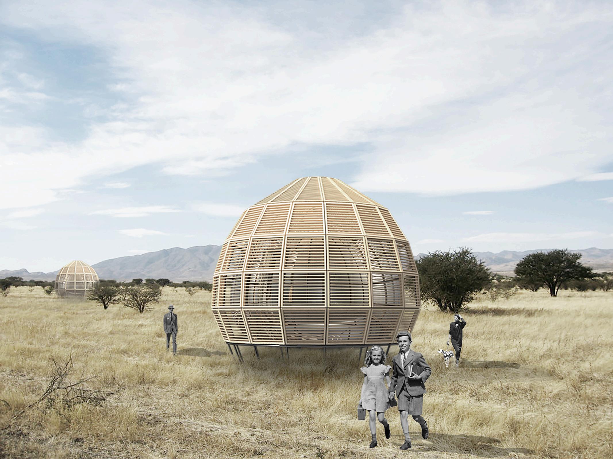
The modded house is based on the idea of a movable and adaptable house that can be mounted and dismounted in most locations around the world. It consists of an inner inflatable component ‘the gut and its exterior structure, which keeps the gut tied to the ground and offers weather protection.
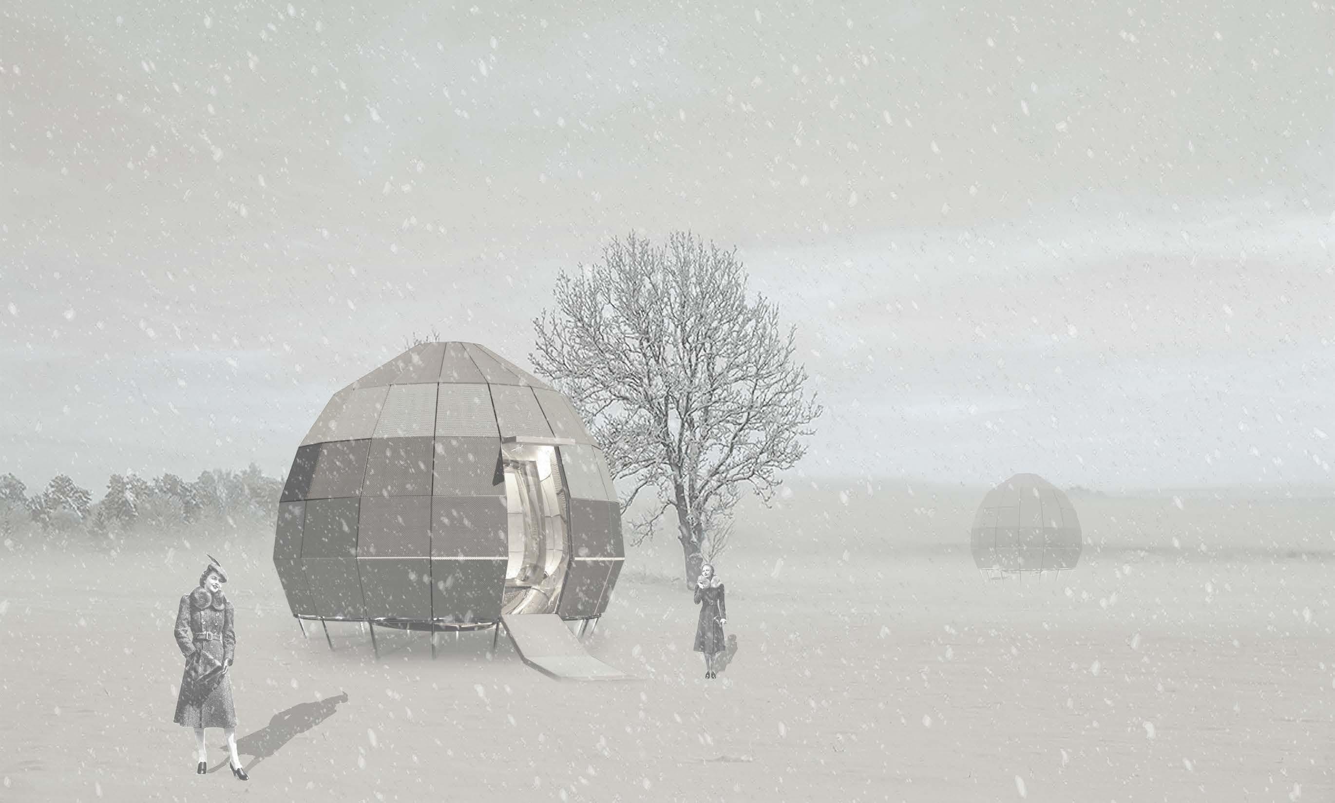
The gut is a customizable space that eliminates the need for furniture. The high-tech building material transforms to accommodate the user’s needs in a laying, seating and standing position.
The exterior structure aims on the conservation, efficiency and optimization of energy through the use of interchangeable panels such as solar, window, and louver panels.
01


A A B B C C PLAN + COMPOSITION DIAGRAM | THE GUT IS KEPT IN ITS INFLATED FORM THROUGH A PRESSURIZING FAN, AND THE RECYCLED WARM AIR IS USED TO HEAT THE INTERIOR LIVING SPACE. HELICAL ANCHOR ALLOWING FOR THE STRUCTURE TO ADAPT TO ANY TYPE OF UNEVEN SOIL DISMOUNTABLE ALUMINUM STRUCTURE INFLATABLE DOUBLE LAYERED GUT HIGH-TECH BUILDING MATERIAL INTERCHANGEABLE PANELS DIFFERENT PANELS CAN BE CHOSEN BASED ON THE WEATHER OF THE LOCATION
PANEL COMPOSITION
MITREX SOLAR CLADDING PANEL
3‘‘ ALUMINUM HONEY COMB
BLACK SHEET
SOLAR CELLS
MITREX CLADDING
TOP PANEL SUPPORTER
BOLTS
BOTTOM PANEL SUPPORTER
METAL CLIP-ON CONNECTOR
ALUMINUM ROD
AXONOMETRIC
CUSTOMIZABLE INTERIORS ACCOMMODATE THE USER’S NEEDS IN A SEATING (AA), STANDING (BB) AND LAYING (CC) POSITION

AA BB CC RAIN HARVESTING SYSTEM GREY WATER COLLECTOR WASTE WATER COLLECTOR HELICAL ANCHOR SOLAR POWER COLLECTOR ADAPTABLE FURNITURE MULTIPURPOSE SPACE WINDOW PANEL WATER TANK KITCHEN POD
Location
Semester Professor Programs
NIA CENTER FOR THE ARTS PHASE I
1725 Englinton Ave W, Toronto, ON Fall 2020, Third Year
Carlo Parente
Revit, Adobe Illustrator, Photoshop, Enscape
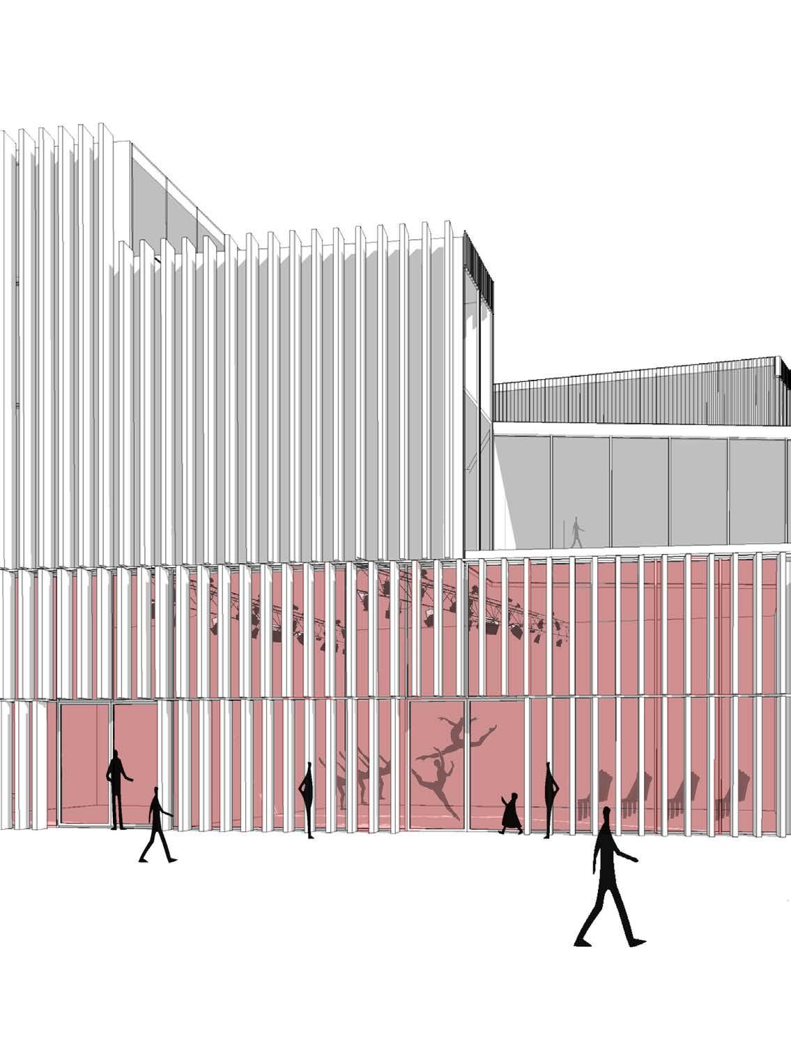
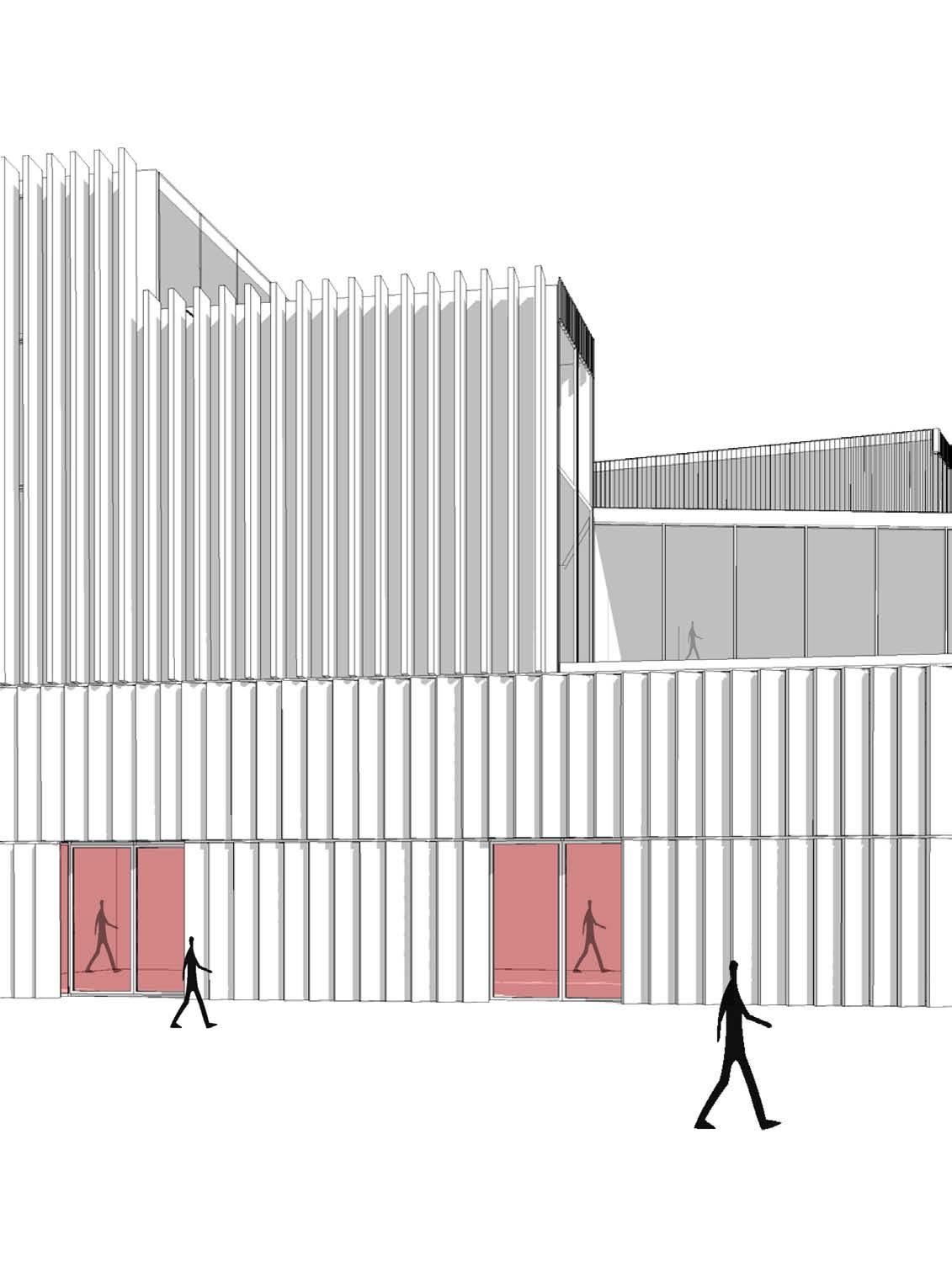
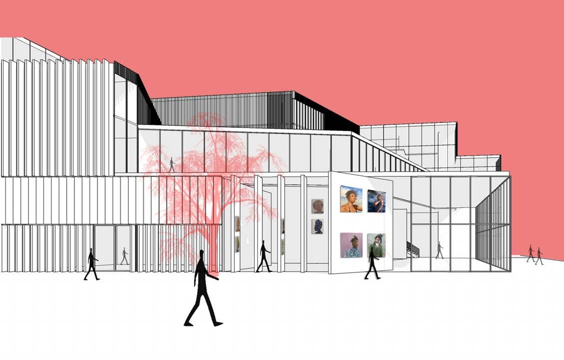
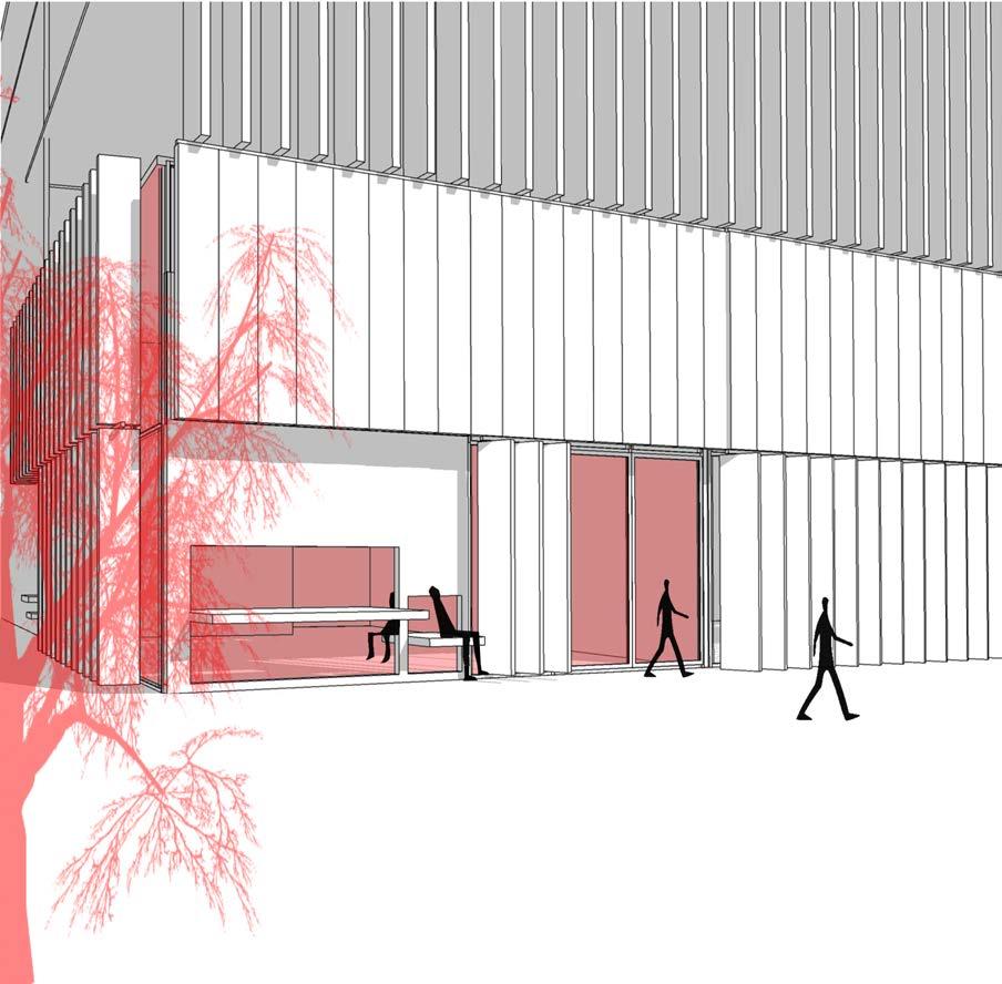
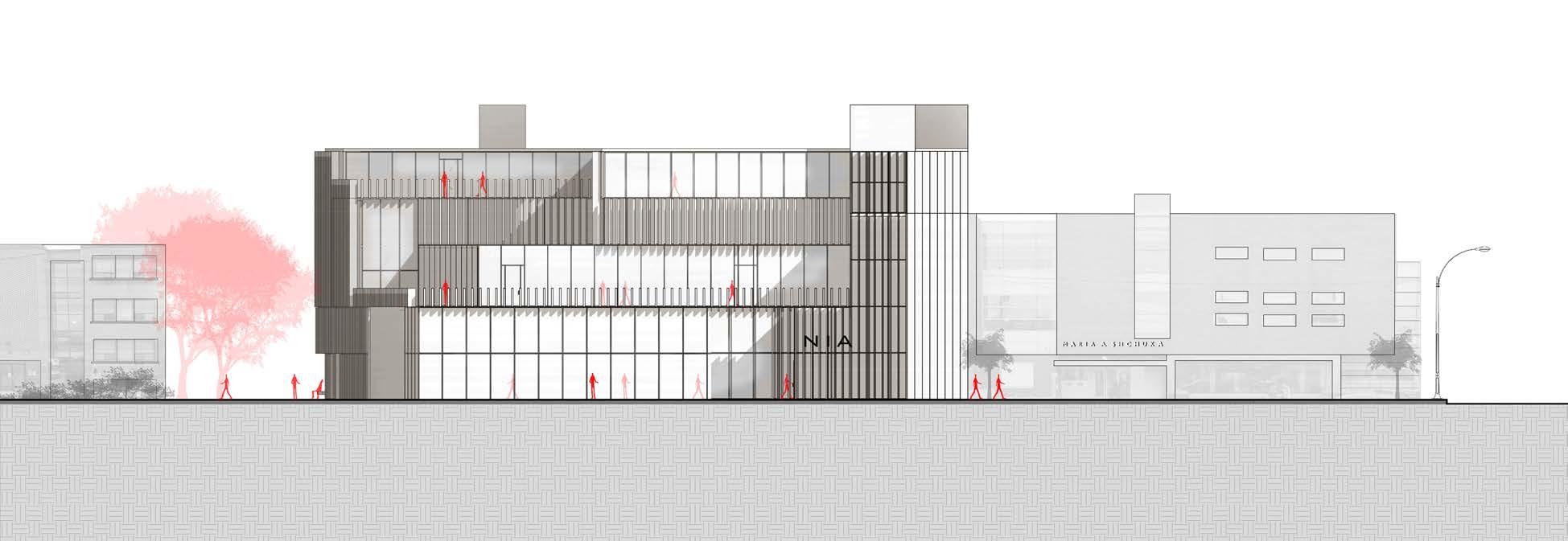
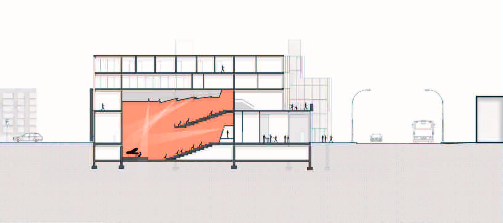
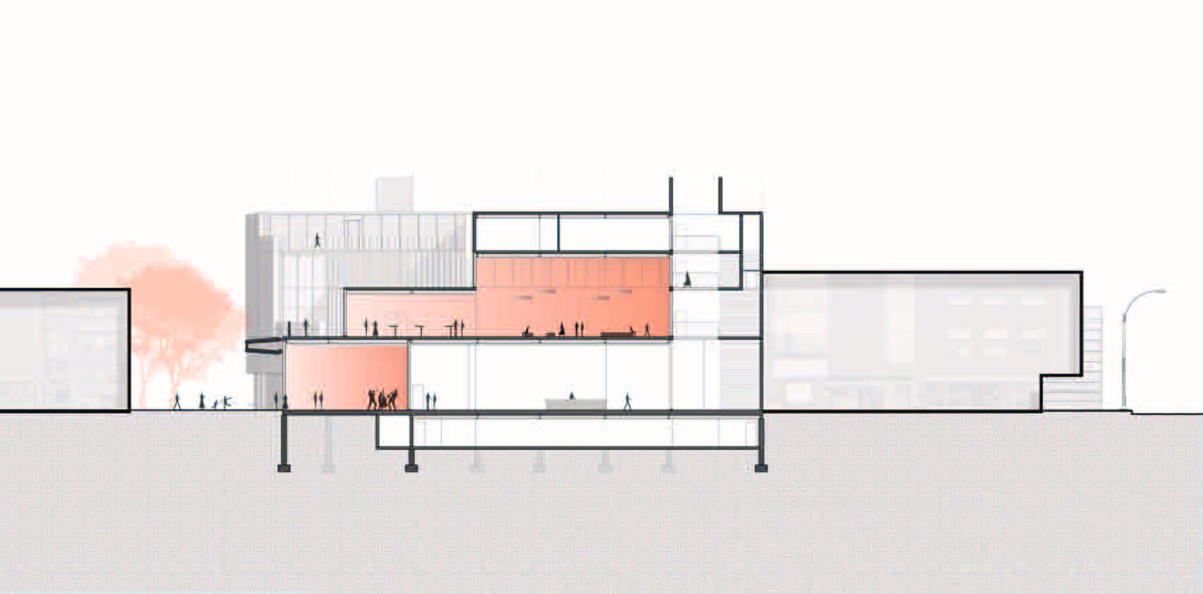
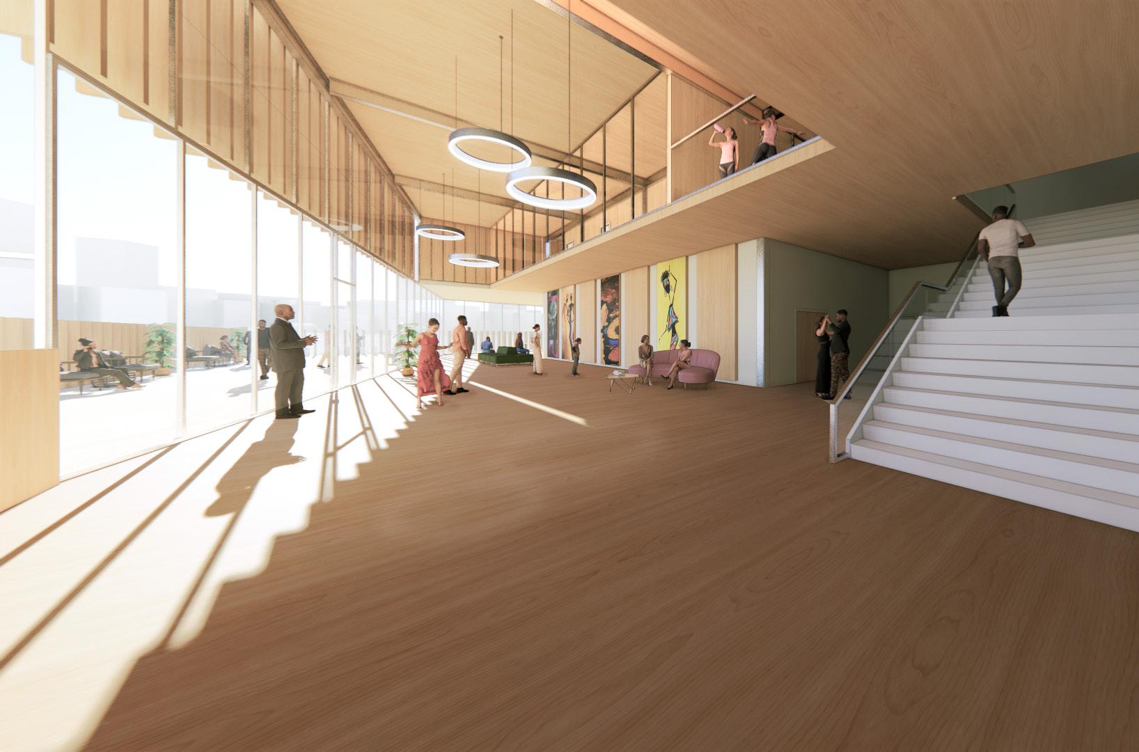
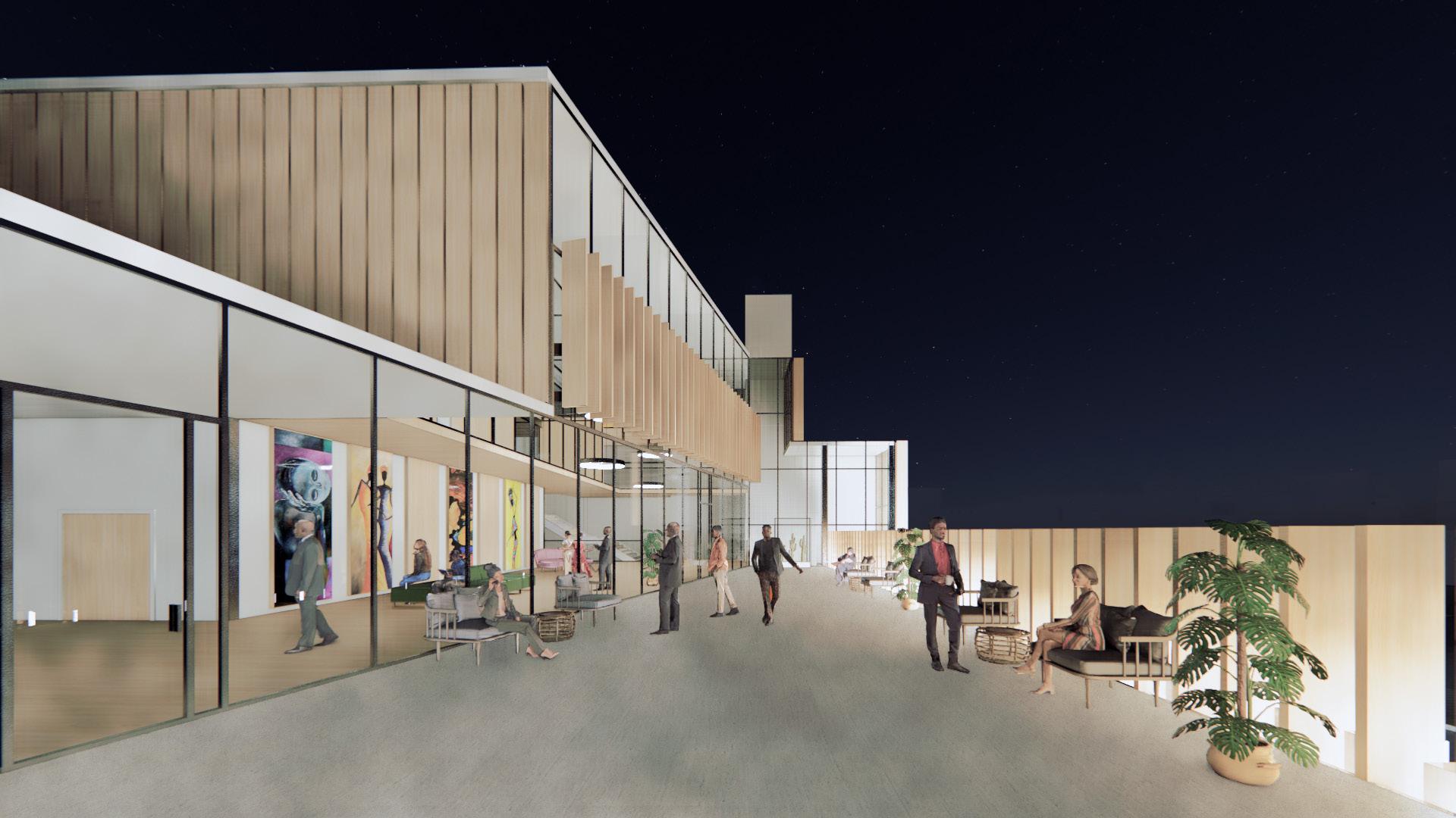
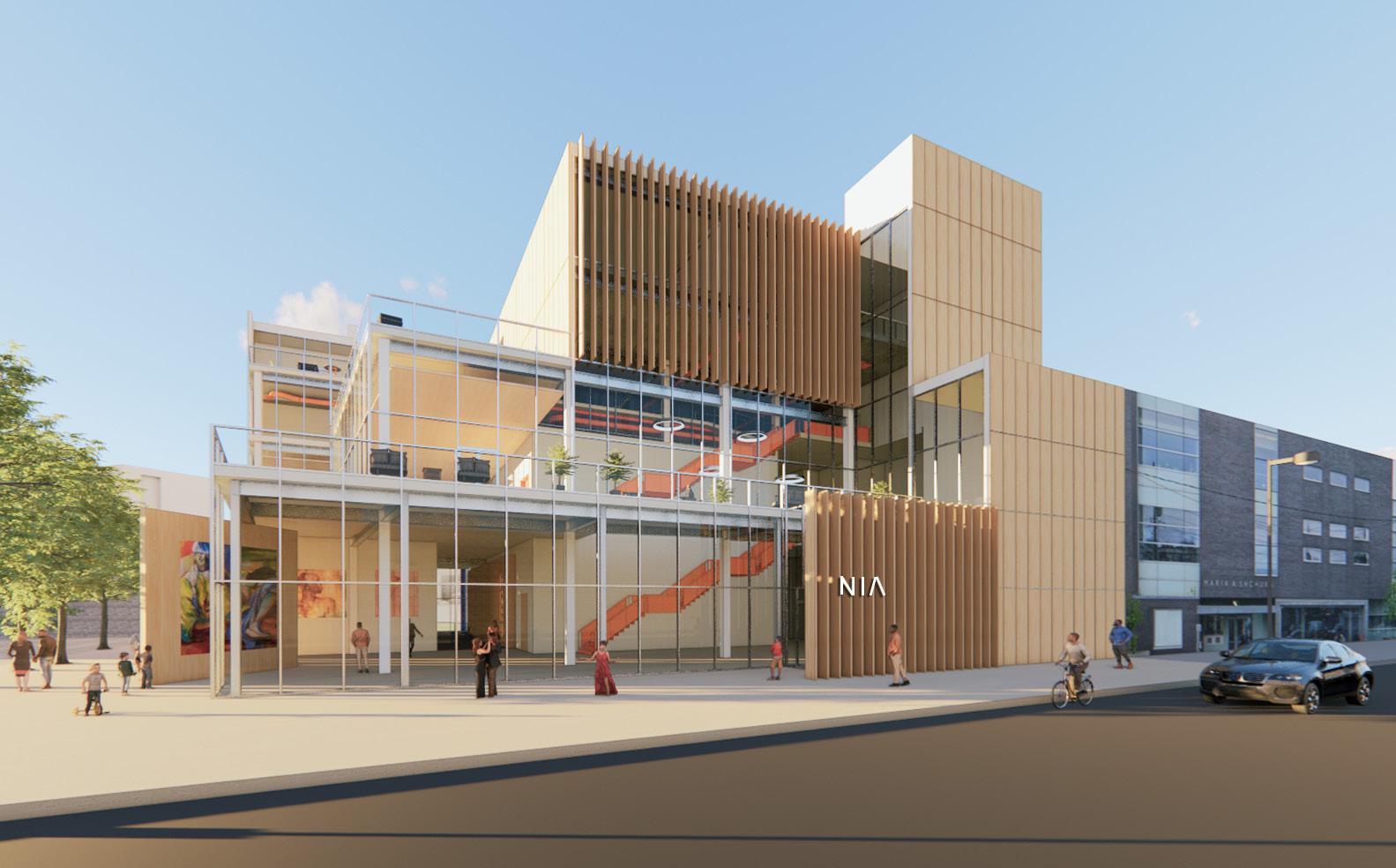
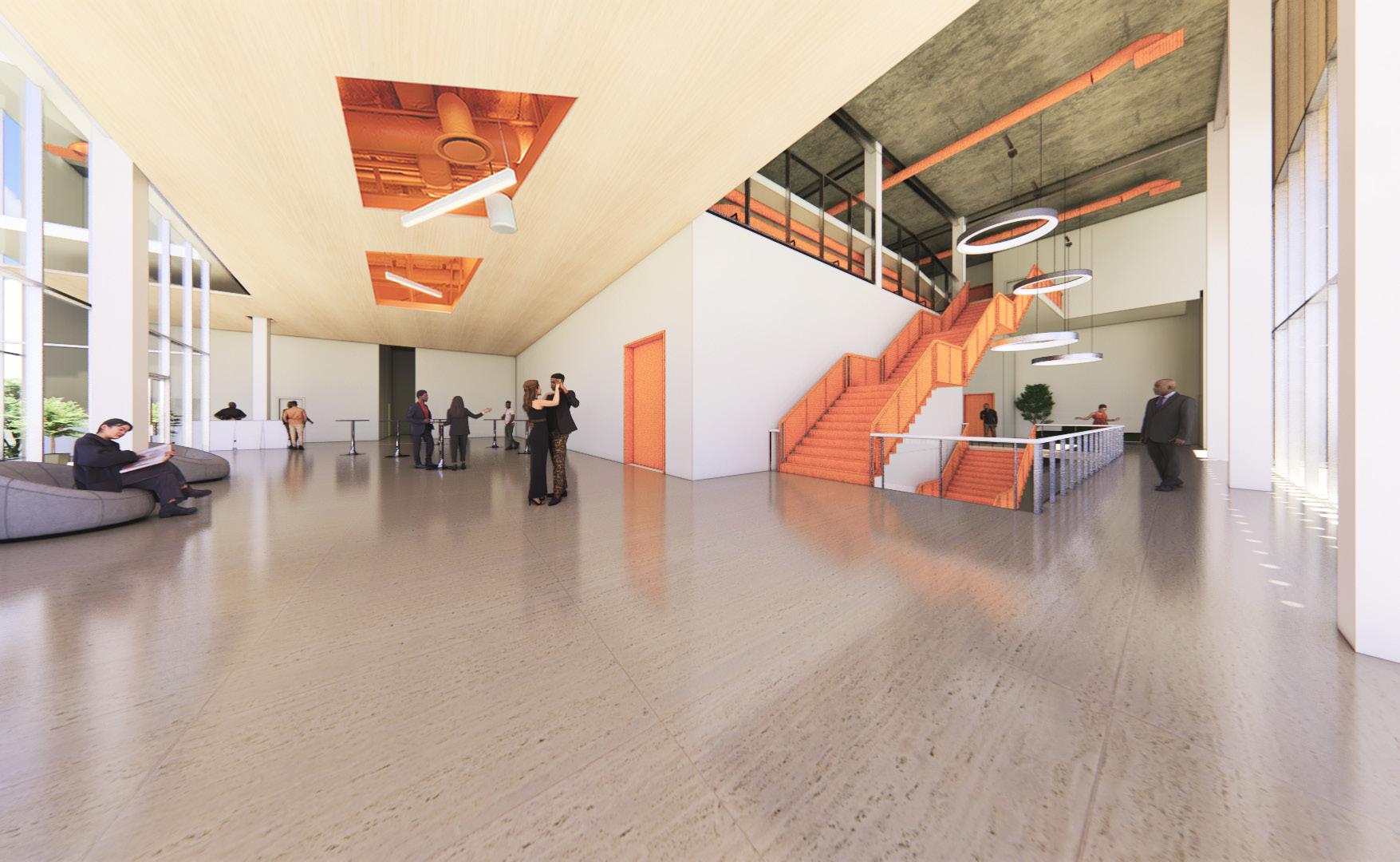
The Nia center for the arts is located in Little Jamaica in Toronto, Canada. The project aims to enhance the cultural and social aspects of the neighborhood by responding both visually and physically to its surrounding context. Vertical rotating composite wood fins cover the building mimicking the overall vertical rhythm of the neighborhood, while engaging with the community through its dynamic facade.
Chosen by Ryerson University for YES2021 (Year End Show 2021)
02
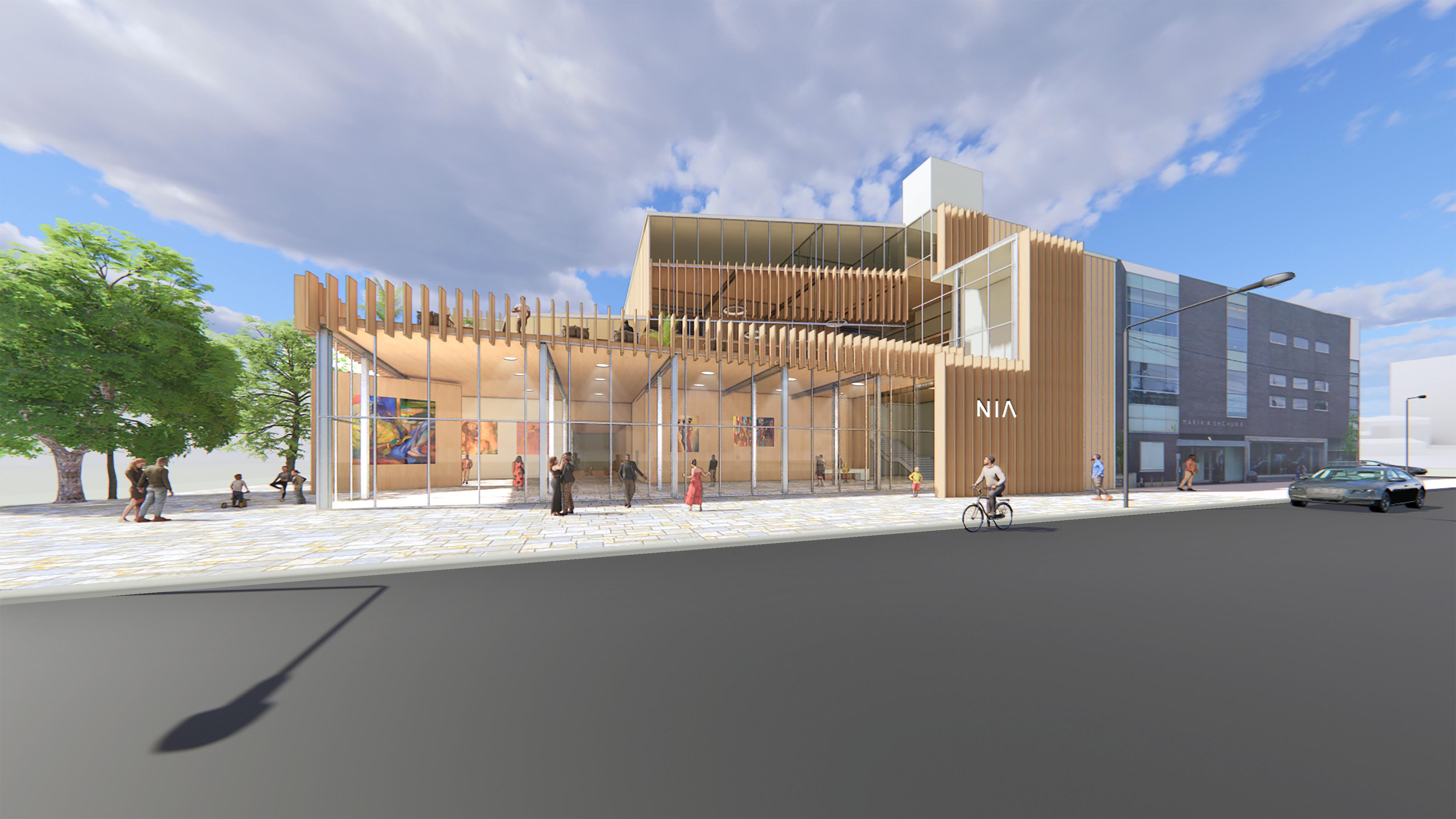
regulation of heat absorption keeping solar radiation out during the cooling seasons, and allows for privacy
DESIGN PHASE SKETCHES
The system allows for the structure to absorb heat during the winter months, and for natural light to penetrate reducing the building’s fuel use
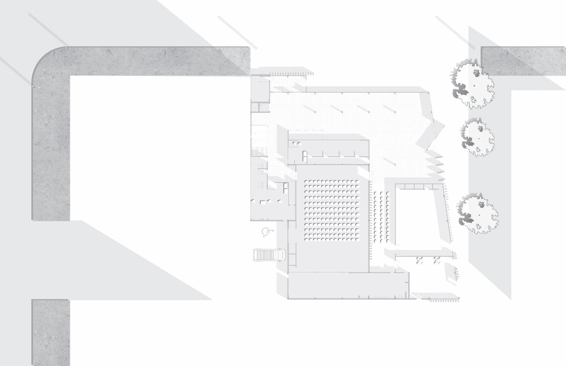



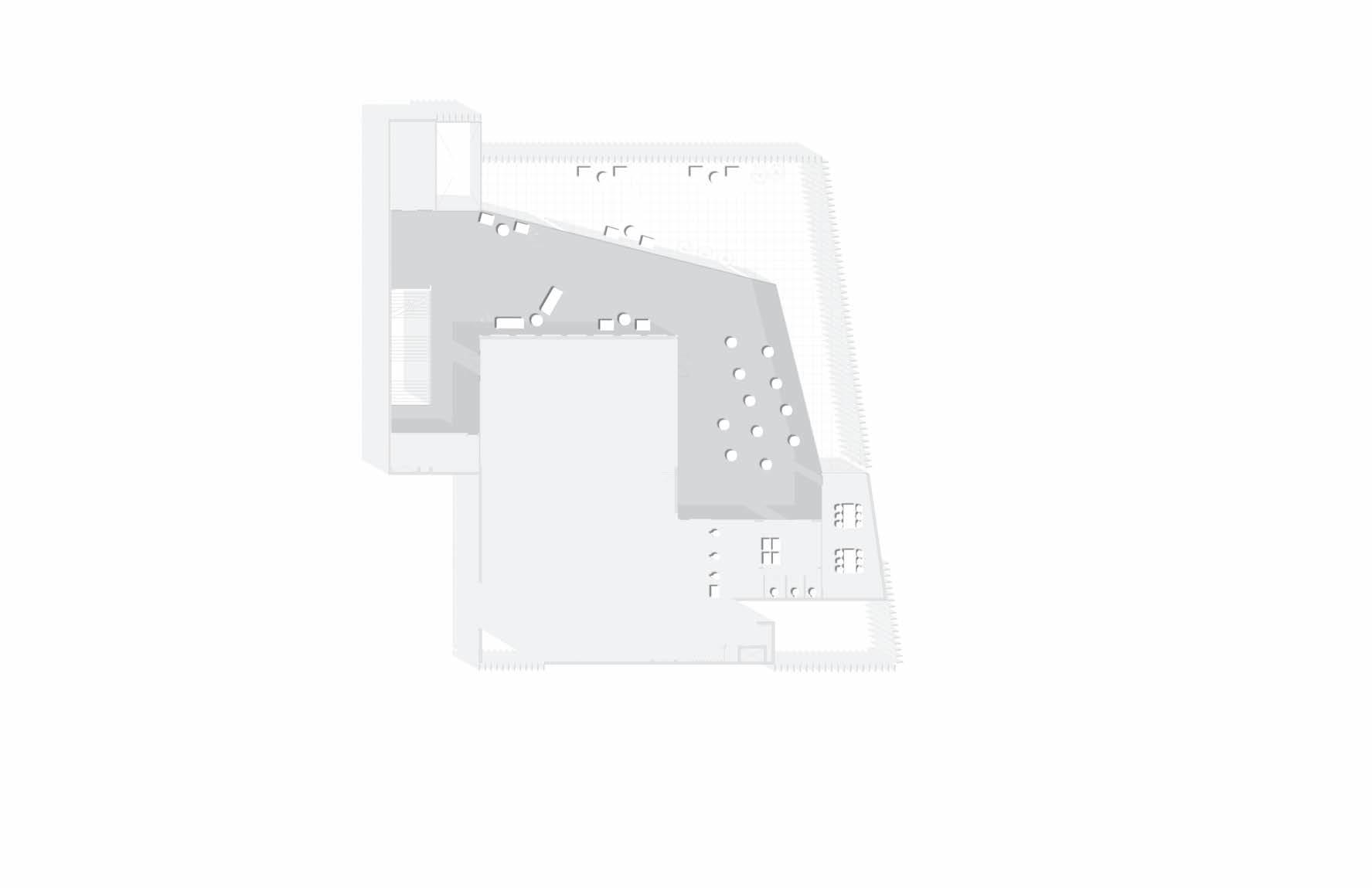

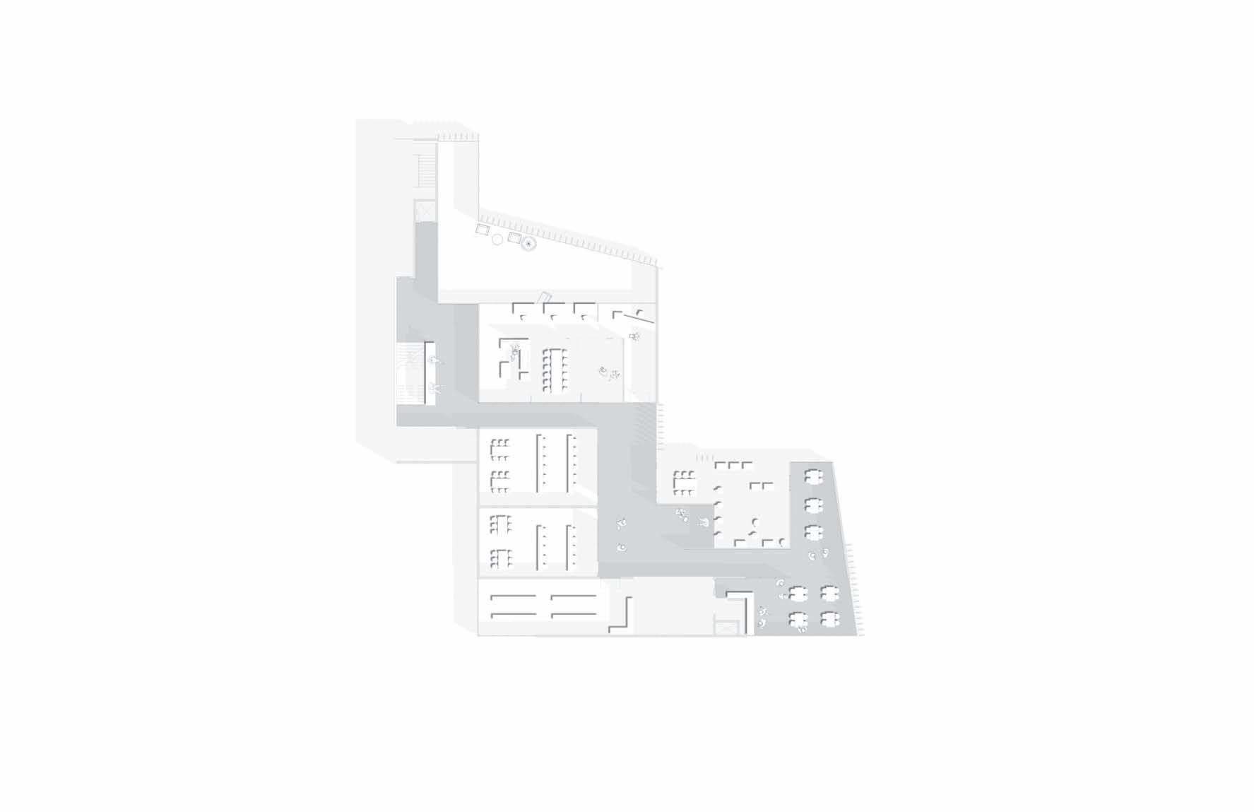
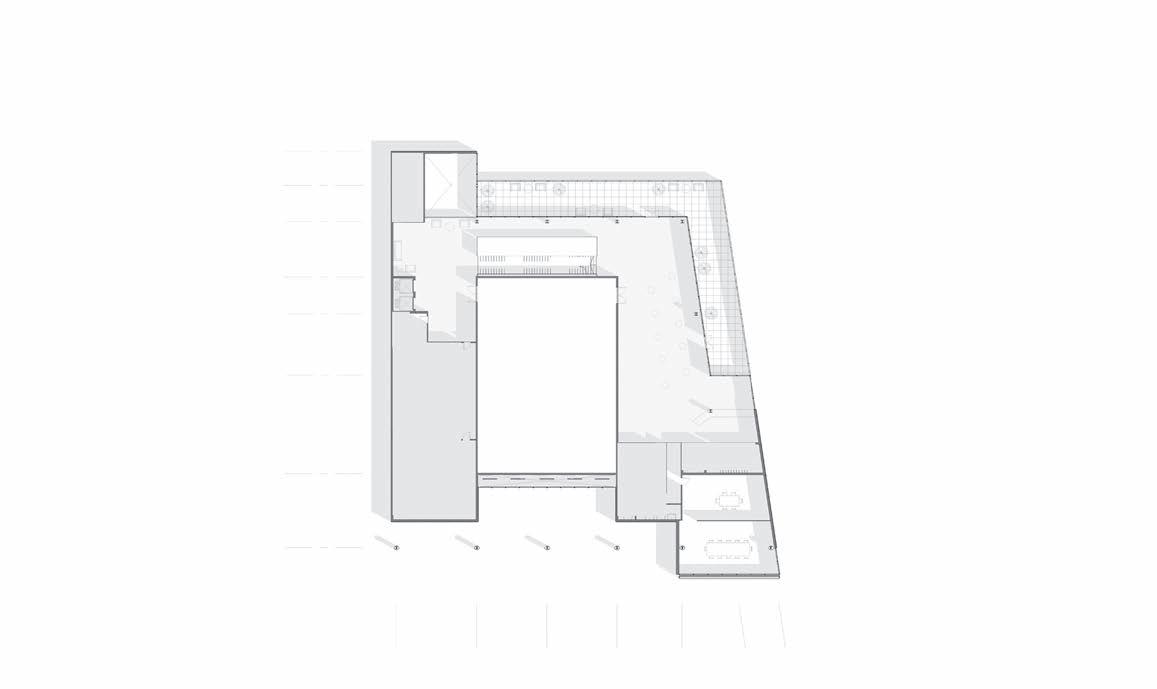
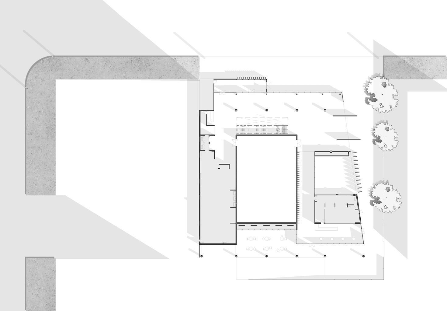
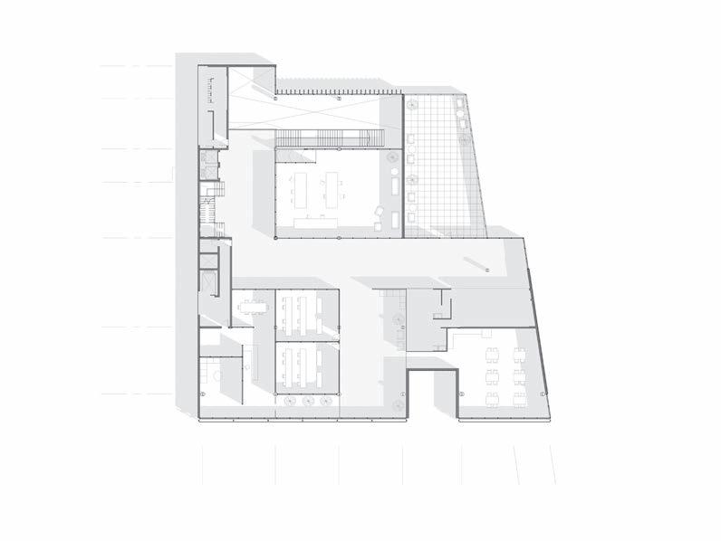
B B A A 4. 3. 2. 1. 5. 6. 6. 7. 8. 9. 10. 12. 11. 13. 1. 7. 6. 2. 3. 4. 5. 8. 9. 9. 10. 11. 12. 5. 4. 1. 3. 6. 9. 8. 7. 2. Second floor: 1. Pre-event lounge 2. Terrace 3. Open event rentable space 4. Auditorium 5. Catering kitchen 6. WC 7. Janitor room 8. Public meeting room 9. Media tech room Third floor: 1. Circulation - lounge 2. Guest studios 3. Rehearsal rooms 4. Recording studio 5. Recording booth 6. WC 7. Janitor room 8. Workshop 9. Meeting room 10. Terrace Ground floor: 1. Cafe’ 2. Performance space 3. Loading 4. Auditorium 5. Changing rooms 6. WC 7. Janitor room 8. Security 9. Coat check 10. Entrance hall 11. Vestibule 12. Art gallery
Location Partner Professor Programs 03
NIA CENTER FOR THE ARTS PHASE II
Semester Winter 2021, Third Year
1725 Englinton Ave W, Toronto, ON Diego Moreno Garth Iver Norbraten Revit, Adobe Illustrator, Photoshop, Enscape
Nia center II is the evolution of the previous iteration. During this semester students were challenged to advance their projects and develop them to a constructible level. Attention was given to technical drawing language and the design of architectural details. All details were designed in accordance with the OBC (Ontario Building Code), and the necessities of Canadian weather.
1. VERTICAL MULLION
2. ROTATING COMPOSITE WOOD FIN
3. SEALED GLASS UNIT
4. ROTATING MECHANISM

5. HORIZONTAL RAIL
6. FIN METAL FRAME
7. OPERABLE WINDOW WALL
8. STEEL STRUCTURAL COLUMN
9. OPERABLE WINDOW WALL MECHANISM
10. 400X300mm STEEL BEAM
11. FIN METAL CONNECTOR TO STRUCTURE
12. STEEL ROOF DECK
13. VAPOUR BARRIER
14. CAST-IN-PLACE CONCRETE FLOOR SLAB
15. RIGID INSULATION
16. BATT INSULATION
17. TRAVERTINE TERRACE FINISH
18. GLASS RAILING
19. REGULAR WINDOW WALL
EGLINTON AVE 2 4 A B H G D F 6 C 5 E 4229 2 3986 830 725 7250 673 626 406 526 0 4260 9 1616 1791 1013 7 A-200 01 A-201 02 A-400 02 4. 5. 6. 7. 8. 7 5 6 39947 7250 6731 6268 4149 7188 21 708 16 927 01 A-303 02 A-308 02 A-201 01 A-200 1. 2. 3. 4. 5. 6. 7. 8. 9. 10. 11. 2 4 A B H G D F C E 42 288 78 80 67 07 10 361 39 22 59 29 38 45 36 45 39996 8300 7250 7250 6731 10466 8950 25126 21 708 20 769 6 02 A-307 01 A-302 02 A-201 01 A-200 top left: second and third floor bottom left: ground floor LEV 2 6000 100 0 10 0 273 1 950 950 197 134 417 3636 4138 30 40 0 19 5 18 0 1073 40 0 6 7 132 11 6 2 18 16 15 14 12 10 5 19 7 9
4 13 17 Detail A - Axonometric Detail B - Axonometric
Location Semester Professor Programs
81 Dundas St E, Toronto, ON Fall 2021, Fourth Year
Kevin Stelzer
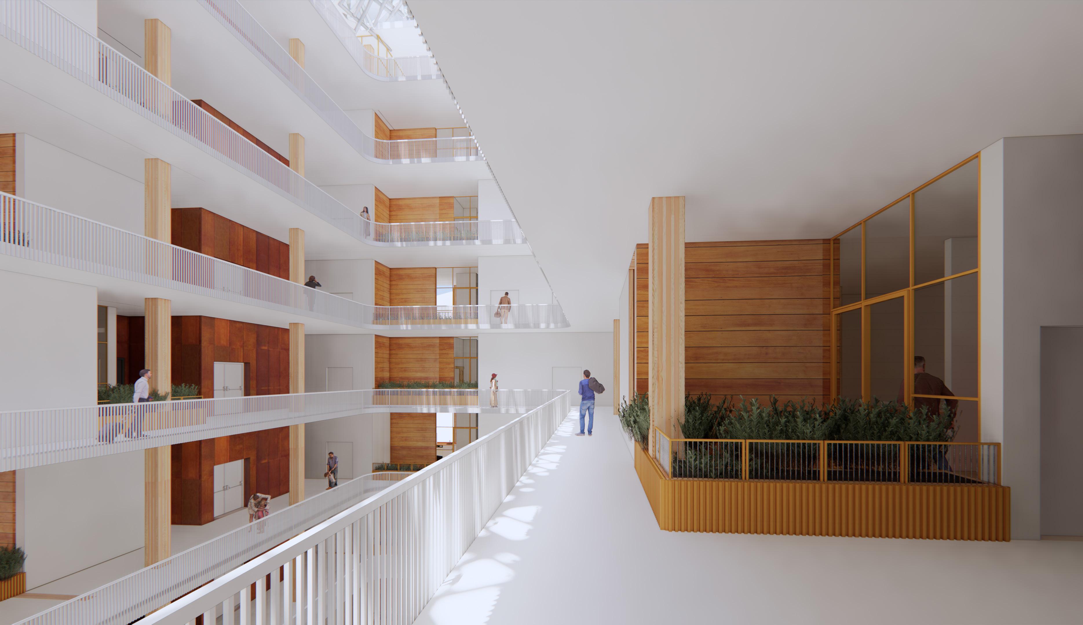
This project is a design of a zero carbon multi-unit residential building. The focus of the project was on the development of a comprehensive design while functional organization, system integration, fire safety and high-performance enclosure design to support zero carbon certification.
MURB MULTI UNIT RESIDENTIAL
BUILDING
04
Revit, AutoCAD, Adobe Illustrator, Photoshop, Enscape
left: conceptual diagram


right: floor 2,4,6,8,10,12

1 3 5907 5015 6800 6800 2 5 6 7 5015 5907 A B C 4 E F G H Slope 15% UP 85 m² Loading 28 m² Garbage BOND STREET DUNDAS STREET ope 7% Slope 7% Outdoor seating 170 m² Cafe/Min market Coat-check m² Electrical closet 78 m² Retail Security Staff offices D 612 0 612 0 612 0 612 0 612 0 612 0 612 0 DWREF REF.DW REF.DW DWREF. R EF DW REF. DW REF. REF. DW REF. DW 1 3 2 5 6 7 A B C 4 E F 590 5015 6800 680 5015 590 G H 612 0 612 0 612 0 612 0 612 0 612 0 612 0 83 m² Unit 5 84 m² Unit UP 83 m² Unit 9 UP Elect cal closet 84 m² Unit 10 Water pump Jan to room W/D W/D W/D W/D W/D 79 m² Unit 8 W/D W/D W/D W/D W/D D Secure storage room 81 m² Unit 79 m² Unit 79 m² Unit 81 m² Unit 79 m² Unit A Shaf EF DW DWREF. REF. DW DWREF. REF.DW DWREF. REF. DW REF.DW 1 3 2 5 6 7 A B C 4 E F G H W/D W/D D 612 0 612 0 612 0 612 0 612 0 612 0 612 0 5907 501 6800 6800 501 5907 W/D W/D 80 m² Unit 11 60 m² Unit 12 100 m² Unit 13 82 m² Unit 14 82 m² Unit 19 83 m² Unit 20 83 m² Unit 15 80 m² Unit 16 60 m² Unit 17 100 m² Unit 18 Secure storage room Elect cal closet ir shaf Water pump Jan to room top
bottom
top
bottom
left: ground floor
right: floor 3,5,7,9,11
PROPOSED UNIT-A


PROPOSED UNIT-B

+ 49.00 ROOF + 45.00 LEV 12 + 41.00 LEV 11 + 37.00 LEV 10 + 17.00 LEV 5 + 13.00 LEV 4 W/D REF DW W/D
Location
Semester
Professor Programs
THE RESILIENT LIBRARY HERITAGE PROJECT
350 Victoria St, Toronto, ON Winter 2022, Fourth Year
Joey Giaimo
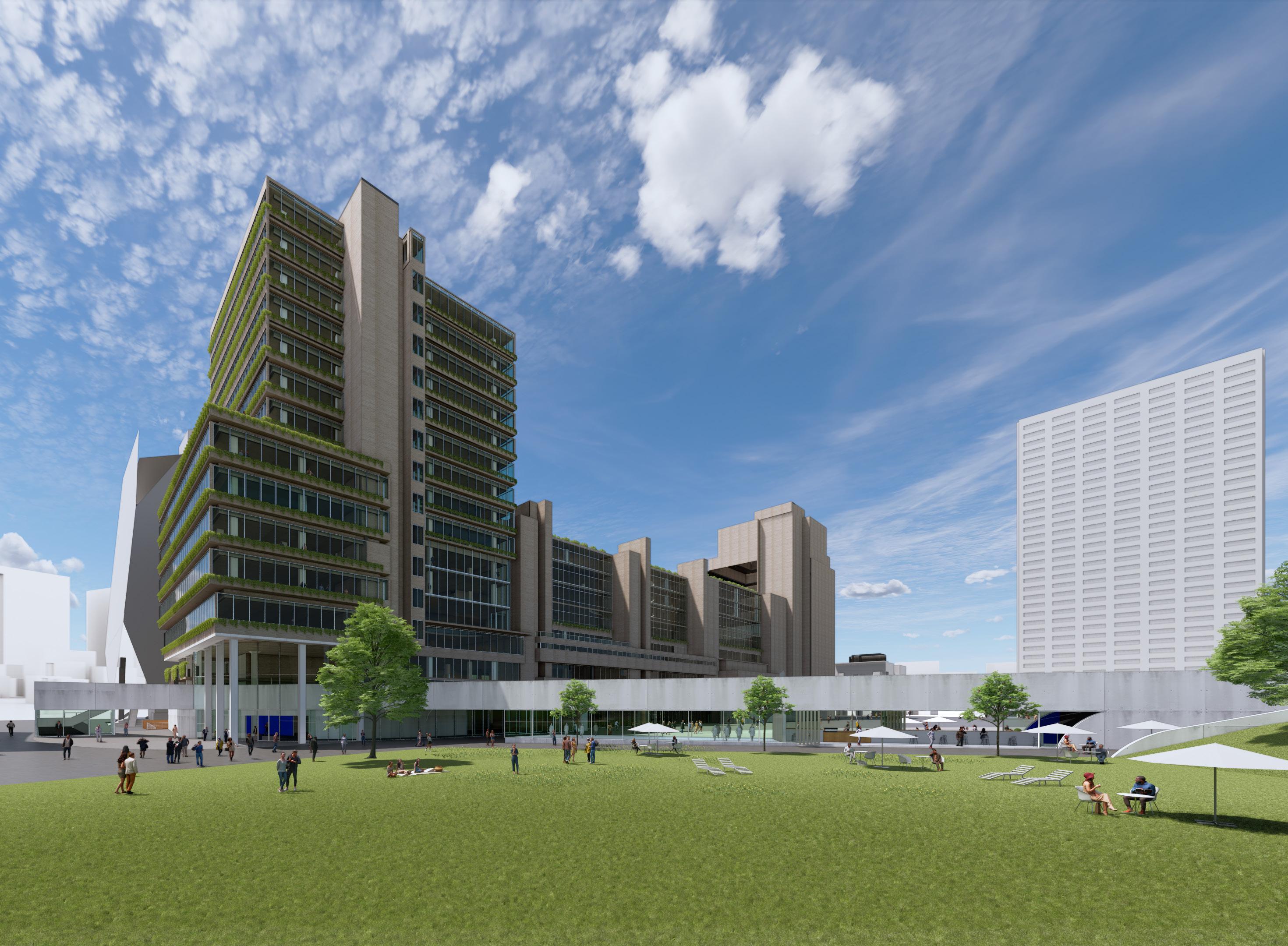
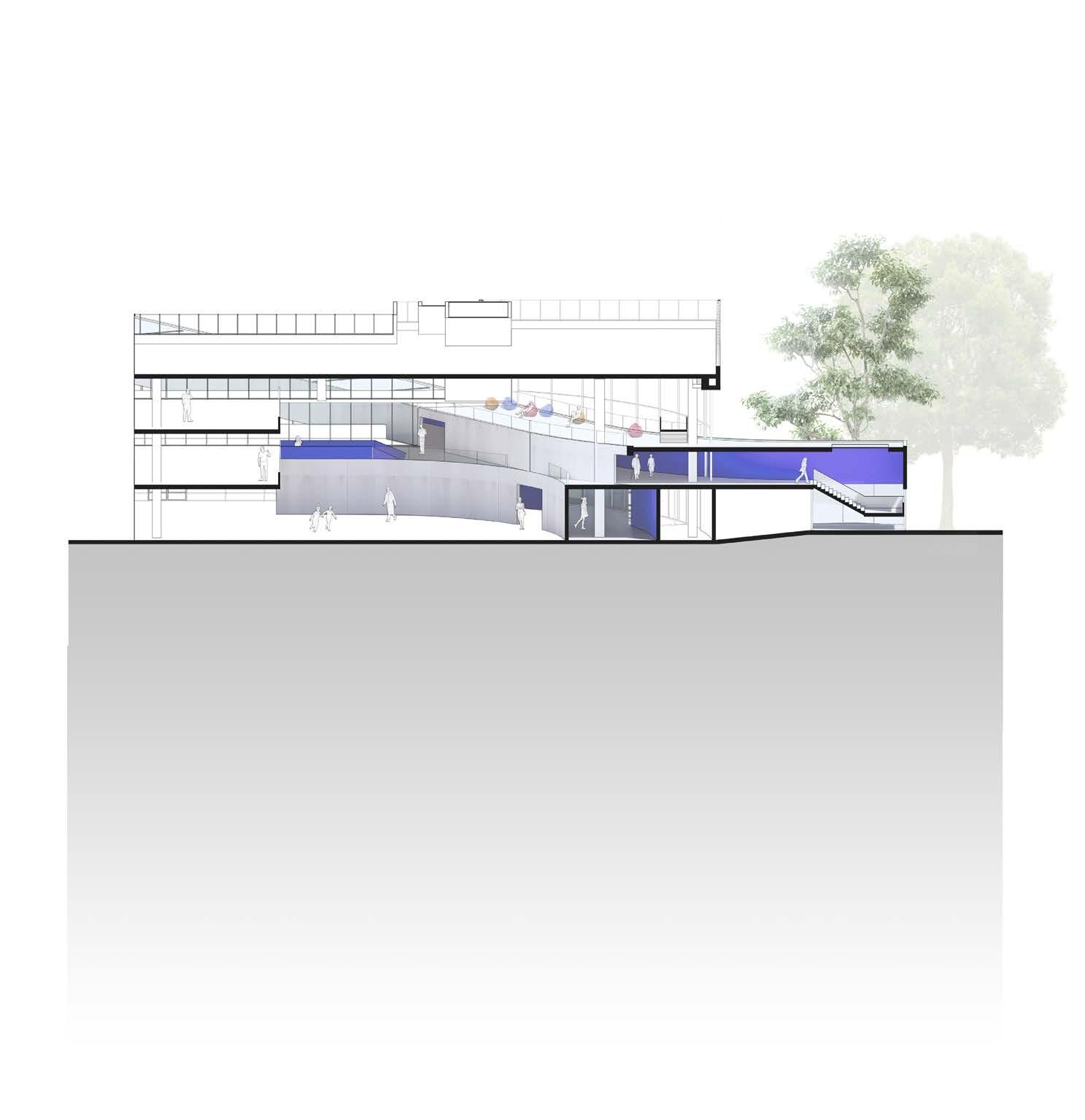
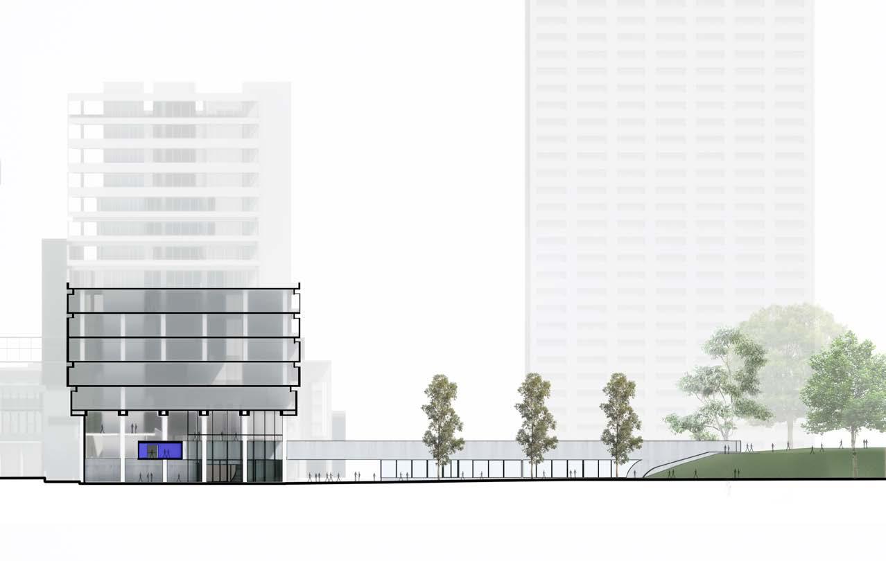
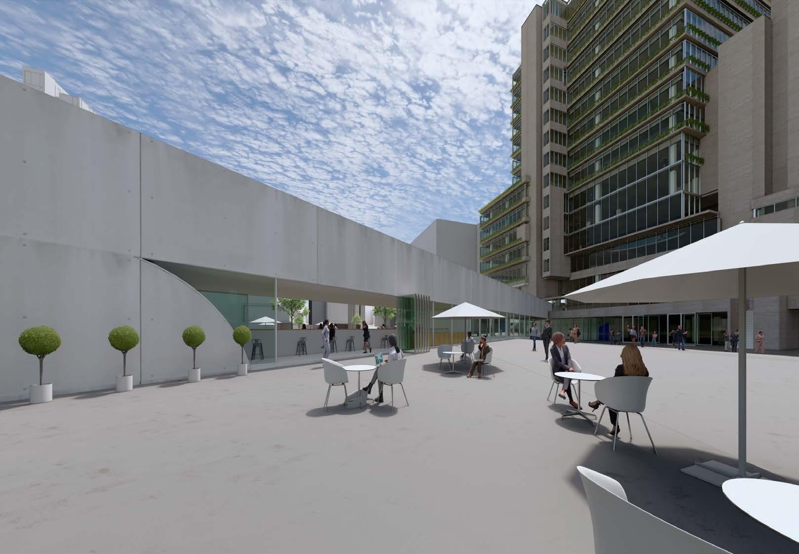
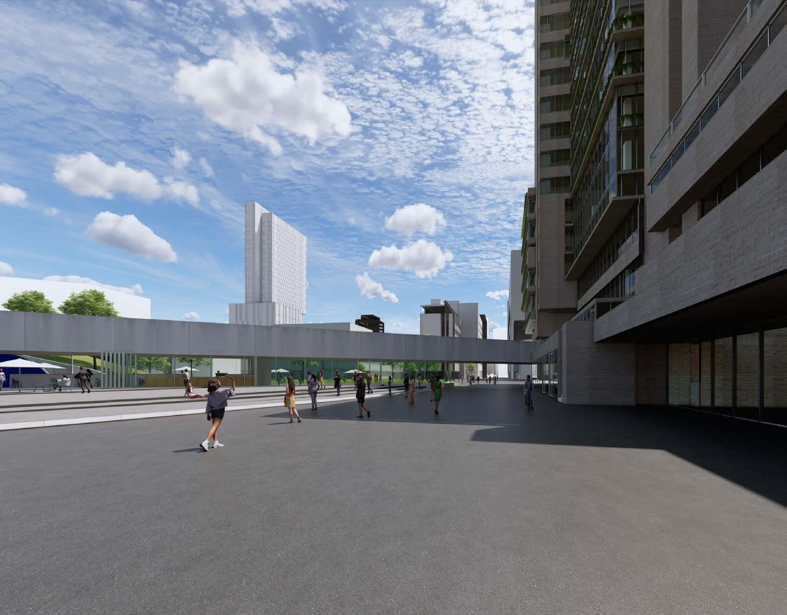
The Resilient Library is a fragment-restoration project of the Toronto Metropolitan University library (formerly Ryerson University). The proposed restoration project aims to reinvent the secluded and unengaging conformation of the existing library through means of connectivity within and around the building.
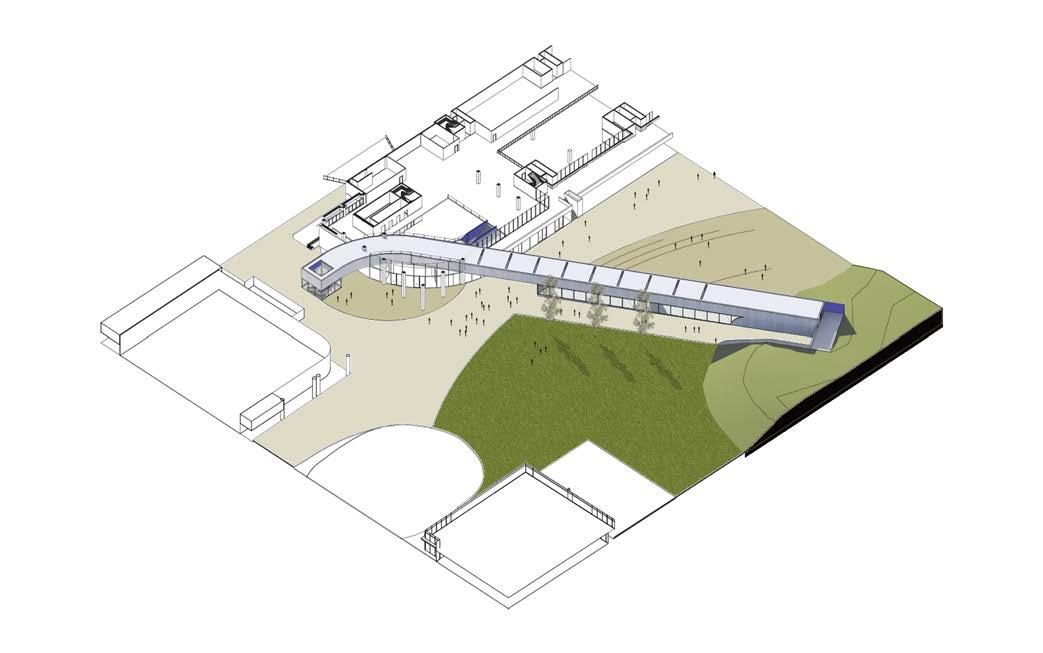
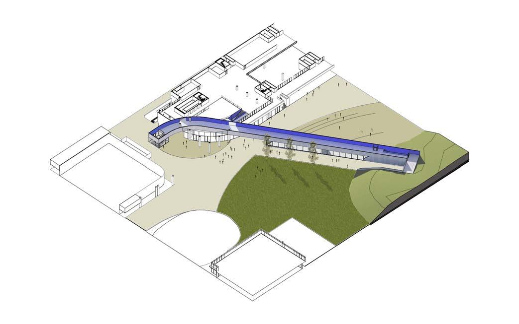
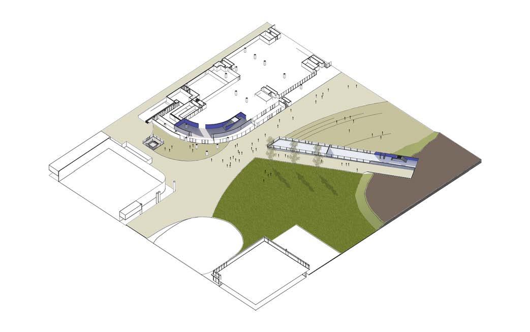
The big gesture of the proposed fragment is the introduction of two overlapping sculptural elements. One that acts as a lobby space in the atrium space, and another that punches through the library’s facade and extends to the park, which not only acts as a bridge connection, but also acts as a defined threshold between the public domain, and the campus. This allows for the library to function as a node between the library and the campus, and starts defining the blurred boundary between the campus and the city overall.
05
Revit, AutoCAD, Adobe Illustrator, Photoshop, Enscape


SITE PLAN
3 1 2 1 8 7 10 9 NELSON MANDELA WALK 5 4 6 B B 11 1. Vestibule 4. Tech-room 7. Ryerson merchandise 10 Lanscaping stair/ramp Lower Ground Level - community space and services 1:350 EXISTING
GROUND FLOOR PLAN
DEMOLISHED PROPOSED
left: exploded axonometric top right: site section bottom right: longitudinal section
AXONOMETRIC DIAGRAM
SEA FEVER SAILBOAT PROJECT
Location
Partners Professor Programs
Mediterranean Sea Beyza Gunay, Caine Wilson, Melis Aydin, Leonardo Saldanha
Semester ONGOING (unfinished project)
Massimo Paperini Rhino, AutoCAD, Adobe Illustrator, Photoshop, Vray
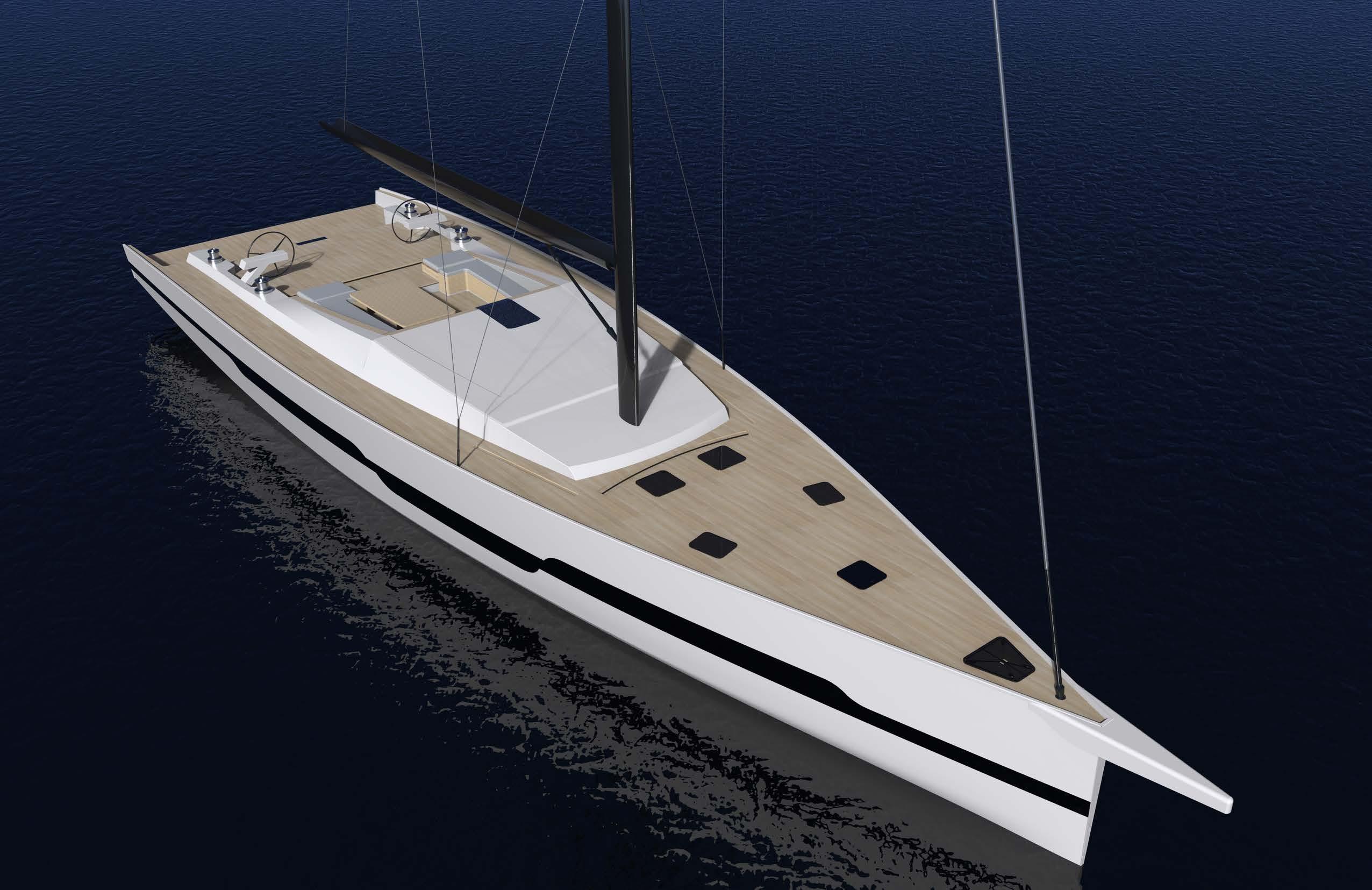
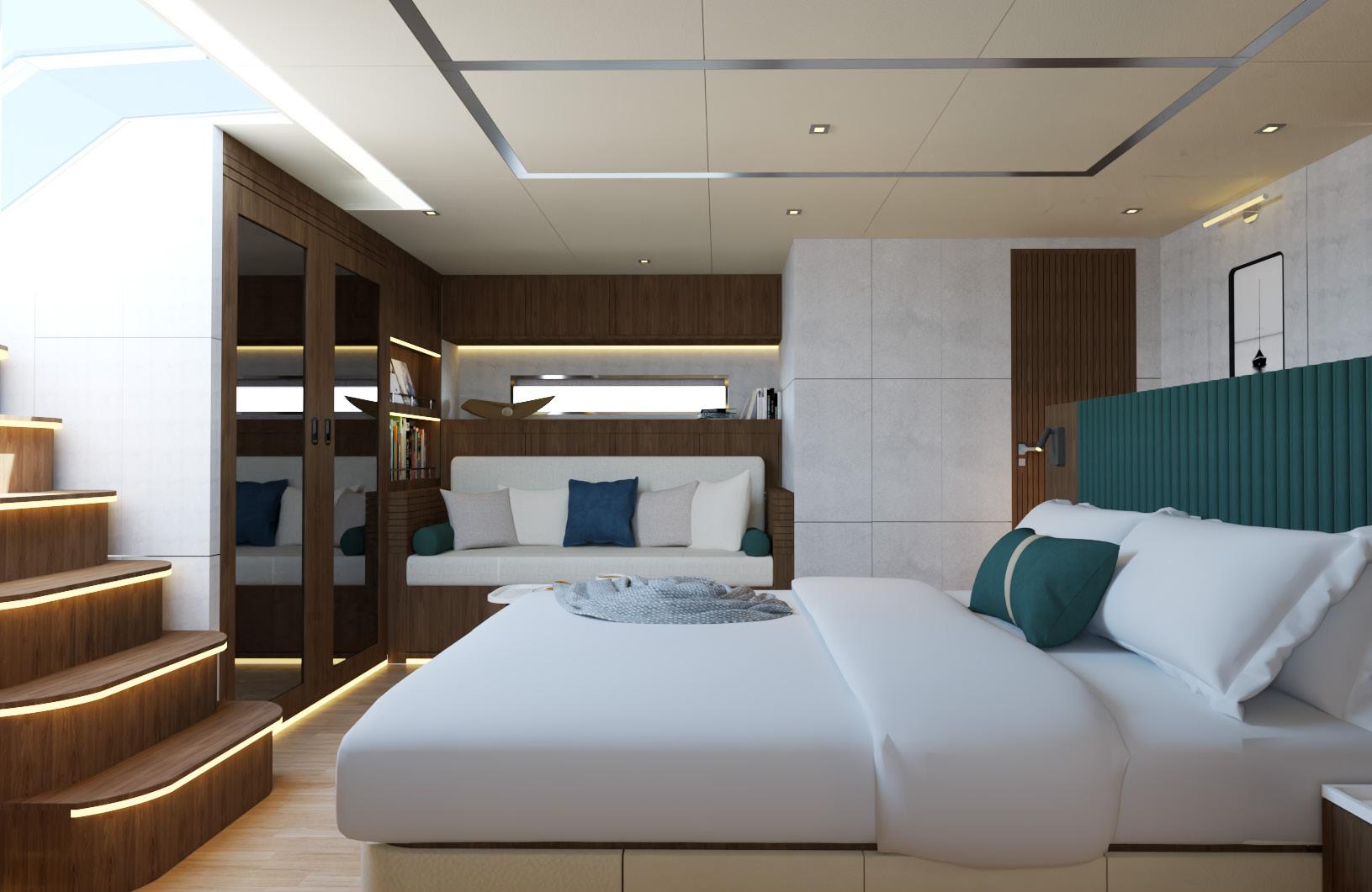
Sea Fever is a 80’ performance cruiser sailing yacht conceived to be navigating within the Mediterranean Sea. The focus of the design on this ongoing project is to achieve a dynamic design in form and interior circulation, while using low impact materials within the construction method. Its layout includes one crew cabin, two guest cabins and one master, as well as a saloon, galley and outdoor spaces such as a private beach area for the owner, a cockpit and a bow seating area. Moreover the construction is thought to be a striped planked cold molded with all renewable materials and natural fibers reinforcements.
06
GENERAL ARRANGEMENT A B C D E F A B C D E F CL FOLDING RESTING AREA 123 123 2423222120191817161514131211109876543210 25 AP MS FP COCKPIT LOWER DECK CL 700 4320 1130 1130 2000 700 2000 2051 1870 1013 700 1557 1000 1054 4530 2360 2900 3600 700 3540 654321 12 12 5015 A B C D E F A B C D E F 3600 1230 23456 2000 2270 2270 1200 980 700 70 2423222120191817161514131211109876543210 25 AP MS FP 90° 45° WL -10° 18.98m² MAIN SALOON RH 2.05m 800 1197 1553 1690 18.63m² MASTER CABIN RH 2.00m 5.99m² GUEST CABIN RH 2.00m 6.29m² GUEST CABIN RH 2.00m 2.26m² GUEST WC RH 2.00m 2.26m² GUEST WC RH 2.00m 2.02m² MASTER WC RH 2.00m 1.25m² MASTER SHOWER RH 2.00m 15.09m² TENDER GARAGE RH 1.38m 1.56m² CREW WC RH 1.95m 1.35m² LAUNDRY RH 1.95m 3.48m² CREW CABIN RH 1.95m 3.76m² CREW MESS RH 1.95m 3.85m² GALLEY RH 1.95m 1.53m² FENDER STORAGE RH 1.88m 1.08m² ANCHOR STORAGE RH 2.17m 2.30m² HALLWAY RH 2.00m 1.31m² DAYHEAD RH 2.00m
DECK DECK PLAN
LOWER
STRIP PLANKED COLD MOLDED
BULKHEAD OUTER REINFORCEMENTS
FRAME STEM
SHEAR BOARD
STRUCTURE AXONOMETRIC + HULL LINES
DWL AP MS FP st 1 st 2 st 3 st 4 st 5 st 6 st 7 st 8 st 9 st 10 st 11 st 12 st 13 st 14 st 15 st 16 st 17 st 18 st 19 st 20 st 21 st 22 st 23 wl wl wl wl wl wl wl wl wl wl 10 wl wl wl wl wl wl wl wl wl wl 10 3d2d1d6d5b4b3b2b1b DWL st 1 st 2 st 3 st 4 st 5 st 6 st 7 st 8 st 9 st 10 st 11 st 12 st 13 st 14 st 15 st 16 st 17 st 18 st 19 st 20 st 21 st 22 st 23 b 1 b 2 b 3 b 4 b 5 b 6 b 2 b 3 b 4 b 5 b 6 FP AP DWL AP MS FP st 1st 2st 3st 4st 5st 6st 7st 8st 9st 10st 11st 12st 13st 14st 15st 16st 17st 18st 19st 20st 21st 22st 23 wl 1 wl 3 wl 2 wl 4 wl 5 wl 6 wl 7 wl 8 wl 9 wl 10 wl wl wl wl wl wl wl wl wl wl 10 1 wl 1 wl 3 wl 2 wl 4 wl 5 wl 6 wl 7 wl 8 wl 9 wl 10 DWL DWL st 1st 2st 3st 4st 5st 6st 7st 8st 9st 10st 11st 12st 13st 14st 15st 16st 17st 18st 19st 20st 21st 22st 23 b 1 b 2 b 3 b 4 b 5 b 6 b 2 b 3 b 4 b 5 b 6 FP AP
SECTIONS
SECTION CREW CABIN LAUNDRY GALLEY 1 2 FENDER STORAGE ANCHOR STORAGE FOLDING RESTING AREA HALLWAY MASTER CABIN COCKPIT 2423222120191817161514131211109876543210 25 AP MS FP 2000 2000 1950 1950 1950 1880 400 2174 2055 2324 MAIN SALOON CL CL CL CL 2078 MASTER CABIN TENDER GARAGE COCKPIT WL F WL CL CL HALLWAY GUEST CABIN GUEST CABIN 2000 LONGITUDINAL SECTION CREW CABIN LAUNDRY GALLEY 1 2 FENDER STORAGE ANCHOR STORAGE FOLDING RESTING AREA HALLWAY MASTER CABIN COCKPIT 2423222120191817161514131211109876543210 25 AP MS FP 2000 2000 1950 1950 1950 1880 400 2174 2055 2324 MAIN SALOON
LONGITUDINAL
MASTER CABIN RENDER
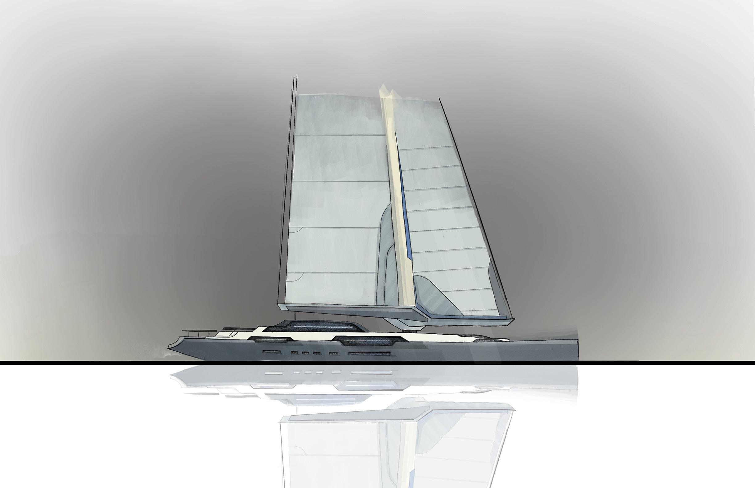
CONECEPT SKECTH | SAILING YACHT
USING EXISTING HULL LINE DRAWING TAKEN FROM GRANGER DESIGNS, I ENVISIONED A HYPOTHETICAL SAILING YACHT WITH RELATION TO PRECEDENT SAILING YACHT DESIGNS.
FLOATING CHARGING STATION
CONECEPT SKECTH |UNDERWATER MOTOR VEHICLE+ CHARGING STATION
THE CONCEPTUAL DESIGN ENVISIONS AN UNDERWATER ENERGY EFFICIENT VEHICLE AND ITS FLOATING CHARGING STATION, WHICH IS INTENDED TO PROVIDE FOR FOOD AND ACCOMMODATION
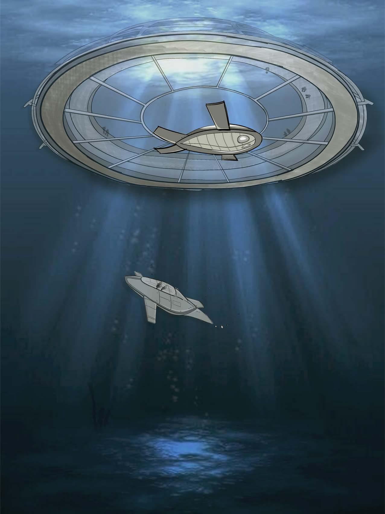
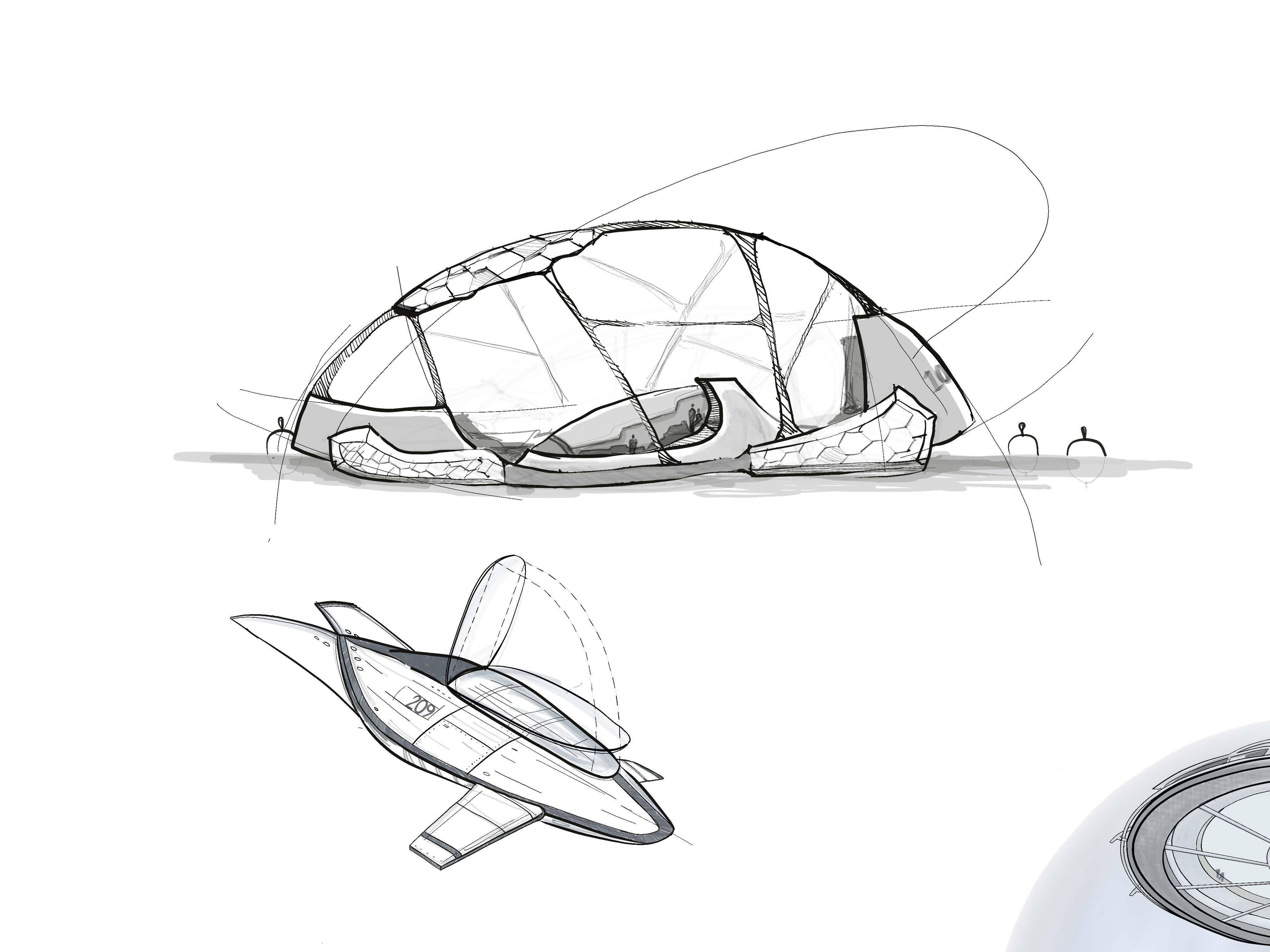
UNDERWATER MOTOR VEHICLE