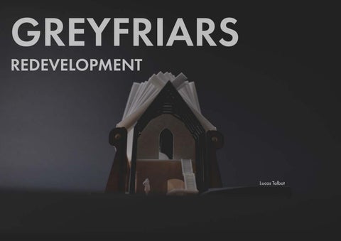
GREYFRIARS REDEVELOPMENT
Lucas Talbot
1
Contents
Historical Time line..........................................................3 Building analysis / Photographs................................4-9 Conclusions...................................................................10 Site analysis..............................................................11-15 Precedent studies.....................................................16-17 Concepts..................................................................18-19 Development...........................................................20-23 Floor plans..............................................................24- 30 Elevations.................................................................31-32 Sections...................................................................33-34 Technical Detail......................................................35-36 Exploded Isometric......................................................37 Model photos / visualisations.............................38-48 2
Historical Time-line
The Production of the gas Turbine all started with Frank Whittle, (born 1st June 1907) Frank joined the RAF and was a pilot but wanted a way of making the planes Faster.
Over The next 8 years Frank spent time raising money and developing prototypes and in 1937 he carried out his first engine test. The engine worked however revved Out of Control.
1907
1937 Frank Developed the jet engine and Showed his ideas and plans to Dr Griffiths to receive funding however his idea was dismissed.
On the 11th April 1941 whittle tested the plane on the ground and later the plane flew for 17 minutes without Failure or overheating.
1941 Eventually Frank received funding and was helped by a team of top engineers to finish developing the engine, metal manufactures of the time also developed a metal which could withstand the high temperatures, the metal was made from combination of nickel, chrome, steel and molybdenum.
Germany also Was developing a jet engine at the time and was first trialled in an aircraft, (the heinkel HE 178), on the 27th august 1939 however the engine died as the metal used for the engine couldn’t withstand the high temperatures.
The TA model was developed several times over the years to more powerful and efficient models.
1952 The development of the gas turbine started when ruston and hornsby Hired one of the lead engineers from whittles team,(bob Feilden), to develop the industrial gas turbine. The prototype 3TC was produced by 1949 and by 1952 the full production of the TA model had commenced. The TA model was sold around the world and was a great success.
2003 In 1968 the gas turbine business was acquired by GEC and became ruston gas turbines, it then changed hands several times over the next 35 years finally becoming SIEMENS in 2003 a company which is still located partly in Lincoln today and are one of the leaders in energy production sustainability.
3
Building Analysis
Historical stonework showing patina from over the years, with historical graffiti. I think this is an important aspect of the building which may be overlooked, I want this to be shown off in the
This vaulted ceiling is stunning and displays the craftsmanship that was used in the construction, The lighting is poor so it is often difficult to see the ceiling and appreciate. 4
Engraving of dates, this adds to the heritage of the building and helps keep a record of past changes and installations. 5
The brick and stonework itself plays an important part in showing the history of the building, past windows and alterations can be seen through the varying shapes of stone and materials. 6
Although the barrel vaulted timber roof structure may need some maintenance, I think it adds a feel to the building and could work well with a re purposed space. 7
The existing roof is in a state of decay and needs replacing as it has many leaks and is causing damp and other problems for the rest of the building. 8
These arched windows, are the main source of light into the ground floor and also work aesthetically in-keeping with the context of the church neighbouring the greyfriars. 9
Conclusion Building
Overall I think the building requires many changes to make it a usable space, due to the darkness of the downstairs and the lack of air circulation, damp is appearing, making it an unpleasant space. To resolve this increased levels of light would help to make this space a better environment and also would make the structure of the vaulted ceiling more visible. The later extensions which have been added onto the main greyfriars structure hold minimal historical value and would better be removed or replaced in a way that may show off the historical fabric and heritage underneath. The roof structure may need some repair however a new roof is definitely needed, potentially with roof lighting to allow for a brighter space on the first floor.
10
1:200 Winter 12AM Shadows
11
1:200 Equinox 12AM Shadows
12
1:200 Summer 12AM Shadows
For the most part of the year no/minimal sunlight is entering the upstairs windows meaning that it becomes dark and not an enjoyable space. 13
Wind Map 1:500
The wind funnelling around the church may cause further damage to the existing roof. The area to the east side of the building is most sheltered and 14 would act as a good place for an entrance.
Spot Heights and Pedestrian Movement 1:200
10m 21m
9m 20m 9m
13m 8.5m
8.5m
63m
26m
The elevation of the church and other surrounding buildings is significant to that of the greyfriars meaning that the building could be extended upwards without being obtrusive towards the context and 15 surrounding buildings.
Milwaukee Art Museum
Location : 700 N. Art Museum Drive Milwaukee, Wisconsin, US Architect : Santiago Calatrava Project Year : 2001 Total Area : 13,196 square meters
The pavilion features a spectacular kinetic structure, a brise-soleil with louvres that open and close like the wings of a great bird. When open the shape becomes a sign, set against the backdrop of the lake, to herald the inauguration of new exhibitions. The pivot line for the slats is based on the axis of a linear mast, inclined at 47 degrees, parallel to the adjacent bridge mast. The design of Milwaukee art museum allows for a future expansion, offset from but symmetrical to the exhibition facilities, on the other side of the Kahler building. 16
AutobarnAuto Barn-Bindloss Bindloss Dawes Dawes
Upon observation a large central skylight can be seen at the apex of the pitched roof, this provides a large amount of natural light which illuminates the spaces below extremely well, leading to a bright and well lit space, the trees surrounding the building can also be seen framing the skylight and connecting the building to the surrounding context. This can be incorporated into my design by showing the church spire and turbine blades canopy through the roof of the greyfriars.
https://www.archdaily.com/998609/autobarn-bindloss-dawes?ad_source=search&ad_medium=projects_tab
17
Interior Concept
18
Exterior Concept
The original idea was to have a glass roof to let more light in, however during the summer months, especially with increasing global temperatures, overheating may occur. To solve this I thought about having a cantilevered canopy made from large turbine blades to shade the building and contrast with the old stonework celebrating both the old craftsmanship and new technology and engineering. Upon review the cantilever would be difficult to make structurally and would block needed sunlight in the winter. To solve this a concept of a moveable canopy which took inspiration from the original pitch of the roof came about.
19
Exterior Development
Here are some developed drawings of the turbine blades on the roof in different positions. To the left a proposed extension made from exposed steel frame and frosted glass to help reflect sunlight which would have open views of the stone facade celebrating the historic stonework.
20
Interior Development
On the top floor a cafe will be situated with information posters and displays and a centrepiece exploded gas turbine, suspended over a void in the floor so that it can be viewed by people both up and downstairs The idea of the ground floor is to make people experience what a gas turbine does. The idea is to make people feel as though they are the molecules of air flowing through a turbine through hot/cold air and compression and expansion of spaces, a light display with lights changing from red to blue in the centre as another added interactive display. 21
Ground Floor Development
Development of the Ground floor showing areas of hot and cold and also the areas of contraction and release. As well as showing the skylight and the open space underneath which can be used to pause and view the exploded gas turbine and roof structure from below. 22
Spacial Development
Through exploration of the existing structure, spaces can be determined and decided while maintaining views and displaying of the heritage and historical fabric.
23
Site Plan 1:500
24
Ground Plan 1:200
Disabled friendly toilets.
Arches varying in size to create feelings of compression and release, whilst changing in colour to match the change in temperature through heat lamps and cold air blowers.
Outdoor storage
A light display accessible through curtains to keep it dark inside, with a skylight at one end looking up to the above gas turbine.
Stairs descending down to ground floor area from extension.
Main entrance. A large turbine blade embedded into the floor under glass, illuminated with leds.
25
Ground Plan 1:200
26
First Floor Plan 1:200
Dotted line showing the elevated exploded gas turbine. Storage cupboard for cafe.
Display boards surrounding the upstairs walls
Cafe area with tables and chairs
27
First Floor Plan 1:200
28
Ceiling Plan 1:200
Original beams kept with glass panel on top to allow light through and views of the above turbine blades.
29
Fire Egress 1:200
Emergency staircase
First Floor Plan 1:200
Emergency staircase
Ground Floor Plan 1:200
30
North Elevation 1:200
Extension housing the emergency staircase and storage areas using removed stone from other areas of the building and locally sourced limestone, shallow angled pitched roof and slotted windows similar in shape to that of the very first greyfriars before the use of large glass panes.
31
32
East Elevation 1:200
Section Scale 1:200
Section Showing the downstairs and upstairs displays as well as access to the upper floor.
33
Section Scale 1:200
34
Technical Detail 1:10
Detail showing the mechanism used to turn the turbine blades, two motors per side of the building will turn the large bar to move the blade in and out to let more or less sunlight in, see model photos for demonstration.
35
Technical Details
Motor Mechanism 1:50
Turbine blade profiles1:20
36
Exploded Isometric
Model Photos
38
39
40
41
42
43
44
45