10 minute read
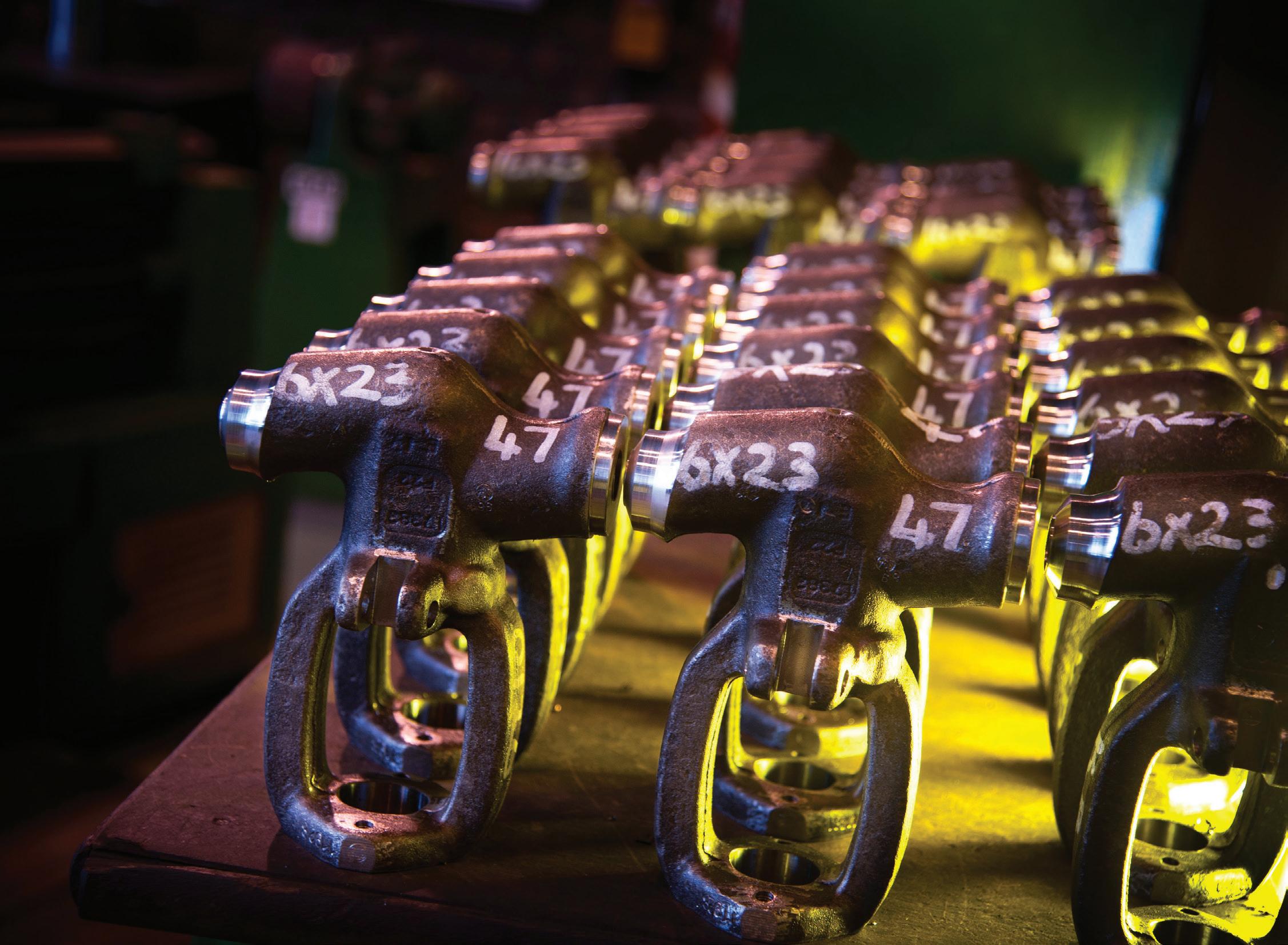
BEARINGS

10 Hydraulics tips you need to know
Seals, gaskets and o-rings are all key components to the success of hydraulic applications. Without these components, high pressure systems would be impossible.
Advertisement
Selecting the right material, durometer and temperature and a complete understanding of a hydraulic system allow engineers to ensure quality performance in every fluid power application.
Outside factors are a vital component of hydraulic systems.
Demands placed on hydraulic systems constantly change as automotive, aerospace and oil and gas industries require greater efficiencies. Just as selecting the best hydraulic fluid requires a basic understanding of fluid characteristics, choosing the best sealing material requires an in-depth understanding of factors that may influence performance.
Temperature Range:
All possible environments must be taken into consideration before selecting a material. Where will the application be used, and what types of climate will the application be exposed to? Will Ozone be a factor? FKM compounds, for example, may only function to -25°C – not necessarily suitable for all possible temperature requirements. Applications that may be exposed to extreme environments require full communication between customers and manufacturers.
Fluid Compatibility:
Depending on the chemistry of the given oil and temperature, the amount of swell can vary. Today, elastomers exist that swell very little when exposed to water or oil.
Too much swell can cause deterioration, cracking or even premature failure – which is why it is critical to keep this in mind. Choose the right polymer to ensure full and proper function. Fluids and seals should be checked to make sure they are compatible, and will not interfere with proper operation. Even new fluid additives can attack rubber seals. New amine preservatives in hydraulic oils can attack standard FKM seals, causing premature failure. The amine additives attack the backbone of the polymer, resulting in embrittlement of the rubber.
O-Ring friction is more common than you think.
The need to reduce o-ring friction and wear is a major factor in product design for hydraulic valves and cylinders, pneumatic tools and plumbing devices. There are two ways to help reduce o-ring friction.
Evaluate the o-ring and gland conditions.
Many times, a gland width may not be large enough to allow space to accommodate the o-ring volume. This is a crucial factor in proper o-ring function. Reducing seal squeeze will decrease the overall seal friction. Just be sure these adjustments do not compromise the performance of the o-ring. A gland calculator can also be a useful tool in giving accurate guidelines for application values like compression, stretch and volume fill.
Introduce lubricity to the seal material.
Lubricants that are compatible with system components are extremely helpful in reducing friction. They are great for dynamic applications where the rubber seal is moving during use.Internally lubricated compounds have proven especially effective in applications requiring low friction performance without the reduction of squeeze. PTFE powder can be milled into commonly used rubber compounds to reduce friction and improve abrasion resistance. Erucamide and Oleamide can be added to

rubber to bloom to the surface after molding to reduce initial stiction in dry applications.
A standard o-ring can in fact be used for non-circular grooves.
An o-ring provides a simple and economical solution for an axial face seal gasket. For non-circular grooves, circular o-rings can be formed to fit. In order to use a standard circular o-ring, the inside corner radius of the groove should not be less than three times the o-ring crosssection diameter. Just be sure to use the recommended gland design for static axial seals. The length of the o-ring centerline should be equal to the length of the groove centerline. Below is an equation to assist in determining the o-ring inside diameter: O-Ring Inside Diameter = (Groove CL length / 3.14) – O-Ring CS If a standard circular o-ring cannot be applied to your face seal application, contact appropriate professionals for assistance with designing a custom-molded gasket solution.
O-Ring cross sections may not always be circular.
When initially removed from the hardware, the o-ring may be oval-shaped. It is the deformation of the o-ring that provides a seal. When squeezed, the cross-section of the o-ring resists with a normal force – this force creates the initial barrier for sealing. As the o-ring continues to function in the hydraulic application (and experiences thermal cycles, exposures to chemicals and pressure cycles) the stress in the rubber material will begin to relax. This relaxation or permanent deformation is compression set. Compression set should be expected with most applications and seal materials. In the case of excessive compression set, the seal has lost its resilience – the normal force required for maintaining a sealing barrier. Application failure will usually be detected at low pressures. The seal and gland design standards take into account responsible compression set values for the various seal materials.
Hydraulic applications may require frequent design improvements (and that’s OK).
Let’s say, for example, an o-ring part needs to pass a port in a piston application. This may cause damage to the seal, but several improvements can be made to alter the design: • Reduce the inside diameter of the o-ring, so the nominal stretch is in the 10 percent range. This will help keep the o-ring tight against the piston or spool component. • Break the edges of the port where it meets the bore. This is difficult on small-bore components, so a trick might help: Drop a piece of piano wire into the port and spin – the edges at the bore surface will break. • Design the o-ring cross-section to be as large as possible. Design the port diameter to be as small as the application will allow. Multiple small ports may provide the necessary flow. • Increase the full bore diameter at the location of the port. This will relieve squeeze on the perimeter of the o-ring. Just be sure that there is a gradual transition between the bore diameters so the seal can be loaded again gently.
Chamfering is key in hydraulic and pneumatic applications.
If the part lacks a quality lead-in chamfer, a portion of the seal may be pinched on the outer diameter for a piston (or inner diameter for a rod-type application). The ideal leadin chamfer is 15° to 20°. For a piston configuration, the major bore diameter should be near the assembled outer diameter of the seal, and a rod configuration should have the minor chamfer diameter near the assembled inner diameter of the seal.
Piston seals are always constructed with an interference fit. In order to avoid damage during part installation, lead-in chamfers and rounded edges must be made on the cylinder
barrel. This process of chamfering allows for minimal damage and easy function in hydraulic applications.
When sealing end caps, radial seals are superior to axial seals.
Many designers want to incorporate an axial face seal between the cylinder and cap component. However, the performance of the face seal is highly dependent on the clamp force of fasteners or threads in the cap itself. There is little room for hard stops to control squeeze on the gasket, which means the cap is tightened to a “feel.” A radial o-ring seal configuration is better suited for cap and plug applications. Whether a male or female gland, the hardware dimensions control the amount of squeeze on the seal – not the torque of the fastening mechanism. As long as the seal assembly is engaged over the cylinder outer diameter, the performance of the o-ring seal is not dependent on the fastener or thread torque. This type of configuration will provide quality seal performance over wide pressure ranges and conditions.
It’s normal for rubber to initially stick to an application.
Some units that have been idle for extended periods of time are difficult to cycle initially. The rubber material may adhere to the mating hardware surface, creating a high breakaway force. It is important to recognize that rubber acts like a highly viscous fluid. Over time, the seal material will tend to flow into the micro-features of the hardware surface finish. This process will resemble mechanical adhesion. A highly polished hardware surface will also create a type of suction between the two mating surfaces. In all dynamic sealing applications, the addition of a lubricant will greatly reduce friction and extend the seal life. The recommended hardware surface finish for dynamic seal applications is a maximum of 16 Ra, with the ideal being between 8-12 Ra (micro-inches). Applying a matte finish to the o-ring has helped in light duty applications.
The right hydraulic seals begin with the proper material.
O-Rings are affordable, simply produced and have versatile applications in automobiles, engines, medical uses and aerospace. They function well under diverse environments due to the diverse scope of material used in fabrication. Understanding the range of materials available – and their tendencies – will help in determining which is most appropriate for an application. Nitrile (Buna-N): Widely used offering excellent resistance to oils, hydraulic fluids and fuels. Ideal for applications in hydraulic and pneumatic systems. Temperature Range: -40°C to +135°C. HNBR is in the same family as NBR but offers better ozone, higher temperature and weather resistance Ethylene Propylene: Has gained wide seal industry acceptance for its excellent ozone and chemical resistant characteristics. It is ideal for outdoor weather-resistant uses. Works well with water, steam, brake fluids and alcohols. Fluorocarbon (Viton™): Offers excellent resistance to petroleum products, solvents, broad range of chemicals and high temperatures. Excellent for a variety of applications, both static and dynamic, such as seals for automotive, chemical processing and aircraft fuel systems, vacuum service and other high temp uses. Neoprene: Functions well in refrigeration units of air conditioning systems. Neoprene compounds offer resistance to wide range of Freon as well as giving some resistance to the oils used from lubricating these systems. Polyurethane: Offers outstanding abrasion resistance and tensile strength. Ideal for seals used under hydraulic pressure and applications where highly stressed parts are subject to wear. Polyurethane is often used in hydraulic cylinders and valves, pneumatic tools and firearms. Urethanes do have a limited temperature range and are more susceptible to compression set at higher temperature.
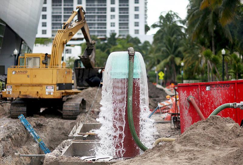
The majority of hydraulic system failures are a result of contamination.
High dirt environments require extra consideration when it comes to contamination control. This could lead to internal leakage, lowering the efficiency of hydraulic pumps, motors and cylinders. Valves could lose the ability to control flow and pressure within the system.
Without minimizing contamination, the following malfunctions may occur:
• Degradation (changes over time in pump flow rates, valve leakage and wear of cylinder barrels causing speed decline) • Transient or intermittent failures • Catastrophic – complete failure of a system Contamination in hydraulic systems can be broken down into three different categories – gaseous, liquid and solid. Air can lead to a reduction in lubricating properties, liquid can cause rust and solid particles can cause significant surface degradation. However, there are a number of ISO standards for measuring and reporting the levels of contamination in fluids. Making sure you have new oil filtration systems in place, and management to monitor contamination, will help in keeping systems clean. Remember to do the following: • Proper fluid selection for a system – know your environment • Proper fluid handling, including storage • Regular system maintenance
https://www.applerubber.com/fluid/ HydraulicsWhitepaper.pdf

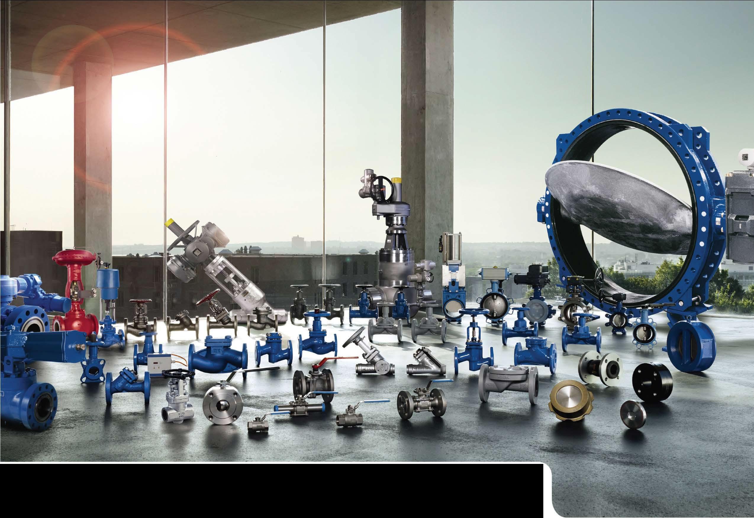
We offer valves for precision processes - and demandingapplications
Our valves fulfill the highest of standards and are designed for many years of safe and reliable operation. Our service specialists regularly check, monitor and maintain all relevant system components - depending on what has been agreed. Our modular framework agreements offer you individual service and spare parts concepts. And we even go one step further. We additionally check systems for efficiency in order to reduce operating costs and increase productivity. For example, with the SES System Efficiency Service.
ZTS GATE VALVE
GATE VALVE AKG-A/AKGS-A
STAALWEDGE GATE VALVEAKDS/AKD NORI 500
Contact our dedicated Valves Sales Engineers for all your Valve requirements Tel: 011-876-5600 • Email: info-za@ksb.com KSB Pumps and Valves (Pty) Ltd www.ksb.com/ksb-za Your B-BBEE Partner
BOA -H