
11 minute read
Repeat Steps 1 through 3 for the remaining connecting rod bearings


Previous Screen
Product: MOTOR GRADER Model: 160H ES MOTOR GRADER 2HS Configuration: 160H Motor Grader 2HS00001-UP (MACHINE) POWERED BY 3306 Engine
Advertisement
Disassembly and Assembly 3304B and 3306B Engines for Caterpillar Built Machines Media Number -SENR5598-09 Publication Date -01/01/2013 Date Updated -25/01/2013
Connecting Rod Bearings - Remove i00987487
SMCS - 1219-011
Removal Procedure
Start By:
A. Remove the engine oil pump. Refer to Disassembly and Assembly, "Engine Oil Pump - Remove". B. Remove the oil pan plate. Refer to Disassembly and Assembly, "Engine Oil Pan Plate - Remove and Install".
NOTICE
Keep all parts clean from contaminants.
Contaminants may cause rapid wear and shortened component life.
1. Turn the crankshaft until two of the pistons are at the bottom center. Remove connecting rod nuts (1) from the connecting rod. Remove connecting rod cap (2) for each connecting rod.
Note: The connecting rod bolts can fall out of the connecting rods when the connecting rod nuts are removed.
2. Remove the lower half of the connecting rod bearing from connecting rod cap (2) .
3. Carefully push the connecting rod into the cylinder liner for bearing removal. Remove the upper half of the connecting rod bearing from the connecting rod.
4. Repeat Steps 1 through 3 for the remaining connecting rod bearings.
Copyright 1993 - 2019 Caterpillar Inc. All Rights Reserved.
Private Network For SIS Licensees. Tue Dec 3 01:04:53 UTC+0800 2019
Previous Screen
Product: MOTOR GRADER Model: 160H ES MOTOR GRADER 2HS Configuration: 160H Motor Grader 2HS00001-UP (MACHINE) POWERED BY 3306 Engine
Disassembly and Assembly 3304B and 3306B Engines for Caterpillar Built Machines Media Number -SENR5598-09 Publication Date -01/01/2013 Date Updated -25/01/2013
Connecting Rod Bearings - Install
SMCS - 1219-012
Installation Procedure
Table 1 Tool Part Number Part Description Qty
A - Plastigage - i00987670
NOTICE
Keep all parts clean from contaminants.
Contaminants may cause rapid wear and shortened component life.
Note: Install the connecting rod bearings dry when the clearance checks are made. Put clean engine oil on the connecting rod bearings for final assembly.
1. Install the upper half of the connecting rod bearing in the connecting rod.
2. Install the lower half of the connecting rod bearing in the connecting rod.
Note: Align the tabs on the back of the connecting rod bearings with the tab grooves in the connecting rod.

Illustration 1 g00487493
3. In order to check the connecting rod bearing clearance, put Tool (A) on the connecting rod bearing, as shown.
4. Put clean engine oil (SAE 30) on the connecting rod bolts.
NOTICE
When the connecting rod caps are installed, ensure that the identification marks are aligned.
Illustration 2 g00487412
Note: Do not turn the crankshaft when Tool (A) is positioned.
5. Ensure that connecting rod (3) is in position on the crankshaft. Install connecting rod cap (2) and connecting rod nuts (1) on connecting rod (3) .

Illustration 3 g00287852
6. Tighten the connecting rod nuts to a torque of 40 ± 4 N·m (30 ± 3 lb ft). Mark the position of the nuts. Tighten each nut for an additional 90 degrees (1/4 turn).
7. Remove the connecting rod cap. Measure Tool (A) on the bearing surface before Tool (A) is removed. The clearance between the connecting rod bearing and a new crankshaft should be 0.076 to 0.168 mm (.0025 to .0066 inch). The clearance between the connecting rod bearing and a used crankshaft should be 0.25 mm (0.01 inch).
8. Install connecting rod cap (2) and connecting rod nuts (1) on connecting rod (3). Repeat Step 6 in order to tighten the nuts.
9. Repeat Steps 1 through 8 for the remaining connecting rod bearings.
End By:
a. Install the oil pan plate. Refer to Disassembly and Assembly, "Engine Oil Pan Plate - Remove and Install". b. Install the engine oil pump. Refer to Disassembly and Assembly, "Engine Oil Pump - Install".
Copyright 1993 - 2019 Caterpillar Inc. All Rights Reserved. Private Network For SIS Licensees. Tue Dec 3 01:05:48 UTC+0800 2019
Previous Screen
Product: MOTOR GRADER Model: 160H ES MOTOR GRADER 2HS Configuration: 160H Motor Grader 2HS00001-UP (MACHINE) POWERED BY 3306 Engine
Disassembly and Assembly 3304B and 3306B Engines for Caterpillar Built Machines Media Number -SENR5598-09 Publication Date -01/01/2013 Date Updated -25/01/2013
Crankshaft Main Bearings - Remove
SMCS - 1203-011
Removal Procedure
Table 1 Required Tools
Tool Part Number Part Description Qty
A 2P-5518 Bearing Tool 1 i00990466
Start By:
A. Remove the engine oil pump. Refer to Disassembly and Assembly, "Engine Oil Pump - Remove". B. Remove the oil pan plate. Refer to Disassembly and Assembly, "Engine Oil Pan Plate - Remove and Install".
NOTICE
Keep all parts clean from contaminants.
Contaminants may cause rapid wear and shortened component life.

Illustration 1 g00479056
1. Remove No. 1, 3, 5 and 7 main bearing caps (3). Remove the lower halves of the main bearings from the main bearing caps.
Note: If the crankshaft is turned in the wrong direction, the tab on the bearing will be pushed between the crankshaft and the bearing area in the cylinder block. This can result in damage to the cylinder block and/or the crankshaft.
2. Install Tool (A) in the oil hole in the crankshaft journal. Turn the crankshaft in order to remove the upper halves of main bearings (1) .
3. Remove crankshaft thrust plates (2) from the crankshaft.
4. Install No. 1, 3, 5, and 7 main bearing caps (3). Refer to Disassembly and Assembly, "Crankshaft Main Bearings - Install".
5. Remove the remaining main bearing caps (No. 2, 4 and 6) (3). Remove the lower halves of the main bearings from the main bearing caps.
Note: If the crankshaft is turned in the wrong direction, the tab on the bearing will be pushed between the crankshaft and the bearing area in the cylinder block. This can result in damage to the cylinder block and/or the crankshaft.
6. Install Tool (A) in the hole in the crankshaft journal. Turn the crankshaft in order to remove the upper halves of main bearings (1) .
Copyright 1993 - 2019 Caterpillar Inc. All Rights Reserved. Private Network For SIS Licensees. Tue Dec 3 01:06:44 UTC+0800 2019
Previous Screen
Product: MOTOR GRADER Model: 160H ES MOTOR GRADER 2HS Configuration: 160H Motor Grader 2HS00001-UP (MACHINE) POWERED BY 3306 Engine
Disassembly and Assembly 3304B and 3306B Engines for Caterpillar Built Machines Media Number -SENR5598-09 Publication Date -01/01/2013 Date Updated -25/01/2013
Crankshaft Main Bearings - Install
SMCS - 1203-012
Installation Procedure
Table 1 Required Tools
Tool Part Number Part Description Qty
A 2P-5518 Bearing Tool 1
B - Plastigage -
C 8T-5096 Dial Indicator Group 1 i03706647
NOTICE
Keep all parts clean from contaminants.
Contaminants may cause rapid wear and shortened component life.
Note: Install the main bearings dry when the clearance checks are made. Put clean engine oil on the main bearings for final assembly.
Note: Ensure that the upper halves and the lower halves of the main bearings are installed so that the bearing tabs fit into the notch in the cylinder block and in the main bearing caps.

Illustration 1 g00479169

Illustration 2 g00479171
1. Use Tooling (A) and install the new upper halves of main bearings (1) in the cylinder block. Install new lower halves of main bearings (1) in main bearing caps (2) .
Note: When the bearing clearance is checked and the engine is in an upright position or on the engine's side, the crankshaft must be supported against the upper halves of the main bearings. This is done in order to get a correct measurement with Tooling (B) . If the crankshaft is not supported, the weight of the crankshaft will cause an incorrect reading. If the engine is not in an upright position or on the engine's side, it is not necessary to support the crankshaft. Do not rotate the crankshaft when Tooling (B) is positioned.
Note: Refer to Guideline For Reusable Parts, SEBV0544, "Engine Bearings and Crankshafts" for complete details concerning the measurement of bearing clearances.
2. Check the main bearing clearance with Tooling (B) , as follows:
a. Put a piece of Tooling (B) on the crankshaft journals, as shown.
Note: Make sure that the part number on the main bearing cap is facing toward the front of the engine. Also, make sure that the number on the main bearing cap matches the number on the cylinder block on the left side of each main bearing cap.
c. Put a mark on each bolt and main bearing cap. Tighten the bolts for an additional 90 degrees (1/4 turn).
d. Remove the main bearing caps and measure Tooling (B) in order to find the bearing clearance. The main bearing clearance for new bearings must be 0.076 to 0.165 mm (0.0030 to 0.0065 inch). The maximum permissible clearance with used bearings is 0.25 mm (0.010 inch).

Illustration 3 g00479203
3. Put clean oil on thrust plate (4) and install a new thrust plate for the rear main bearing. Install the new thrust plate so that the mark that is identified as the "BLOCK SIDE" faces toward the cylinder block and toward the tabs on the thrust plates in the machined area on the cylinder block. Tabs (3) on thrust plate (4) will not allow the thrust plate to be installed backward.

Illustration 4 g00479205
5. Remove the remainder of the main bearing caps. Perform Steps 1, 2 and 4 again.

Illustration 5 g00479212
6. Use Tooling (C) in order to check the crankshaft end play. The end play is controlled by the thrust plates on the rear main bearing. End play with new bearings must be 0.122 to 0.579 mm (0.0048 to 0.0228 inch).
End By:
a. Install the oil pan plate. Refer to Disassembly and Assembly, "Engine Oil Pan Plate - remove and install". b. Install the engine oil pump. Refer to Disassembly and Assembly, "Engine Oil Pump - Install".
Copyright 1993 - 2019 Caterpillar Inc. All Rights Reserved. Private Network For SIS Licensees. Tue Dec 3 01:07:40 UTC+0800 2019
Thank you very much for your reading. Please Click Here. Then Get COMPLETE MANUAL. NO WAITING

NOTE: If there is no response to click on the link above, please download the PDF document first and then click on it.
Previous Screen
Product: MOTOR GRADER Model: 160H ES MOTOR GRADER 2HS Configuration: 160H Motor Grader 2HS00001-UP (MACHINE) POWERED BY 3306 Engine
Disassembly and Assembly 3304B and 3306B Engines for Caterpillar Built Machines Media Number -SENR5598-09 Publication Date -01/01/2013 Date Updated -25/01/2013
Crankshaft - Remove
SMCS - 1202-011
Removal Procedure
Table 1 Required Tools
Tool Part Number Part Description Qty
A
B 138-7575 Link Bracket 2
8B-7551 Bearing Puller 1
8B-7549 Puller Leg 2
3H-0465 Push-Puller Plate 4
1B-4207 Full Nut 2
8B-7560 Step Plate 1
1P-0820 Hydraulic Puller 1
9U-6600 Hand Hydraulic Pump 1 i01112752
Start By:
A. Remove the front housing. Refer to Disassembly and Assembly, "Front Housing - Remove". B. Remove the flywheel housing. Refer to Disassembly and Assembly, "Flywheel Housing - Remove and Install". C. Remove the engine oil pump. Refer to Disassembly and Assembly, "Engine Oil Pump - Remove". D. Remove the oil pan plate. Refer to Disassembly and Assembly, "Engine Oil Pan Plate - Remove and Install".
Keep all parts clean from contaminants.
Contaminants may cause rapid wear and shortened component life.
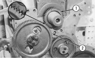
Illustration 1 g00503163
1. Turn the crankshaft until timing mark "C" on crankshaft gear (1) is aligned with timing mark "C" on camshaft gear (2) .

Illustration 2 g00503180
2. Remove connecting rod nuts (4) and connecting rod caps (3) from the connecting rods.
NOTICE
Note: The piston will be difficult to push down into the cylinder when the inlet valves and exhaust valves are closed.
3. Push down on the pistons that are not at the top center position in order to clear the crankshaft.
4. Remove main bearing cap bolts (5) and main bearing caps (6) from the cylinder block.
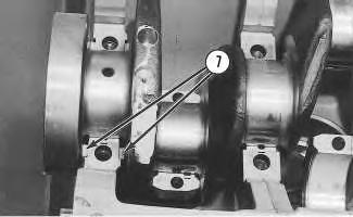
Illustration 3 g00503320
5. Remove thrust plates (7) from the rear main bearing.

Illustration 4 g00503353
6. Install Tool (A) and a suitable lifting device on crankshaft (8), as shown. Lift the crankshaft straight up from the cylinder block. The weight of the 3304B crankshaft is 65 kg (143 lb). The weight of the 3306B crankshaft is 95 Kg (210 lb).

Illustration 5 g00503384
7. Use Tool (B) in order to remove the crankshaft gear and the oil seal wear sleeve from the crankshaft.
Note: Put identification marks on the bearings and on the bearing caps prior to removal.
8. Remove the main bearings from the main bearing caps and from the cylinder block. Remove the connecting rod bearings from the connecting rods and from the connecting rod caps.
Copyright 1993 - 2019 Caterpillar Inc. All Rights Reserved.
Private Network For SIS Licensees. Tue Dec 3 01:08:36 UTC+0800 2019

