18 minute read
Cover Story


A Practical Method of Rotary Spreader Calibration
Max Schlossberg, Ph.D.
Advertisement
This article was originally published in Pennsylvania Turfgrass, Fall 2022 and is reprinted with permission.
Accurate and uniform distribution is the essence of effective turfgrass fertilization, and broadcast application of granular fertilizer via spreader is the most common method used. Spreader calibration entails the measuring and establishment of fertilizer output from a spreader operating over a known area.
The first step in calibrating any spreader
Regardless of which book, article, website, or fact sheet you are reading, the first step of spreader calibration is determining the granular fertilizer or amendment application rate in lbs product per 1000 sq. ft. (M). For pesticides, lime, or amendments, this is typically best achieved by following label or soil test recommendations. For nutrient recommendations provided in a specific soil test report; e.g., a recommendation of 2 lbs K2O per M, the fertilizer grade will be required to scale the fertilizer application rate. This is achieved by inserting the recommended nutrient delivery rate into the numerator and inserting the decimal form of the percent nutrient contained in the fertilizer into the denominator (Figure 1).
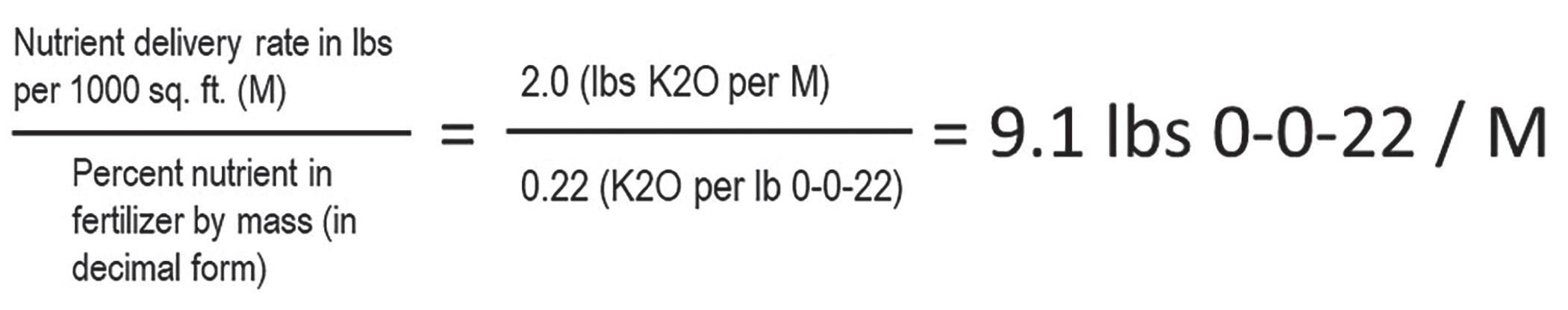
Figure 1
It is crucial that the percent nutrient contained within the fertilizer, reported as a percentage by mass either in the fertilizer grade or guaranteed analysis, be included in its decimal form. In this example, the desired K-Mag fertilizer (0-0-22) application rate is 2 divided by 0.22, or 9.1 lbs K-Mag fertilizer (0-0-22) per M. Insert this value into the ‘Desired fert/amend application rate (lbs/M)’ slot of the rotary spreader calibration equation (Figure 2).
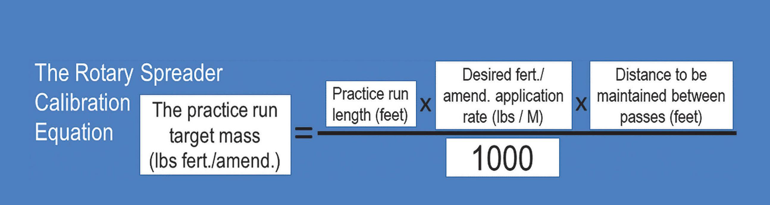
Figure 2
The second step of rotary spreader calibration
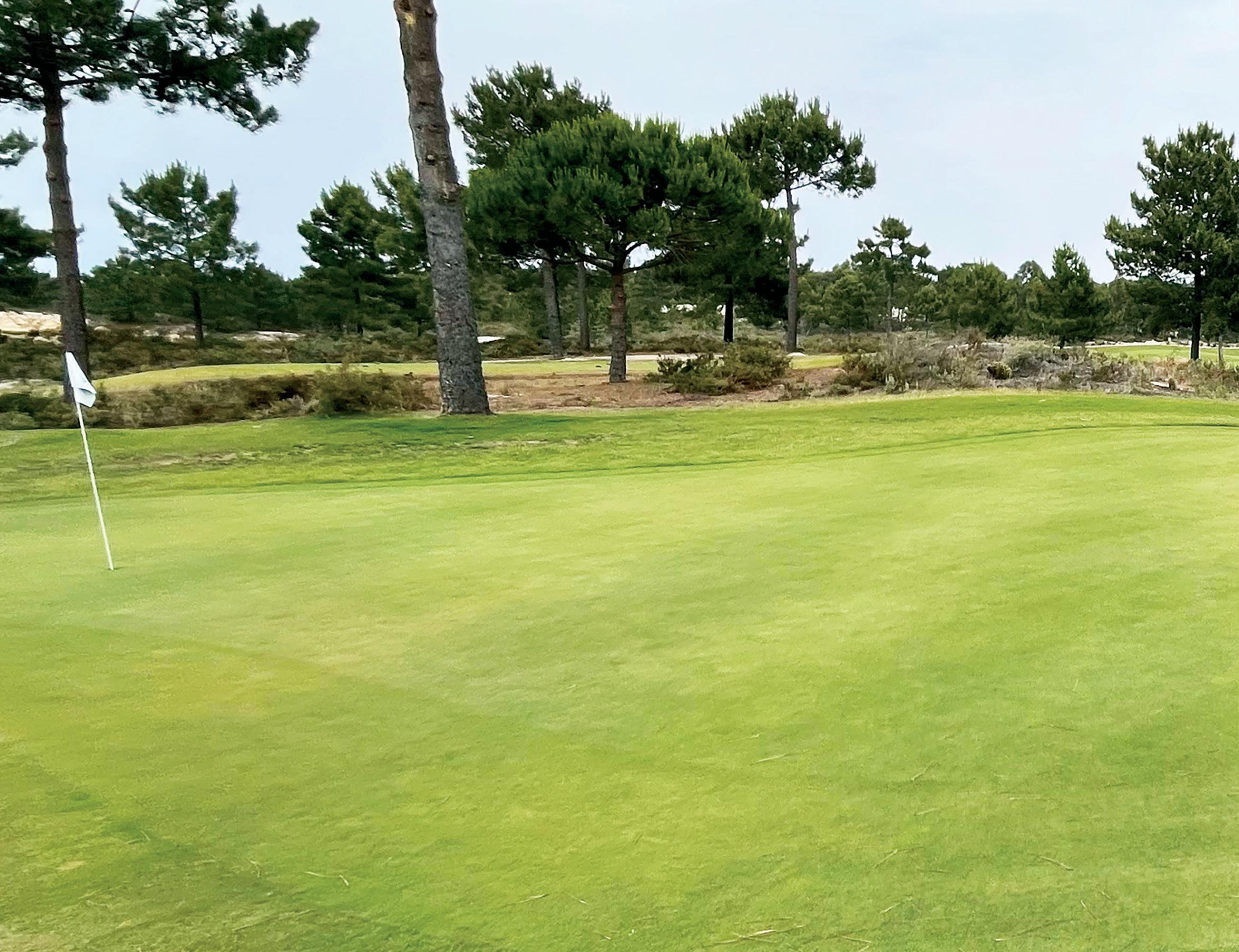
The next step in my rotary spreader calibration method is measuring the fertilizer specific treatment swath. It diverges from more commonly recommended approaches, but sensibly addresses a poignant question: Why does fertilizer application by a rotary spreader sometimes leave stripe artifacts (Figure 3)?

Figure 3
The answer(s) is one or both of the following:
1. Successive spreader passes, back and forth across the target area, were made too far apart.
2. When operated in the traditional back and forth manner, an asymmetric distribution of fertilizer from the spreader prevailed across the treatment swath; i.e., one side heavier than the other.
The opportunity for the first of these issues will certainly arise, while that for the second may or may not. The first reason stripe artifacts occur isn’t surprising given the only thing exceeding the number of approaches used to determine ‘the specific distance to maintain between passes’ is the number of ways to reference it. Such crafty monikers include: treatment band/swath/width, distribution band/swath/width, effective spacing, and effective swath width, among others. Over the 25 years I’ve instructed turfgrass students on this topic, I’ve consistently used ‘distance to be maintained between pass centers (feet)’ in my rotary spreader calibration equation (Figure 2). Perhaps this intuitive, straightforward terminology is what deters widescale adoption, but I can dare to dream and will continue using it.
The second step of my rotary spreader calibration method has practitioners assess the right-to-left symmetry of the treatment distribution as well as its swath in feet. Thus, successful completion should resolve both the above-mentioned causes of striping artifacts. The outcome of the asymmetry test determines whether a 100% or 200% overlap should be employed during the ultimate granular product application but does not influence determination of the distance to maintain between passes (feet).
Measuring the treatment swath is a critical step of rotary spreader calibration as explained by Mr. Lance Walheim of the National Gardening Association:
‘To use a broadcast spreader properly, you need to know how wide a band the spreader covers. If the directions that came with the spreader don’t indicate the width, put some fertilizer in the spreader and run the spreader over a short stretch of lawn to find out.’
Word, Mr. Walheim! Determining the treatment swath in feet is by no means a ‘separate’ or ‘optional’ step in the procedure. The treatment swath (feet) will vary by product, and in some cases by walking speed too, but is required for every unique combination of rotary spreader model and granular product to be applied. Mr. Walheim further states; ‘don’t measure the coverage on concrete unless you plan to sweep up the fertilizer.’
His middle name is ‘Butta’ because he’s on a roll! When the ultimate destination of the product is maintained turfgrass, this should be measured on maintained turfgrass. Measuring the treatment swath on smooth pavement increases spreader travel rate, boosts speed of the impellor disc rotation, and exaggerates the treatment swath; further contributing to stripe artifact by way of Issue #1. It will also extend the time needed to complete the spreader calibration task due to sweeping requirements.
Excepting the clean, dry rotary spreader and granular product to be applied, Figure 4 comprehensively depicts all the equipment required to calibrate a rotary spreader. No future surprises, it’s all there in full! Step 2 requires each of the two clean rectangular tarps be spread approximately 15 inches apart on an eligible, representative turfgrass system. Next, examine the rotary spreader and ensure the metal screen is set in position (Figure 5). Open the hopper gate and examine the gate openings on the hopper bottom. They should be approximately one-third open (Figure 6). If not, shut the hopper gate and follow the spreader instructions to adjust the hopper gate openings to an approximately one-third open position. Close the hopper gate, tighten the adjustment knob (for good measure), and carefully fill the hopper with 10 lbs of the desired granular product.
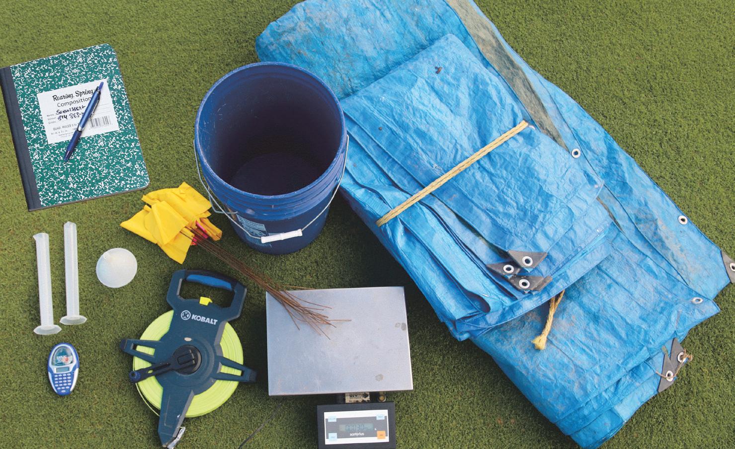
Figure 4
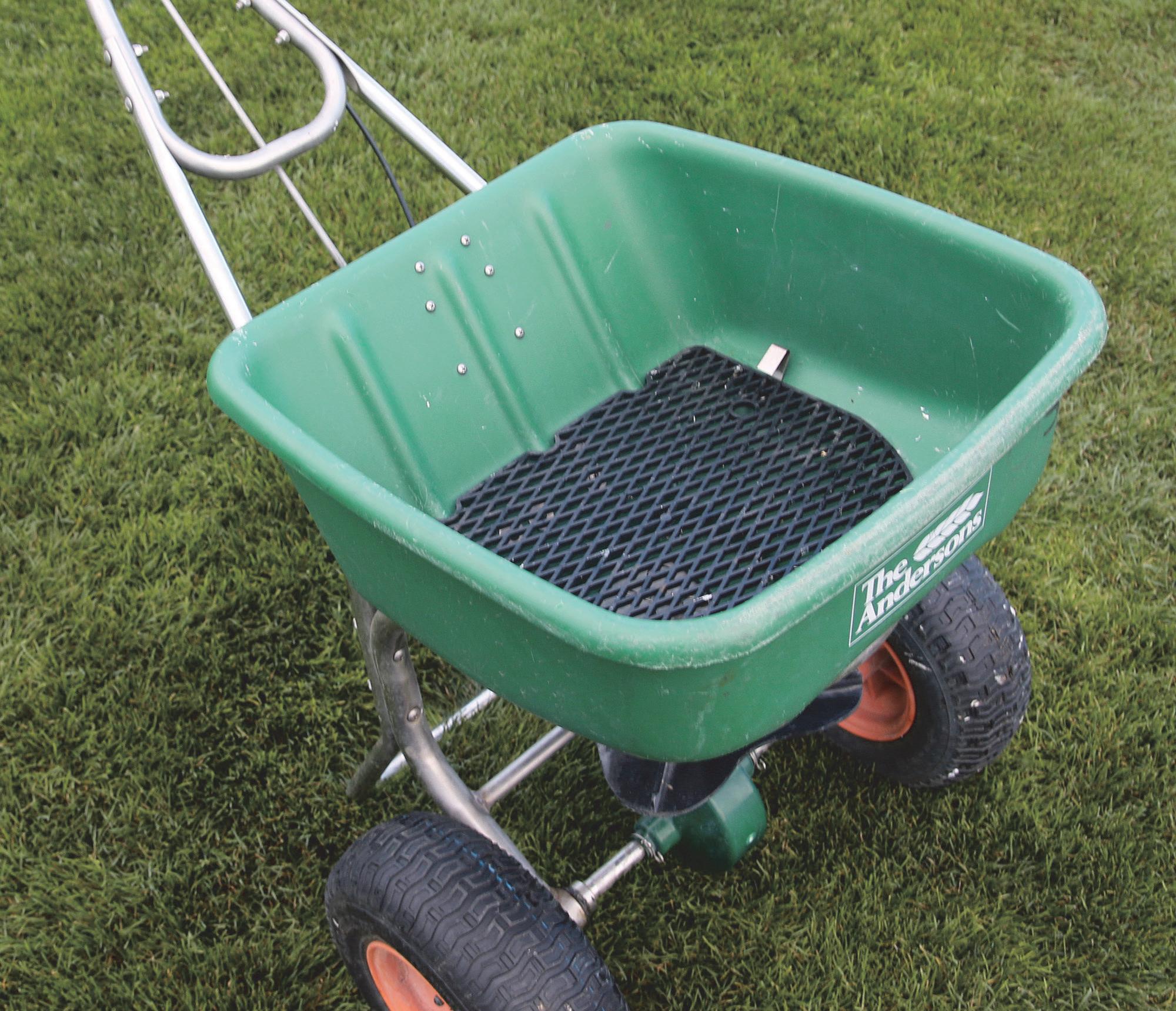
Figure 5
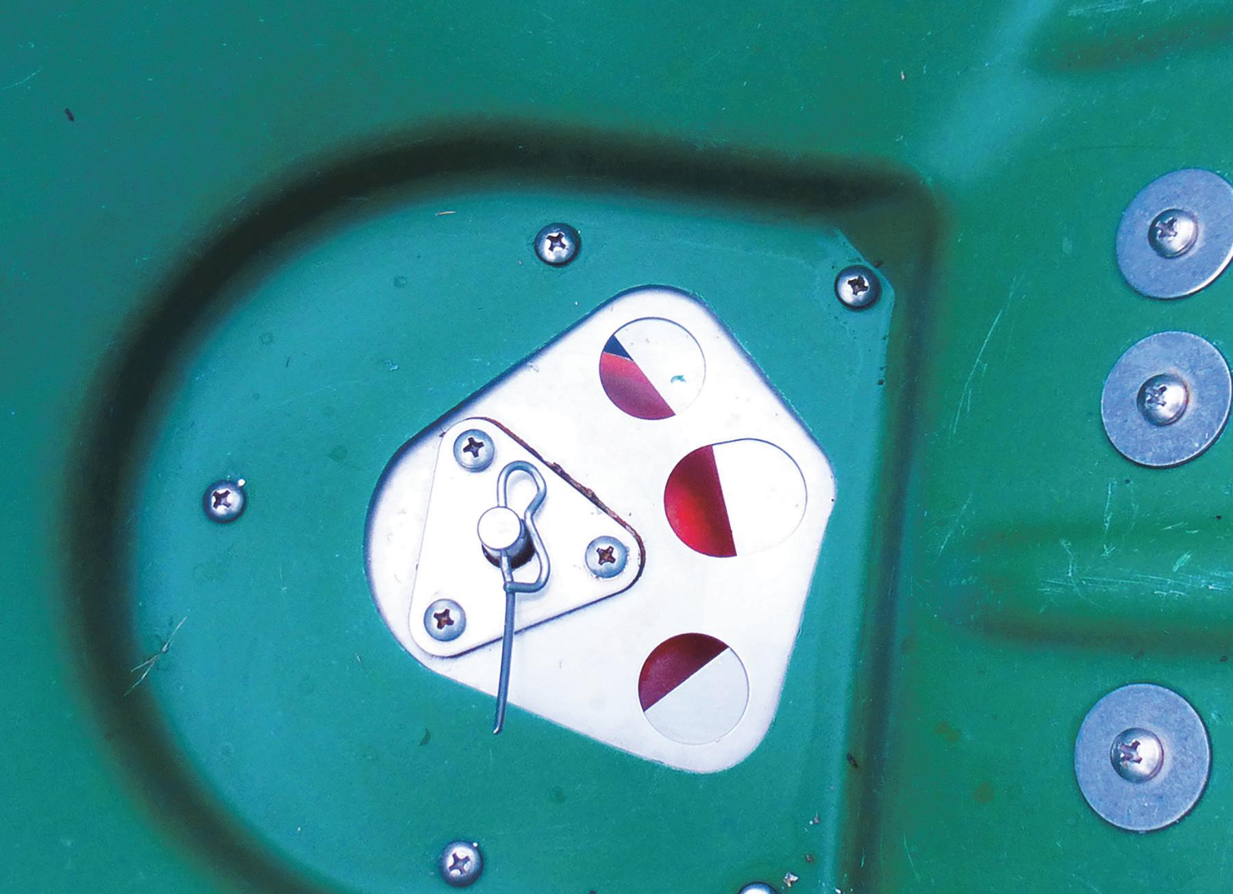
Figure 6
Next, the intended applicator positions the spreader 20 feet away from the tarps ( Figure 7 ) and begins walking at a safe yet briskly consistent pace toward the gap between the tarps. Once up to speed, and no less than 15 feet from the leading edge of both tarps, the applicator should firmly swing open the hopper gate lever while directing the spreader straight through the gap between the tarps ( Figure 8 ). Once aligned with the trailing edge of the tarps, the applicator can close the hopper gate lever. This process should be repeated, always travelling in the original direction, until a measurable quantity of granules is visible on both tarps.
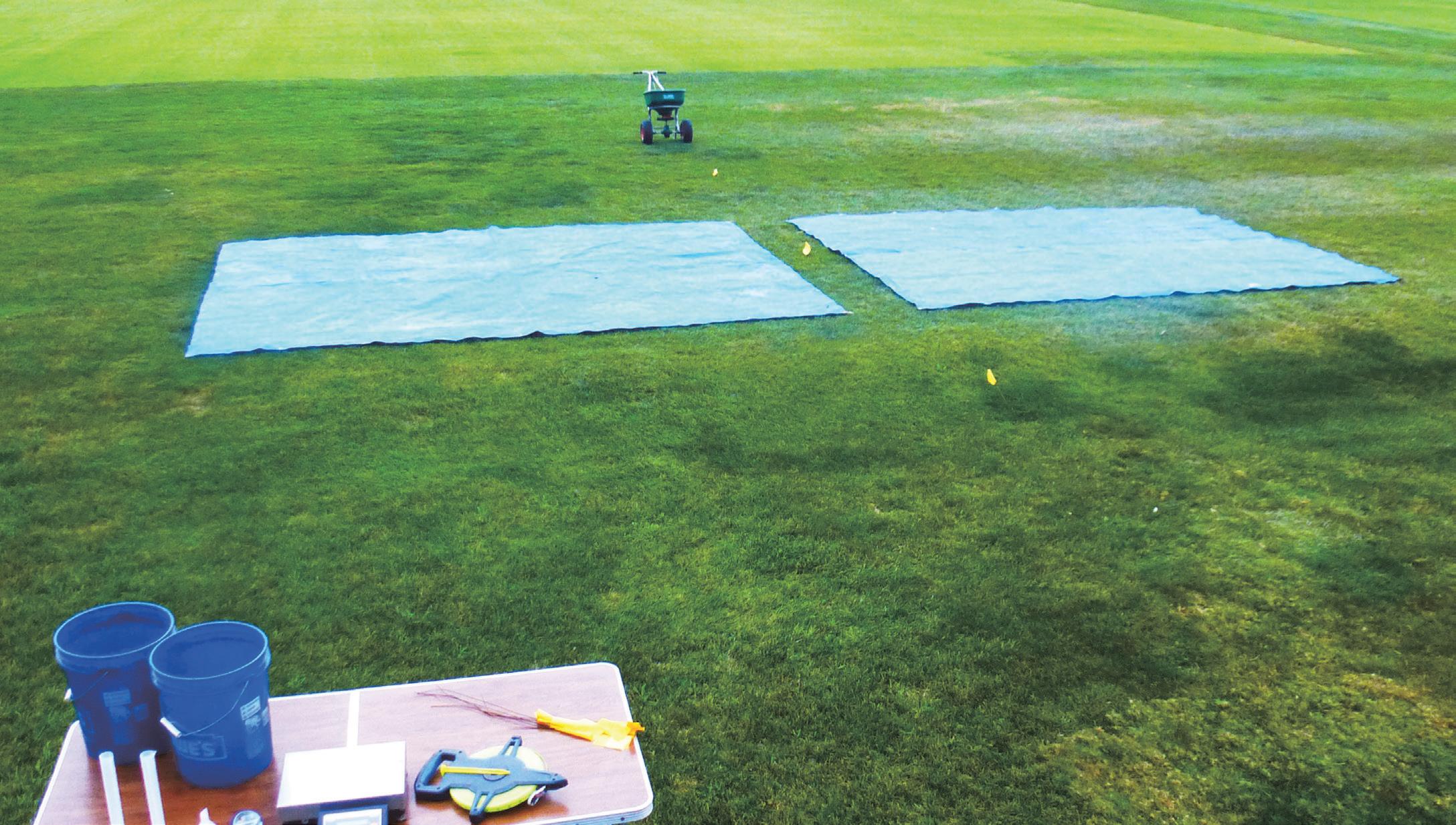
Figure 7

Figure 8
At this time, a measuring tape is used to determine the treatment swath in feet. The outer edge of granules on the tarp should not be considered the boundary of the treatment swath. Rather, it should be used as a guide to locate the outer edge of granules in the turfgrass (along the leading edge of each tarp). The boundary of granules in the turfgrass is what should be used for measurement. If the granules bounced across the tarp, then the outer edge of granules in the turfgrass will rest closer to the gap than the outer edge of granules on the tarp. Place a pin flag to denote the boundary, then repeat using the leading edge of the granules on the other tarp as a guide to locate the outer edge of granules in the turfgrass.
Once set, measure the distance between the two pin flags in feet (Figure 9), and record as the treatment swath. Then retrieve the pin flags and measuring tape. To complete Step 2, divide the treatment swath by two. For example, the treatment swath depicted in Figure 9 is 18 feet. One half the treatment swath is the distance to be maintained between pass centers, or 9 feet in this example. Yes, meeting a 100% overlap goal is just that easy (Figure 10).
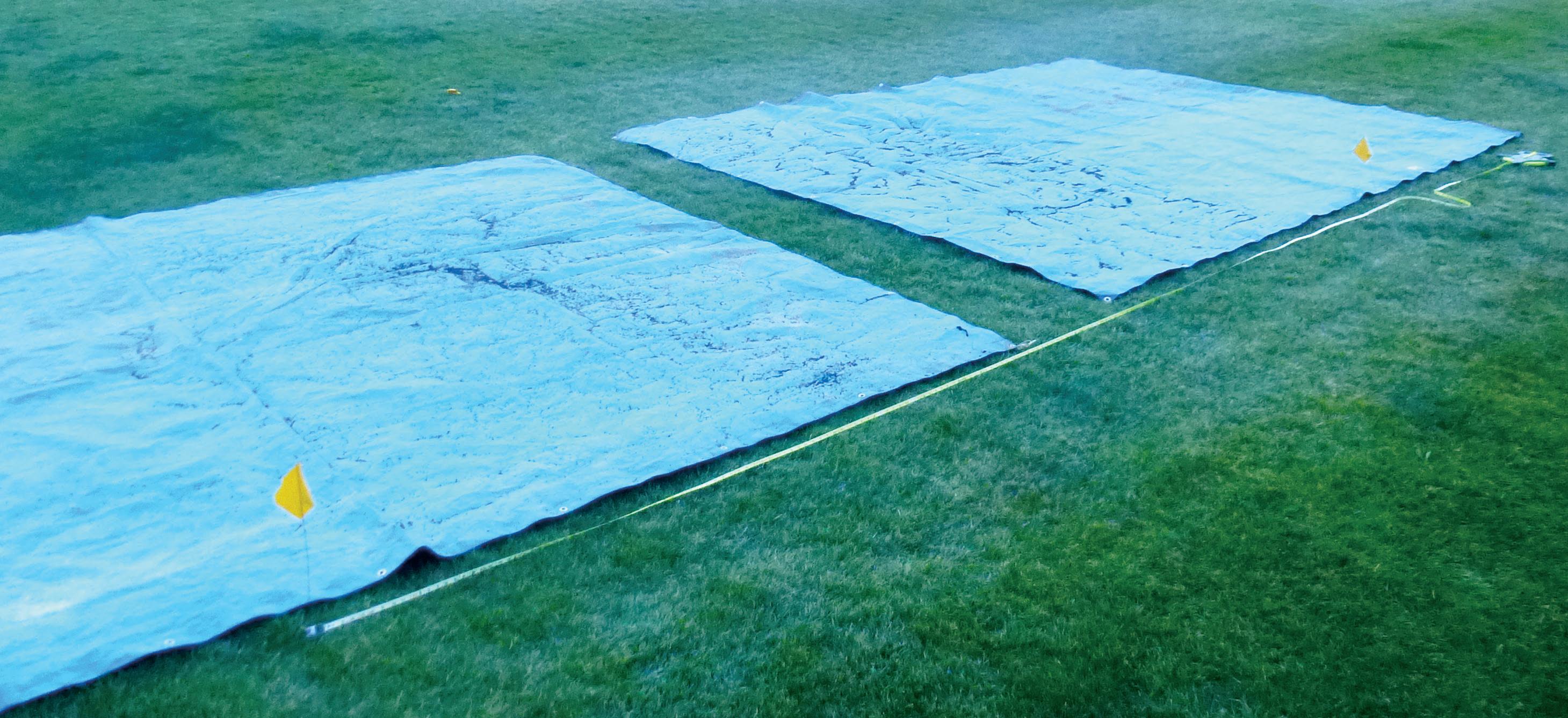
Figure 9
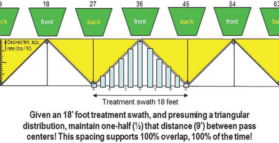
Figure 10
Ubiquitous alternatives to the above method are inextricably elaborate, yet poorly supported by experimentally-derived fertilizer distribution from commercial, walk-behind rotary spreaders. Given a treatment swath measuring 18 feet, enter the value of 9 feet into the ‘Distance to be maintained between passes (feet)’ slot of the rotary spreader calibration equation (Figure 11).
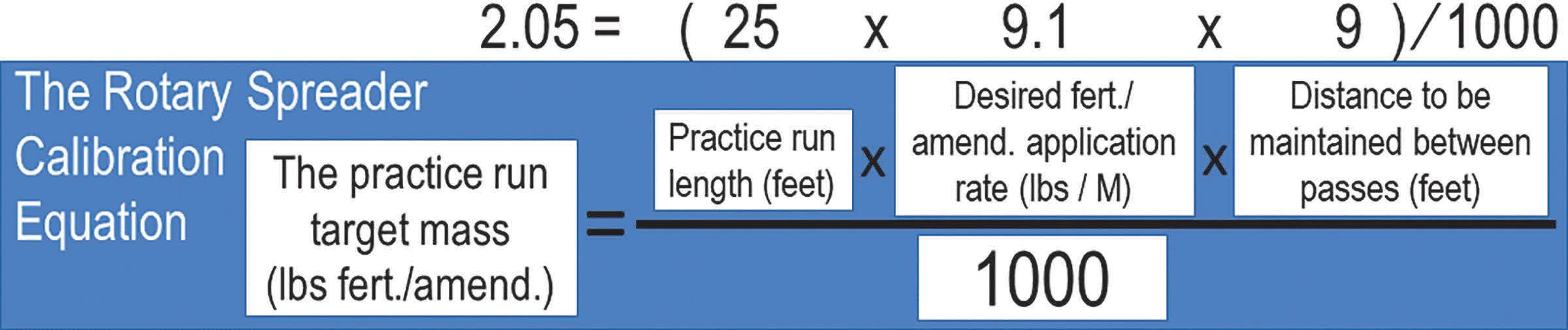
Figure 11
Many refer to this method as ‘spreading wheel-to-wheel’ and consider their view of it to be much simpler than mine. Sure, spreading wheel-to-wheel is a simplistic way of saying your next pass center will be made at the edge of where your last pass distributed fertilizer. Conceptually, the wheel-to-wheel directive would indeed amount to a 9-foot distance maintained between pass centers for the Figure 10 example. However, as simple as a directive that may be to one employee, it may prove operationally problematic for another.
As an assistant superintendent who trained teammates to calibrate a rotary spreader for their use, I felt comfortable identifying the finite distance to maintain between subsequent passes. Effective communicators give directions that are not open to interpretation. Likewise, when critical precision is ultimately required of the planned granular treatment, practitioners can use measuring tape and alternating-colored pin flags to ensure that 9-foot distance is in fact maintained between passes (Figure 12). Without belaboring it further, trust me when I say I’ve collected a lot of data, acquired even more, and run a hundred simulations. All other inanely-complex distribution sampling, plotting, and midpoint calculating steps will not prove more reliable a method as maintaining half the total treatment swath between passes, period. The more diligent the operator is about determining and maintaining this half the treatment swath distance between passes, the more successful the outcome.
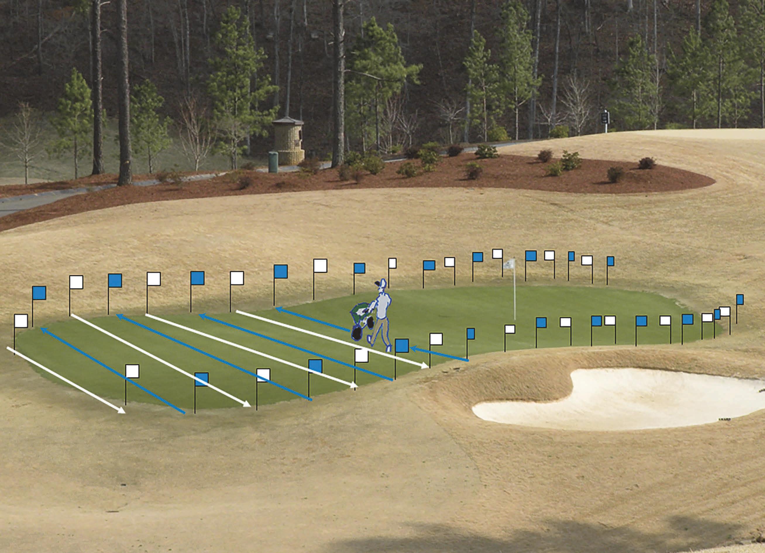
Figure 12
Now that you are convinced of that, grab one of the two clean buckets and carefully lift the corners of one tarp to collect all the granules along the middle of one edge. Position the bucket accordingly and transfer all granules into it, then set that granule-laden bucket safely aside on a stable surface. Repeat the process on the second tarp using the second clean bucket. If the mass of granules in each bucket resides within the operating range of your balance, then carefully determine each mass and record. Alternatively, the volume of granules collected from each tarp can be measured by transferring the granules into a graduated cylinder. Gently tap the filled cylinder to facilitate consistent settling and a uniform bulk density, then carefully determine each volume and record. This information will be used momentarily.
The next step is to mark out a practice run length on representative turfgrass. The length of the practice run should be no less than 25 ft but need not exceed 60 ft. I’ve noticed some industry YouTube videos encourage their subjects to determine the practice run length by dividing 1000 sq. ft. by the number of feet the spreader treatment swath is wide. These folks then go on to present a simplified equation, where the practice run target mass equals the desired fertilizer/amendment rate in lbs per M. Yet the spreader treatment swath width is never again mentioned.
So, allow me to briefly support my characterization of this recommendation as highly-suspect, or ‘sus’ as PSU students sometimes say. First, accurate balances and proportional properties of multiplication facilitate precise calibration at reduced scale, i.e., we don’t have to treat 1000 sq. ft. (M) in each practice run to calibrate our rotary spreader to lbs per M.
Second, using a practice run length equal to 1000 divided by the treatment swath width, for the purpose of setting the practice run target mass equal to the desired fertilizer/amendment rate, presumes the treatment swath width distance will be maintained as the distance between pass centers. And while a 0% overlap approach proves adequate when operating a drop spreader, expectations of further versatility are misguided. While all turfgrass scientists may not agree whether rotary spreaders apply granules in a semi-circular, triangular, or trapezoidal distribution across the swath width, I’m pretty certain none are betting the perfectly-rectangular horse.
Getting back on topic, next use paint or pin flags to mark at least one 25- to 60-foot practice run over representative turfgrass. Employ of a calibration kit (Figure 13) facilitates reuse of a single practice run as many times as necessary. If a calibration kit is not available, multiple practice run lengths will be required and any number will be treated by the product at a rate less or greater than the desired application rate. Frankly, it depends on how close your first hopper gate setting guess comes to delivering the target mass.
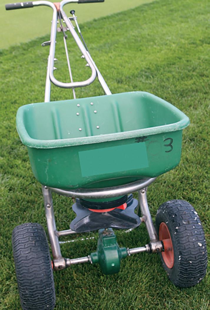
Figure 3 A
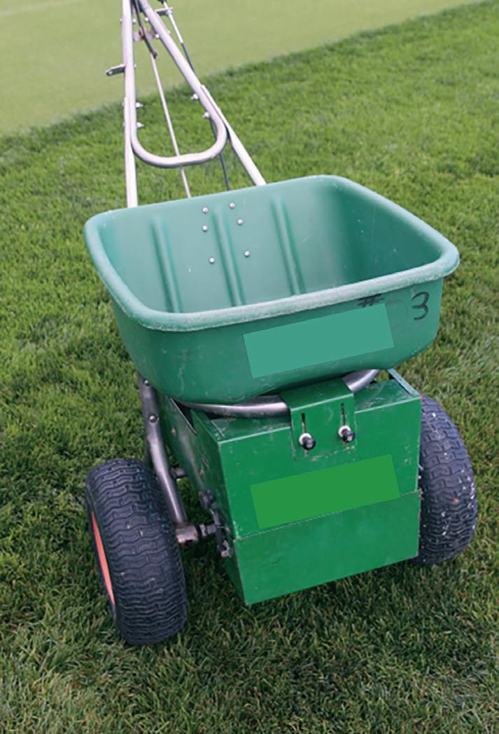
Figure 3 B
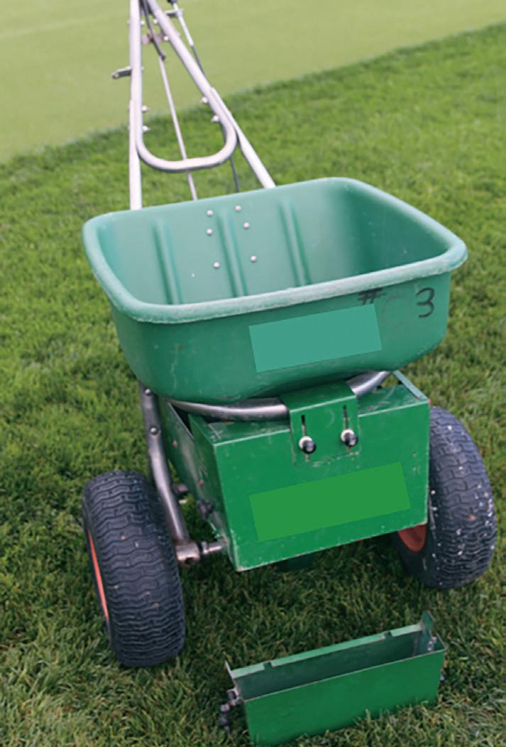
Figure 3 C
You will employ pin flags to avoid double treating practice run lengths. If calibrating your rotary spreader to apply a desired rate of pesticide, then you could really use a calibration kit! Otherwise, the area receiving product from iterative practice runs must be accurately described in pesticide application records; and treated areas may not be re-treated in a manner prohibited by the label. Again, one can never be certain how many practice runs will be required, but the number typically exceeds one.
The third step of rotary spreader calibration
Before I get too far ahead of myself, let’s suppose several practice runs 25 feet in length will be marked in the representative turfgrass area. Insert this value into the ‘Length of practice run (feet)’ slot of the rotary spreader calibration equation and solve for ‘Target lbs fertilizer applied in practice run.’ The resulting target fertilizer mass to be applied over a 25-foot practice run is 2.05 lbs K-Mag (Figure 11). We have now completed over half the rotary spreader calibration steps. A remaining task is committing to either 100 or 200% overlap. Committing to 200% overlap is the more admirable option but requires twice as many traversing passes when making the planned granular treatment. The information I use in the decision rule, and encourage the readers to use as well, is the right-to-left distribution of granules as determined by the tarp collections.
If the masses or volumes of granules collected from the adjacent tarps were identical (or nearly), then a 100% overlap will suffice in preventing stripe artifacts. This means the calculated ‘practice run target mass= 2.05 lbs K-Mag fertilizer)’ should be employed in the final step (#4).
If the masses or volumes of granules collected from the adjacent tarps were dissimilar; then you may have options for resolving this issue.
If your rotary spreader has a distribution adjustment cone between the hopper and impellor disc, then you can consult the spreader manual and follow the instructions they provide for centering the distribution swath. That’s your Option #2. Using two tarps, this will prove a time-consuming and iterative process without assurance of rewarding outcome.
Using eight to sixteen ‘cake pans’ or ‘egg cartons’ spread across pavement to iteratively center the treatment swath defers a notable sweeping commitment, and is without question the most ludicrously impractical suggestion I have typed this year.
If you agree, or your rotary spreader does not feature a distribution adjustment cone, then consider Option #1:
Calculate the ‘asymmetry ratio’ by dividing the bigger tarp collection value by the smaller. When employing 100% overlap, the extent to which this asymmetry ratio exceeds 4/3 (1.33) correlates directly to the likelihood of striping by way of Issue #2. Thus, to prevent stripe artifacts, practitioners are suggested to employ a 200% overlap when the asymmetry ratio exceeds 1.33. This means the ‘as calculated’ practice run target mass is then further divided by 2, which makes sense given twice as many passes will ultimately be made across the treatment area.
In our example, 247 mL of fertilizer was collected from one tarp and 185 mL collected from the other (Figure 14); resulting in an asymmetry ratio of 247/185= 1.34. Thus a 200% overlap should be employed, making 2.05∕2= 1.025 lbs K-Mag the ‘practice run target mass (lbs fertilizer)’ goal of the final step.
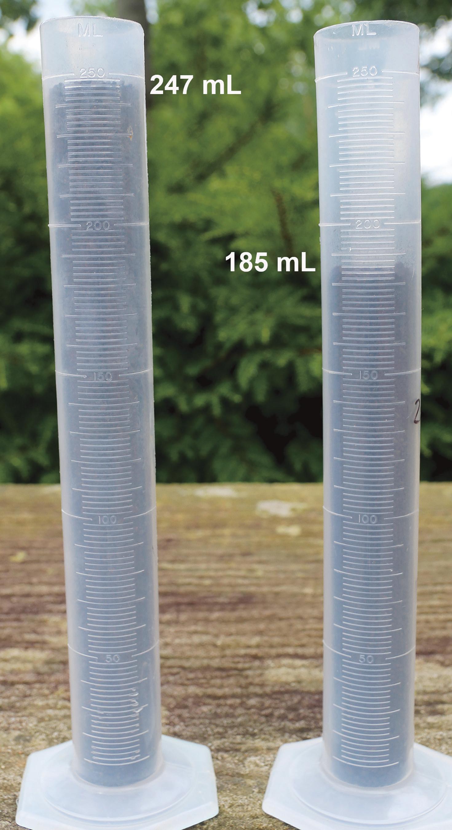
Figure 14
The final step of rotary spreader calibration
Now it is time to iteratively confirm the hopper gate setting satisfies the desired application rate. There are three general ways to do this, selection of the most ideal method will depend on your specific rotary spreader and available ancillary equipment.
I. Volume replacement procedure (good for large, mounted, or tractor-drawn spreaders)
STEP 1. Set the spreader on a (suspected) desirable setting, making sure spreader is off (closed).
STEP 2. Fill the spreader hopper full, or to a clearly marked and repeatable level, with your fertilizer.
STEP 3. With the spreader, begin walking at a typical and constant rate and open the hopper gate at the marked/ flagged starting point, continue over the practice run length, and close the spreader at the appropriate end point.
STEP 4. Return the spreader to the scale vicinity.
STEP 5. Tare a bucket, fill it with the fertilizer material, and weigh and record the material mass.
STEP 6. Use the fertilizer in the bucket to refill the spreader hopper to the original level (Step 2).
STEP 7. Weigh the fertilizer remaining in the bucket.
STEP 8. By subtraction, determine the mass of fertilizer spread while walking. This is fertilizer mass applied per linear distance (at previously walked speed, NOT ANY speed).
STEP 9. Determine if more or less than the target mass was applied, adjust the hopper gate setting accordingly, and repeat.
II. Indirect mass (or remainder) procedure (good for small spreaders that can easily be emptied)
STEP 1. Set the spreader on a (suspected) desirable setting, making sure spreader is off (closed).
STEP 1. Tare a bucket and fill it with the fertilizer material, then weigh & record the material mass.
STEP 3. Carefully, transfer all the fertilizer to the spreader hopper.
STEP 4. Begin walking at a typical and constant rate with the spreader, open the hopper gate at the marked/ flagged starting point, continue over the practice run length, and close the spreader at the appropriate end point.
STEP 5. Carefully transfer the fertilizer remaining inside the spreader hopper to the original tared bucket.
STEP 6. Weigh the fertilizer in the bucket and record its mass.
STEP 7. The difference in fertilizer mass, from before walking the practice run to after, is the fertilizer mass applied per linear distance (at previously walked speed, NOT ANY speed).
STEP 8. Determine if more or less than the target mass was applied, adjust the hopper gate setting accordingly, and repeat.
III. Direct mass measurement (best, but REQUIRES a PENN PRO calibration kit)
STEP 1. Set the spreader on a (suspected) desirable setting, making sure spreader is off (closed).
STEP 2. Install the enclosure kit PROPERLY (covering the spinning rotor plate/impellor disc).
STEP 3. Remove and empty collection pan, place pan on balance, tare to zero, return pan to kit enclosure.
STEP 4. Fill the spreader with an ample quantity of your fertilizer.
STEP 5. Begin walking at a typical and constant rate with the spreader, open the hopper gate at the marked/ flagged starting point, continue over the practice run length, and close the spreader at the appropriate end point.
STEP 6. Carefully collect all the material into the detachable collection pan, ensuring all prills have been collected from the calibration kit enclosure! Failure to recover all fertilizer from the kit will result in improper calibration.
STEP 7. Detach collection pan and weigh. This is the fertilizer mass applied per linear distance (at previously walked speed, NOT ANY speed).
STEP 8. Determine if more or less than the target mass was applied, adjust the hopper gate setting accordingly, and repeat.
Review: When is using a 200% overlap (spreading at ½ rate in two perpendicular directions) appropriate?
1. When the rotary spreader distribution is skew, or heavier on one side than the other; i.e., the asymmetry ratio exceeds 1.33.
2. When applying seed (or a seed/amendment blend) to a bed prepared for turfgrass establishment.
3. When spreading fert./amend. on a windy day.
4. When the desired application rate (lbs fert./amend. per M) exceeds the maximum rate of delivery by the spreader. For instance, when you seek to apply 35 lbs pelletized limestone / M but can only apply 19 lbs pelletized limestone / M with the hopper gate wide-open (and at your typical walking speed). In this event, do not slow down your walking speed to achieve a 35 lbs pelletized limestone / M rate! Instead, maintain your original walking speed (and treatment swath) and calibrate the spreader to apply ½ the original rate (1/2 of 35), or 17.5 lbs pelletized limestone / M. Apply the 35 lbs pelletized limestone / M by making two perpendicular passes over your target area.
