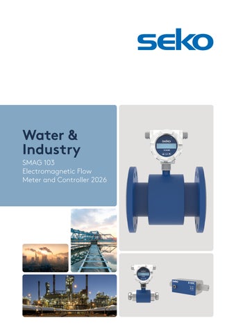
Water & Industry SMAG 103 Electromagnetic Flow Meter and Controller 2026
2
Water & Industry Product Catalogue 2026
SMAG 103
Electromagnetic Flow Meter and Control unit
3
SMAG 103 Electromagnetic Flow Meter and Control Unit
Product Overview
Dimension [mm] Nominal pressure [bar]
SMAG 103 M
SMAG 103 S
SMAG 103 C
DN15 - DN600
DN25 - DN80
DN6 - DN20
10 - 40
16
25
4
Water & Industry Product Catalogue 2026
SMAG 103 Electromagnetic flow meter and control unit SMAG 103 is a professional electromagnetic flow meter and controller that’s ideal for measuring conductive fluids, wastewater and other liquids across multiple applications. Built with high-grade materials such as Hastelloy C4, carbon or stainless steel, rubber, PTFE and PFA, SMAG 103 withstands challenging conditions including liquids up to 170°C. With application uses across water treatment, mining and refineries, food, energy generation, wastewater treatment and chemical production, SMAG 103 meets the needs of modern water management systems and represents one of SEKO’s most versatile solutions for high-precision measurement. The ATEX version has been designed with a robust construction, an all-stainless steel design and remote control without a display unit. This makes it an unbeatable flowmeter for any application that requires durability and longevity.
Applications The versatile SMAG 103 is suited to multiple water-treatment applications, including: • • • • •
Water treatment Mining and refineries Energy generation Chemical production Wastewater treatment
5
SMAG 103 Electromagnetic Flow Meter and Control Unit
Features & benefits Municipal Water Treatment •
Sludge and water treatment
Industrial Processes •
Energy industry: generation and distribution
•
Extraction industries: quarries and mines (ATEX II 1G EX Mark)
Chemical Industry •
Control of civil and industrial wastes
•
Chemical dosing control
Drinking Water •
Measurement of potable water
Specification Power
230 VAC (50/60 Hz), 24 VAC/ VDC with polarity reversal protection
Type of electronics
Head (H – standard), front (F), panel (P) versions
Design
Compact (up to Tmax 90 °C); Separated (standard cable length 3 m)
Diameter nominal
DN 10 ÷600
Lining material
Rubber, PTFE, PFA, ETFE
Electrode material
Hastelloy C4 (std), Titanium, Tantalum
Frame
All-welded
Sensor material
• •
Process connections
• • • •
Flanged using stainless steel (AISI304) and structural steel with polyurethane coating Threaded, Sandwich, food grade using stainless steel Flanged DIN (EN1092) – carbon or stainless steel Sandwich Threaded (EN ISO 228-1) Food grade (DIN 11851 fitting, clamp)
Pressure
PN10, PN16, PN25, PN40
Min. conductivity of the measured fluid
20 μS/cm
Flow meter measuring range (Qmin/Qmax)
Bi-Directional for 0.2 - 12 m/s (1/60); 0.12 - 12 m/s (1/100); 0.06 - 12 m/s (1/200)
Flow meter accuracy
Accuracy up to 0.5 %, repeatability up to 0.2 %
Pressure loss
Negligible
Additional electrodes
Grounding and detection electrodes for empty piping
Empty piping detection
Yes
Display unit
LCD 2×16 characters; backlit
Controls/settings
• •
Outputs
• •
2 × external button (viewing values) 3 × internal button (viewing + parameter setting) Impulse/flow switch (max. 400 Hz), 4-20 mA, Interface RS485 (protocols M-BUS/Mod-Bus) (Impulse and current outputs are passive with a possibility of being powered from internal power supply of the meter)
Max. ambient temperature
55 °C
Protection degree
IP65, IP67, IP68 (std)
6
Water & Industry Product Catalogue 2026
SMAG 103 Electromagnetic flow meter and controller The SMAG 103 meter is based on measurement principle by Faraday’s electromagnetic induction law according to which an electric voltage is induced during the flow of a conductive liquid through the flow meter magnetic field. This is picked up by two electrodes in direct contact with the measured medium and evaluated in the electronic unit. The SMAG 103 type of induction meters are suitable exclusively for measurement of volumetric flow of electrically conductive liquid substances with a minimum conductivity of 20 uS/cm (at a lower conductivity, upon agreement with the manufacturer). Meters are designed for flow measurement where the velocity of liquid is in the range of 0.01 - 12 m/s. The best measurement accuracy can be obtained in the range of 1 - 10 m/s.
SMAG 103 M Size and connections
DN15 - DN600 (Flange EN 1092-1)
Nominal pressure
10 - 40 bar (64 bar on request)
Lining
PTFE and rubber
Body material
Carbon steel with electrodes in Hastelloy C4
Temperature of liquid Compact Design: 70°C for rubber; 90°C for PTFE/ETFE Remote Design: 70°C for rubber; 140°C for PTFE/ETFE (170°C for High construction)
SMAG 103 S Size and connections
DN25 - DN80 (Food thread DIN 11851)
Nominal pressure
16 bar
Lining
PFA
Body material
Carbon steel with electrodes in Hastelloy C4
Temperature of liquid Compact Design: 90°C for PFA
SMAG 103 C Size and connections
DN6 - DN20 (Thread ISO 228-1)
Nominal pressure
25 bar
Lining
PVDF
Body material
SS304 with electrodes in SS316L
Temperature of liquid Compact Design: 70°C for PVDF
7
SMAG 103 Electromagnetic Flow Meter and Control Unit
SMAG 103 key code Type of electronics S3
S 103 - Head version (H-standard)
S4
S 104 - Panel version (P)
S5
S 105 - Front version (F) Product M
Flow 38 / Flow 45 (flanged)
S
Flow 38 (DIN11851)
D
Flow 38 MID Cert. (Logo COMAC CAL)
C
Flow 32 (EN ISO 228-1)
X
Flow 33 Ex (ATEX II 1G Ex ia IIC T6) - pending Certification Design (A) Y
A1 = Compact @ 70°C
P
A2 = Separated @ tmax 140°C (cable length 3 - 30m)
F
A3 = Separated @ tmax 80°C (cable length 3 - 30m) Diameter nominal 0010
DN 10
0015
DN 15
0020
DN 20
0025
DN 25
0032
DN 32
0040
DN 40
0050
DN 50
0065
DN 65
0080
DN 80
0100
DN 100
0125
DN 125
0150
DN 150
0200
DN 200
0250
DN 250
0300
DN 300
0350
DN 350
0400
DN 400
0500
DN 500
0600
DN 600 Pressure A
C5 = PN64 DIN (64 bar)
B
C4 = PN40 DIN (40 bar)
C
C1 = PN10 DIN (10 bar)
D
C3 = PN25 DIN (25 bar)
E
C2 = PN16 DIN (16 bar)
F
C6 = PN100 DIN (100 bar) Lining (D) 1
D1 = Hard/Soft Rubber (ebonite)
2
D4 = PTFE
3
D5 = PFA (high-performance) Connection (B) B
B1 = Flanged DIN (EN 1092)
E
B1 = Flanged DIN (ANSI 150)
F
B1 = Flanged DIN (ANSI 300)
H
B3 = Threaded (EN 10226-1)
C
B5 = Clamp (DIN 32676)
D
DIN 11851
G
UNI ISO 228/1 (Male GAS threaded) Electrodes (E) 1
E1 = Stainless Steel 316 Ti
2
E4 = Tantalum
3
E2 = Hastelloy C4
4
E3 = Titanium Power Supply (H) A
H1 = 110 - 230 VAC (50/60 Hz)
B
H2 = 24 VAC/VDC
E
Battery pack 12/24 VAC/DC HIGH PERF. Measuring Range -Qmin/Qmax (I) 0
I1 = 1/60
1
I2 = 1/100
2
I3 = 1/200
V
For further use Electrical Output 0
G1 = Impulse/switch (standard)
A
G2 = Imp/sw + 4-20mA
B
G3 = Imp/sw + RS485
C
N.U.
D
G5 = Imp/sw + 4-20mA + HART
E
G4 = Imp/sw + 4-20mA + RS485
F
G6 = Imp/sw + 4-20mA + HART + RS485 IP grade (F) 0
IP65
1
IP67
2
IP68 (3 m only remote version) Cable Lenght/Others
S3
M
Y
0100
B
2
B
3
A
0
E
2
00
Not Present (only compact)
05
5 meters
10
10 meters
30
30 meters (maximum value)
EM
Mid Certification
XX
Others
00
Globally Present, Locally Active
Twenty-three national SEKO companies across six continents means that, wherever you are, you enjoy the same exceptional level of service as every SEKO customer around the world. And an accredited partner distributor network allows us to provide local customer support in over 120 countries, so you benefit from region-specific knowledge and rapid delivery of goods as well as worldclass after-sales service and technical assistance.
SEKO Hub A world of SEKO in one For everyone from buyers and engineers to end users, SEKO Hub is the ultimate all-encompassing platform that brings you to the heart of SEKO and gives you what you need when you need it. Bringing together essential documents such as manuals, case studies, data sheets and brochures as well as tutorial videos, favourite products, an appointment booking system and so much more, SEKO Hub is a central personalised platform to revolutionise the way you work. SEKO Hub is available online or via app, so you’re never without it whether you’re at work, at home or on the move. It’s your home for the complete SEKO experience, so join SEKO Hub and make our world a part of yours.
SEKO products are intended for professional use in industrial applications only and are not available for domestic or retail sale. SEKO reserves the right to amend and change specifications without prior notice. All pictures shown are for illustration purpose only. Actual product may vary due to product enhancement. Published data may be subject to change. © 2026 SEKO, Layout and origin: UK, 850003 WTCATA-SMA EN V04
seko.com