September 2026
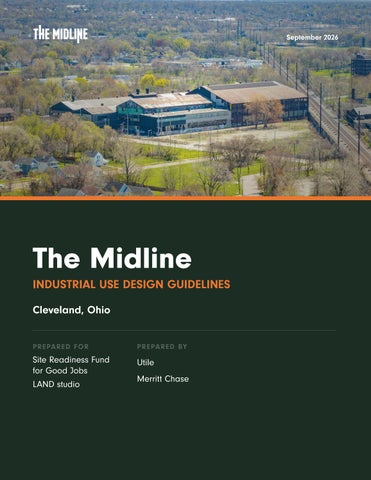
The Midline INDUSTRIAL USE DESIGN GUIDELINES Cleveland, Ohio PR E PA R E D F OR
P R EPAR E D BY
Site Readiness Fund for Good Jobs LAND studio
Utile Merritt Chase
LEGEND Midline Boundary Industrial Use Active Use (Lobby, Commercial, etc.) Mixed-Use / Residential Infill Open Space Midline Greenway
2
THE MIDLINE | Industrial Use Design Guidelines
TH E M I D LI N E • I N DU STRIA L U S E DESIGN GUIDELINES
Contents 01
Introduction
02
Site Layout
03
Landscape Design
04
Building Design
05
Additional Guidelines
04
Purpose, Principles, Key Terms, Street Activation Hierarchy
10
Site Placement Overview, Integrating the Greenway
16
Frontage Zone, Stormwater Management, Planting Buffer
20
Facade Articulation, Building Signage
30
Front and back cover photos by Patrick Fenner. All other photo credits can be found on pages 32-33.
Contents
3
SEC TI O N 0 1 • I NTRO D UCTI O N
Purpose These Guidelines complement the Midline Master Plan and serve three main purposes: 1. Guide building and site design Establish clear expectations for site planning and design quality to guide SRF’s conversations with companies and developers. 2. Design the District as one place Promote a visually appealing and coherent 21st century business district across industrial buildings, associated open space, the Midline Greenway, and the broader public realm. 3. Inform new zoning Establish draft dimensional standards that can inform a new zoning overlay or a version of the Cleveland Neighborhood FormBased Code specific to the Midline Business District. The Guidelines establish design principles that apply across the District, but each Development Zone’s unique size, shape, and adjacencies will impact how the principles are applied. For examples of how these principles play out on individual sites, please refer to the Midline Test-fit Cutsheets document.
4
THE MIDLINE | Industrial Use Design Guidelines
MASTER PLAN FRAMEWORK The Framework transforms 350+ acres of underutilized land into a connected business district and greenway.
Introduction
5
SEC TI O N 0 1 • I NTRO D UCTI O N
Governing Principles The Design Guidelines are built on these underlying design principles: 1. Create a consistent street wall and streetscape across the district (as opposed to parcel-by-parcel customization).
6
2. Integrate the Midline Greenway, where applicable, with added setbacks, enhanced landscapes, and building articulation. 3. Prioritize active human-centered uses close to and facing public streets (such as lobbies, offices, and accessory retail).
4. Balance pedestrian and bicycle accommodations with truck access. 5. Leverage stormwater management as visual amenity. 6. Buffer industrial uses from existing residential fabric.
THE MIDLINE | Industrial Use Design Guidelines
Applicability & Key Terms Applicability
Key Terms
The Cleveland Midline Industrial Use Design Guidelines apply to the following industrial uses and their accessory uses. These use categories align with those in the Neighborhood Form-Based Code.
The terms below are common to most Form-Based Codes; those highlighted in orange have been tailored to industrial uses in the Midline Business District.
• Light Industrial • Makerspace • Research & Development • Warehouse & Distribution • Accessory Uses (such as office and retail)
ACTIVE USE Human-centered use, such as lobby, office, commercial, retail, employee common areas, makerspace, etc. FACADE The exterior wall of a building oriented in whole or in part toward a front lot line or the Midline Greenway. FACADE BUILD OUT The ratio of the facade width to the lot width, calculated by dividing the cumulative facade width by the lot width. FENESTRATION The openings in the facade of a building, including windows and doors. FRONTAGE ZONE The area of a lot between the building facade(s) and the Active-Street front lot line(s), extending fully to each side lot line(s), or the area between a building and the Midline Greenway where the two are located within 30 ft of each other.
Introduction
FRONTAGE ZONE TYPE A distinct combination of open space and landscape design features located in the Frontage Zone. LOT LINE The boundary that legally and geometrically demarcates a lot. LOT LINE, FRONT Any lot line abutting a thoroughfare, excluding an alley. LOT LINE, SIDE Any lot line other than a front or rear lot line. LOT LINE, REAR Any lot line which is parallel to or within forty-five (45) degrees of being parallel to a front lot line, unless that lot line is a side lot line of an abutting lot. LOT WIDTH The length of the front lot line of a lot. PRINCIPAL ENTRANCE The addressed entrance to a building or commercial space.
7
SEC TI O N 0 1 • I NTRO D UCTI O N
Street Activation Hierarchy Prioritize Active Streets and the Midline Greenway The Guidelines establish a Street Hierarchy in the District to guide how sites should respond to different public streets, placing the highest design expectations on Active Streets and the Midline Greenway. All highlighted streets in orange (on the map at right) are designated as Active Streets, intended to
be the most activated, walkable/ bikeable, and visually appealing. All other public streets are considered Secondary Streets, intended for general circulation and servicing access. For the purposes of this document, the Midline Greenway is conceived of as a public street and is situated between Active Streets and Secondary Streets in this hierarchy.
Greenway are the most visible and important in terms of the district’s urban design goals and are therefore subject to more design guidelines. Where a lot fronts on multiple Active Streets, the project proponent may choose only one (or more) as the designated Active Street(s) for the purposes of following the design guidelines in this document.
Buildings and open spaces along Active Streets and the Midline
Applicable Design Guidelines Maximum Front Setback
Active Street Midline Greenway Secondary Street
•
Minimum Facade Buildout
Curb Cut Limitation
Active Use Placement
Principal Entrance Placement
Frontage Zone Type Requirement
Building Facade Articulation
Minimum Parking Setback
Street Buffer Requirement
• • • • • • • • • • • • • • • • • •
= Where a design guideline applies wholly or conditionally
= Where a design guideline does not apply or is not applicable
ACTIVATION HIERARCHY The more activation a street is intended to support, the more design guidelines apply along it.
8
THE MIDLINE | Industrial Use Design Guidelines
Active Street Midline Greenway Secondary Street
Street Hierarchy
Introduction
9
SEC TI O N 0 2 • S ITE L AYO U T
Site Placement Overview Engage the street, hide the parking/loading apron, and buffer the edges To promote a consistent street wall and an enhanced public realm, particularly along designated Active Streets, industrial buildings should be placed close to the street, built out to
Plan View
a minimum percent of the lot width, and programmed with ground floor active uses facing that street. Parking and loading aprons should be placed to the side or rear of the building, with curb cuts located only on Secondary Street(s), where possible. Stormwater management areas can be placed anywhere on site, but should be designed as a visual amenity where
Place parking, loading, and service areas to the side and rear
Buffer parking, loading, and service areas from streets and neighbors
Design stormwater detention as visual amenity
Place industrial buildings within 10 to 20 feet of the street
10
visible from the public realm. Lastly, the site should provide a planting buffer between parking/loading aprons and public streets, and along side and rear lot lines.
Place Active Uses on Active Streets
THE MIDLINE | Industrial Use Design Guidelines
Building Placement A Front Setback Active Street (min/max) Secondary Street (min) B Side Setback (min) Abutting a non-R Dist.
Parking/Loading Placement 10 ft / 20 ft 10 ft 25 ft
Abutting an R District C Rear Setback (min) Abutting a non-R Dist.
40 ft
Abutting an R District
40 ft
15 ft
Active Street
60%
Secondary Street
None
Building Massing
Side or Rear Only
D Front Setback (min) Active Street Secondary Street E Side Setback (min) F Rear Setback (min)
Facade Line 10 ft 8 ft 8 ft
Curb Cut Placement Location
Facade Build Out (min)
Height in Stories (max) Height in Feet (max)
Location
Side or Rear Only
Distance Between 200 ft Curb Cuts (min) G Curb Cut Width (max) If serving trucks 28 ft If not serving trucks 24 ft
4 Stories 85 ft
Aerial View Place parking, loading, and service areas to the side and rear
Site Features Placement Stormwater Front, Side, Detention Area or Rear Location Perimeter Planting Buffer (min) N/A: See From Active-Street A Frontage Front Lot Line Zone Types From Secondary10 ft Street Front Lot Line E, From Side/Rear Lot 8 ft F Line
Building Features Placement Active Use Location Principal Entrance Location
Only on Active Street or within 30 ft of Greenway 20 ft
Active Use Depth (min) Active Use 60% Fenestration (min)
Buffer parking, loading, and service areas from streets and neighbors
Design stormwater detention as visual amenity
Place Active Uses on Active Streets Place industrial buildings within 10 to 20 feet of the street
Site Layout
11
SEC TI O N 0 2 • S ITE L AYO U T
Site Placement — other Lot Types Interior Lot Alternate Layout (Rotated 90°)
Place Active Uses on the Active Street
Building, Active Use, and the Frontage Zone should front on the Active Street. Parking, loading, and curb cut access should be located to the side.
Place the curb cut to the side
Through Lot
Place the curb cut on the Secondary Street
Building, Active Use, and Frontage Zone should front on the Active Street. Parking and loading should be located at the rear; and curb cut access should only be located at the Secondary Street.
Place Active Uses on the Active Street
Frontage Zone Truck Access 12
THE MIDLINE | Industrial Use Design Guidelines
Corner Lot Building should be built to the street corner, with the Active Use and Frontage Zone fronting on the Active Street. Parking and loading should be located at the rear; and curb cut access should only be located at the Secondary Street.
Place the curb cut on the Secondary Street
Place Active Uses on the Active Street
3-Frontage Lot
Place the curb cut on one of the Secondary Streets
Building should be built to either street corner, with the Active Use and Frontage Zone fronting on the Active Street. Parking and loading should be located at the side/rear; and curb cut access should be located at either Secondary Street.
Place Active Uses on the Active Street
Site Layout
13
SEC TI O N 0 2 • S ITE L AYO U T
Integrating the Greenway Accommodate and activate the Midline Greenway A critical part of the public realm, the Midline Greenway weaves through the District and may run along the front, side, or rear of lots. Its integration into new development should follow these design guidelines: 1. Where the Greenway is located along a specific setback (i.e., front, side, or rear), that setback is increased by the width of the Greenway (min and, where applicable, max). 2. Where the Greenway and a building are located within 30 ft of each other, the area in between is also a Frontage Zone. Where this distance is greater than 30 ft, there should be a minimum 10 ft planting buffer from the edge of the Greenway. 3. Where a building facade is within 200 ft of the Greenway and is oriented toward it, this facade should be articulated using one or a combination of the strategies in Section 04: Facade Articulation Guidelines.
14
Midline Greenway SRF Parcels
THE MIDLINE | Industrial Use Design Guidelines
Example Lot WITHOUT the Midline Greenway
Front Setbacks (min & max)
Side/Rear Setback (min)
Example Lot WITH the Midline Greenway
Where a building facade is within 200 ft of the Greenway, this facade should be articulated
Where a building is within 30 ft of the Greenway, the area in between is also a Frontage Zone Total Front Setbacks (min & max) = Front Setbacks (min & max) + Width of Midline Greenway
Site Layout
Total Side/Rear Setback (min) = Side/Rear Setback (min) + Width of Midline Greenway
15
SEC TI O N 0 3 • L A N D SC A PE DES I GN
Frontage Zone Guidelines Activate the sidewalk and the Midline Greenway with Frontage Zone Types The Frontage Zone is defined as the area between the building facade line and the Active-Street front lot line (for the full width of the lot) or the area between a building and the Midline Greenway where the two are located within 30 feet of each other.
As the interface between the building and the public realm, the Frontage Zone should activate the sidewalk/ Midline Greenway and provide visual amenities. The open space and landscape design should be enhanced by following one (or a combination) of these Frontage Zone Types:
No driveway, except for access, should be located in the frontage zone. Mechanical equipment (e.g., transformers) should not be placed in the frontage zone unless screened by a fence and/or plantings.
• Stormwater Feature • Plaza and Public Amenities • Native Planting Buffer
Frontage Zone Types
Use Frontage Zone Types to activate and enhance the streetscape; select only from the three types shown here 16
THE MIDLINE | Industrial Use Design Guidelines
Stormwater Feature An intentionally-designed stormwater management area (e.g., rain garden, bioswale) that also serves as a visual amenity for the public realm.
Plaza and Public Amenities A highly paved area at least 30 feet wide (measured along the building facade) providing a widened sidewalk and building access, with added public amenities, such as seating, bicycle parking, and shade trees.
Native Planting Buffer An area planted with perennials and native species that increases pervious area and also serves as a visual amenity for the public realm.
Avoid Lawn, Asphalt, Fencing, and Mechanical Equipment Open spaces that appear as “leftover”, fenced off, or utility areas are unapproachable and detract from a vibrant pedestrian experience.
Image: Google Street View, captured Jul 2019
Landscape Design
Image: Google Street View, captured Jun 2026
17
SEC TI O N 0 3 • L A N D SC A PE DES I GN
Stormwater Management Maximize green stormwater infrastructure and leverage it as visual amenity All pervious open spaces on a lot should be used to maximize green stormwater infrastructure, including rain gardens, bioswales, infiltration beds, and planted detention areas. These features should follow LowImpact Development (LID) best practices to slow, capture, filter, infiltrate, and reuse stormwater as close to its source as possible. Stormwater management should contribute to the district identity by making water visible, legible, and attractive. Stormwater areas should be integrated into the overall site design rather than treated as leftover utility zones. These landscapes should demonstrate that industrial sites can be functional, resilient, and publicly engaging. Stormwater management should be located along parking lot edges, building frontages, service drives, trail connections, and open space areas.
Linear Stormwater Management
Stormwater Management and Circulation
Seasonal Interest
Seasonal Interest
Drought Tolerant Species
Planting should emphasize droughttolerant, salt-tolerant, and pollutiontolerant species appropriate for industrial conditions. Designs should account for long-term maintenance, sediment removal, safe access, and seasonal appearance. Where required, fencing should be minimal and visually coordinated with the site. 18
THE MIDLINE | Industrial Use Design Guidelines
SEC TI O N 0 3 • L A N DSC A PE DES I GN
Planting Buffer Guidelines Buffer industrial uses from public streets and along side/ rear lot lines To buffer industrial uses, all lots should provide a minimum planting buffer: 8 feet from side/rear lot lines, and 10 feet from front lot lines along Secondary Streets and the Midline Greenway where the latter is more than 30 feet from a building.
Sidewalk Planting Buffer
Trail Planting Buffer
Trees should be planted at an average 30 feet on center, with a minimum 2-inch caliper at planting. Spacing may vary due to site constraints, maintaining a continuous buffer. Where space permits, buffers should use multiple rows for a fuller screen. Buffers should prioritize hardy, low-maintenance species suited to industrial conditions (e.g., road salt, compacted soils, heat, drought, inundation). Designs should maximize native and climate-adapted species and minimize turf grass except where necessary for access or maintenance. Buffers should form a dense screen year round.
Trail Planting Buffer
Where outdoor service areas (e.g., loading aprons, trash areas) are visible from an abutting residential district, the planting buffer should include an opaque wall/fence 6-8 feet tall placed adjacent to the lot line. Parking Planting Buffer
Landscape Design
Sidewalk Planting Buffer
19
SEC TI O N 0 4 • B UI L D I NG DES I G N
Facade Articulation Guidelines Break down the scale of industrial buildings
Greenway should be articulated using one or a combination of these strategies:
To break down the scale of large, long industrial buildings and promote a more visually appealing public realm, building facades oriented toward an Active Street or within 200 feet of a Secondary Street or the Midline
• Windows/Fenestration • Varied Roof Form • Horizontal Layering • Vertical Planes • Massing Shifts • Textured Surfaces
Facade articulation strategies should not be added on as an afterthought but should be integrated with the holistic design of the building, such as in terms of structure, interior program, circulation, and in relationship to the context.
A Relevant Example from the District 7000 Central, a historic industrial building near the center of the District, articulates its facades as horizontal layers of varied material and fenestration, breaking down the scale of its long walls and providing a human-scale rhythm to the street. Image: Google Street View, captured Aug 2014
Avoid Blank Walls Industrial buildings with expansive and unarticulated facades are imposing in scale, lack visual interest, and do not contribute to the public realm.
Image: Google Street View, captured Jan 2025
20
THE MIDLINE | Industrial Use Design Guidelines
Windows/ Fenestration
Varied Roof Form
Horizontal Layering
Vertical Planes
Massing Shifts
Textured Surfaces
Building Design
21
Facade Articulation: Windows/Fenestration Fenestration should be at least 60% at any ground floor active use frontage (e.g., lobbies, accessory retail, office, etc.) and 20% at all other uses. Blank walls between windows should be no more than 25 feet wide.
Storefront System Photo: XX
Full-Height Vertical Windows
22
Punched Windows
Ribbon Window
THE MIDLINE | Industrial Use Design Guidelines
Facade Articulation: Varied Roof Form Varied roof forms should be pitched (e.g., gabled, sawtooth, etc.) vertical extrusions of at least 8 feet from the adjacent roof elevation, or some combination thereof. The minimum slope for a pitched roof should be 15 degrees.
Sawtooth Roof with Skylights
Gabled Roof Line
Building Design
Asymmetrical Roof Line
Crenelated Roof Line
23
Facade Articulation: Horizontal Layering Horizontal layering should consist of 3 to 5 “layers” whose differences are conveyed by a clear change in materials, textures, patterns, fenestration, colors, and/or murals. Each layer should span the full facade in width and at least 3 feet in height.
Textured Surface above a Stone Base
Corrugated Metal, Ribbon Window, and Brick Base
Panelized Metal above a Hollow Concrete Block base
24
Corrugated Metal above a Brick Base
THE MIDLINE | Industrial Use Design Guidelines
Facade Articulation: Vertical Planes Vertical planes should consist of multiple planes whose differences are conveyed by a clear change in materials, textures, patterns, fenestration, colors, and/or murals. Each plane should span the full height and be at least 15 feet in width.
Alternating Materials and Colors
Framed Mural at 4600 Euclid Ave (Cleveland Walls!)
Full-Wall Mural at 6917 Carnegie Ave (Cleveland Walls!)
Alternating Cladding and Windows
Building Design
25
Facade Articulation: Massing Shifts Massing shifts should consist of a clear change in facade plane and material by at least 4 feet in depth and 20 feet in width. The massing shifts can extend outwards or recess inwards relative to adjacent massings.
Angled Facade
Recessed Loading Bays
Indented Entryway
Shifting Building Massing
26
THE MIDLINE | Industrial Use Design Guidelines
Facade Articulation: Textured Surfaces Textured surfaces should be made of a consistent material and orientation, and the pattern should be at least 4 inches in total depth.
Precast Concrete Cladding
Overlapping Metal Louvers
Zigzag Metal Paneling
Perforated Corrugated Metal
Building Design
27
SEC TI O N 0 4 • B UI L D I NG DES I G N
Signage Design Guidelines Use building signage to announce the business and add character to the District Building signage should advertise the industrial use, accentuate the architecture, and add visual interest to the public realm. Signs should be one of the types illustrated in the diagram below:
• Large-Scale Individual Letters (mounted on the roof/facade) • Flat Signs • Vertical Blade Signs • Hand-Painted Mural Signs (i.e., no billboards) • 3D Logo Signs
such as displaying hand-painted mural signs as vertical planes or integrating flat signs into a textured-surface facade.
Signage may also be integrated into the facade articulation strategy,
Encouraged Signage Types
Large-Scale Individual Letters Blade Sign
Hand-Painted Mural Sign 3D Logo Sign Flat Sign
28
THE MIDLINE | Industrial Use Design Guidelines
3D Logo Sign
Mural Sign integrated with a Textured-Surface Facade
Large-Scale Individual Letters and Flat Sign
Blade Sign
Hand-Painted Mural Sign
Large-Scale Individual Letters (Roof-Mounted)
Building Design
Hand-Painted Mural Sign
29
SEC TI O N 0 5 • A D DITI O NA L G UI DELINES
Additional Design Guidelines Future-proof roofs for PV solar systems Building roofs should be designed to be PV-ready, in terms of structural capacity, area reservation, orientation, pitch, drainage, and durability.
Provide landscape strips and tree pits in parking lots For parking lots visible from a public street or the Midline Greenway, a landscaped island with a planted tree should be placed every 10 parking spaces.
Screen mechanical equipment, trash, and utilities Where visible from a public street or the Midline Greenway, mechanical equipment, trash, and utilities (e.g., transformers, etc.) should be fully screened from view with planting and/ or fencing.
30
THE MIDLINE | Industrial Use Design Guidelines
Maintain minimum sidewalk widths When development occurs on any lot abutting a sidewalk that is less than ten (10) feet in total width, inclusive of the furnishing zone, buildings should be set back an additional distance such that a sidewalk of at least ten (10) feet in width is provided, inclusive of the furnishing zone. The minimum and maximum front setbacks are increased accordingly.
Image: Google Street View, captured May 2023
Image: Google Street View, captured Jun 2026
Provide continuous sidewalks at curb cuts The grade, cross slope, and clear width of the walkway of a sidewalk should be maintained between the driveway apron and the abutting driveway. The appearance of the walkway (i.e., scoring pattern or paving material) should indicate that, although a vehicle may cross, the area traversed by a vehicle remains part of the pedestrian sidewalk.
Additional Guidelines
31
Photo Credits All drawings, diagrams, and renderings are by Utile. Page 1 (front cover):
• Photo: Patrick Fenner Page 17 (clockwise from top left):
•
• • • • • •
Page 18 (clockwise from top):
• • •
•
• •
•
•
32
Landscape Architect: STIMSON Studio. Photo: Charles Mayer Photography Pulaski Park, Northampton, Massachusetts. Landscape Architect: STIMSON Studio. Photo: Charles Mayer Photography Town Branch Commons Greenway, Lexington, Kentucky. Landscape Architect: SCAPE. Photo: SCAPE and Ty Cole Girondins Development Area Streetscape, Lyon, France. Landscape Architect: BASE Landscape Architecture. Photo: Thierry Demko Buffalo Niagara Medical Campus Streetscape, Buffalo, New York. Landscape Architect: SCAPE. Photo: nARCHITECTS
Page 24 (clockwise from top left):
• Aragon Grup Headquarters, Romania. • • •
Architect: Ene+Ene Arhitectura. Photo: Iulius Cristea Royal Tichelaar Factory, Netherlands. Architect: MONADNOCK. Photo: Stijn Bollaert HeyTown Art Center, Beijing, China. Architect: META-Project. Photo: Haiting Sun ForD Warehouse, Hangzhou, China. Architect: SAY Architects. Photo: RAWVISION studio
Page 25 (clockwise from top left):
Page 20 (from top):
• Cargocenter Frankfurt. Architect: Kölling
• Image: Google Street View, captured Aug
• Mural at 4600 Euclid Avenue, Cleveland
2014
Architekten. Photo: Christoph Kraneburg
• Image: Google Street View, captured Jan 2025
•
Page 22 (clockwise from top left):
•
• Aragon Grup Headquarters, Romania. • •
• The Atlanta BeltLine, Atlanta Georgia. Photo: Jamestown Wisconsin Native Plant Garden, UW– Madison Arboretum, Madison, Wisconsin. Photo: UW–Madison Arboretum Atlanta BeltLine Historic Fourth Ward Park / Eastside Trail Gateway, Atlanta, Georgia. Landscape Architect: TSW Design. Photo: TSW Design Ferrous Foundry Park, Lawrence, Massachusetts. Landscape Architect: STIMSON Studio. Photo: STIMSON Studio, Ngoc Doan Ferrous Foundry Park, Lawrence, Massachusetts. Landscape Architect: STIMSON Studio. Photo: STIMSON Studio, Ngoc Doan
Soppelsa Architekten. Photo: Beat Bühler
• Pulaski Park, Northampton, Massachusetts.
• Mill 19, Pittsburgh, PA. Landscape Architects: TEN x TEN, D.I.R.T. Studio. Photo: Gaffer Photography DuPont Peters Cartridge Factory Phytoremediation, Mason, Ohio. Photo: Williams Creek Management Corporation Core City Park, Detroit, Michigan. Landscape Architect: D.I.R.T. Studio. Photo: Prince Concepts Buffalo Niagara Medical Campus Streetscape, Buffalo, New York. Landscape Architect: SCAPE. Photo: nARCHITECTS Image: Google Street View, captured Jun 2026 Image: Google Street View, captured Jul 2019 Photo: 2xEDGE Werkspoorcampus, Utrecht, the Netherlands. Landscape Architect: Flux Landscape Architecture. Photo: Flux Landscape Architecture
• Oberrüti Sports Hall, Switzerland. Architect:
Page 19 (clockwise from top left):
•
Architect: Ene+Ene Arhitectura. Photo: Iulius Cristea Cargocenter Frankfurt. Architect: Kölling Architekten. Photo: Christoph Kraneburg Tech Forge, Lawrenceville, PA. Architect: Desmone Architects. Photo: Allen + Shariff Iowa City Public Works, Iowa City. Architect: Neumann Monson Architects. Photo: Integrated Studio
Page 26 (clockwise from top left):
• Unterfeld Energy Centre, Switzerland. • •
Page 23 (clockwise from top left):
• Royal Tichelaar Factory, Netherlands. • •
Architect: MONADNOCK. Photo: Stijn Bollaert Service and logistics center, Dresden, Germany. Architect: Code Unique Architects. Photo: Robert Gommlich Cortes Metalúrgicos Oviedo HQ, Valladolid, Spain. Architect: Óscar Miguel Ares Álvarez. Photo: Jesús J. Ruiz Alonso and Pedro Ivan Ramos Martín
Ohio. Artist: April Bleakney. Photo: Bob Perkoski Mural at 6917 Carnegie Avenue, Cleveland, Ohio. Artist: Ricky Watts. Photo: Bob Perkoski New Vimar Logistic Pole, Marostica, Italy. Architect: Alfonso Femia. Photo: Stefano Anzini
•
Architect: Lütjens Padmanabhan Architekt*innen. Photo: Philip Heckhausen ForD Warehouse, Hangzhou, China. Architect: SAY Architects. Photo: RAWVISION studio New Rousseau Métal factory, Québec, Canada. Architect: atelier guy. Photo: Dave Tremblay Cargocenter Frankfurt. Architect: Kölling Architekten. Photo: Christoph Kraneburg
Page 27 (clockwise from top left):
• Addition to Rice University Library Service Center, Houston, Texas. Architect: Carlos Jiménez Studio. Photo: Carlos Jiménez Studio
THE MIDLINE | Industrial Use Design Guidelines
• Ricola Storage Building, Switzerland. • •
Architect: Herzog & de Meuron. Photo: Christian Beutler / Keystone Aragon Grup Headquarters, Romania. Architect: Ene+Ene Arhitectura. Photo: Iulius Cristea Roshen Logistics Center, Ukraine. Architect: prototype. Photo: Yevhenii Avramenko
Page 29 (clockwise from top left):
• Ponce City Market, Atlanta, Georgia. • • • • • •
Architect: S9 Architecture. Photo: Garey Gomez Silver Spur Motel neon sign, Amarillo, Texas. Photo: Jason Burr Photography Blade sign for Yakabod, Frederick, MD. Photo: ShieldCo Hand-painted mural for Old Fourth Distillery, Atlanta, Georgia. Photo: @ Brett_Oliver / Instagram Image: Google Street View, captured Sep 2017 Pike Place Market neon sign, Seattle, Washington. Photo: @onegirlwholeworld / Instagram The Salt Shed at the Morton Salt complex, Chicago. Photo: Right Way Signs
Page 30 (clockwise from top):
• Howard Tenens Facility, Swindon, UK. Photo: Cladding Coatings
• Tree pit stormwater retrofit, the Netherlands. Photo: Hydrorock
• Photo: BŌK Modern • Photo: PalmSHIELD Page 31 (left to right):
• Image: Google Street View, captured May 2023
• Image: Google Street View, captured Jun 2026 Page 34 (back cover):
• Photo: Patrick Fenner
Photo Credits
33