4 minute read
Don’t Hesitate to Renovate


VHF 101
Getting the most from your VHF radio.
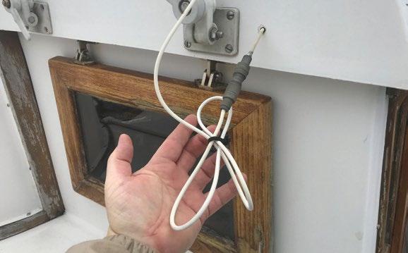
(Top) Ensure power and transmission cables for your VHF are properly supported and routed to prevent damage. (Middle) The Shakespeare ART-3 Antenna/Radio Tester is a simple way to check the overall health of your VHF system. (Bottom) Wire VHF antennas provide less windage (making them ideal for sailboat masts) but are “whippy” in longer lengths and not a good choice for deck-mount installations.
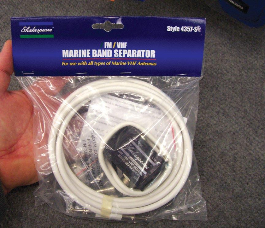
While a FM/ VHF marine band separator eliminates the need for separate FM and VHF antennas, the price is usually decreased VHF reception performance. If space exists, the best policy is to install two separate antennas.
CAPT. FRANK LANIER is an award-winning journalist, boat maintenance guru and owner of Capt F.K. Lanier & Associates, Marine Surveyors and Consultants: Whether you’re planning a new installation or looking to get the most from your existing one, there are a few ways to fine-tune your VHF radio system for optimal performance.
VHF (Very High Frequency) radios operate in the 30 to 300 MHz range, with marine VHF radios operating within the 156 to 174 MHz band. While VHF radio waves can be slightly curved by the atmosphere (adding to a radio’s range) wave propagation is primarily “line-of-sight,” meaning effective distance is limited by the antenna height of both the transmit and receive radio.
Antenna selection and installation One simple way to improve performance is to locate your antenna as high as possible, such as atop your radar arch, hardtop or T-top. While mast installations are a great height option for sailboats, signal loss can be an issue for longer antenna coax cable runs. As soon as the transmission signal leaves your radio and starts along the coax cable, it begins to lose strength. This loss, measured in decibels (dB), is a factor of coax cable length, quality of construction and the number of connectors or cable splices in the run, each of which increases signal loss and reduces radio performance.
When it comes to coax cable, bigger is better. Installation options range from RG-58 coax (the least expensive) to RG-8X and RG-213, the latter options being better quality coax that provides the least amount of signal loss. While signal loss for coax cable runs on smaller vessels (less than 20 feet) is not generally a huge concern, even in such a short run signal loss can be cut in half by using RG-8X instead of RG-58.
Antenna type and quality is another important part of the performance equation. Less expensive fiberglass antennas often utilize a thin copper wire for the “element” (the part that actually radiates and receives signals), compared with the more substantial brass or copper tubes found in premium antennas.
A crucial element of antenna selection is “gain,” the increase (or decrease) of an antenna’s effective radiated power. Gain essentially describes how an antenna maximizes and shapes or refocuses the signal it transmits, channeling more of it towards the horizon for example (where it does the most good) rather than skyward or into the water. VHF antenna gain is measured in dBs, with antennas typically falling within three common ratings: 3dB, 6dB and 9dB. Antennas with a higher dB rating provide a sharper, more concentrated radiation pattern (and greater theoretical distance) than those with lower dB ratings (think spotlight compared to a floodlight).
However, the best choice is not always simply to select the antenna with the highest dB. The best choice for a smaller powerboat is typically a 6dB antenna, which provides maximum range with minimal signal loss (due to rolling while underway). Larger power vessels with dual VHF radios may opt for the belt and suspenders approach by installing a 9dB antenna at the upper helm (which will typically be used in calmer seas) and a 6dB or 3dB antenna at the lower helm for use in rougher conditions.
Radio selection: Power and performance As all fixed-mount VHF marine radios are limited by law to 25 watts of transmit power, the only time output power becomes a factor performance-wise is when a full 25 watts is not achieved.
One cause of reduced transmit power is low battery voltage. Optimum battery voltage for a typical 12 VDC system (with the engine running and alternator operating properly) is around 13.6 volts. This drops to 12.6 volts with the engine off and battery fully charged. If battery voltage is less (say 11.6 or below) then radio transmit power will be significantly reduced.
A portable voltmeter is an invaluable tool when testing batteries for proper output. When measuring battery voltage, be sure to check voltage levels with the radio both keyed and unkeyed. A bad battery may show an acceptable voltage level with the radio simply turned on, but that voltage can drop dramatically once the radio is keyed and the battery is placed under load.
Test devices such as the Shakespeare ART-3 Antenna/Radio Tester are a handy way to test the overall health of your VHF system. The ART-3 tests receiver function, as well as radio output power and Voltage Standing Wave Ratio (VSWR), an indication of antenna system efficiency. If permanently mounted, the ART-3 can be connected to the vessel’s 12 VDC system, allowing you to check battery voltage at the flip of a switch. ★


