
9 minute read
ASSEMBLE PISTONS

from Caterpillar Cat 973 TRACK LOADER (Prefix 91L) Service Repair Manual (91L00001 and up)
by komdsyauhndk

1. Install the connecting rod (4) in the piston with the bearing tab groove (slot) (1) on the same side as the cutout (depression) (3) on the head of the piston.
2. Install piston pin (2) and retaining rings (5) in piston.
Advertisement
3. When old pistons are to be used, clean the piston grooves with an acceptable piston groove cleaning tool.
4. Install the spring for the oil ring. Install the oil ring with tool (A). The gap in the ring must be approximately 180° from the oil ring spring connections.
5. The two compression rings have marks "UP-1" and "UP-2." The rings must be installed with these marks toward the top of the piston with "UP-1" as the top ring. After installation of all three piston rings, put piston rings in position so gaps in rings are 120° apart.
NOTE: Compression rings that do not have identification can be installed either way.
6. To check the clearance between the piston ring grooves and rings, see Specifications.
7. See SPECIFICATIONS to check the clearance between the ends of the piston rings (end gap).
End By: a) install pistons
Previous Screen
Product: TRACK LOADER
Model: 973 TRACK LOADER 91L
Configuration: 973 TRACK TYPE LOADER 91L00001-UP (MACHINE) POWERED BY 3306 ENGINE
Disassembly and Assembly
973 TRACK-TYPE LOADERS
Media Number -SENR2458-01
Cylinder Liners
SMCS - 1216-11; 1216-12
Remove Cylinder Liners
Start By: a) remove pistons
1. Remove the coolant from the cylinder block.
2. Put covers on journals of crankshaft for protection from dirt or water.
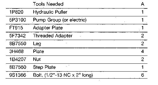
3. Remove cylinder liners (1) with tooling (A).
Install Cylinder Liners
1. Clean the cylinder liners (3) and the liner bores in the cylinder block.
2. Install the cylinder liners in the block without the O-ring seals or filler bands.
3. Check the cylinder liner projection as follows: a) Install the S1589 Bolts (2) and 1S379 Washers of tooling (B) on the cylinder block next to each liner. Tighten the bolts evenly, in four steps: 14 N·m (10 lb ft), 35 N·m (25 lb ft), 70 N·m (50 lb ft), and 95 N·m (70 lb ft). b) Put adapter plate on top of the liner and install the remainder of tooling (B). Tighten the 1D4595 Bolts (1) evenly in four steps: 7 N·m (5 lb ft), 20 N·m (15 lb ft), 35 N·m (25 lb ft), and 70 N·m (50 lb ft). c) Check to be sure the distance from the bottom edge of the crossbar to the top of the cylinder block is the same on both sides of the liner. d) Check the cylinder liner projection with tool group (C) at four locations around the liner. e) Liner projection must be 0.033 to 0.175 mm (.0012 to .0069 in) (make the measurement to the top of the liner flange, not the inner ring). The maximum differential between high and low measurements made at four places around each liner is 0.05 mm (.002 in). The average projection of liners next to each other must not be more than 0.05 mm (.002 in). The maximum difference in the average projection of all cylinder liners under each cylinder head must not be more than 0.10 mm (.004 in).

NOTE: If the liner is turned in the bore, it can make a difference in the liner projection.
4. If the liner projection is not 0.033 to 0.175 mm (.0012 to .0069 in), check the thickness of the following parts: spacer plate, spacer plate gasket and cylinder liner flange. The thickness of the spacer plate must be 9.970 ± 0.025 mm (.3925 ± .0010 in). The thickness of the spacer plate gasket must be 0.208 ± 0.025 mm (.0082 ± .0010 in). The thickness of the cylinder liner flange must be 10.282 ± 0.020 mm (.4048 ± .0008 in).
NOTE: If the liner projection changes from point to point around the liner, turn the liner to a new position in the bore. If the liner projection is still not to specifications, move the liner to a different bore.
5. When the cylinder projection is correct, put a mark on the liner and block so the liner can be installed in the same position from which it was removed.
NOTE: Cylinder liner projection can be adjusted by the removal of material from (machining) the contact face of the cylinder block with the use of the 8S3140 Cylinder Block Counterboring Tool Arrangement. Machine to a minimum depth of 0.76 mm (.030 in) and to a maximum depth of 1.14 mm (.045 in). The instructions for the use of the tool group are in Special Instruction, Form No. FM055228. Shims are available for the adjustment of the liner projection. See CYLINDER LINER PROJECTION in TESTING AND ADJUSTING for the shim thickness and part number.
6. Remove tooling (B) and (C). Remove the liner.
7. Put liquid soap on bottom liner bore in block, on grooves in lower liner and on O-ring seals (4). Install O-ring seals on the liner.
8. Put filler band (5) in clean SAE 30 oil for a moment and install on the liner. Install cylinder liner immediately in the cylinder block (before expansion of filler band).
9. Make sure the mark on liner is in alignment with the mark on the block. Use tooling (A) to push the liner into position.
10. Do Steps 5 through 9 for the remainder of the cylinder liners.
End By: a) install pistons
Previous Screen
Product: TRACK LOADER
Model: 973 TRACK LOADER 91L
Configuration: 973 TRACK TYPE LOADER 91L00001-UP (MACHINE) POWERED BY 3306 ENGINE
Disassembly and Assembly
973 TRACK-TYPE LOADERS
Media Number -SENR2458-01
Connecting Rod Bearings
SMCS - 1219-10
Remove And Install Connecting Rod Bearings
Start By: a) remove oil pump b) remove oil pan plate
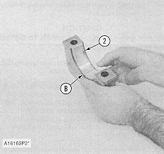
1. Turn the crankshaft until two pistons are at the bottom center. Remove connecting rod caps (1) from the two connecting rods. Remove the lower half of the rod bearing from the rod bearing cap.
2. Push the connecting rods away from the crankshaft. Remove the upper half of the rod bearing from the connecting rod.
NOTE: Install the connecting rod bearings dry when the clearance checks are made. Put clean engine oil on the connecting rod bearings for final assembly.
3. Install the upper half of the rod bearing in the connecting rod.
4. Install the lower half of the rod bearing in the connecting rod cap.
NOTE: Be sure the tabs in the back of the connecting rod bearings are in the tab grooves of the connecting rod and cap.
5. Use Plastigage (A) to check the connecting rod bearing clearance.
6. Put Plastigage (A) on the connecting rod bearing.
7. Put clean engine oil on the threads of the rod bolts and seat surfaces of the nuts.
CAUTION
When connecting rod caps are installed, make sure the number on the side of the cap is next to and respective with the number on the side of the connecting rod.
NOTE: Do not turn the crankshaft when Plastigage (A) is in position.
CAUTION
Do not use an impact wrench to tighten the nuts an additional 90°.
8. Install connecting rod cap (1). Install the nuts. Tighten the nuts to a torque of 40 ± 4 N·m (30 ± 3 lb ft). Put a mark on each nut and the end of each bolt. Tighten the nuts 90° more. Remove the connecting rod caps. Remove Plastigage (A) and measure the width of the Plastigage. The connecting rod clearance must be 0.076 to 0.168 mm (.0030 to .0066 in) for new bearings. The maximum clearance with used bearings is 0.25 mm (.010 in).
9. Install the connecting rod caps and tighten the nuts as in Step 8.
10. Do Steps 1 through 9 for the remainder of the connecting rod bearings.

End By: a) install oil pan plate b) install oil pump
Copyright 1993 - 2021 Caterpillar Inc.
Previous Screen
Product: TRACK LOADER
Model: 973 TRACK LOADER 91L
Configuration: 973 TRACK TYPE LOADER 91L00001-UP (MACHINE) POWERED BY 3306 ENGINE
Disassembly and Assembly
973 TRACK-TYPE LOADERS
Media Number -SENR2458-01
Crankshaft Main Bearings
SMCS - 1219-10
Remove And Install Crankshaft Main Bearings
Start By: a) remove oil pump b) remove oil pan plate
1. Remove the No. 1, 3, 5 and 7 main bearing caps (1). Remove the crankshaft thrust bearing from the No. 7 main bearing.
2. Remove the lower half of the main bearing from the main bearing caps.
Caution
If the crankshaft is turned in the wrong direction, the tab on the bearing will be pushed between the crankshaft and bearing area in block which can cause damage to the block or crankshaft.
3. Install tool (A) in oil hole in the crankshaft journal and remove the upper half of the main bearing as the crankshaft is turned and the main bearing is moved out of the cylinder block.
NOTE: Install the main bearings dry when the clearance checks are made. Put clean engine oil on the main bearings for final assembly.
Caution
Make sure the upper and lower halves of the main bearings are installed so the bearing tabs fit into the notch in cylinder block and the main bearing caps.
4. Install new lower half of main bearings (2) in the main bearing caps. Use tool (A) and install the upper half of the main bearings in the cylinder block.
5. Put clean oil on the thrust bearing and install a new thrust bearing with the identification "BLOCK SIDE" toward the cylinder block and the tabs on the thrust bearings in the machined area in the cylinder block.
NOTE: When the bearing clearance is checked and the engine is in a vertical position, such as in the vehicle, the crankshaft will have to be lifted up and held against the upper halves of the main bearings to get a correct measurement with the Plastigage. The Plastigage will not hold the weight of the crankshaft and give a correct indication. If the engine is in a horizontal position, it is not necessary to hold the crankshaft up. Do not turn the crankshaft when the Plastigage is in position to check clearances.
6. Check the main bearing clearances with Plastigage (B) as follows: a. Put a piece of Plastigage (B) on the surface of the lower half of the main bearing.
Caution
Make sure the part number on the main bearing cap is toward the front of the engine and the number on the main bearing cap is the same as the number on the cylinder block on the left side of each main bearing cap.
NOTE: Do not turn the crankshaft when Plastigage (B) is in position.
b) Install main bearing caps (1) for No. 1, 3, 5 and 7 main bearings. Put clean engine oil on the bolt threads and the face of the washers and install the bolts. Tighten the bolts to a torque of 40 ± 4 N·m (30 ± 3 lb ft).
Caution
Do not use an impact wrench to tighten the bolts an additional 90° more.
c) Put a mark on each bolt and main bearing cap, then tighten the bolts 90° more.
d) Remove the main bearing caps for No. 1, 3, 5 and 7 main bearings. Remove Plastigage (B) and measure the width of the Plastigage. The main bearing clearance must be 0.076 to 0.165 mm (.0030 to .0065 in). Maximum permissible clearance with used bearings is 0.25 mm (.010 in).
7. Install main bearing caps (1) and tighten the bolts as in Step 6b and 6c.
8. Remove No. 2, 4 and 6 main bearing caps. Do Steps 2, 3, 4, 6 and 7 for the No. 2, 4 and 6 main bearings.
9. Check the crankshaft end play with tooling (C). The end play is controlled by the thrust bearings on the No. 7 main bearing. End play with new bearings is 0.064 to 0.386 mm (.0025 to .0145 in). The maximum permissible end play with used bearings is 0.64 mm (.025 in).
End By: a) install oil pan plate b) install oil pump

Previous Screen
Product: TRACK LOADER
Model: 973 TRACK LOADER 91L
Configuration: 973 TRACK TYPE LOADER 91L00001-UP (MACHINE) POWERED BY 3306 ENGINE
Disassembly and Assembly
973 TRACK-TYPE LOADERS Media Number -SENR2458-01
Vibration Damper And Pulley
SMCS - 1153-11; 1153-12; 1205-11; 1205-12
Remove Vibration Damper And Pulley
Start By: a) remove radiator and guard
1. Fasten a strap and hoist to fan (1) and remove the fan from the fan drive. The weight is approximately 39 kg (85 lb).
2. Remove bolts (3), the ring and damper assembly (4) from the pulley.
3. Remove V-belts (2).
4. Use two 1/2" -13 NC bolts 1 3/4 inches long to fasten bar (5) to the pulley so it can not turn while bolt (6) is loosened. Bar (5) is 9.5 mm x 19.0 mm x 762 mm (.375 inches x .75 inches x .30 inches). Remove bolt (6) and the washer from the crankshaft. Install a 3.2 mm (.125 in) thick spacer on bolt (6) and install bolt (6) back in the crankshaft. The spacer will give clearance between the washer and bolt (6) on the pulley.
NOTE: With the use of the spacer, the force during the removal of the pulley will be on the end of the crankshaft rather than on the bolt threads.
Caution
If the spacer is not used the bolt threads can be damaged.
5. Install tooling (A) and loosen the pulley from the crankshaft.
6. Remove tooling (A). Remove the bolt, washer, spacer and pulley from the crankshaft.
