PERFORMANCE — Constant pursuit of efficiency and productivity with more power, more speed.
DESIGN — Operator-centric with an uncompromising stance on ease-of-use and comfort.
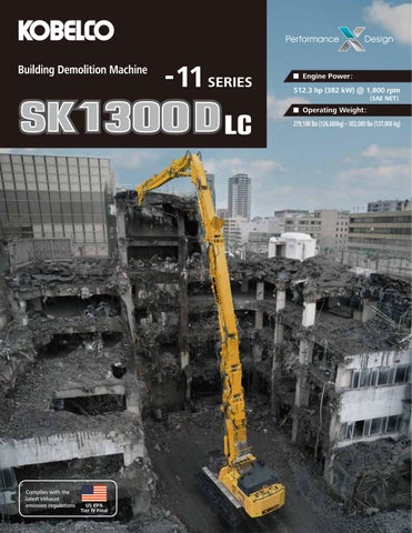
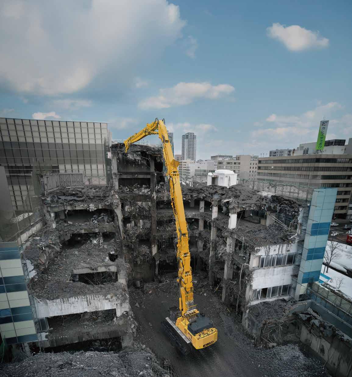
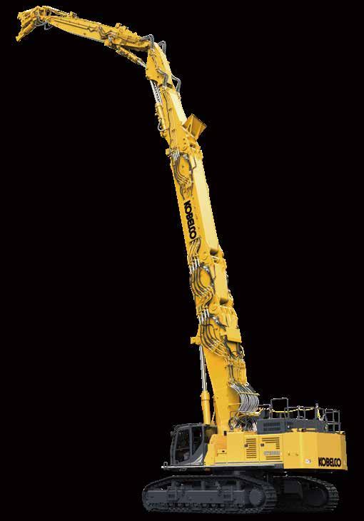
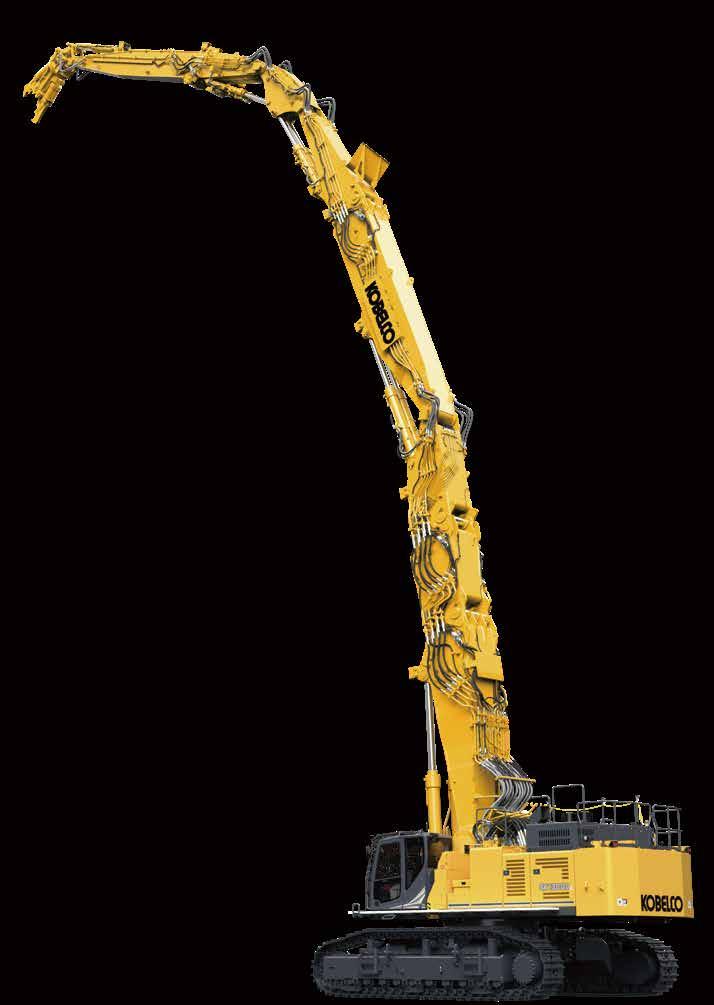
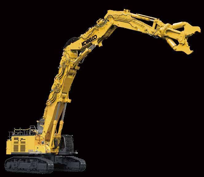
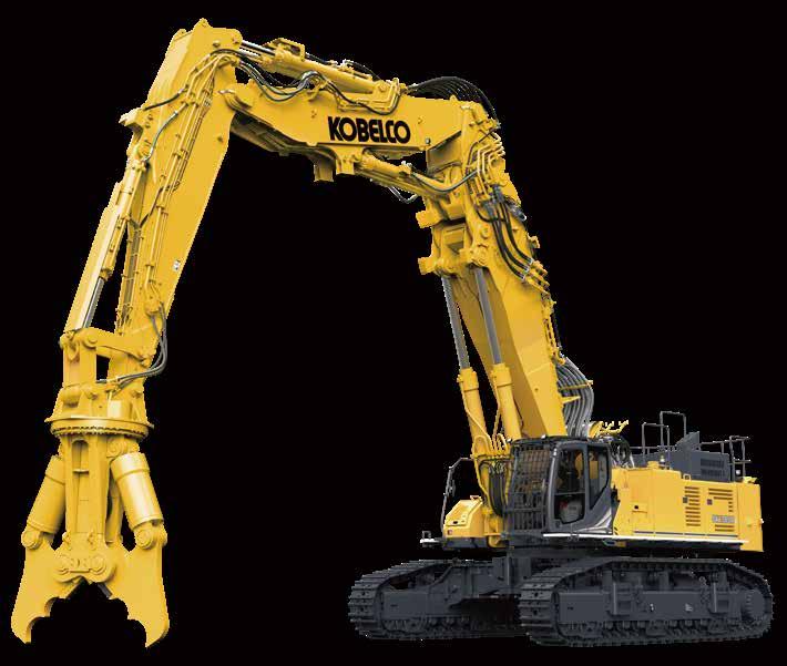
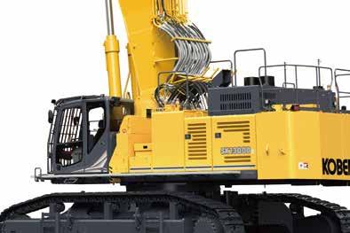
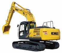
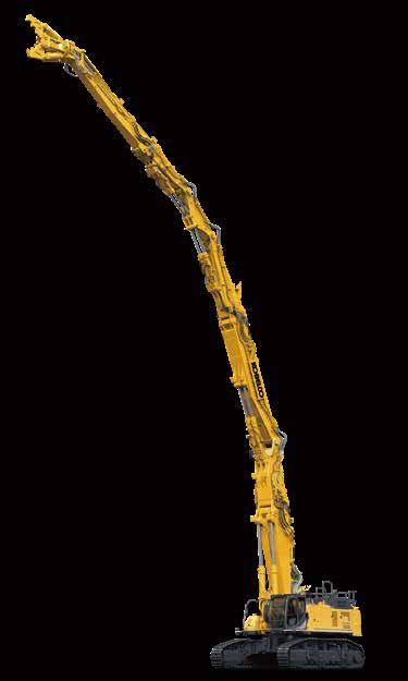
The SK1300DLC is a new super-large building demolition machine that further enhances these combined values.
With six specifications, including a 4-piece high reach demolition attachment spec with a working height of 40 m, and a separate boom spec that covers powerful lifting and underground digging with a large front attachment, you can select the specification that best suits your work.
With its wide range of specifications and optimal performance, the SK1300DLC offers users greater value than ever before by turning increasingly stringent transport regulations into an advantage thanks to its easy disassembly for transport and shared attachments, which reduce initial costs.
KOBELCO continues to strive to create products that are unique and unparalleled.
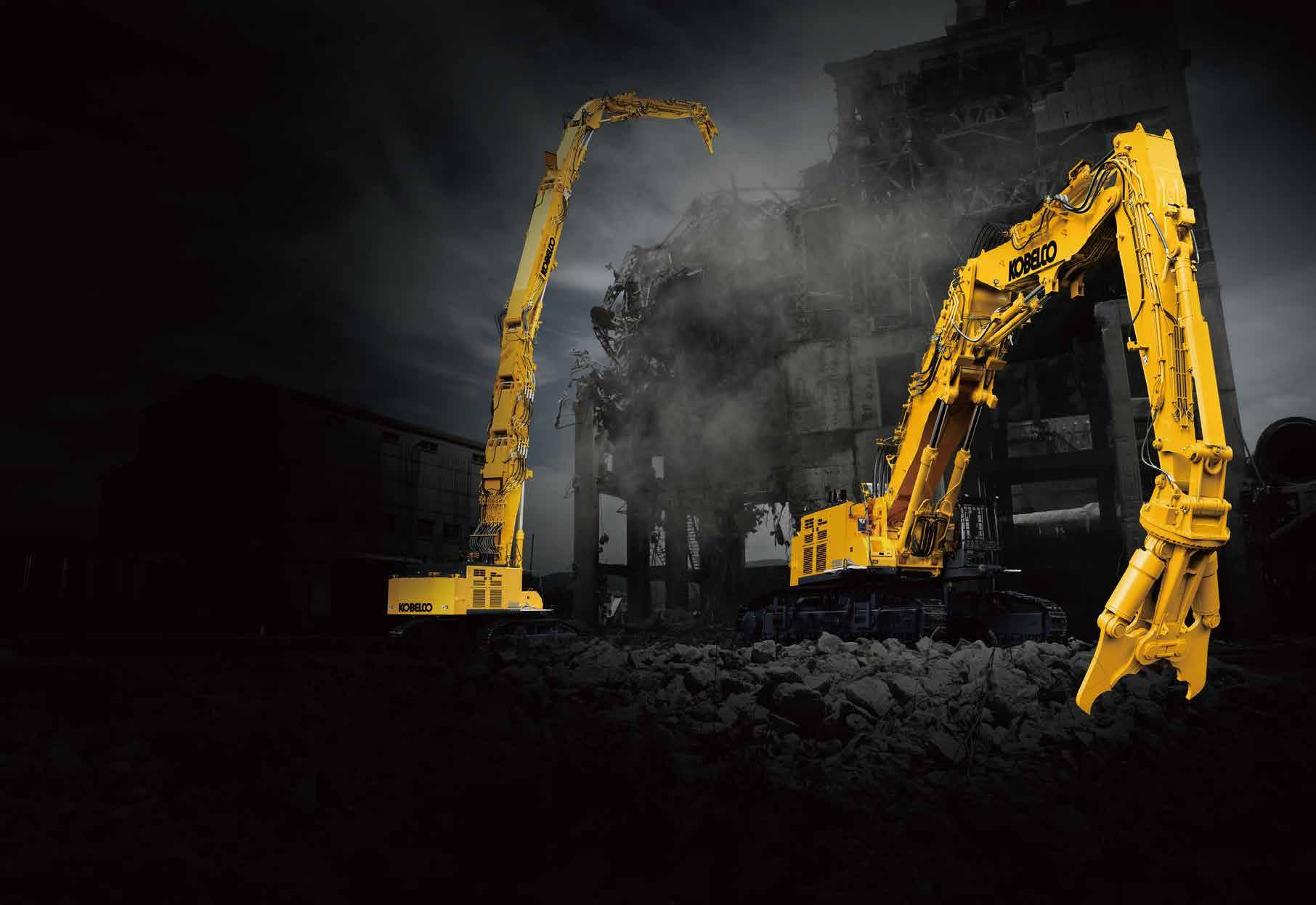
Ultra-high reach, with multiple boom and arm configurations providing flexibility.
3-piece
Redefining High-Reach Demolition. Height Expands Your Options
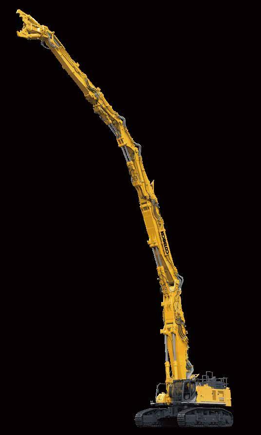
4-piece Ultra long attachment specification
Equipped with NEXT ADVANCE, a flexible configuration ultra-high reach demolition attachment solution.
The new NEXT ADVANCE high reach demolition attachment was developed to achieve greater working heights, with improved tool capacities. The unique new articulated structure of the 4-piece ultra long attachment make it possible to greatly overcome current operational limits of other 100 ton-class machines.
Exclusive articulated insert boom
One example of the new NEXT ADVANCE technology is the introduction of articulation joints to the insert boom. By keeping the center of gravity of the overall machine lower, even larger crushers can be used without the need to increase overall base machine weight.
Choose from 40 m and 35 m height configurations
Adding a 4-piece attachment configuration to the 130 t class has allowed a max height of 40 m previously limited only to larger machines. Choose the 35 m boom configuration to support even larger crushers.
Working range
Max. working height:
40 m type : 129’10” {39.6 m}
35 m type : 115’5” {35.2 m}
Max. permissible working reach (Along):
40 m type :
62’0” {18.9 m}
35 m type : 53’10” {16.4 m}
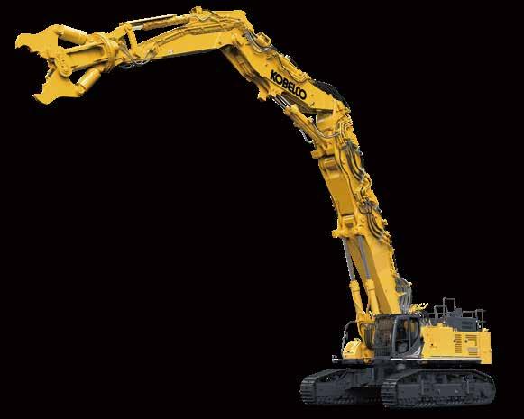
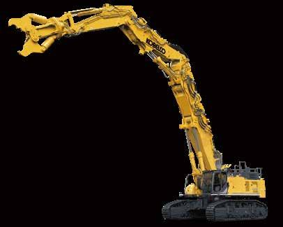
3-piece ultra long attachment specification
Large working radius utilizes machine's full reach capability
The 3-Piece configuration is designed for optimal balance between working height and working reach. With this balanced set-up, the customer can cover a broad range of demolition scenarios.
Choose from 35 m and 31 m height configurations
The 3-piece attachment configuration offers two options, 35 m height and 31m height. These have working reach of 21 m and 19m respectively, which are greater than the 4-piece specification.
Max. tool weight:
35 m type :
11,100 lbs {5,050 kg}
31 m type :
13,400 lbs {6,100 kg}
Working range
Max. working height:
35 m type :
115’1” {35.1 m}
31 m type :
100’9” {30.7 m}
Max. permissible working reach (Along):
35 m type :
70’3” {21.4 m}
31 m type :
61’8” {18.8 m}
Smarter Choices for Low-Level and Foundation Work
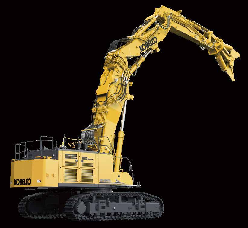
Separate boom specification
Wide working range envelope with powerful lift capacity
The separate boom specification allows for a wide range of applications, from low-level building demolition to foundation demolition. There are two settings: Normal mode and Foundation mode. Normal mode provides a good balance between maximum tool weight and working range, making it suitable for various demolition situations.
In foundation mode, a larger crusher can be attached, allowing for powerful and efficient work especially in foundation demolition. The two modes can be easily switched on the monitor.
Separate boom specification with insert
To reach higher place
The separate boom specification can be equipped with an insert boom, which allows the working height to be extended up to 24m above ground. The maximum tool weight remains the same at 9.6t as in the normal mode without inserts, so the same crusher as without inserts can be used.
Max. tool weight: 77
21,100 lbs
Max. workingheight:
Insert boom (short type) [N2-B]
The Insert boom (N2-B) is a part that extends the length of the main boom. It is a highly versatile part that can also be used on both the 3-piece and 4-piece ultra long attachment.
Working Ranges Comparison Chart (Arm Top Pin Position)
*If with insert boom, it can’t be used for foundation work.
Assembly, Disassembly, and Transportability
A New Dimension in Streamlining and Speeding Up Jobsite Preparation
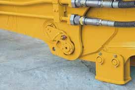
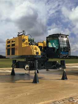
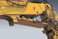
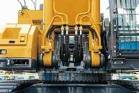
Subframe structure enables 32 t transportation
The main boom attachment point uses a unique modular subframe structure with a simple alignment mechanism that allows easy removal and installation of the main boom structure when required. The guide structure and the hydraulic pin make it easy to remove and install the main boom, achieving a base machine transportation mass of 32 tonnes or less, simplifying transport in urban environments.
Main boom disassembly time: Approx. 2 hours
Transportation mass of base machine: Approx. 32 t (Height: Approx. 4.1m <including trailer bed>, Width: Approx. 3.2m)
Transportation width:
Approx. 10’6” {3.19 m}
13’5” {4.10 m} Transportation height:
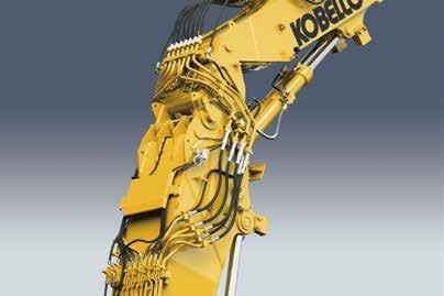
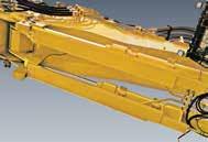
New arm connection design reduces assembly time
A newly developed split arm design simplifies installation of arm segments. A hook structure with separate opposing pins and a guide are used in conjunction with a hydraulic pin connection to reduce the time required for assembly and disassembly.
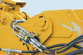
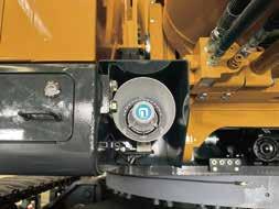
Safe and quick hydraulic connection
Hydraulic pipes are installed on the left and right sides of the attachment for improved reliability and ease of assembly. During assembly and disassembly, hydraulic connectors can be safely coupled without the need to climb on top of the attachment. A single action multi-line coupler system has been implemented for the connection of small diameter pipes, reducing setup time.
Left/right separate opposing pins Connection hook
Hydraulic pin / Remote control
Two piece counterweight with steps
A two-piece counterweight design improves ease of transport. Both counterweights are encased in a single frame; the lower counterweight incorporates a stepped design to improve accessibility for assembly and disassembly.
Upper weight:
Approx.
17,200 lbs {7,800 kg}
Lower weight:
Approx.
31,100 lbs {14,100 kg}
A translifter for quickly and safely assembling/ disassembling the lower car body of the base machine and the crawler frame is equipped as standard. The translifter includes synchronized four-leg control, making Translifter with synchronised four-leg control
A New Dimension in Design and Functionality
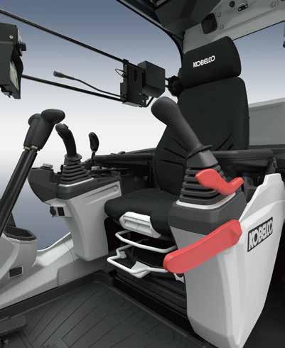
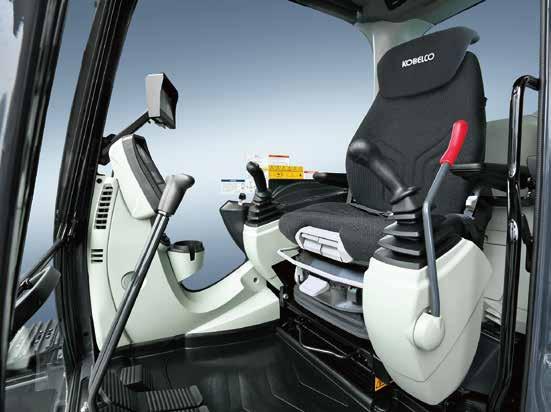
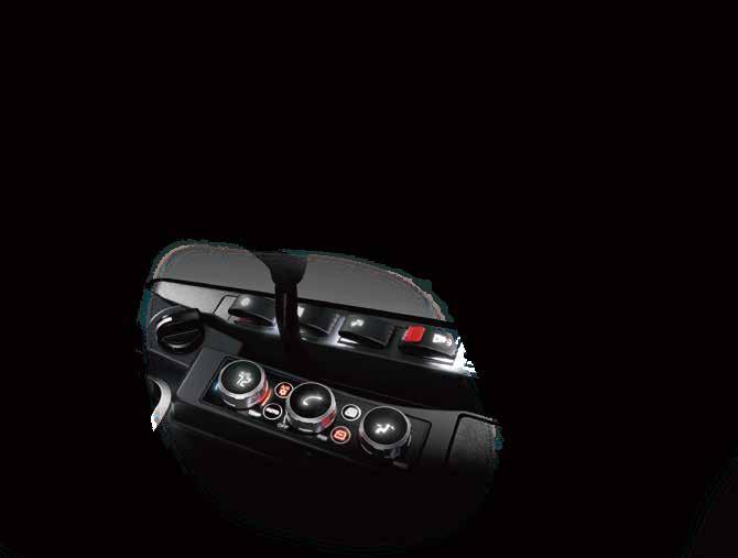
Operator station designed for all-day comfort and reduced fatigue
The spacious operator station minimizes operator fatigue with its modern design and comfort inclusions.
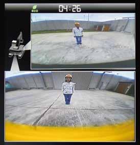
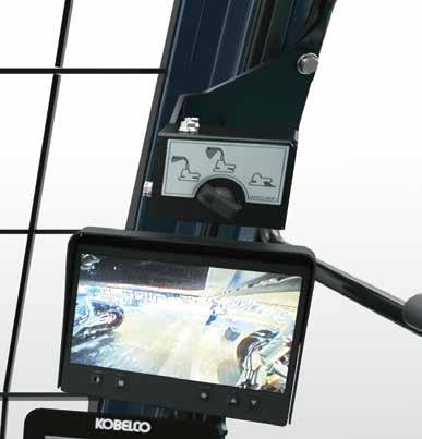
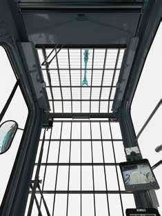
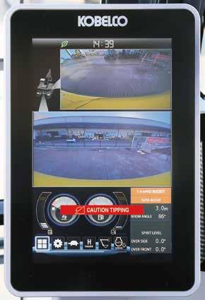
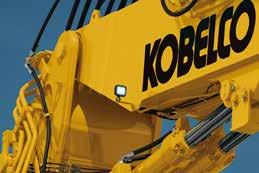
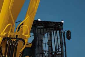
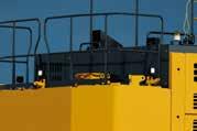
Monitoring cameras eliminate blind spots from the operator's seat
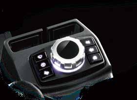
In addition to being able to see areas around the machine not visible to the naked eye, the operator can also quickly check dem front attachment from the operator’s seat. Cameras are installed at four locations on the machine body (rear, right side, left frame), and one switchable camera is installed on the arm of the high reach demolition attachment/equipment spec machine. In ad monitor, an additional monitor can be added to display feeds from four cameras simultaneously. The operator can easily switch
the added monitor using the rotary switch.
Rear,right, left side images / three side view
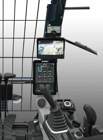
Information is consolidated in front of the operator. The monitor also remains within the sightline.
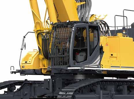
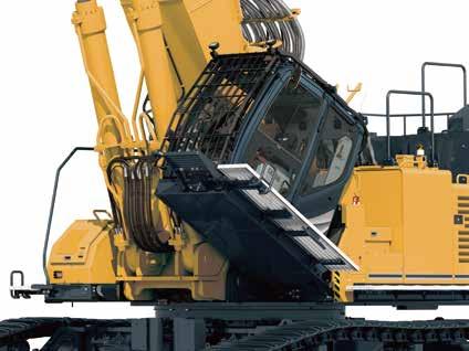
Demolition spec cab with tilting function
A Demolition spec cab with a 30° tilt capability is equipped as standard for comfortably demolishing tall buildings where the operator spends a long time looking up. With no beam between the front window and skylight to block visibility and angled grids on the cab guard, good work visibility is maintained.
Excellent visibility (Front and Skylight)
Kobelco’s Advanced Technologies for Maximum Uptime and Operator Safety
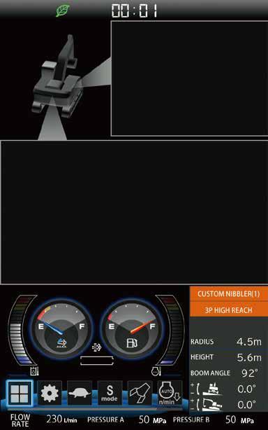
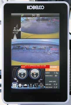
Dedicated building demolition machine display
Stability warning system with longitudinal/horizontal detection
The device calculates the tipping danger area from the posture of the attachment and swing angle of upper structure, and if it detects a dangerous situation, it alerts the operator with an alarm and a warning on the screen. System distinguishes between the front and sides by detecting the position relative to the upper structure and crawler. As the system recognizes that the safe working range differs between the front and sides, the upper structure can swing within a wider restricted range for each.
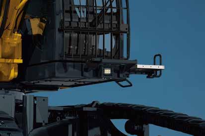
LED work light to keep visibility in low light or at night
Equipped with nine high brightness LED work lights. The lights keep the work area bright
Cab interference prevention system with soft-stop feature
If the attachment comes within a certain distance of the cab, an alarm and warning on the screen alert the operator, and the attachment stops softly and automatically to protect the operator. Since there is no worry of contact, the operator can confidently perform lever operation even close to the cab.
Jib cylinder guard (Optional)
Jib cylinder guarding is installed to prevent damage during demolition operations.
Boom cylinder guard (Optional)
Boom cylinder guarding is installed to prevent damage during demolition operations.
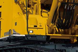
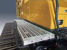
A walkway is provided, allowing easy access to inspection and maintenance
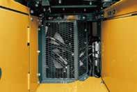
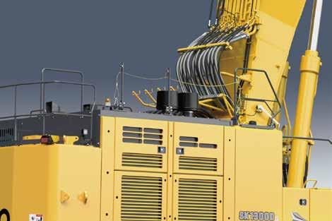
Reversible cooling fan
Reliability is improved with the reversing fan, which reduces build-up of debris on the cooling package.
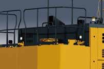
Newly designed handrails improve safety when working on top of the bonnet.
Walkways are provided on both the left
filter is equipped for improved filtration
Allows storing of remote controllers, etc.
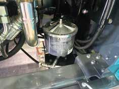
Electric lubrication system
Greasing of each pin in the attachment’s moving parts can be performed quickly and with minimal effort.
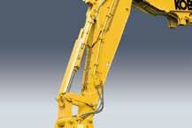
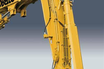
Safety valve
Boom, arm and jib cylinders are equipped with safety valves for increased safety.
Maintains safety by alerting workers in the area with clear audio quality.
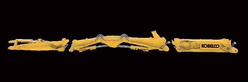
New attachments designed for standardization across multiple configurations
Attachments are designed for common use across multiple boom and arm combinations. Attachment configurations can be quickly and easily changed to suit the job requirements, increasing machine utilization.
1 x 13.0 U.S.gpm {49.3 L/min}, 1 x 7.9 U.S.gpm {30.1 L/min}
4,790 psi {33.0 MPa}
4,930 psi {34.0 MPa}
4,790 psi {33.0 MPa}
3,760 psi {25.9 MPa}
725 psi {5.0 MPa}
3,630 psi {25.0 MPa} / 4,790 psi {33.0 MPa}
(Factory setting / Max. setting)
2,990 psi {20.6 MPa}
Gear type
5+5+1 Spool valve × 1pc -spool
Air cooled type
Two fixed capacity axial piston motor
Hydraulic; locking automatically when the swing control lever is in the neutral position
Wet multiple plate
3.3 rpm (Ultra long attachment)
6.0 rpm (Separate boom)
70,800 lb-ft {315 kN·m}
15’10” ft-in {4,820 mm}
Operating weight & ground pressure
2 × axial-piston, two-speed motors
Hydraulic brake per motor
Oil disc brake per motor
55 each side
2.6 / 1.6 mph {4.2 /
All-weather, sound-suppressed steel cab mounted on the high suspension mounts filled with silicone oil and equipped with a heavy, insulated floor mat.
Two hand levers and two foot pedals for travel
Three hand levers and one foot pedal for front attachment and swing
Electric rotary-type engine throttle
capacities & lubrications
Fuel tank
Cooling system
Engine oil
Travel reduction gear
Swing reduction gear
Hydraulic oil tank
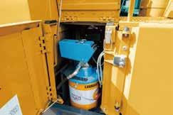
DEF/Urea tank
Cylinders
U.S.gal {57.0 L}
x 11.6 U.S.gal
U.S.gal {599 L} tank oil level
U.S.gal {1,070 L} hydraulic system
U.S.gal {83.0 L}
Boom cylinders [N1]
Jib cylinders [N5+N6+N7]
Arm cylinders [N5+N6+N7]
Bucket cylinder [N8-B / N8-A]
Attachment type
Boom cylinders [N1]
Jib cylinders
Arm cylinders
Bucket cylinder
Specifications
Dimensions (base machine + main boom)
Assembled machine dimensions
4-piece ultra long attachment specification
figure
3-piece ultra long attachment specification
Separate boom specification with insert
Separate boom specification
Dimensions and mass when disassembled
Base machine
Ultra long attachment
Separate attachment
Front arm (standard type) [N8-A]
Crawler
Crawler (25.6 {650
/ one side)
Specifications
Working Ranges
* Although within Max. tool weight, the center of gravity of different tool types can vary. Depending on the tool type and working position of the front attachment, the cylinder may not hold the excessive load making it difficult to perform the intended work.
4-piece ultra long attachment specification
3-piece ultra long attachment specification
Separate boom specification with insert
Separate boom specification
the region where, depending on the posture, the cylinder cannot be held.
Lift capacities
Rating over front Rating over side or 360 degrees
Boom: Separate Arm: 43 10 {13.36 m} Without bucket: Counterweight: 48,281 lbs {21,900 kg} Shoe: 25.6” {650 mm} (Heavy Lift)
1. Do not attempt to lift or hold any load that is greater than these lift capacities at their specified lift point radius and heights. Weight of all accessories must be deducted from the above lift capacities.
2. Lift capacities are based on machine standing on level, firm, and uniform ground. User must make allowance for job conditions such as soft or uneven ground, out of level conditions, side loads, sudden stopping of loads, hazardous conditions, experience of personnel, etc.
3. Arm top defined as lift point.
4. The above lift capacities are in compliance with ISO 10567. They do not exceed 87% of hydraulic lift capacity or 75% of tipping load. Lift capacities marked with an asterisk (*) are limited by hydraulic capacity rather than tipping load.
5. Operator should be fully acquainted with the Operator’s and Maintenance Instructions before operating this machine. Rules for safe operation of equipment should be adhered to at all times.
6. Lift capacities apply to only machine as originally manufactured and normally equipped by KOBELCO CONSTRUCTION MACHINERY CO., LTD.
7. Use this machine in the following applications. In specification for ultra long attachment type, demolition work. In specification for separate boom type, demolition work & loading work. Never use the machine for any purpose other than the above applications.
8. Please read carefully the manual before using machine.
Standard and optional equipment
ENGINE
HYDRAULIC SYSTEM
PIPING
CABIN
LIGHTS
WORKING EQUIPMENT
COUNTERWEIGHT
UNDERCARRIAGE
SAFETY
OTHERS
Note:
ISUZU 6WG1 (Tier IV Final certified)
Exhaust DOC/SCR system
Alternator 24 V / 90 A
Starter motor 24 V / 7 kW
Batteries 2 x 12 V (205 Ah)
Reversible hydraulic drive cooling fan
Auto deceleration function
Auto idle stop (AIS)
3 work modes H, S, Eco
Power boost 4,930 psi {34.0 MPa}
Pressure release function
Auto warm up system
Proportional Hand Control (for Rotation & N&B piping)
Hydraulic oil VG32
Hydraulic oil VG46
Rotation & N&B piping
QH piping
Air suspension seat with heating
10-inch color monitor
LED door light
Air-conditioner
Radio (AM/FM, AUX, USB, Bluetooth® and hands-free telephone)
Top and front window wiper
12 V power outlet
Sun screen
Back rest
LED work lights ; 2 on cab top, 1 on cab bottom, 1 on upper structure
LED work lights ; 3 on counterweight
LED work lights ; 2 on boom
LED work lights ; 2 on arm
Dual system water spray (only piping)
Layered C/W 48,300 lbs {21,900 kg} with swing flashers
Hydraulic pin joint type undercarriage and translifter
3-side 270-degree camera system (Rear, Right, Left)
Additional monitor
Arm camera
Cab lower mirror & right side mirror
Falling object deflector
Travel alarm
Cab interference prevention system
Stability warning system
Walkway (Left & Right side)
Handrail + stanchion + wire rope
Public address system
Emergency escape hammer
Electric pump for lubrication
Harness for engine room light
NEXT pin removal equipment
Cylinder guard (bucket)
Cylinder guard (main boom)
Cylinder guard (jib)
Bracket for machine lifting
Cat walk
3-year/3,000 hour warranty
KOMEXS machine monitoring
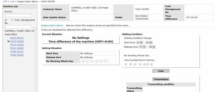
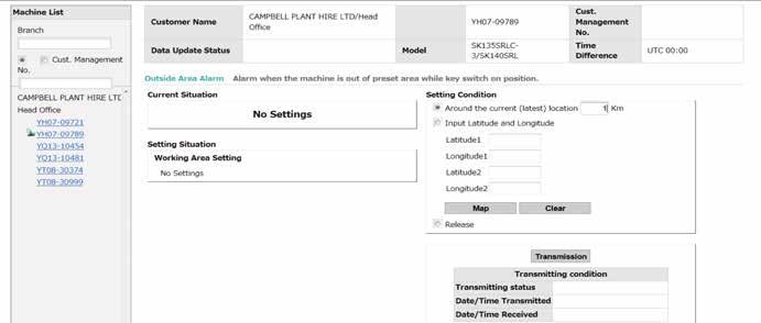
Direct Access to Operational Status
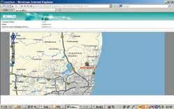
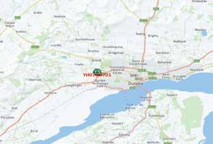
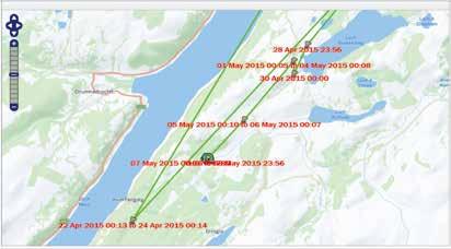
Location Data
•Accurate location data can be obtained even from sites where communications are difficult.
Remote Monitoring for Peace of Mind
KOMEXS (Kobelco Monitoring Excavator System) uses satellite communication and internet to relay data, and therefore can be deployed in areas where other forms of communication are difficult. When a hydraulic excavator is fitted with this system, data on the machine’s operation, such as operating hours, location, fuel consumption, and maintenance status can be obtained remotely.
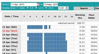
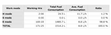
Operating Hours
•A comparison of operating times of machines at multiple locations shows which locations are busier and more profitable.
•Operating hours on site can be accurately recorded, for running time calculations needed for rental machines, etc.
Fuel Consumption Data
•Data on fuel consumption and idling times can be used to indicate improvements in fuel consumption.
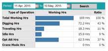
Graph of Work Content
•The graph shows how working hours are divided among different operating categories, including digging, travelling, and auxiliary tool operations.
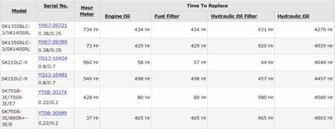
Maintenance Data and Warning Alerts
Machine Maintenance Data
•Provides maintenance status of separate machines operating at multiple sites.
•Maintenance data is also relayed to KOBELCO service personnel, for more efficient planning of periodic servicing.
Alarm Information Can Be Received through E-mail
Warning Alerts
•This system can provide an alert if an anomaly is sensed, preventing damage that could result in machine downtime.
•Alarm information or maintenance notice can be received through E-mail, using a computer or cell phone.
Daily/Monthly Reports
•Operational data downloaded onto a computer helps in formulating daily and monthly reports.
Alarm messages can be received on mobile device.
Bluetooth ® is a registered trademark of the Bluetooth SIG Inc. *GRAMMER is trademark of GRAMMER AG. registered in Germany and other countries.
Note: This catalog may contain attachments and optional equipment that are not available in your area. And it may contain photographs of machines with specifications that differ from those of machines sold in your areas. Please consult your nearest KOBELCO distributor for those items you require. Due to our policy of continuous product improvements all designs and specifications are subject to change without advance notice. Copyright by No part of this catalog may be reproduced in any manner without notice.