7 minute read
POWER TRAIN REPAIR

from John Deere XUV 825i Gator Utility Vehicle Service Repair Manual Instant Download (TM107119)
by kmd9iso9dkk
Clutch Removal and Installation
Required Tool:
Advertisement
•JDG61641 Clutch Removal Tool
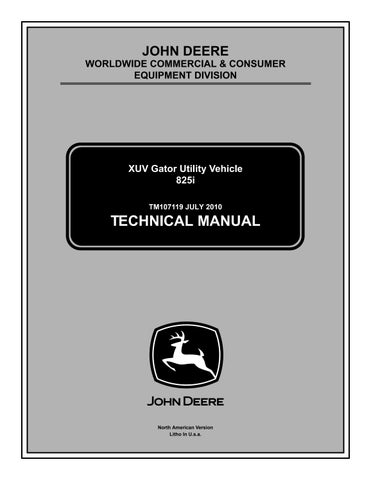
Clutch Housing Removal
1.Loosen hose clamp (A) and remove cooling air intake tube from clutch housing and frame bracket.
2.Remove air intake filter from tube. Clean filter to remove any dirt or debris. Set filter aside to dry.
3.Remove 11 M6 hex bolts (B) securing outer housing to inner housing. Remove outer housing.
Important: Avoid Damage! Place a small amount of grease on the contact tip of clutch removal tool JDG61641 before use. Failure to lubricate the clutch removal tool may result in damage to the engine output shaft or tool contact surface.
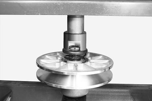
4.Insert a short wood block between drive belt (C) and secondary clutch (or use an impact wrench) to loosen secondary clutch M10 center bolt (D).
5.Slide driven clutch out from the transmission and roll the drive belt over the clutch and remove the belt.


6.Remove center bolt and washer securing secondary clutch to transmission input shaft.
7.Remove secondary clutch assembly.
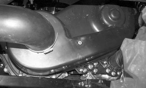
8.Remove M8 center bolt (E) and washer securing primary clutch to engine output shaft.
9.Install clutch removal tool JDG61641 (F) and separate primary clutch from engine crankshaft.
10.Remove primary clutch assembly.
11.Remove 3 M8x12 bolts (G) securing inner housing to transmission bracket.
12.Remove nine remaining M6x12 hex bolts (H) and bushings.
13.Remove inner housing.
Clutch Housing Installation
1.Install inner clutch housing over engine and transmission shafts. Loosely install 3 M8x12 bolts (A) to secure inner housing to transmission bracket.
2.Install nine M6 hex bolts (B) with bushings through housing seal to secure housing and tighten to specification.
3.Tighten 3 M8x12 bolts (A) securing housing to transmission bracket.
4.Ensure that engine crankshaft taper (C) and mating primary clutch socket are clean.

7.Install drive belt (F) to primary and secondary clutch sheaves.


5.Install primary clutch assembly to crankshaft taper, and secure with M8x150 hex bolt (D) and washer. Tighten bolt to specification.
6.Install secondary clutch to transmission input shaft, and secure with M10x80 hex bolt (E) and washer.
8.Insert a short wood block (G) between drive belt and secondary clutch, and tighten secondary clutch center bolt to specification.
9.Install outer clutch housing to inner housing, and secure with 11 M6 bolts (G).
10.I Install filter (H) to air intake tube. Press filter into tube until 3-5 mm of filter remains exposed.
11.Install cooling air intake tube through frame support and to clutch housing inlet. Tighten hose clamp (I) to secure intake to housing inlet.

Torque Specifications:
Clutch Housing Bolt. . . .. . . . . . . . . . . 11 Nïm (97 lb-in.)
Clutch Housing to Transmission Shoulder Bolt


. . 32 Nïm (24 lb-ft)
Drive Clutch to Crankshaft Bolt . . . . . 37 Nïm (26 lb-ft)
Driven Clutch to Transmission Bolt . . 73 Nïm (52 lb-ft)
Primary Drive Clutch Repair
Disassembly: cCaution: Avoid Injury! Components are installed under spring tension. Wear eye protection and use proper tools when installing and removing components with spring tension.
2.Remove cover and spring (B).
3.Check center shaft (C) for wear or damage.
4.Slide moveable sheave section (D) up and down center shaft to check for freedom of movement.
1.Evenly loosen six 1/4-20 x1 1/4 in. clutch cover bolts (A) in sequence.
5.Check contact surfaces of three flyweights (E) and rollers (F) for wear or damage.
6.Check flyweights for freedom of movement. Replace weights and pivot bolts (G) if weights are damaged or do not move smoothly.

7.Check belt contact surfaces (H) of sheaves for wear or damage.
8.Replace worn or damaged clutch or components.
Assembly: cCaution: Avoid Injury! Components are installed under spring tension. Wear eye protection and use proper tools when installing and removing components with spring tension.
Primary clutch assembly is the reverse of disassembly. Ensure that alignment marks “X” on the clutch cover and flyweight are aligned.
Torque Specifications:
Clutch Cover Bolt. . . . . . 12 - 13.5 Nïm (105 - 120 lb-in.)
Flyweight Pivot Bolt Nut. . . . 8 - 9.5 Nïm (72 - 84 lb-in.)
Driven Clutch Disassembly and Assembly
Disassembly: cCaution: Avoid Injury! Components are installed under spring tension. Wear eye protection and use proper tools when installing and removing components with spring tension.
1.Ensure that clutch center shaft (A) is clean.
2.Install spring (B) to seat in clutch spider.
3.Install clutch cover, aligning “X” match marks (C) on clutch cover and flyweight.


1.Compress clutch spring and collar, and remove snap ring (A). Remove collar and spring.
2.Inspect spring for damage. Replace if needed.
3.Separate moveable clutch section from stationary section.
4.Align cover with center shaft. Raise moveable sheave (D), and press down on cover to start an opposing pair of cover bolts.
5.Start remaining cover bolts. Tighten bolts evenly to prevent binding between cover and center shaft.
6.Tighten bolts to specification.
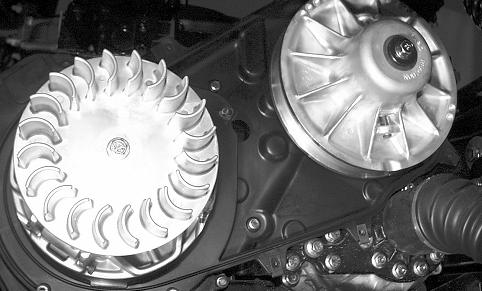
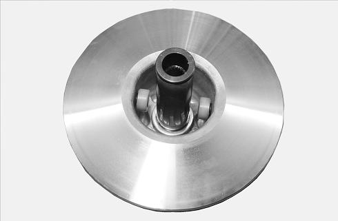
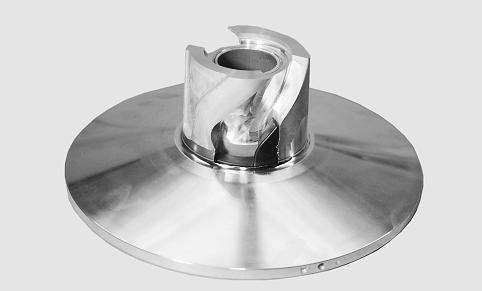
4.Inspect belt contact surface (B) of stationary sheave section. Ensure that surface is smooth.
5.Inspect condition of rollers (C). Ensure that rollers are not damaged and rotate freely.
6.Inspect condition of belt contact surface (D), ramps (E) and helical slots (F) in moveable sheave section. Ensure that all surfaces are smooth and free of damage.
Assembly: cCaution: Avoid Injury! Components are installed under spring tension. Wear eye protection and use proper tools when installing and removing components with spring tension.
Secondary clutch assembly is the reverse of disassembly. Ensure that alignment marks “X” are opposed when the moveable and stationary sheaves are assembled.

3.With moveable sheave fully inserted in fixed sheave, “X” alignment marks (C) should be opposed.
1.Ensure that spacer (A) is in place in well of stationary clutch section.
4.Install spring (D) and spring collar (E) to moveable sheave.
5.Compress spring, and install snap ring (F). Ensure that snap ring is fully installed to groove.
Transmission Removal
1.Park machine safely. See "Park Machine Safely" in the Safety section.
2.Block front wheels to prevent machine from rolling.

3.Remove cargo box from machine.
4.Jack up rear of machine and safely support machine on stands.
5.Remove rear wheels.
6.Drain oil from transmission.
2.Install movable sheave to fixed sheave by aligning helical slots to rollers (B).
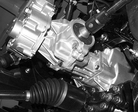
7.Remove the spring clip (A) and disconnect the shift rod from the transmission.
8.Disconnect transmission neutral switch (B) and remove harness restrainer (C) from bracket.
Note: Note or mark hole on differential lock shift lever that connections are made to.
9.Disconnect park brake and differential lock cable springs (D) from the differential shift lever.
12.Remove the three cap screws (H) and remove the cable mounting bracket from the transmission.
13.Remove coupler (I) if still on shaft.
14.Remove clutch cover, drive belt and driven clutch. See “Clutch Removal and Installation” on page258.


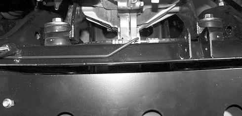
Note: When prying axles to release them from transmission use built up wide area on transmission as a leverage spot to avoid damage to bearing housing. Built up areas are located at approximately 4 and 10 oíclock positions.
10.Remove bolt from front drive shaft coupler (F) and slide coupler onto driveshaft.
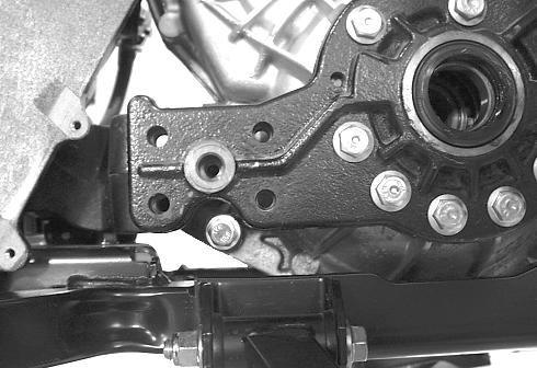
11.Remove five bolts (G) securing right angle drive to transmission. Remove right angle drive and support it to avoid strain on park brake cable.
Note pry bar location.
15.Release axle from transmission. Care taken not to damage seal area.
16.Repeat axle release from transmission for second axle.
17.Remove left and right brake calipers (H). Support calipers and brake lines.
18.Support lower A-arm. Remove lock nut and bolt (I) securing upper A-arms to suspension uprights.
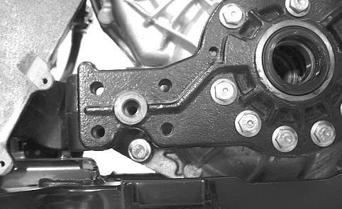
21.Remove three bolts (K) securing plate to transmission.
22.Remove bolts (L) and flange nuts securing plate to engine back plate.
23.Remove plate being careful to keep pin (M) with plate.
24.Support transmission assembly with a hoist.
19..Hold lower A-arm and remove support. Slowly lower Aarm and halfshaft while guiding bearing housing and shaft (J) out of transmission. Make sure brake lines are not getting pinched, kinked, or stretched.

20. Repeat on procedure on other side of machine.
25.Right-Hand Side: Remove eight bolts (N) from transmission mount.


26.Disconnect speed sensor connector from wiring harness.
27.Left-Hand Side: Remove five bolts to engine mount.
28.Remove center mount bolt (O) and shim(s) (P).
Shown from top
29.Remove the left-hand rear transmission mounting bolt (Q) and isolator.


Important: Avoid Damage! Do not pry on mating surfaces.
1.Install new gasket on inner left side bearing housing. Install bearing housing to transmission using eight bolts. Tighten bolts to 73 Nïm (54 lb-ft)

2.Install new seal (A). Grease inside of seal to aid axle installation.
3.If removed, install right-hand bearing holder side plate.
30.Carefully separate transmission from bearing holder side plate. Adjust hoist during separation to keep transmission parallel to side plate and from binding on alignment pins (R).

31.When alignment pins are free, tilt transmission slightly and lift it out from the machine with the hoist.
Transmission Installation
Installation:
Installation is performed in a specific sequence.
Note: Make sure the side plate is clean and dry, and has all old gasket material removed.
If necessary when installing side plate, use built up wide area on plate to tap with soft mallet to seat plate to transmission. Built up areas are located at approximately 4 and 10 oíclock positions.
Shown from top a.Install rear isolator. Tighten bolt (B) to 109 Nïm (80 lb-ft) b.Install center bolt, shim(s) and four outer bolts.
•Install shims and center bolt (C) and tighten to 25
Nïm (18 lb-ft)
•Install four outer bolts.
4.Remove old gasket material from transmission and inner axle bearing housing.
5.Check that alignment pins are in place in the transmission housing.
6.Carefully lower transmission into machine. Place new gasket on pins.Ensure that the gasket stays in place and the alignment pins (D) start to seat in right-hand bearing holder side plate.

7.Right-hand Side: Install two or more bolts (E) through side plate to transmission. Alternately tighten bolts to pull transmission to side plate.

9.Right-hand
10.Install the second isolator, washer, bolt (G) and nut. Tighten to 109 Nïm (80 lb-ft).
Note: Transmission may need to be rotated slightly up or down to insert center mount bolt. Do not install shim(s) at this time.
11.Install center mount bolt (O); start bolt into threads, do not tighten.
Suggest:
If the above button click is invalid.
Please download this document first, and then click the above link to download the complete manual.
Thank you so much for reading