5 minute read
DRIVE TRAIN REPAIR

from John Deere 650EX Trail Buck Utility ATV Service Repair Manual Instant Download (TM2160)
by kmd9iso9dkk

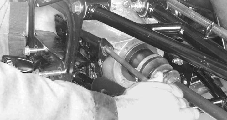
On RH side, remove drive shaft. Remove inner fender.
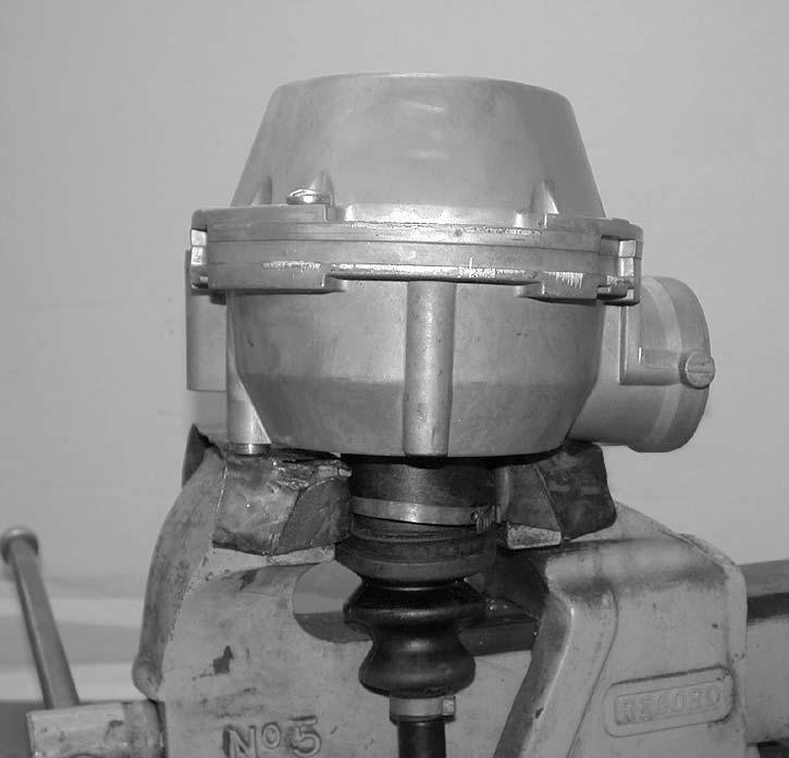
Unscrew propeller shaft bolt no.19. Differential side only. On front side, remove:
Advertisement
•front skid plate
•differential mounting bracket bolt no.4
•front mounting bolt no.3
•rear mounting bolt no.5
•differential brace no.6
•differential mounting bracket no.2.
A- Front Mounting Bolt M10 x 200 (1)
B- Differential Mounting Bracket Bolts (2)
C- Differential Mounting Bracket (3)
D- Rear Mounting Bolt M10 x 60 (4)
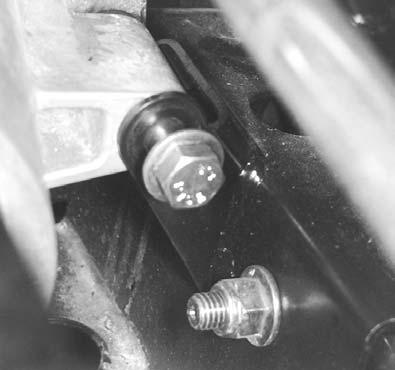
Remove rubber bellows no.15 on the top from the front differential.
Pull differential forward then separate propeller shaft no.16 from differential.
Remove front differential by the RH side. Separate LH drive shaft from differential.
Inspection:
Turn front differential gear with a finger; it should turn smoothly. Replace if necessary.
With drive shafts installed, check backlash and axial play.
Backlash Measurement and Adjustment
NOTE: Backlash adjustment is the last procedure to do before the final re-assembly of a differential.
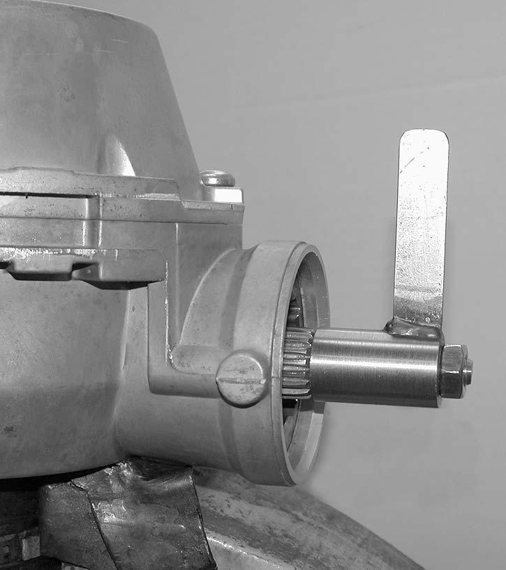
Temporarily re-assemble the differential.
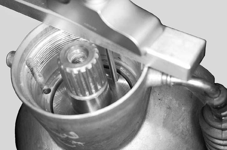
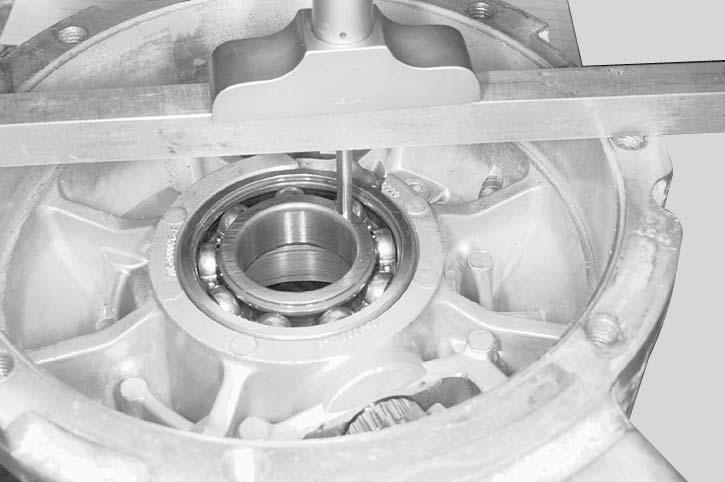
Install a drive shaft in vise then place the differential on the drive shaft end.
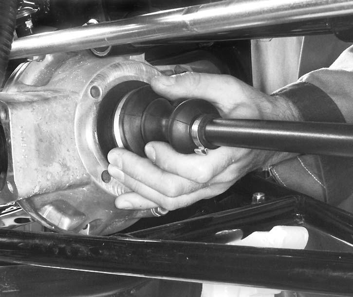
NOTE: The drive shaft prevents the gears from moving.
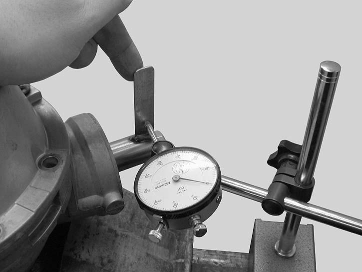
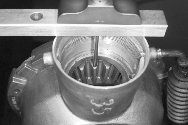
Install a backlash measurement tool at the end of the pinion gear.
A- Backlash Measurement Tool (1)
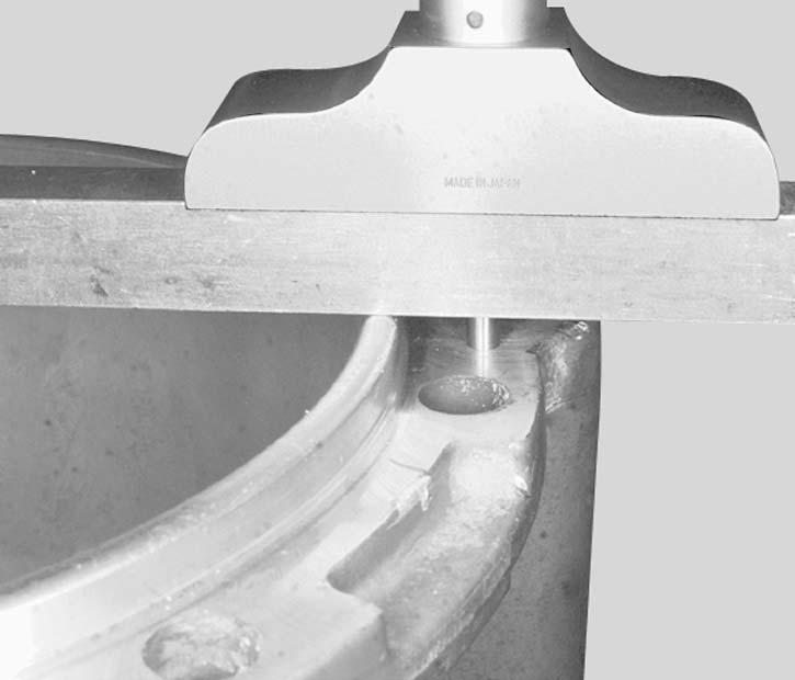
From center of bolt, measure 25.4 mm (1 in) and scribe a mark on the tab.
The reading on the dial indicator gives the backlash. To be acceptable, the backlash must be between 0.102 and 0.356 mm (0.004 and 0.014 in).
If the backlash is not within specifications, disassemble the differential and reposition the shims of the ring gear carrier accordingly in order to move it either closer to or further away from the pinion.
The backlash is adjusted by moving shims from one end of the ring gear carrier to the other as required.
IMPORTANT: Avoid damage! Never eliminate any shims, simply move them from one end to the other to be able to move the ring gear carrier either closer to or further away from the pinion in order to get the correct backlash.
Moving ring gear carrier closer to the pinion will decrease backlash. Moving it further away from the pinion will increase backlash.
Re-assemble the differential and check the backlash again. Repeat the procedure until the backlash is within specifications.
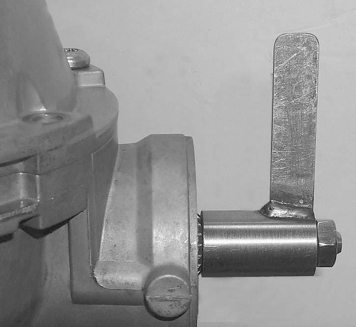
A- Tab of Backlash Measurement Tool (1)
B- Mark on Tab (2)
C- 25.4 mm (1 in.) (A)
NOTE: This measure is equal to the radius of pinion gear and is used where no specification is available.
Position the dial indicator tip against the tab at a 90-degree angle and right on the previously scribed mark. Gently move the pinion shaft back and forth.
After obtaining the proper backlash, do the final reassembly.
Disassembly:
Ring Gear Carrier/Ring Gear Removal:
To change ring gear carrier no.21 or ring gear no.22:
•Unscrew the drain plug no.23 and empty differential.
•Unscrew the TORX screws no.24, then separate half housings.
•Extract ring gear carrier with ring gear out of half housing.
•Unscrew Allen socket screws no.25 then separate ring gear from ring gear carrier.
To assembly, reverse the removal procedure. Pay attention to the following details.
NOTE: NOTE:If ring gear carrier, pinion gear, ring gear, housing or bearing is (are) changed, recenter the ring gear carrier in the housing before final assembly. See PINION GEAR AND RING GEAR CARRIER RECENTERING below.
Verify condition of half housing seal no.26. Change seal if necessary.
Check all bearings and all oil seals. Change them if necessary.
Pinion Gear Removal:
Remove oil seal no.27.
Unscrew the pinion nut no.28. Use a differential spanner socket.
Remove the bearing no.29 at the same time as the pinion gear no.30.
NOTE: The pinion gear and bearing can be easily removed using the following suggested tool:
•pipe 3-1/2” dia. x 5” (1)
•threaded rod M10 x 1.25, 7” in length (1)
•nut M10 x 1.25 (3)
•flat bar (1)
To install, reverse the removal procedure. Paying attention to the following details.
Check O-ring no.31 for damage. If so, change it. Install the shim no.32 then the ball bearing.
NOTE: If ring gear carrier, pinion gear, ring gear, housing or bearing is (are) changed, recenter the ring gear carrier in the housing before final assembly. See below.
Install the nut and a new oil seal.
Pinion Gear and Ring Gear Carrier Recentering:
NOTE: All measurements require great care and absolute cleanliness to obtain accurate results.
First; center pinion gear.
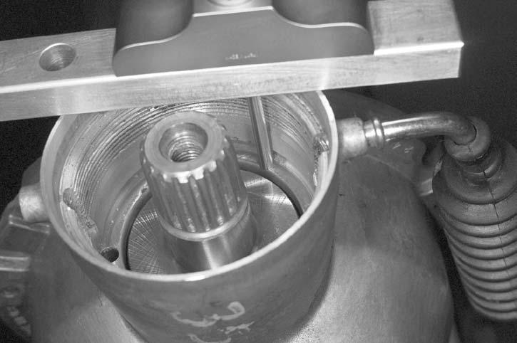
Install pinion gear into housing.
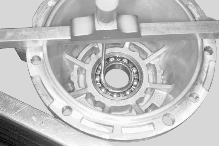
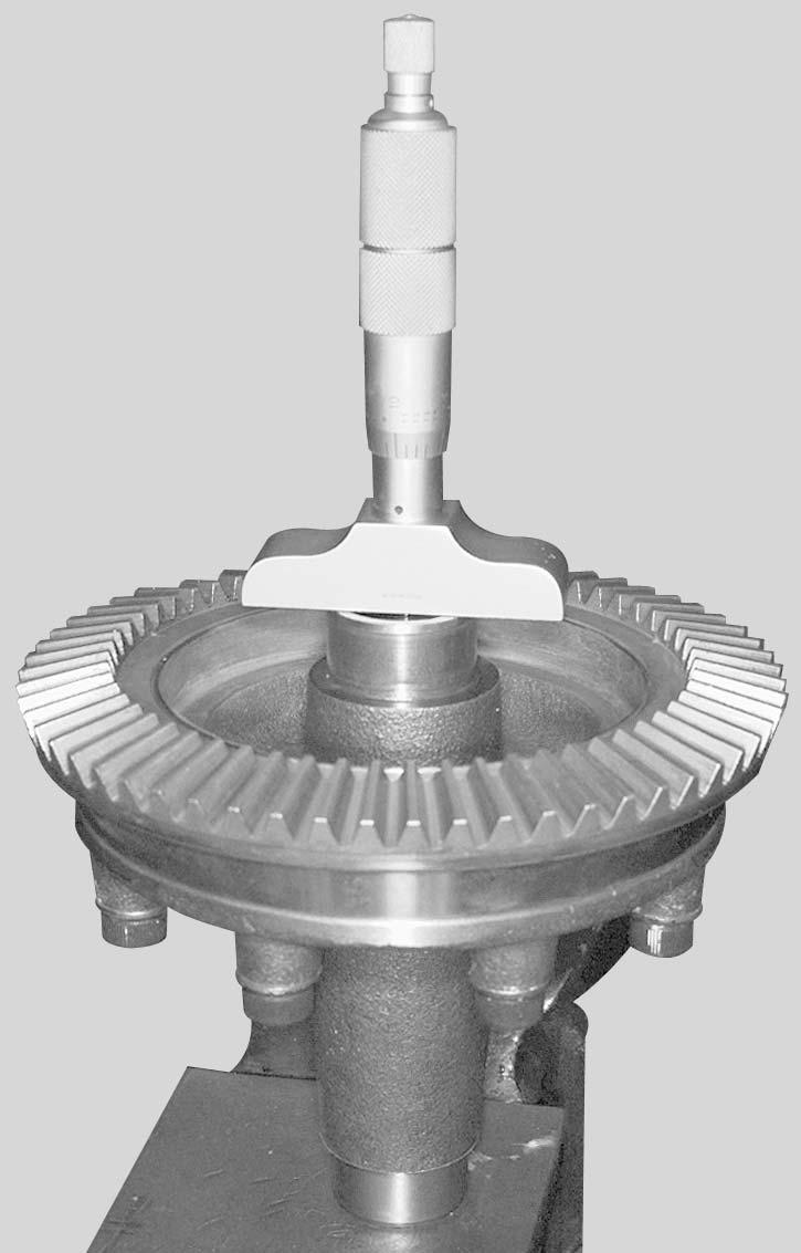
Measure distance between mount surface and the top of pinion gear. This is measure “A”.
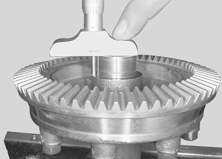
Remove pinion and install ring gear carrier with ring gear installed.
Measure distance between mount surface and the top of ring gear. This is measure “B”.
Subtract measure “B” from measure “A”. Note this result “C”.
A - B = C
Remove ring gear carrier then install pinion gear into housing.
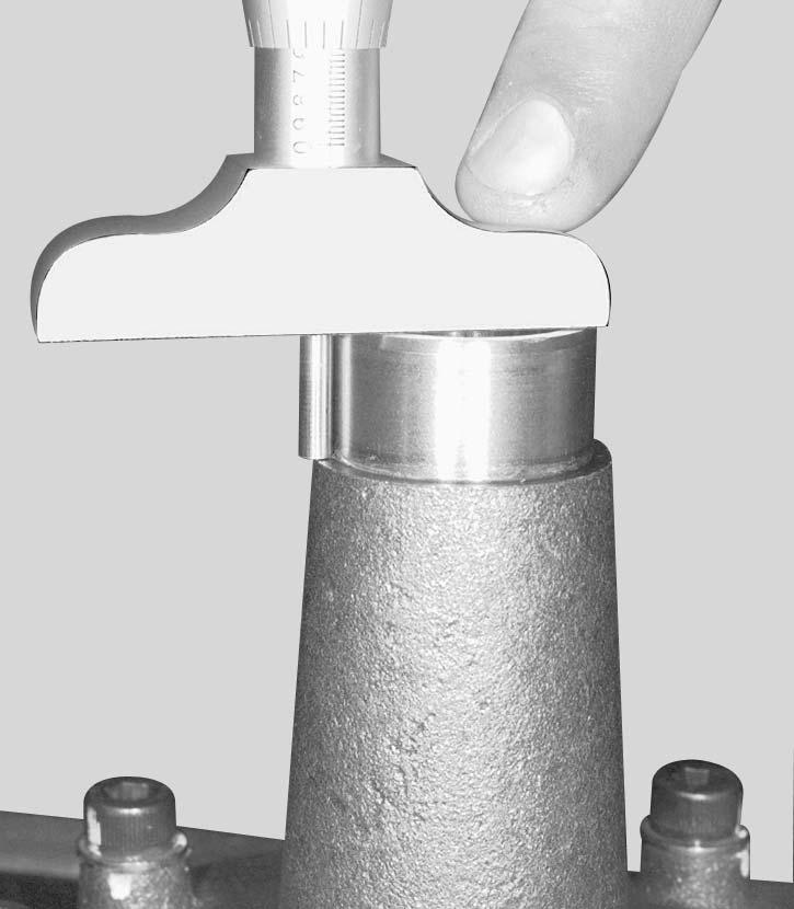
Measure distance between mounting surface and the pinion shim surface. This is measure “D”.
Remove pinion gear then measure the distance between mount surface and bearing surface. This is measure “E”.
Subtract measure “E” from measure “D”. Note this result “F”.
D - E = F
The difference between result “F” and result “C” is the pinion shims thickness.
F - C = Pinion shims thickness
Determine the appropriate pinion shim using the following pinion gear shims kit (P/N JDG 703 500 049).
ThicknessNotches
0.25 mm (0.010 in)0
0.38 mm (0.015 in)1
0.51 mm (0.020 in)2
0.56 mm (0.022 in)4
Install pinion, shims, bearing and pinion nut. Apply Loctite 243 to nut and torque to 98 N•m (72 lb-ft).
Check if pinion gear teeth and ring gear teeth are equal. After pinion installation, center ring gear carrier.
Take the half housing with pinion gear. Measure distance between housing edge and the inner ring of bearing. This is measure “G”.
Measure the other half housing between housing edge and the inner ring of bearing. This is measure “H”.
Measure the edge of half housing. This is measure “J”.
Subtract the measure “J” from measure “H” then add this result to “G”. Note this result “K”.
G + (H - J) = K (housing inside length)
Measure ring gear carrier length. This is measure “L”.
Measure the distance between the end of ring gear carrier and the bearing shoulder. Note this measure “M”.
Add measure “M” from measure “N”. Subtract this result from measure “L”. Note this result “P”.
The result “P” is the length of ring gear carrier between bearings.
L - (M + N) = P
Subtract result “P” from “K”. At this measure subtract the clearance 0.127 mm (0.005 in). The result is the shim thickness.
K - P = X - 0.127 mm (0.005 in) = shim thickness
ThicknessNotches
Take the same distance to the other end. This is measure “N”.
Determine the appropriate shim using the following ring gear carrier shims kit.
Distribute total shim thickness between both end of ring gear carrier to obtain specified backlash between ring gear and pinion gear.
V01h1Js2.EPS
Assembly and Installation:
The differential assembly is essentially the reverse of the disassembly procedure. Pay attention to the following detail.
Install the differential on the vehicle before filling oil. Refer to "Specifications" section for recommended oil.
Front Differential Oil Level:
Clean filler plug prior to check oil level. With vehicle on a level surface, check oil level by removing filler plug. Oil level must reach the lower edge. Add oil if necessary. Refer to "Specifications" section for capacity and recommended oil.