6 minute read
DRIVE TRAIN REPAIR

from John Deere 500EX Buck Utility ATV Service Repair Manual Instant Download (TM2153)
by kmd9iso9dkk
Repair
Front Drive Shaft
Advertisement
Removal:
Raise the front of vehicle, support it securely on jack stands and remove front wheel(s).
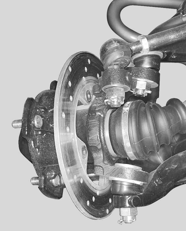
Remove wheel cap no.13, cotter pin no.12, castellated nut no.11, flat washer no.10 and O-ring no.14.
Check the O-ring for damage, replace if necessary
Remove caliper.
IMPORTANT: Avoid damage! Donít let the caliper hang by the hose and donít stretch or twist the hose.
Remove cotter pin and castellated nut from upper and lower suspension arms.
IMPORTANT: Avoid damage! Discard cotter pins. Always install new cotter pins.
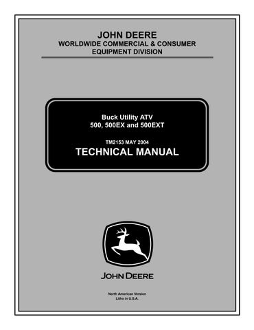
Typical
A- Castellated Nut(1)
B- Cotter Pin (2)
C- Lower Suspension Arm (3)
D- Upper Suspension Arm (4)
Detach tie-rod from knuckle.
Separate knuckle no.8, with hub and brake disk no.9, from lower and upper suspension arms.
Separate knuckle from the drive shaft no.7. Pull drive shaft out of differential no.1.
NOTE: Pull drive shaft strongly.
Inspection:
Inspect the condition of boots. If there is any damage or evidence of leaking lubricant, replace them. Refer to Drive Shaft Boot below.
Installation: v01h0fa2.EPS
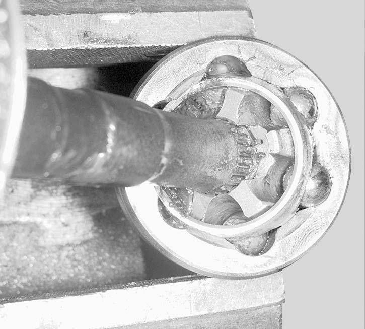
Apply grease to the splines and insert the end of drive shaft in differential and pull joint a little to make sure that the stop ring is locked in differential side gear groove.
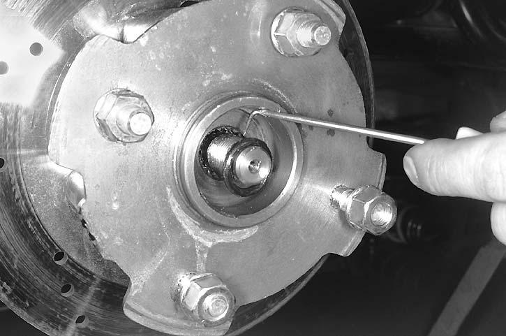
A- Stop Ring (1)
Insert the other end of drive shaft in the knuckle and install the knuckle, with hub and brake disk, to the lower and upper suspension arms. Torque the castellated nut to 47 N•m (35 lb-ft) and install a new cotter pin.
Reinstall tie-rod. Install a hardened washer on each side of the knuckle arm. Torque tie-rod castellated nut to 73 N•m (54 lb-ft) then install a new cotter pin.
Install the O-ring, the flat washer and torque the castellated nut on the drive shaft end to 135 - 155 N•m (100 - 114 lb-ft). Install a new cotter pin and the wheel cap.
Reinstall the front wheel(s) and torque nuts to 75 N•m (55 lb-ft).
Drive Shaft Boot Removal:
Remove:
•clamps from rubber boot using boot clamp pliers (P/N JDG 295 000 069 and JDG 295 000 054)
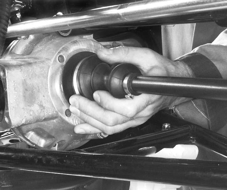
•large end of the boot from plunging joint or CV joint. Move apart circlip and pull out the shaft from bearing. Do not remove circlip.
A- Circlip (1)
B- Shaft (2)
Remove boot from drive shaft.
Inspection:
V01h0xa2.EPS
Check bearing in plunging joint or CV joint. If bearing is hard to move, change plunging joint or CV joint. Check circlip for damage, change as necessary.
Installation:
For installation, reverse the removal procedure. Paying attention to the following details.
Insert boot, do not forget the small clamp. Insert shaft and push firmly.
Pack bearing area with grease (including with the new boot kit).
NOTE: Do not use an other grease.
Front Differential
Removal:
Raise front of vehicle, support it securely on jack stands and remove front wheels.
On LH side, remove:
•wheel cap no.13
•cotter pin no.12
•castellated nut no.11
•flat washer no.10
•O-ring no.14.
Drive Train Repair
On RH side, remove drive shaft. Remove inner fender.
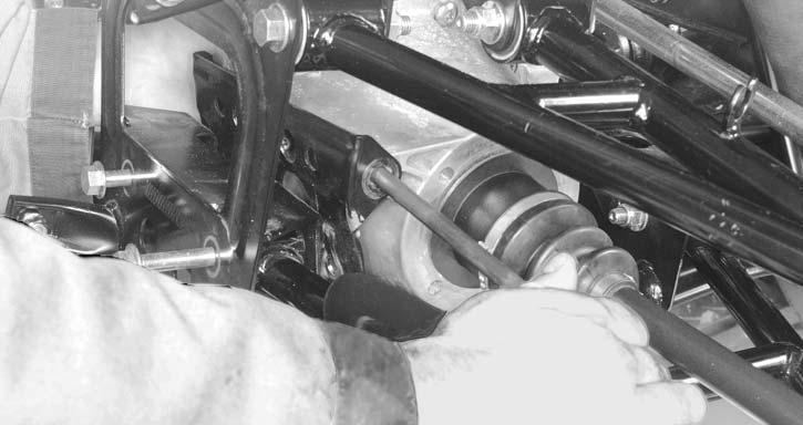
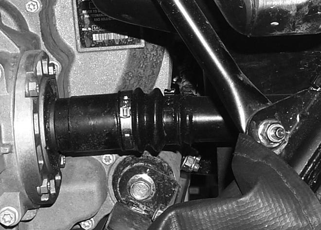
Remove clamp retaining rubber boot to differential shaft coupling.
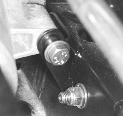
B- Differential Mounting Bracket Bolts (2)
C- Differential Mounting Bracket (3)
D- Rear Mounting Bolt M10 x 60 (4)
Remove rubber bellows no.15 on the top from the front differential.
Remove bolt no. 19 and washer no. 20 retaining shaft coupling to front differential. Remove shaft coupling.
Pull differential forward then separate propeller shaft no.16 from differential.
A- Remove Clamp (1)
On front side, remove:
•front skid plate
•differential mounting bracket bolt no.4
•front mounting bolt no.3
•rear mounting bolt no.5
•differential brace no.6
•differential mounting bracket no.2.
Remove front differential by the RH side. Separate LH drive shaft from differential.
Inspection:
Turn front differential gear with a finger; it should turn smoothly. Replace if necessary.
With drive shafts installed, check backlash and axial play.
Backlash Measurement and Adjustment
NOTE: Backlash adjustment is the last procedure to do before the final re-assembly of a differential.
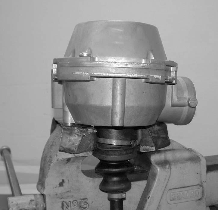
Temporarily re-assemble the differential.
Install a drive shaft in vise then place the differential on the drive shaft end.
A- Front Mounting Bolt M10 x 200
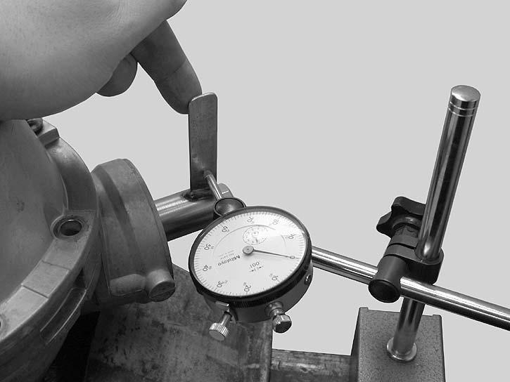
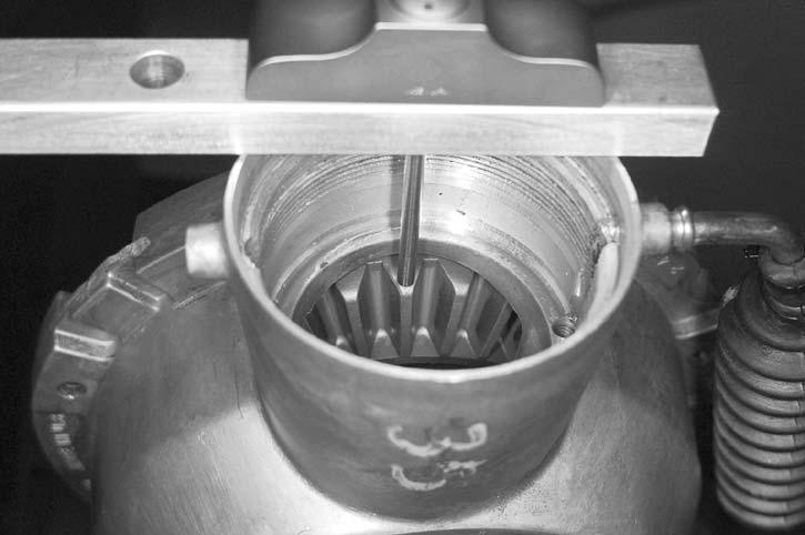
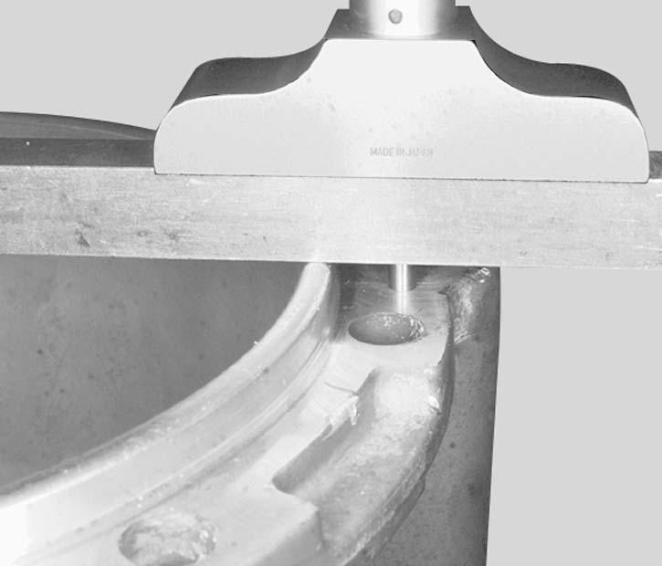
NOTE: The drive shaft prevents the gears from moving. Install a backlash measurement tool at the end of the pinion gear.
V04h0lA2.EPS
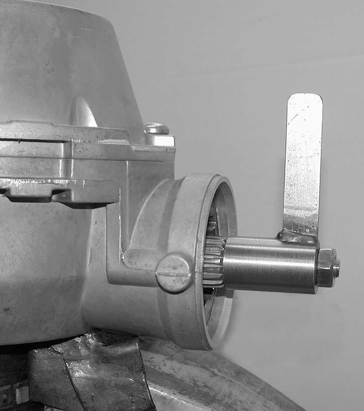
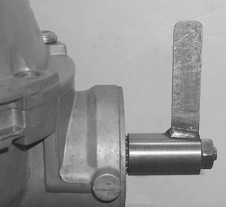
A- Tab of Backlash Measurement Tool (1)
B- Mark on Tab (2)
C- 25.4 mm (1 in.) (A)
NOTE: This measure is equal to the radius of pinion gear and is used where no specification is available. Position the dial indicator tip against the tab at a 90-degree angle and right on the previously scribed mark. Gently move the pinion shaft back and forth.
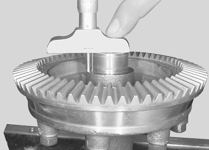
V04h0kA2.EPS
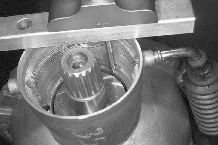
A- Backlash Measurement Tool (1)
From center of bolt, measure 25.4 mm (1 in) and scribe a mark on the tab.
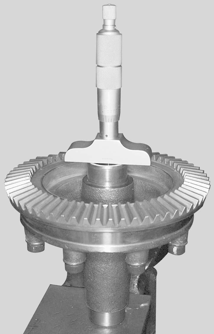
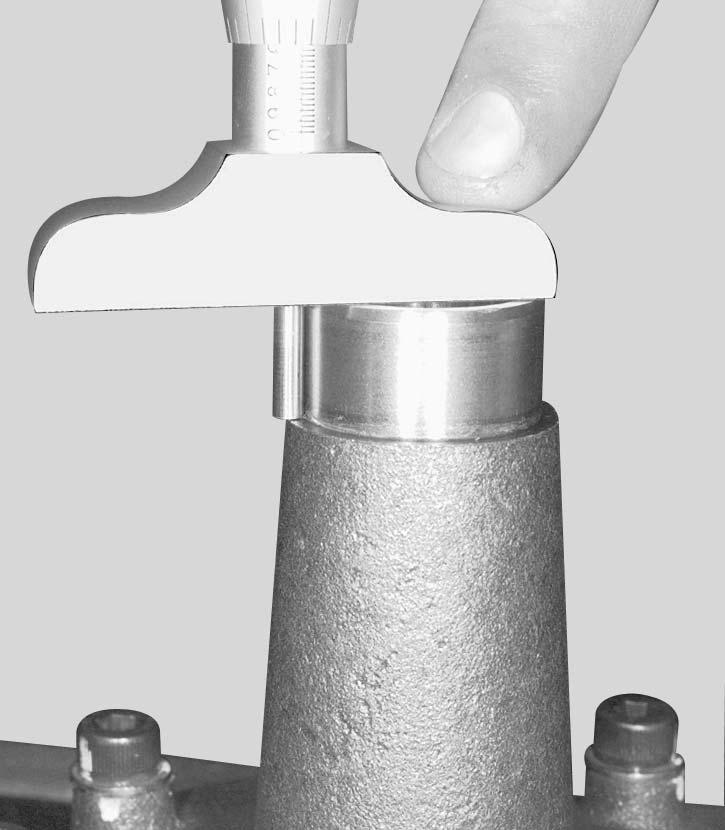
V04h0mA2.EPS
The reading on the dial indicator gives the backlash. To be acceptable, the backlash must be between 0.102 and 0.356 mm (0.004 and 0.014 in).
If the backlash is not within specifications, disassemble the differential and reposition the shims of the ring gear carrier accordingly in order to move it either closer to or further away from the pinion.
The backlash is adjusted by moving shims from one end of the ring gear carrier to the other as required.
IMPORTANT: Avoid damage! Never eliminate any shims, simply move them from one end to the other to be able to move the ring gear carrier either closer to or further away from the pinion in order to get the correct backlash.
Moving ring gear carrier closer to the pinion will decrease backlash. Moving it further away from the pinion will increase backlash.
Re-assemble the differential and check the backlash again. Repeat the procedure until the backlash is within specifications.
After obtaining the proper backlash, do the final reassembly.
Disassembly:
Ring Gear Carrier/Ring Gear Removal:
To change ring gear carrier no.21 or ring gear no.22:
•Unscrew the drain plug no.23 and empty differential.
•Unscrew the TORX screws no.24, then separate half housings.
•Extract ring gear carrier with ring gear out of half housing.
•Unscrew Allen socket screws no.25 then separate ring gear from ring gear carrier.
To assembly, reverse the removal procedure. Pay attention to the following details.
NOTE: NOTE:If ring gear carrier, pinion gear, ring gear, housing or bearing is (are) changed, recenter the ring gear carrier in the housing before final assembly. See PINION GEAR AND RING GEAR CARRIER RECENTERING below.
Verify condition of half housing seal no.26. Change seal if necessary.
Check all bearings and all oil seals. Change them if necessary.
Pinion Gear Removal:
Remove oil seal no.27.
Unscrew the pinion nut no.28. Use a differential spanner socket.
Remove the bearing no.29 at the same time as the pinion gear no.30.
NOTE: The pinion gear and bearing can be easily removed using the following suggested tool:
•pipe 3-1/2” dia. x 5” (1)
•threaded rod M10 x 1.25, 7” in length (1)
•nut M10 x 1.25 (3)
•flat bar (1)
To install, reverse the removal procedure. Paying attention to the following details.
Check O-ring no.31 for damage. If so, change it. Install the shim no.32 then the ball bearing.
NOTE: If ring gear carrier, pinion gear, ring gear, housing or bearing is (are) changed, recenter the ring gear carrier in the housing before final assembly. See below.
Install the nut and a new oil seal.
Pinion Gear and Ring Gear Carrier Recentering:
NOTE: All measurements require great care and absolute cleanliness to obtain accurate results.
First; center pinion gear.
Install pinion gear into housing.
Measure distance between mount surface and the top of pinion gear. This is measure “A”.
Remove pinion and install ring gear carrier with ring gear installed.
Measure distance between mount surface and the top of ring gear. This is measure “B”.
Subtract measure “B” from measure “A”. Note this result “C”.
A - B = C
Remove ring gear carrier then install pinion gear into housing.
Measure distance between mounting surface and the pinion shim surface. This is measure “D”.
Remove pinion gear then measure the distance between mount surface and bearing surface. This is measure “E”.


Take the half housing with pinion gear. Measure distance between housing edge and the inner ring of bearing. This is measure “G”.
Subtract measure “E” from measure “D”. Note this result “F”.
D - E = F
The difference between result “F” and result “C” is the pinion shims thickness.
F - C = Pinion shims thickness
Determine the appropriate pinion shim using the following pinion gear shims kit (P/N JDG 703 500 049).
ThicknessNotches
0.25 mm (0.010 in)0
0.38 mm (0.015 in)1
0.51 mm (0.020 in)2
0.56 mm (0.022 in)4
Install pinion, shims, bearing and pinion nut. Apply Loctite 243 to nut and torque to 98 N•m (72 lb-ft).
Check if pinion gear teeth and ring gear teeth are equal. After pinion installation, center ring gear carrier.
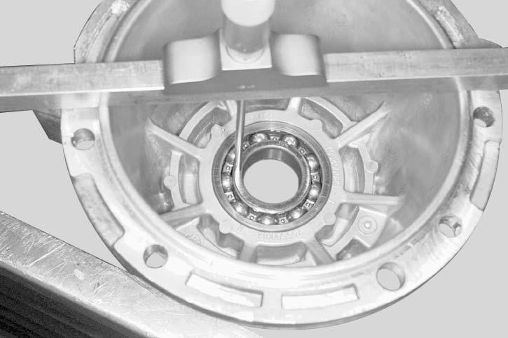
Measure the other half housing between housing edge and the inner ring of bearing. This is measure “H”.
Measure the edge of half housing. This is measure “J”.
Subtract the measure “J” from measure “H” then add this result to “G”. Note this result “K”.
G + (H - J) = K (housing inside length)
Measure ring gear carrier length. This is measure “L”.
Take the same distance to the other end. This is measure “N”.
Measure the distance between the end of ring gear carrier and the bearing shoulder. Note this measure “M”.
Add measure “M” from measure “N”. Subtract this result from measure “L”. Note this result “P”.
The result “P” is the length of ring gear carrier between bearings.
L - (M + N) = P
Subtract result “P” from “K”. At this measure subtract the clearance 0.127 mm (0.005 in). The result is the shim thickness.
K - P = X - 0.127 mm (0.005 in) = shim thickness
ThicknessNotches
0.25 mm (0.010 in)0
0.38 mm (0.015 in)1
0.51 mm (0.020 in)2
0.64 mm (0.025 in)3