8 minute read
Installation Procedure NOTICE

from Caterpillar Cat 422E BACKHOE LOADER (Prefix MAW) Service Repair Manual Instant Download
by kmd9iso9dkk

Keep all parts clean from contaminants.
Contaminants may cause rapid wear and shortened component life.
Advertisement
Illustration 2
Typical example g00952432
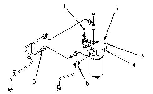
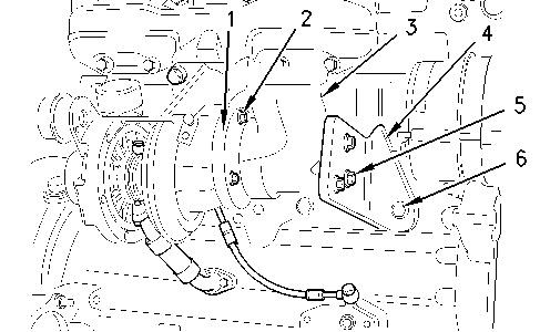
1. Clean the external surfaces of the fuel priming pump (4). Position the fuel priming pump (4) and install the setscrews (1) and new rubber washers.
2. Remove the dust covers from the fuel priming pump. Remove the plugs from the tube assemblies. Connect the tube assembly (5). Connect the tube assembly (6).
3. Connect the fuel return line to the connector (3).
4. Connect the harness assembly to the connector (2).
5. Remove the air from the fuel system. Refer to the Operations and Maintenance Manual, "Fuel System - Prime".
Copyright 1993 - 2019 Caterpillar Inc. All Rights Reserved. Private
Shutdown SIS
Previous Screen
Product: BACKHOE LOADER
Model: 422E BACKHOE LOADER MAW
Configuration: 422E Backhoe Loader MAW00001-UP (MACHINE) POWERED BY C4.4 Engine
Disassembly and Assembly
3054C Engines for Caterpillar Built Machines
Fuel Injection Lines - Remove and Install
SMCS - 1252-010
Removal Procedure
Table 1
Required Tools
Note: SERVICE DATA: TOOLING (ZZ) WILL NOT BE IDENTIFIED IN PHOTOGRAPHS IN THE REMOVAL OR THE INSTALLATION. THIS TOOLING IS SHOWN IN ORDER TO ASSIST THE EXPERIENCED SERVICEMAN.
NOTICE
Keep all parts clean from contaminants.
Contaminants may cause rapid wear and shortened component life.
NOTICE
Care must be taken to ensure that fluids are contained during performance of inspection, maintenance, testing, adjusting, and repair of the product. Be prepared to collect the fluid with suitable containers before opening any compartment or disassembling any component containing fluids.
Refer to Special Publication, NENG2500, "Dealer Service Tool Catalog" for tools and supplies suitable to collect and contain fluids on Cat products.
Dispose of all fluids according to local regulations and mandates.
Illustration 2 g01001381
2. Disconnect fuel injection lines (3) at fuel injection nozzles (4).
3. Disconnect fuel injection lines (3) at fuel injection pump (5).
4. Remove the fuel injection lines.
Installation Procedure
Notice
Keep all parts clean from contaminants. Contaminants may cause rapid wear and shortened component life.
Illustration 3 g01001381
1. Connect fuel injection lines (3) at fuel injection nozzles (4). Tighten the nut to 30 N·m (22 lb ft).
2. Connect the fuel injection lines at fuel injection pump (5). Tighten the nut to 30 N·m (22 lb ft).
3. Remove the air from the fuel system. Refer to Operations and Maintenance Manual, "Fuel System - Prime".
Illustration 4 g01001306
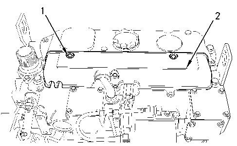
4. Position cover (2) on the cylinder head. Install bolts (1). Tighten the bolts to a torque of 9 N·m (80 lb in).
Copyright 1993 - 2019 Caterpillar Inc.
Previous Screen
Product: BACKHOE LOADER
Model: 422E BACKHOE LOADER MAW
Configuration: 422E Backhoe Loader MAW00001-UP (MACHINE) POWERED BY C4.4 Engine
Disassembly and Assembly
3054C Engines for Caterpillar Built Machines
Fuel Injection Nozzles - Remove
SMCS - 1254-011
Removal Procedure
Start By: a. Remove the fuel injection lines. Refer to Disassembly and Assembly, "Fuel Injection Lines - Remove and Install".
Notice
Keep all parts clean from contaminants.
Contaminants may cause rapid wear and shortened component life.
Notice
Care must be taken to ensure that fluids are contained during performance of inspection, maintenance, testing, adjusting, and repair of the product. Be prepared to collect the fluid with suitable containers before opening any compartment or disassembling any component containing fluids.
Refer to Special Publication, NENG2500, "Dealer Service Tool Catalog" for tools and supplies suitable to collect and contain fluids on Cat products.
Dispose of all fluids according to local regulations and mandates.
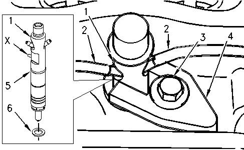
1. Remove hose (2) from fuel injection nozzle (1).
2. Remove bolt (3). Remove clamp (4) from the fuel injection nozzle.
3. Remove the fuel injection nozzle from the cylinder head. Remove O-ring seal (5) from the fuel injection nozzle.
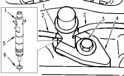
4. Remove seat washer (6) from the cylinder head.
Note: If the original seat washer is not removed, the projection of the fuel injection nozzle will be incorrect when a new seat washer is installed.
Previous Screen
Product: BACKHOE LOADER
Model: 422E BACKHOE LOADER MAW
Configuration: 422E Backhoe Loader MAW00001-UP (MACHINE) POWERED BY C4.4 Engine
Disassembly and Assembly
3054C Engines for Caterpillar Built Machines
Fuel Injection Nozzles - Install
SMCS - 1254-012
Installation Procedure
Notice
Keep all parts clean from contaminants.
Contaminants may cause rapid wear and shortened component life.
Shutdown SIS
1. Lubricate seat washer (6) with clean engine oil. Install the seat washer in the cylinder head.
Note: If the original seat washer is reused, the projection of the fuel injection nozzle will be incorrect.
2. Install O-ring seal (5) on fuel injection nozzle (1). Install the fuel injection nozzle in the cylinder head.
Note: Alignment Pin (X) must be located opposite clamp (4).
3. Position clamp (4) on the fuel injection nozzle. Install bolt (3). Tighten the bolt to a torque of 27 N·m (20 lb ft).
4. Install hose (2) to the fuel injection nozzle.
End By: a. Install the fuel injection lines. Refer to Disassembly and Assembly, "Fuel Injection LinesRemove and Install".
Copyright 1993 - 2019 Caterpillar Inc.
Previous Screen
Product: BACKHOE LOADER
Model: 422E BACKHOE LOADER MAW
Configuration: 422E Backhoe Loader MAW00001-UP (MACHINE) POWERED BY C4.4 Engine
Disassembly and Assembly
3054C Engines for Caterpillar Built Machines
Fuel Injection Pump - Remove - Delphi DP210
SMCS - 1251-011
Removal Procedure Table 1
Required Tools
Start By: a. Remove the fuel injection lines. Refer to Disassembly and Assembly, "Fuel Injection Lines - Remove and Install". b. Remove the crankshaft pulley. Refer to Disassembly and Assembly, "Crankshaft PulleyRemove and Install". c. Remove the front cover. Refer to Disassembly and Assembly, "Front Cover - Remove and Install". d. Remove the air compressor, if equipped. Refer to Disassembly and Assembly, "Air Compressor - Remove and Install".
Note: SERVICE DATA: TOOLING (ZZ) WILL NOT BE IDENTIFIED IN PHOTOGRAPHS IN THE REMOVAL OR THE INSTALLATION. THIS TOOLING IS SHOWN IN ORDER TO ASSIST THE EXPERIENCED SERVICEMAN.
Notice
Keep all parts clean from contaminants.
Contaminants may cause rapid wear and shortened component life.
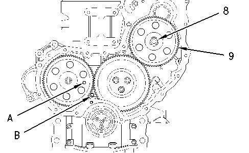
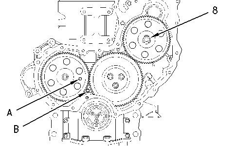
1. Use Tooling (C) to ensure that the No. 1 cylinder is at the top center compression stroke. Refer to Testing and Adjusting, "Finding Top Center Position for No. 1 Piston".
Note: Install Tooling (A) through the camshaft gear. Install Tooling (B) into the crankshaft web.
Notice
The locking bolt must not be loosened under any circumstances while the pump is off the engine. If the shaft is moved, dynamic timing of the pump will be lost. Reestablishing timing must be done by an authorized Delphi dealer, and is not a warrantable expense.
2. Loosen bolt (5). Move spacer (6) in order to allow bolt (5) to tighten against the shaft of the fuel injection pump. Rotate the fuel injection pump gear in a counterclockwise direction in order to remove the backlash. Tighten bolt (5) to a torque of 17 N·m (13 lb ft).
Note: Bolt (5) must be tightened in order to prevent the shaft of the fuel injection pump from rotating.
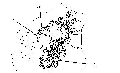
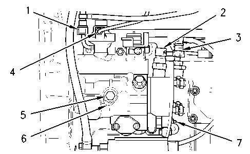
3. Disconnect fuel return line (1). Disconnect tube assembly (4) from the fuel injection pump.
4. Disconnect harness assembly (2). Disconnect fuel line (3).
5. Disconnect the harness assembly from timing advance solenoid (7).
Illustration 2 g00956200
6. Remove nut (8) and the washer from the shaft of the fuel injection pump.
7. Install Tooling (D) and remove fuel injection pump gear (9).
Note: Do Not pry the fuel injection pump gear from the shaft of the fuel injection pump.
8. Remove nut (14). Remove bolt (12).
9. If necessary, remove bolt (15) and bracket (11) from the cylinder block.
10. Remove bolts (13) in order to remove the fuel injection pump.
11. Remove the fuel injection pump from the front housing. Remove O-ring seal (10) from the fuel injection pump.
Previous Screen
Product: BACKHOE LOADER
Model: 422E BACKHOE LOADER MAW
Configuration: 422E Backhoe Loader MAW00001-UP (MACHINE) POWERED BY C4.4 Engine
Disassembly and Assembly
3054C Engines for Caterpillar Built Machines
Fuel Injection Pump - Install - Delphi DP210
SMCS - 1251-012
Installation Procedure Table 1
Required Tools
A 230-6284 Timing Pin (Camshaft) 1
B 230-6283 Timing Pin (Crankshaft) 1
C 9U-6198 Crankshaft Turning Tool 1
D 1U-6396 O-Ring Assembly Compound 1
NOTICE
Keep all parts clean from contaminants.
Contaminants may cause rapid wear and shortened component life.
Shutdown SIS
1. Use Tooling (C) to ensure that the No. 1 cylinder is at the top center compression stroke. Refer to Testing and Adjusting, "Fuel Injection Timing - Check".
Note: Install Tooling (A) through the camshaft gear. Install Tooling (B) through the crankshaft web.
Illustration 1 g00956267
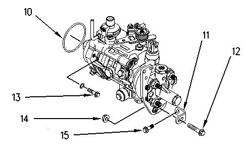
2. Use Tooling (D) in order to lubricate O-ring seal (10). Install a new O-ring seal (10) onto the fuel injection pump.
3. Install new washers to bolts (13).
4. Align the holes in the fuel injection pump with the holes in the front housing. Install the fuel injection pump to the housing.
Note: The fuel injection pump should be supported by hand until the bolts are installed.
5. Install bolts (13). Tighten bolts (13) to a torque of 22 N·m (16 lb ft).
6. Position support bracket (11) onto the cylinder block. Install bolt (15) finger tight.
7. Install bolt (12) and nut (14) finger tight.
8. Tighten bolt (12) and nut (14) to a torque of 22 N·m (16 lb ft). Tighten bolt (15) to a torque of 44 N·m (32 lb ft).
Note: Ensure that the fuel injection pump is not stressed as the bolts for the bracket are tightened.
Illustration 2 g00956200
Note: Ensure that the mating surfaces of the fuel injection pump gear and the shaft of the fuel injection pump are clean. Lubricate the threads of the shaft for the fuel injection pump. The nut must turn freely until contact is made with the fuel injection pump gear.
9. Position fuel injection pump gear (9) on the shaft of the fuel injection pump. Install the washer and nut (8). Rotate the fuel injection pump gear in a counterclockwise direction in order to remove the backlash. Tighten nut (8) to a torque of 24 N·m (17 lb ft).
Illustration 3 g00956204
10. Connect the harness assembly to timing advance solenoid (7).
11. Connect harness assembly (2). Connect fuel line (3).
12. Connect fuel return line (1). Connect tube assembly (4) to the fuel injection pump.
13. Loosen bolt (5). Move spacer (6) in order to prevent bolt (5) from tightening against the shaft of the fuel injection pump. Tighten bolt (5) to a torque of 12 N·m (106 lb in).
Note: Spacer (6) must be correctly positioned and bolt (5) must be tightened in order to prevent the bolt from contacting the shaft of the fuel injection pump.
14. Tighten nut (8) to a torque of 88 N·m (65 lb ft).
15. Remove Tooling (A) and Tooling (B).
End By: a. Install the front cover. Refer to Disassembly and Assembly, "Front Cover - Remove and Install". b. Install the crankshaft pulley. Refer to Disassembly and Assembly, "Crankshaft PulleyRemove and Install". c. Install the fuel injection lines. Refer to Disassembly and Assembly, "Fuel Injection LinesRemove and Install". d. Install the air compressor, if equipped. Refer to Disassembly and Assembly, "Air Compressor - Remove and Install".
Copyright 1993 - 2019 Caterpillar Inc. All Rights Reserved.
Previous Screen
Product: BACKHOE LOADER
Model: 422E BACKHOE LOADER MAW
Configuration: 422E Backhoe Loader MAW00001-UP (MACHINE) POWERED BY C4.4 Engine
Disassembly and Assembly
3054C Engines for Caterpillar Built Machines
Turbocharger - Remove
SMCS - 1052-011
Removal Procedure
Notice
Keep all parts clean from contaminants.
Contaminants may cause rapid wear and shortened component life.
NOTICE
Care must be taken to ensure that fluids are contained during performance of inspection, maintenance, testing, adjusting, and repair of the product. Be prepared to collect the fluid with suitable containers before opening any compartment or disassembling any component containing fluids.
Refer to Special Publication, NENG2500, "Dealer Service Tool Catalog" for tools and supplies suitable to collect and contain fluids on Cat products.
Dispose of all fluids according to local regulations and mandates.
1.
2. Loosen the hose clamps and remove the air inlet hose at the turbocharger compressor housing.
Note: The exhaust elbow is an option.
3. Remove the exhaust pipe from the turbocharger outlet or remove the exhaust pipe from the exhaust elbow, if equipped. Refer to the OEM provided information for the correct procedure in order to remove the exhaust pipe.
Illustration 1 g00975635
4. Remove the setscrews (5) from the exhaust elbow (3), if equipped.
5. Remove the setscrews (6) and remove the bracket (4) from the cylinder block.
6. If equipped, remove the exhaust elbow (3) from the exhaust adapter (1).
7. Remove the nuts (2) and remove the exhaust adapter (1) from the turbocharger.
8. Place a suitable container below the turbocharger (1) in order to collect any spillage of oil.
Suggest:
If the above button click is invalid.
Please download this document first, and then click the above link to download the complete manual.
Thank you so much for reading