
4 minute read
Service Repair Manual Model

from Caterpillar Cat 226D SKID STEER LOADER (Prefix HRD) Service Repair Manual Instant Download
by kmd9iso9dkk

226d Skid Steer Loader
Shutdown SIS
Advertisement
Previous Screen
Product: SKID STEER LOADER
Model: 226D SKID STEER LOADER HRD
Configuration: 226D Skid Steer Loader HRD00001-UP (MACHINE) POWERED BY C2.2 Engine
Disassembly and Assembly
C2.2 Engines for Caterpillar Built Machines
Fuel Injection Lines - Remove and Install
SMCS - 1252-010
Fuel Injection Lines Remove
Contact with high pressure fuel may cause fluid penetration and burn hazards. High pressure fuel spray may cause a fire hazard. Failure to follow these inspection, maintenance and service instructions may cause personal injury or death.
Table 1
Required Tools
Tool Part Number Part Description Qty
A 491-1265 Capping Kit 1
NOTICE
Ensure that all adjustments and repairs that are carried out to the fuel system are performed by authorized personnel that have the correct training.
Before beginning ANY work on the fuel system, refer to Operation and Maintenance Manual, "General Hazard Information and High Pressure Fuel Lines" for safety information.
Refer to System Operation, Testing and Adjusting, "Cleanliness of Fuel System Components" for detailed information on the standards of cleanliness that must be observed during ALL work on the fuel system.
Notice
Care must be taken to ensure that fluids are contained during performance of inspection, maintenance, testing, adjusting and repair of the product. Be prepared to collect the fluid with suitable containers before opening any compartment or disassembling any component containing fluids.
Dispose of all fluids according to local regulations and mandates.
Turn the fuel supply to the OFF position. Turn the battery disconnect switch to the OFF position.
If necessary, remove the breather hoses, refer to this Disassembly and Assembly, "Crankcase Breather - Remove and Install" for more information.
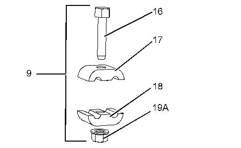

2. Remove bolt (16) and nut (19A) from clamp assembly (9). Remove isolators (17) and (18). Remove bolt nut and isolators from clamp (12).
3. Disconnect nut (8) and nut (14). Remove fuel injection line (7). Install Tooling (A) to the fuel injector and the fuel manifold (20) as soon as the fuel injection line is removed.
4. Disconnect nut (5) and nut (13). Remove fuel injection line (6). Install Tooling (A) to the fuel injector and the fuel manifold (20) as soon as the fuel injection line is removed.
5. Disconnect nut (3) and nut (11). Remove fuel injection line (4). Install Tooling (A) to the fuel injector and the fuel manifold (20) as soon as the fuel injection line is removed.
6. Disconnect nut (1) and nut (10). Remove fuel injection line (2). Install Tooling (A) to the fuel injector and the fuel manifold (20) as soon as the fuel injection line is removed.
7. Discard all fuel injection lines
8. Disconnect nut (19) and nut (23). Remove fuel injection line (22) from manifold (20) and pump (24). Install Tooling (A) to the fuel pump and fuel manifold (20) as soon as the fuel injection line is removed. Discard the fuel injection line.
Fuel Injection Lines Install
Notice
All plugs and caps must be remain in position until the component is about to be installed
Illustration 4 g03816588
1. Position fuel injection line (22) onto fuel rail (20) and pump (24). Tighten nut (19) and nut (23) to a torque of 22.5 N·m (199 lb in).
Illustration 5 g03816505
2. Position fuel injection line (2) onto fuel rail (20) and fuel injector. Loosely install fuel injection line. Position fuel injection line (4) onto fuel rail (20) and fuel injector. Loosely install fuel injection line. Illustration
3. Position isolator (18) and isolator (17) onto fuel injection lines (2) and (4). Install nut (19A) and bolt (16). Tighten nut and bolt to a torque of 10 N·m (89 lb in).
4. Tighten nut (1) and nut (10) to a torque of 22.5 N·m (199 lb in). Tighten nut (3) and nut (11) to a torque of 22.5 N·m (199 lb in)
5. Position fuel injection line (6) onto fuel rail (20) and fuel injector. Loosely install fuel injection line. Position fuel injection line (7) onto fuel rail (20) and fuel injector. Loosely install fuel injection line.
6. Align isolator (18) and isolator (17) onto fuel injection lines (6) and (7). Install nut (19) and bolt (16). Tighten nut and bolt to a torque of 10 N·m (89 lb in).
7. Tighten nut (5) and nut (13) to a torque of 22.5 N·m (199 lb in). Tighten nut (8) and nut (14) to a torque of 22.5 N·m (199 lb in)
8. Turn the fuel supply to the ON position and turn the battery disconnect switch to the ON position. If necessary, install breather hoses refer to this Disassembly and Assembly, "Crankcase Breather - Remove and Install" for more information.
9. Remove the air from the fuel system. Refer to Operation and Maintenance Manual, "Fuel System Prime" for more information.
Copyright 1993 - 2019 Caterpillar Inc. All Rights Reserved. Private Network For SIS Licensees.
Shutdown SIS
Previous Screen
Product: SKID STEER LOADER
Model: 226D SKID STEER LOADER HRD
Configuration: 226D Skid Steer Loader HRD00001-UP (MACHINE) POWERED BY C2.2 Engine
Disassembly and Assembly
C2.2 Engines for Caterpillar Built Machines
Exhaust Cooler (NRS) - Remove and Install - 4 Cylinder
Engines
SMCS - 1087; 108C-010
Removal Procedure
Start By: a. Drain the coolant from the cooling system into a suitable container for storage or disposal. Refer to Operation and Maintenance Manual, "Cooling System Coolant - Change" for the correct procedure. b. Disconnect the air induction hose from the turbocharger. Refer to Disassembly and assembly, "Turbocharger - Remove" for the correct procedure.
Sulfuric Acid Burn Hazard may cause serious personal injury or death.
The exhaust gas cooler may contain a small amount of sulfuric acid. The use of fuel with sulfur levels greater than 15 ppm may increase the amount of sulfuric acid formed. The sulfuric acid may spill from the cooler during service of the engine. The sulfuric acid will burn the eyes, skin and clothing on contact. Always wear the appropriate personal protective equipment (PPE) that is noted on a material safety data sheet (MSDS) for sulfuric acid. Always follow the directions for first aid that are noted on a material safety data sheet (MSDS) for sulfuric acid.
Illustration 1
Alternator removed for clarity g03815985
1. Loosen hose clamp (10) on hose assembly (11). Disconnect hose assembly (11) from exhaust cooler (NRS) (7).
2. Loosen hose clamp (9) on hose assembly (8). Disconnect hose assembly (8) from exhaust cooler NRS) (7).
3. Remove bolts (2) and nuts (6) from tube assembly (1).
4. Remove tube assembly (1) from exhaust cooler (NRS) (7) and exhaust gas recirculation (EGR) valve assembly (3).
5. Remove gasket (4) (not shown) and gasket (5) (not shown).

Illustration 2
Typical example g03816340
6. Remove bolts (12) from exhaust cooler (NRS) assembly (7).
7. Remove gasket (14) (not shown) from between exhaust manifold (13) and exhaust cooler (NRS) assembly (7).
8. Remove nut (18) from bracket (17). Support exhaust cooler (NRS) assembly (7) as the bolt is removed.
9. Remove exhaust cooler (NRS) assembly (7).
10. If necessary, remove studs (15) from exhaust cooler (NRS) assembly (7).
11. Plug and cap all open ports on exhaust cooler (NRS) assembly (7).
12. If necessary, remove bolt (16) and remove bracket (17).

