8 minute read
CX460 Crawler Excavators Table of Contents

* Consult the Engine Service Manual Sections to be distributed at a later date
NOTE: CNH Company reserves the right to make changes in the specification and design of the machine without prior notice and without incurring any obligation to modify units previously sold.
Advertisement
The description of the models shown in this manual has been made in accordance with the technical specifications known as of the date of design of this document.
Section
SAFETY, GENERAL INFORMATION AND STANDARD TORQUE DATA
General Information
Cleaning
Clean all metal parts except bearings, in a suitable cleaning solvent or by steam cleaning. Do not use caustic soda for steam cleaning. After cleaning, dry and put oil on all parts. Clean oil passages with compressed air. Clean bearings in a suitable cleaning solvent. Dry the bearings completely and put oil on the bearings.
Inspection
Check all parts when the parts are disassembled. Replace all parts that have wear or damage. Small scoring or grooves can be removed with a hone or crocus cloth. Complete a visual inspection for indications of wear, pitting and the replacement of parts necessary to prevent early failures.
Bearings
Check bearings for easy action. If bearings have a loose fit or rough action, replace the bearing. Wash bearings with a suitable cleaning solvent and permit to air dry. DO NOT DRY BEARINGS WITH COMPRESSED AIR.
Needle Bearings
Before you press needle bearings in a bore always remove any metal protrusions in the bore or edge of the bore. Before you press bearings into position, put petroleum jelly on the inside and outside diameter of the bearings.
Gears
Check all gears for wear and damage. Replace gears that have wear or damage.
Oil Seals, O-rings and Gaskets
Always install new oil seals, O-rings and gaskets. Put petroleum jelly on seals and O-rings.
Shafts
Check all shafts that have wear or damage. Check the bearing and oil seal surfaces of the shafts for damage.
Service Parts
Always install genuine Case service parts. When ordering refer to the Parts Catalog for the correct part number of the genuine Case replacement items. Failures due to the use of other than genuine Case replacement parts are not covered by warranty.
Lubrication
Only use the oils and lubricants specified in the Operator’s or Service Manuals. Failures due to the use of non-specified oils and lubricants are not covered by warranty.
Safety
This symbol means ATTENTION! BECOME ALERT! YOUR SAFETY IS INVOLVED. The message that follows the symbol contains important information about safety. Carefully read the message. Make sure you fully understand the causes of possible injury or death.
To prevent injury always follow the Warning, Caution and Danger notes in this section and throughout the manual.
Place a “Do not operate“ tag on the starter switch key before carrying out any service or repair work on the machine.
WARNING: Read the operator’s manual to familiarize yourself with the correct control functions.
WARNING: Operate the machine and equipment controls from the seat position only. Any other method could result in serious injury.
WARNING: This is a one man machine, no riders allowed. !
WARNING: Before starting engine, study Operator’s Manual safety messages. Read all safety signs on machine. Clear the area of other persons. Learn and practice safe use of controls before operating. It is your responsibility to understand and follow manufacturers instructions on machine operation, service and to observe pertinent laws and regulations. Operator’ s and Service Manuals may be obtained from your Case dealer.
WARNING: If you wear clothing that is too loose or do not use the correct safety equipment for your job, you can be injured. Always wear clothing that will not catch on objects. Extra safety equipment that can be required includes hard hat, safety shoes, ear protection, eye or face protection, heavy gloves and reflector clothing.
WARNING: When working in the area of the fan belt with the engine running, avoid loose clothing if possible, and use extreme caution.
WARNING: When doing checks and tests on the equipment hydraulics, follow the procedures as they are written. DO NOT change the procedure.
WARNING: When putting the hydraulic cylinders on this machine through the necessary cycles to check operation or to remove air from a circuit, make sure all people are out of the way.
WARNING: Use insulated gloves or mittens when working with hot parts.
WARNING: Lower all attachments to the ground or use stands to safely support the attachments before you do any maintenance or service.
WARNING: Pin sized and smaller streams of hydraulic oil under pressure can penetrate the skin and result in serious infection. If hydraulic oil under pressure does penetrate the skin, seek medical treatment immediately. Maintain all hoses and tubes in good condition. Make sure all connections are tight. Make a replacement of any tube or hose that is damaged or thought to be damaged. DO NOT use your hand to check for leaks, use a piece of cardboard or wood.
WARNING: When servicing or repairing the machine, keep the shop floor and operator’s compartment and steps free of oil, water, grease, tools, etc. Use an oil absorbing material and/or shop cloths as required. Use safe practices at all times.
WARNING: Some components of this machine are very heavy. Use suitable lifting equipment or additional help as instructed in this Service Manual.
WARNING: Engine exhaust fumes can cause death. If it is necessary to start the engine in a closed place, remove the exhaust fumes from the area with an exhaust pipe extension. Open the doors and get outside air into the area.
WARNING: When removing hardened pins such as a pivot pin, or a hardened shaft, use a soft head (brass or bronze) hammer or use a driver made from brass or bronze and a steel head hammer.
WARNING: When using a hammer to remove and install pivot pins or separate parts using compressed air or using a grinder, wear eye protection that completely encloses the eyes (approved goggles or other approved eye protectors).
WARNING: Use suitable floor (service) jacks or chain hoist to raise wheels or tracks off the floor. Always block machine in place with suitable safety stands.
WARNING: When the battery electrolyte is frozen, the battery can explode if (1), you try to charge the battery, or (2), you try to jump start and run the engine. To prevent the battery electrolyte from freezing, try to keep the battery at full charge. If you do not follow these instructions, you or others in the area can be injured.
Standard Torque Data For Cap Screws And Nuts
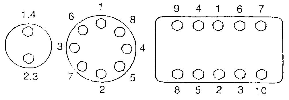
Tightening of Cap Screws and Nuts
Tighten alternately so that tightening torque can be applied evenly. The numbers in the figure below indicate the order of tightening.
JS00481A
Cap screws which have had Loctite used (white residue remains after removal) should be cleaned with light oil or suitable cleaning solvent and dried. Apply 2-3 drops of Loctite to the thread portion of the cap screw and then tighten.
Torque Table
Tighten cap screws and nuts according to the table below if there are no other special instructions.
Section 1002
Specifications Andspecialtorquesettings
Table Of Contents
WARNING: This symbol is used in this manual to indicate important safety messages. Whenever you see this symbol, carefully read the message which follows. Your safety depends on it.
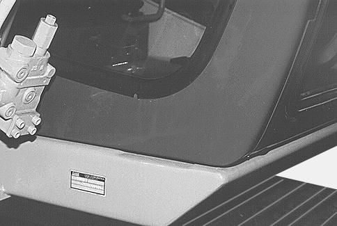
TYPE, SERIAL NUMBER AND YEAR OF MANUFACTURE OF THE MACHINE
For all part orders, request for information or assistance, always specify the type and the serial number of the machine to your CASE dealer.

Fill in the following lines with the required information: Type, serial number, year of manufacture of the machine and the serial numbers of the hydraulic and mechanical components.
Engine
(1) Type.............................................................................
(2) Serial number..............................................................
(3) Year of manufacture....................................................
Make and type..................................................................................................................
Serial number..............................................................................................................................................................
Serial numbers of the components
Travel control valve...........................................................................................................
Ingredients
The ingredients must correspond to specific characteristics for every usage.
WARNING: You must respect the operating conditions for the different ingredients.
Hydraulic fluid
The CASE hydraulic fluid is specially adapted for high pressure and CASE’s hydraulic circuit. The type of fluid to be used depends on the ambient temperature.
Temperate climates
-20°C to +40°C
Fluid type ISO VG 46
CASE reference: POHYDR
Hot climates
0°C to +60°C
Fluid type ISO VG 100
CASE reference: POHYPC
Cold climates
-40°C to +20°C
Fluid type ISO VG 22
CASE reference: POHYPF
Temperate climate biodegradable fluid: This yellow-coloured fluid is miscible with standard fluid. When introducing this fluid, it is recommended to drain the hydraulic system completely.
Fluid type: ISO VG 46
CASE reference: CASYNTH 46
These different grades of fluids must comply with the CASE specification.
Transmission assembly oil
Extreme pressure oil used for transmission assemblies in housing.
Extreme pressure oil TYPE API GL5 GRADE 80W90 and ISO VG 150
Greases
The type of grease to be used depends on the ambient temperature.
Hot and temperate climates
-20°C to +60°C
Extreme pressure EP NLGI grade 2 grease with molybdenum disulfide.
Cold climates
-40°C to +20°C
Extreme pressure EP NLGI grade 0 grease.
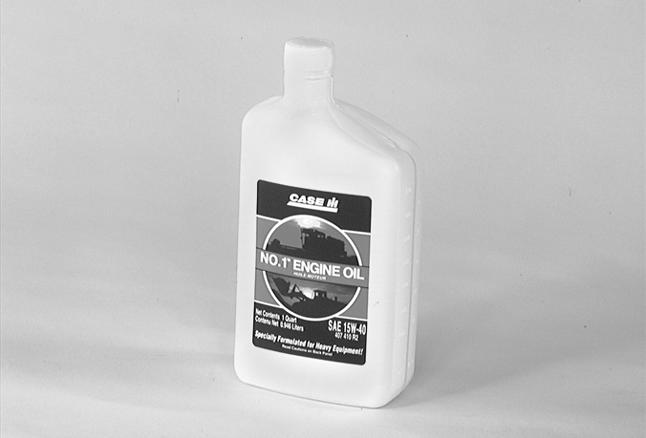
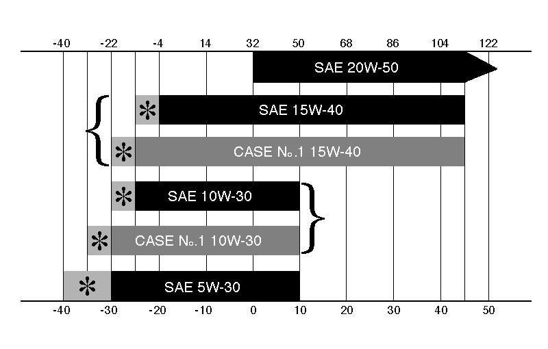
Engine oil
The CASE No.1 engine oil is recommended for your engine. This oil ensures proper lubrication of your engine for all operating conditions.

If you are unable to procure the CASE No.1 Multiperformance or Performance engine oil, use the corresponding oil from the API/CG/CF category.
NOTE: Do not put any performance additives or any other additives in the engine housing. The oil changing intervals are indicated in this manual based on tests carried out on CASE lubricants.
Viscosity of oils/Operating range of oils
Low fuel
The fuel to be used must comply with the D975 norm of the American Society for Testing and Materials (ASTM).
Use type No.2 fuel, use of other fuels can cause a loss of engine power and excessive fuel consumption.
In cold weather, it is provisionally accepted that a mixture of No.1 and No.2 fuels be used. Contact your fuel supplier.
If the temperature drops below the freezing point of the fuel (point where paraffin appears), paraffin crystals in the fuel will cause loss of engine power or starting trouble.
IMPORTANT: In cold weather, fill up the reservoir with fuel after each workday, in order to avoid the formation of condensation.
Storing fuel
Prolonged storage of fuel promotes the accumulation of foreign bodies or condensed moisture in the storage tank. Many engine failures are caused by the presence of water in fuel.
The storage tank must be placed outside and the fuel should be maintained at as low a temperature as possible. Drain the condensed moisture at regular intervals.
Antifreeze/anticorrosive
Use the antifreeze in all seasons to protect the coolant system from corrosion and to avoid any risk of freezing.
In environments with a temperature greater than -36°C, use a 50% mixture of antifreeze in an ethylene glycol base.
In environments with a temperature less than -36°C, it is recommended that you use a 40% water and 60% antifreeze mixture.
Environment
Before carrying out any maintenance operation on this machine and before throwing away the liquids or lubricants used, always think of the environment. Never throw oil or liquids on the ground and never put them in leaking containers.
Consult your local centre for ecological recycling for information on the appropriate method for disposing off these substances.
Plastic and resin parts
When cleaning plastic parts, on the console, the instrument panel, the indicator and gauges etc., do not use petrol, paraffin, paint solvents, etc. Use only water, soap and a soft cloth.
The use of petrol, paraffin, paint solvents, etc. causes discoloration, cracks or deformation of these parts.
Capacities
Specifications
These capacities are given only for information purposes. To check the fluid levels, always use the oil gauge, visual gauges or the filler cap.
Electrical system
Hydraulic system
Control valve
Five-element control valve for dipper, boom acceleration, swing, option and right travel.
Four-element control valve for dipper, bucket, boom acceleration and left travel.
Load holding relief valve for boom and dipper.
Swing
Fixed flow engine with axial pistons.
Travel
Two-speed motor with axial pistons.
Undercarriage
One-piece frame with fabricated elements.
rollers and idler wheels.
track tension.
Weight of components
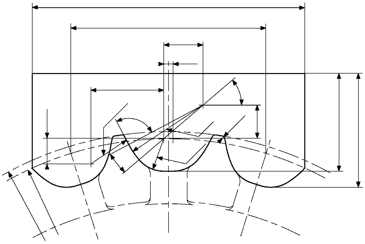
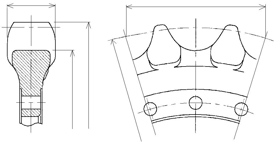
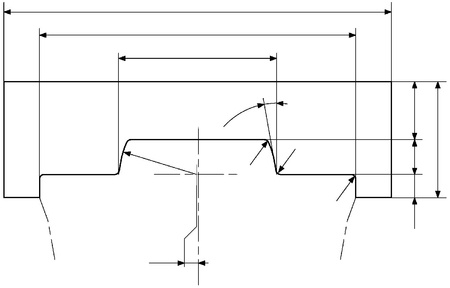
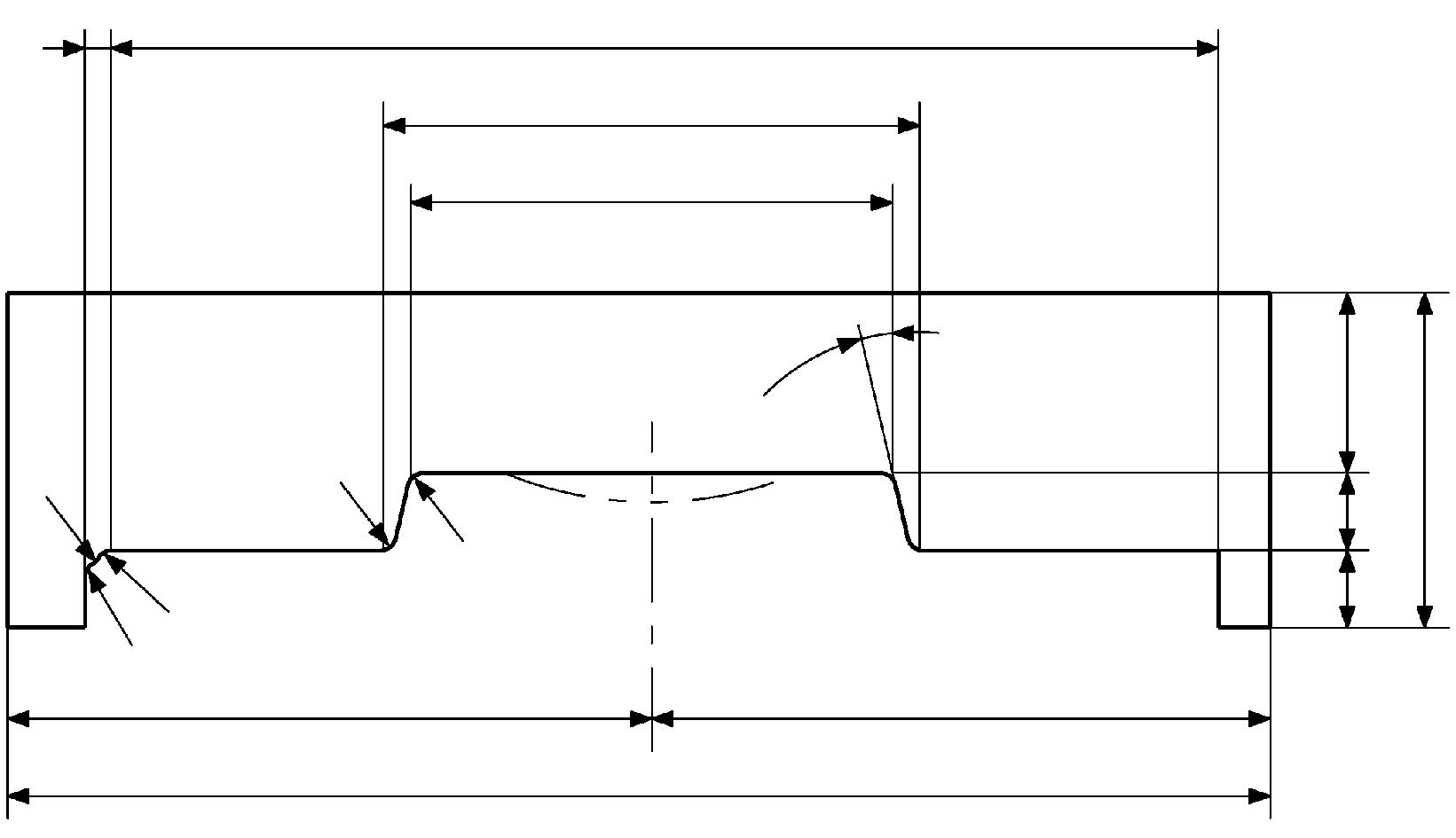
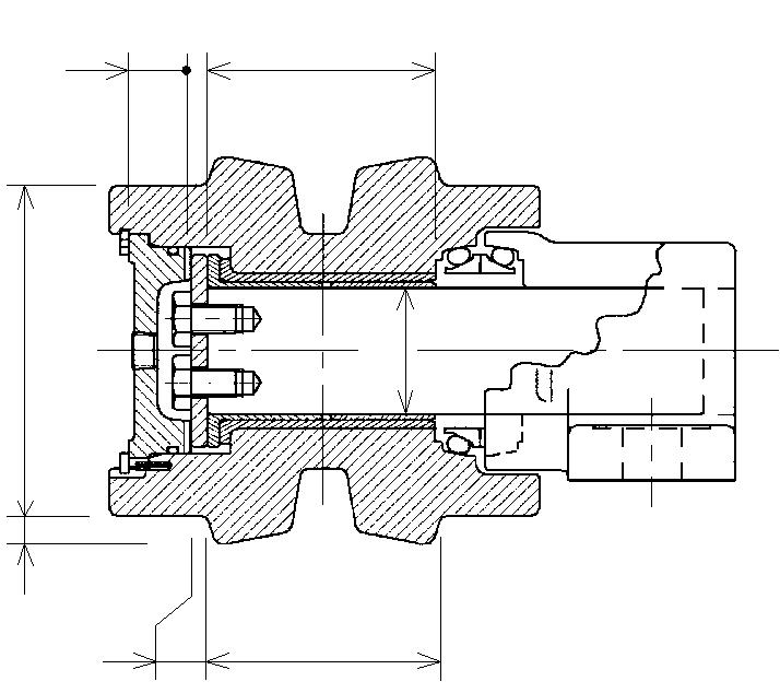
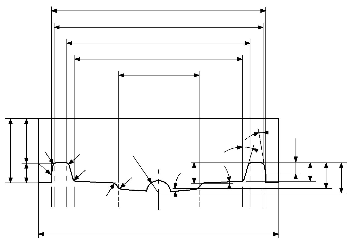
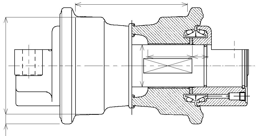
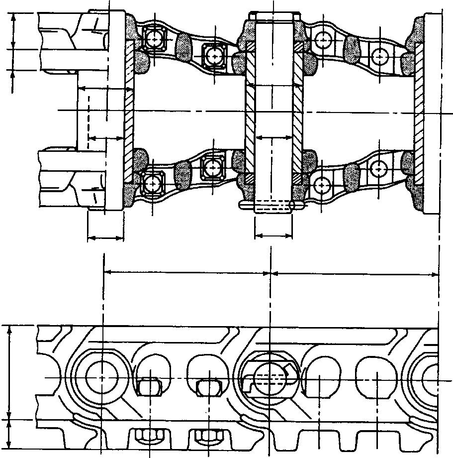
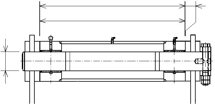
Dimensions And Wear Limit Of The Track Assembly
1002-12
Idler wheel
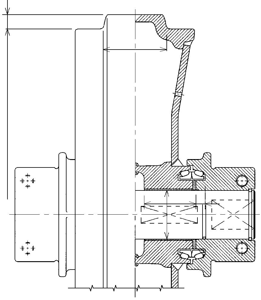
Upper roller
1002-14
Lower roller
Dimensions And Wear Limits Of Attachment Linkages
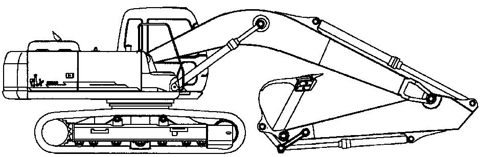
2. Boom cylinder foot/Frame
3. Boom cylinder head/Boom
4. Dipper cylinder foot/Boom
5. Boom/Dipper
6. Dipper cylinder head/Dipper

7. Bucket cylinder foot/Dipper
8. Connecting rod/Dipper
9. Compensator/Bucket
10. Connecting rod/Compensator/Bucket cylinder head
11. Dipper/Bucket
Special Torque Settings
NOTE: Use Loctite 262 or an equivalent on retaining screws of those components marked with an asterisk (*).

Suggest:
If the above button click is invalid.
Please download this document first, and then click the above link to download the complete manual.
Thank you so much for reading