11 minute read
CX330, CX330NLC and CX350 Tier 3 Crawler Excavators

NOTE: CNH Company reserves the right to make changes in the specification and design of the machine without prior notice and without incurring any obligation to modify units previously sold.
The description of the models shown in this manual has been made in accordance with the technical specifications known as of the date of design of this document.
Advertisement
Section 1001
SAFETY, GENERAL INFORMATION AND TORQUE SPECIFICATIONS
SAFETY.....................................................................................................................................................................4
STANDARD TORQUE DATA FOR CAP SCREWS AND NUTS...............................................................................6
WARNING : This symbol is used in this manual to indicate important safety messages. Whenever you see this symbol, carefully read the message that follows, as there is a risk of serious injury. !
General Information
Cleanning
Clean all metal parts except bearings, in a suitable cleaning solvent or by steam cleaning. Do not use caustic soda for steam cleaning. After cleaning, dry and put oil on all parts. Clean oil passages with compressed air. Clean bearings in a suitable cleaning solvent, dry the bearings completely and put oil on the bearings.
Inspection
Check all parts when the parts are disassembled. Replace all parts that have wear or damage. Small scoring or grooves can be removed with a hone or crocus cloth. Complete a visual inspection for indications of wear, pitting and the replacement of parts necessary to prevent early failures.
Bearings
Check bearings for easy action. If bearings have a loose fit or rough action replace the bearing. Wash bearings with a suitable cleaning solvent and permit to air dry. DO NOT DRY BEARINGS WITH COMPRESSED AIR.
Needle bearings
Before you press needle bearings in a bore always remove any metal protrusions in the bore or edge of the bore. Before you press bearings into position put petroleum jelly on the inside and outside diameter of the bearings.
Gears
Check all gears for wear and damage. Replace gears that have wear or damage.
Oil seals, O-rings and gaskets
Always install new oil seals, O-rings and gaskets. Put petroleum jelly on seals and O-rings.
Shafts
Check all shafts that have wear or damage. Check the bearing and oil seal surfaces of the shafts for damage.
Service parts
Always install genuine Case service parts. When ordering refer to the Parts Catalog for the correct part number of the genuine Case replacement items. Failures due to the use of other than genuine Case replacement parts are not covered by warranty.
Lubrication
Only use the oils and lubricants specified in the Operator’s or Service Manuals. Failures due to the use of non-specified oils and lubricants are not covered by warranty.
Safety
This symbol means ATTENTION! BECOME ALERT! YOUR SAFETY IS INVOLVED. The message that follows the symbol contains important information about safety. Carefully read the message. Make sure you fully understand the causes of possible injury or death.
To prevent injury always follow the Warning, Caution and Danger notes in this section and throughout the manual.
Put the warning tag shown below on the key for the keyswitch when servicing or repairing the machine. One warning tag is supplied with each machine. Additional tags Part Number 331-4614 are available from your service parts supplier
.
WARNING: Read the operator’s manual to familiarize yourself with the correct control functions.
WARNING: Operate the machine and equipment controls from the seat position only. Any other method could result in serious injury.
WARNING: This is a one man machine, no riders allowed. !
WARNING: Before starting engine, study Operator’s Manual safety messages. Read all safety signs on machine. Clear the area of other persons. Learn and practice safe use of controls before operating. It is your responsib ility to understand and follow manufacturers instructions on machine operation, service and to observe pertinent laws and regulations. Operator’s and Service Manuals may be obtained from your Case dealer.
WARNING: If you wear clothing that is too loose or do not use the correct safety equipment for your job, you can be injured. Always wear clothing that will not catch on objects. Extra safety equipment that can be required includes hard hat, safety shoes, ear protection, eye or face protection, heavy gloves and reflector clothing.
WARNING: When working in the area of the fan belt with the engine running, avoid loose clothing if possible, and use extreme caution.
WARNING: When doing checks and tests on the equipment hydraulics, follow the procedures as they are written. DO NOT change the procedure.
WARNING: When putting the hydraulic cylinders on this machine through the necessary cycles to check operation or to remove air from a circuit, make sure all people are out of the way.
WARNING: Use insulated gloves or mittens when working with hot parts.
WARNING: Lower all attachments to the ground or use stands to safely support the attachments before you do any maintenance or service.
WARNING: Pin sized and smaller streams of hydraulic oil under pressure can penetrate the skin and result in serious infection. If hydraulic oil under pressure does penetrate the skin, seek medical treatment immediately. Maintain all hoses and tubes in good condition. Make sure all connections are tight. Make a replacement of any tube or hose that is damaged or thought to be damaged. DO NOT use your hand to check for leaks, use a piece of cardboard or wood.
WARNING: When servicing or repairing the machine, keep the shop floor and operator’s compartment and steps free of oil, water, grease, tools, etc. Use an oil absorbing material and/or shop cloths as required. Use safe practices at all times.
WARNING: Some components of this machine are very heavy. Use suitable lifting equipment or additional help as instructed in this Service Manual.
WARNING: Engine exhaust fumes can cause death. If it is necessary to start the engine in a closed place, remove the exhaust fumes from the area with an exhaust pipe extension. Open the doors and get outside air into the area.
WARNING: When removing hardened pins such as a pivot pin, or a hardened shaft, use a soft head (brass or bronze) hammer or use a driver made from brass or bronze and a steel head hammer.
WARNING: When using a hammer to remove and install pivot pins or separate parts using compressed air or using a grinder, wear eye protection that completely encloses the eyes (approved goggles or other approved eye protectors).
WARNING: Use suitable floor (service) jacks or chain hoist to raise wheels or tracks off the floor. Always block machine in place with suitable safety stands.
WARNING: When the battery electrolyte is frozen, the battery can explode if (1), you try to charge the battery, or (2), you try to jump start and run the engine. To prevent the battery electrolyte from freezing, try to keep the battery at full charge. If you do not follow these instructions, you or others in the area can be injured.
Standard Torque Data For Cap Screws And Nuts
Tightening of cap screws, nuts
Tighten alternately so that tightening torque can be applied evenly. The numbers in the figure below indicate the order of tightening.
Cap screws which have had Loctite used (white residue remains after removal) should be cleaned with loght oil or suitable cleaning solvent and dried. Apply 2-3 drops of Loctite to the thread portion of the cap screw and then tighten.
Torque table
Tighten cap screws and nuts according to the table below if there are no other special instructions.
Cap Screw Name Size (Size)M6M8M10M12M14M16M18M20
Section 1002
Specifications Andspecialtorquesettings
Table Of Contents
WARNING: This symbol is used in this manual to indicate important safety messages. Whenever you see this symbol, carefully read the message which follows. Your safety depends on it.
TYPE, SERIAL NUMBER ANDYEAR OFMANUFACTUREOF THEMACHINE
For all part orders, request for information or assistance, always specify the type and the serial number of the machine to your Case dealer.
Fill in the following lines with the required information: Type, serial number, year of manufacture of the machine and the serial numbers of the hydraulic and mechanical components.

Serial numbers of the components
Fluids And Lubricants
Lubricants must have the correct properties for each application.
WARNING: The conditions of use for individual fluids and lubricants must be respected
Hydraulic fluid
CASE/AKCELA hydraulic fluid is specially designed for high pressure applications and for the CASE hydraulic system. The type of fluid to be used depends on the ambient temperature.
Temperate climates: -20°C to +40°C (-4° to 104° F)
CASE/AKCELA: HYDRAULIC EXCAVATOR FLUID (MS 1230. ISO VG 46. DIN 51524 PART 2 HV)
Hot climates: 0°C to +50°C (32° to 122° F)
CASE/AKCELA: AW HYDRAULIC FLUID 68 HV (MS 1216. ISO VG 68. DIN 51524 PART 3 CATEGORY HVLP)
Cold climates: -25°C to +20°C (-13° to 68° F)
CASE/AKCELA: AW HYDRAULIC FLUID 32 (MS 1216. ISO VG 32. DIN 51524 PART 2)
Biodegradable fluid: -30°C to +40°C (-22° to 104° F)
This yellow-colored fluid is miscible with standard fluid. If used to change standard fluid, it is advised to drain the circuit completely before refilling with this fluid.
CASE/AKCELA: HYDRAULIC EXCAVATOR FLUID BIO (MS 1230. ISO VG 46. DIN 51524 PART 2 HV)
Transmission component oil
Extreme pressure oil used for enclosed transmission components.
CASE/AKCELA: GEAR 135H EP (SAE 80W-90. API GL 5. MIL-L-2105 D. MS 1316. ZFTE-ML 05A)
Grease
CASE/AKCELA: MOLY GREASE 251H EP-M (251H EP-M NLGI 2)
"Extreme Pressure" multipurpose grease with lithium soap and molybdenum disulphide.
CASE/AKCELA: MULTIPURPOSE GREASE 251H EP (251H EP. NLGI 2)
"Extreme Pressure" multipurpose grease with lithium soap and calcium.
CASE/AKCELA: PREMIUM GREASE EP2 (NLGI 2)
"Extreme Pressure" multipurpose grease with lithium soap.
Hydraulic breakers
CASE/AKCELA: MULTIPURPOSE GREASE 251H EP (NLGI 2).
Engine Oil
THE CASE/AKCELA No.1 engine oil is recommended for your engine. This oil ensures proper lubrication of your engine for all operating conditions. If you are unable to procure the CASE No.1 Multiperformance or Performance engine oil, use the corresponding oil from the API/CG/CF category.
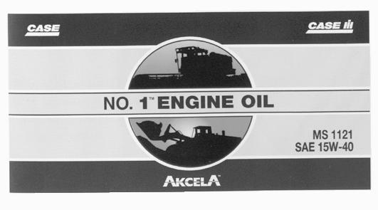
NOTE: Do not put any Performance Additives or any other additives in the engine housing. The oil changing intervals are indicated in the Operator’s manual based on tests carried out on CASE lubricants.
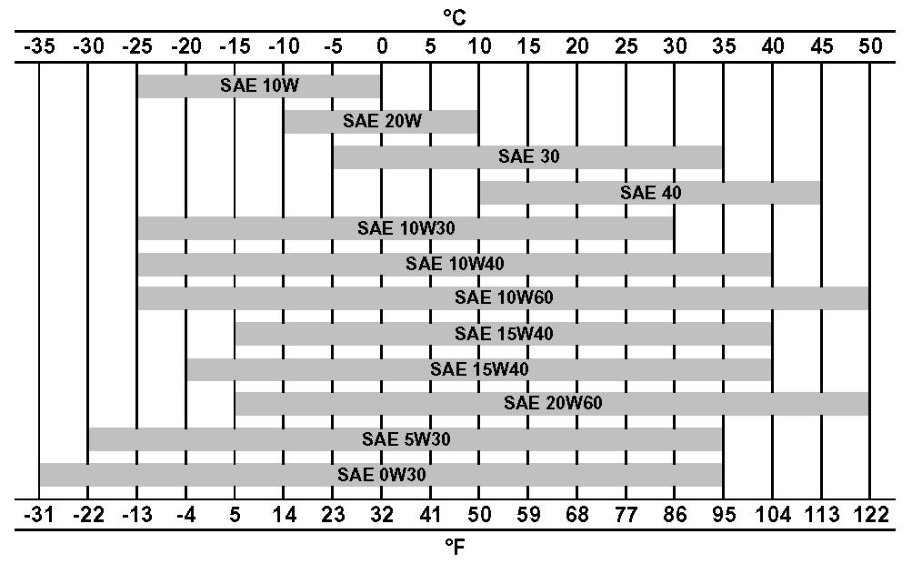
Oil viscosity / Oil range
Fuel
Use fuel which is to ASTM (American Society for Testing and Materials) D975 standard.
Use grade No.2-D fuel. The use of other types of fuel can result in a loss of power of the engine and may cause high fuel consumption.
In cold weather (below -7°C), it is provisionally approved to use a mixture of fuels No.1-D and No.2-D.
If the temperature falls below the fuel cloud point (point at which wax begins to form) the wax crystals will cause power loss or will prevent the engine from starting.
Required conditions for diesel fuel
The following specific conditions are required for diesel fuel:
- Must be free from minute dust particles.
- Must have adequate viscosity.
- Must have high cetane value.
- Must have high fluidity at low temperature.
- Must have low sulphur content.
- Must have little residual carbon.
Diesel fuel recommendation
- JIS (Japanese Industrial Standard) : No.2
- DIN (Deutsche Industrie Normen) : DIN 51601
- SAE (Society of Automotive Engineers) Based on SAE-J-313C: No.2-D
- BS (British Standard) Based on BS/2869-1970: Class A-1
IMPORTANT : If fuel other than the specified one is used, engine operation will be impaired.
Using fuels other than those recommended can damage the fuel injection pump, the injector and other parts of the fuel supply system and the engine. CASE disowns any responsibility concerning this kind of damage, which is not covered by the guarantee. To avoid any damage to the engine fuel supply system, you are recommended to take the following safety messages into account:
Some fuel suppliers mix used engine oil with diesel fuel. Certain manufacturers of large engines allow them to do this. However, for your engine, do not use diesel fuel contaminated by engine oil. In addition to damaging the engine, this fuel can actually adversely affect the correct purification of exhaust gases. Before using any diesel fuel, ask the supplier if this fuel has been mixed with engine oil.
IMPORTANT : For use of the correct fuel additives, consult your oil or lubrication supplier. Do not inject fuel oil or gasoline, both fuels can damage the engine.
IMPORTANT : In cold weather, fill the fuel tank at the end of the day's work, in order to prevent the formation of condensation.
Fuel storage
Long storage can lead to the accumulation of impurities and condensation in the fuel. Engine trouble can often be traced to the presence of water in the fuel.
The storage tank must be placed outside and the temperature of the fuel should be kept as low as possible. Drain off water and impurities regularly.
Anti-freeze/Anti-corrosion
Use anti-freeze in all seasons to protect the cooling system from corrosion and all risk of freezing.
CASE/AKCELA: PREMIUM ANTI-FREEZE (MS 1710)
For areas where the temperature goes down to -38°C, mix 50/50 with water.
IMPORTANT : Do not mix products of a different origin or brand. The same product must be used when topping up the system.
Environment
Before carrying out any maintenance operation on this machine and before disposing of used fluids or lubricants, always think of the environment. Never throw oil or fluid on the ground and never place it in leaking receptacles. Contact your local ecological recycling centre to obtain information on the correct method of disposing of these lubricants.
Plastic and resin parts
When cleaning plastic parts, the console, the instrument panel, the indicators etc... avoid using petrol, kerosene, paint solvents etc... Use only water, soap and a soft cloth.
The use of petrol, kerosene, paint solvents etc... causes discoloration, cracks or deformation of these parts.
Specifications
Complete machine dimensions
Body Dimensions
Type: 4-cycle, water-cooled, overhead camshaft, common rail injection (electric control), with air-cooling type inter-cooler turbo with air-cooling.
Cooling system
1002-10
Operating devices
Operator's seat
Location; left side
Structure; low frequency air suspension with helical springs and double acting hydraulic damper. Cab
Smooth and round shape design cab, fabricated by press work Safety glass for all windows.
Levers and pedals
For travel use; levers and pedals (hydraulic pilot type) (2)
For operating machine use; levers (hydraulic pilot type) (2)
Instruments and switches
Work mode switchover; 4 modes (heavy digging, standard, finishing and auto)
Travel speed switchover; Low Speed / High Speed panel switch
One-touch idle; Knob switch type
Monitor device
Machine status display (full-dot liquid crystal)
Travel speed selection status; Low Speed / High Speed
Work mode selection status; H/S/L/A
Auto idle selection status; ON/OFF
Instruments (full-dot liquid crystal, except for hour meter)
Fuel gauge; bar graph indicator
Engine coolant temperature gauge; bar graph indicator
Hydraulic oil temperature gauge; bar graph indicator
Hour meter; digital type
Over heat*Battery charge*Faulty electrical system*
Refill fuel*Engine oil pressure* Refill coolant*
Engine preheatAuto warm-upAir cleaner*
IdlingService interval
Machine Status and Warning Alarms (full-dot liquid crystal and warning tone) *Items have a warning alarm Lighting
Horn; electric horn (2)
Other
Wiper with intermittent function (1)
Window washer fluid (1)
Air conditioner (1)
Rear view mirror (right-hand side) (1)
Hydraulic system
Hydraulic pump drive system, directly coupled to the engine (no transmission)
Model; 4-spool section: integrated (1) or 5-spool section: integrated (1) hydraulic pilot method: travel, swing and operating machine
Functions
Straight travel circuit
Boom UP / 2-speed internal confluence for Arm
Boom/arm load holding circuit
Boom down regenerative circuit
Arm IN forced regenerative circuit
Variable throtlle valve in parallel circuit arm
Swing priority variable throttle valve
Preliminary 2-speed confluence
Hydraulic Cylinders
Digging force (New JIS)
Swing unit
Swing circle; swing bearing type (with internal gears)
(1); fixed displacement piston motor with parking brake and reversal prevention mechanical lock (swing lock switch linkage type)
Travel lower body lock (travel lever linkage type) Track
1002-14
Work Unit
Model;
Reference Values
Numerical values for performance may change without notice due to product improvement.
2Pressure of each part (MPa)
3 Natural lowering level of each cylinder (mm)
4 Operational speed of each cylinder
8 Number of drive sprocket revolutions (sec/10 revolutions)
9Amount of turntable bearing shift (mm)
10 Amount of shoe tension ranging from the side frame bottom to shoe surface (mm) 340
Major component weight
Component Weight
Weight information is approximate
Other component weight
Dimensions And Wear Limit Of The Track Assembly
Idler wheel
Upper roller
Lower roller Dimensions
2. Boom cylinder foot/Frame
3. Boom cylinder head/Boom
Suggest:
If the above button click is invalid.
Please download this document first, and then click the above link to download the complete manual.
Thank you so much for reading