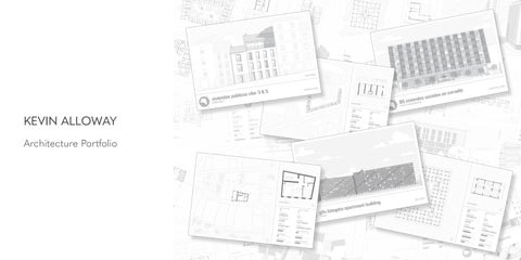
KEVIN ALLOWAY Architecture Portfolio
1
FULL PORTFOLIO AVAILABLE HERE
ACADEMIC PROJECTS THEN | NOW | LATER
6
(UN)DEVELOPABLE
24
SPINE
34
ZIG-ZAG
42
YIMBY
58
PROFESSIONAL PROJECTS HOME RENOVATION
64
MUDROOM CONCEPT
66
PROPOSED ADDITION
68
BEACH HOUSE RENOVATION
70
RENDERINGS
72
PERSONAL PROJECTS ARTWORK
76
ACADEMIC
THEN | NOW | LATER COMPREHENSIVE DESIGN STUDIO SPRING 2023 Comprehensive Design Studio, in conjunction with corequisite Integrated Building Systems, is primarily concerned with moving beyond purely aesthetic design proposals and instead considering the multitude of systems that go into bringing a building into reality, like structure, landscaping, MEP, and code. Working in pairs, students were first tasked with designing a structural module that could adapt to a variety of unknown sites and situations. Later in the semester, the location was revealed - a former B&M Beans factory in Portland, Maine and students were asked to integrate that structural system into an overall site strategy. Next, program was announced; students were to develop a branch campus for Northeastern Univeristy’s STEM programs. Lastly, students had to take their original designs and reimagine them in the distant, unknown future. Our building is an experiment in longevity, perseverance, and adaptability. A series of wide, stepped, crescent terraces, supported by a sea of columns, hug the historic B&M building. A large atrium is carved out where the two buildings meet, helping to bring daylight into the interior, but also highlighting the differences between the two structures. Similar carving moves are made elsewhere around the building’s facade, to help break up the massing. For the next few decades, we’ve crafted a program in-line with Northeastern’s vision; a collection of laboratory, educational, assembly, and office spaces working together as a hub of innovation. Looking further into the future, we’ve leaned into a more fantastical, extreme scenario to test the limits of our system, turning the building into a clean energy power plant and food production facility. 6
*Design was developed in partnership with Yue Xiao, but work herein is my own.
7
E
tin s i x
it gS
an e Pl
Pr o
Si te an Pl
8
lan ite P
2 10 0
5S
ed
02 d2 se po
Propo s
DEVELOPMENT The semester began with developing a utilitarian, adaptable structural system. Next, the location was introduced and a site strategy developed. Lastly, programs were integrated into the design, with an emphasis on flexability and versatility.
TWO-WAY SLAB
AXIAL SITE STRATEGY
BALANCED SPECIAL MOMENTS
Concrete is robust, durable, and plastic, and can therefore persevere over time while going beyond a standard grid layout.
Landscaped “Green” axes connect adjacent neighborhoods to the water through the site, and determine building massing and locations.
Program balanced unique, and special moments to endear the building to its users while other, more generic components ensured utility and flexibility.
Existing Building
Open Interior
Initial New Massing
Wrap Facade
Shape to Site
Carve Massing
Carve Facade
Proposal 9
2025 INITIAL PROPOSAL The B&M buildling’s lower FTF heights lend themselves well to office, work, and meeting spaces. The taller ceilings in the new addition accomodate a wider variety of programs, including labs and classrooms. The floorplates of the two buildings align on the first and fourth floors, but in between, the open central atrium highlights the jusxtaposition of the old and the new, and a series of ramps, landings, and stairs stitch the two buildings together. The basement, only under the northern half of the building to protect equipment from enroaching tides, is designed to flood.
3.0
1.
2.5 2.
1.5
10
4.
1.0
6.
8
0.5
Floors 0 - 2 include offices, classrooms, labs, collaborative work spaces, social programming, and roof gardens. The third floor primarily contains the internal and external mechanical penthouses.
3.
2.0
0.0
9.
-0.5
5.
5’
30’
DYNAMIC FACADE 50’
15’
1. Covered Patio 2. Bookstore 3. Cafe 4. Faculty Offices 5. Loading Dock 6. Atrium 7. Classroom 8. Classroom
9. Classroom 10. Dry Lab 11. Dry Lab 12. Lab Storage 13. Classroom 14. Write-up 15. Wet Lab 16. Write-up 17. Wet Lab
The slatted timber facade that wraps the building adapts to each orientation. On the southern side, it includes an occupiable, operable double-skinned facade for natural climate control in both the winter and summer (depicted below). On the eastern and western facades, the timber members deepen to act as vertical shading devices. On the northern face, they are shallower and more widely spaced to facilitate daylighting.
Extensive Roof Garden Operable DoubleSkinned Facade
7.
10.
14.
Angled Finished Ceiling for Daylighting
11.
8. 15.
Occupiable Balcony
12.
16.
Shading Devices
MEP Space 13. 17.
Perimeter Heating
Foundation Piles 11
NORTHERN ELEVATION - 7:00 AM
EASTERN ELEVATION - 11:00 AM
12
SOUTHERN ELEVATION - 3:00 PM
WESTERN ELEVATION - 7:00 PM
13
14
15
1.
The shoreline is filled with rocks and native plants to not only provide habitat, but to also mitigate erosion and and help with flood control.
2.
A small spur of road is continued along shore, reaching just 150’, which is the maximum dead-end distance allowed for fire truck access
3.
A large staircase and ramp system connects the waterfront to the main atrium of the building, continuing the north-south axis defined in the site plan. The elevation change also serves to protect against flooding.
4. The loading dock is tucked into the basement of the B&M building and hidden from the rest of the site with landscaping 5.
The double-skinned facade on the southern side of the building is carved away in portions to gesture at the carvings happening behind them on the interior of the building.
6. Where it is not carved away, the double-skinned facade not only helps trap air and keep the building warm in the winter, but is occupiable and has operable windows so it can be enjoyed in the summer months as well.
7.
8.
9.
The top floor contains the building’s mechanical systems. Given the wide footprint and large open space in the center, the building has two separate ventilation systems, one for the north side and one for the south, which allows more efficient air flow as well as smaller ductwork. Finished ceiling panels are angled away from exterior walls, making the building appear less dense from the outside but also allowing more daylight to penetrate the interior. Egress stairs are contained within concrete cores, which act as shear walls and provide lateral stability to the column and post-tensioned slab system.
10. 16’ floor-to-floor heights and no deep beams or girders allow for ample space to run MEP in hallways and above program spaces.
12. Drains on the roof collect rain w stored as graywater in the basem
13. The core, defining moment of th atrium, carved out between the and used as a space of congrega socialization. 14. Graywater collection tanks (see
15. Above the atrium is a large skyli to better penetrate into the dee third floor, near the glass roof, a mechanical equipment, to allow collected and recycled.
11. Two smaller cores flank the atrium and provide spaces for restrooms as well as additional opportunities for vertical plenums. Given the choice to use post-tensioned slabs, which can be hard to cut apart later on, we opted to overly-carve out the floor plate now and give plenty of space to run MEP vertically.
7.
5. 8.
4.
6.
1. 3.
2.
16
water, which is treated and ment (see note 14).
he project is the central e new and old buildings ation, circulation, and
16. Since the mechanical systems are located primarily within the top floor, large portions of the roof are open and available for solar panels. 17. Given Portland’s cold winters, only the equipment that needs to be outside is outside. This includes chillers and exhaust fans.
note 12)
ight, which allows daylight ep floor plates. On the are louvers into the w rising hot air to be
17.
15. 16. 12.
22.
18. 13.
21.
10. 19.
11. 14.
9.
20.
18. Skylights following the curves of the building cut into the floor plates to bring natural light deeper into the interior halls.
the shore, and all equipment are elevated on skids, so that in the case of flooding, they remain protected.
19. Active chilled beams are the primary HVAC system used in the building given their efficiency and the fact that they don’t need as large a duct as traditional ventilation systems.
21. Extensive roof gardens sweep across the curving terraces of the building, helping to keep interiors cooler in the summer, decrease site water runoff, and provide habitat to local insects and birds.
20. Some of the mechanical equipment, like water and sewer, are located in the basement. Because of the project’s proximity to the floodplain, the basement is only located on the side of the building furthest away from
22. Shading devices on the eastern facade continue the same language as decorative elements on the southern one ,but here they are deeper and more vertically-oriented, to help reduce morning sun glare. 17
2100 A REIMAGINED FUTURE This future scenario imagines a world, around 2100, with a greater reliance on renewable energy, higher sea levels, continued inequitable access to fresh food, and freshwater scarcity. Portland’s energy production, storage, and transmittal are dispersed accross as series of microgrids and food production is localized. Northeastern’s building takes on a new life, as what is essentially a giant, rechargable battery and greenhouse. Water, now inundating the ground floor of the B&M building during high tide is pumped, filtered and electrolyzed using renewable energy in times when supply exceeds demand. The resulting hydrogen is used to power fuel cells sitting in the eastern poriton of the building when the community’s energy demands exceed what renewables can supply. The other byproducts of the fuel cells, heat and fresh water, are used to run a hydroponic greenhouse operation in what was previously the central atrium.
18
1.
2.
3.
9.
8.
4.
6.
7.
5.
10.
5’
30’ 15’
1. Loading Dock 2. Storage 3. Electrolysis 4. Filtration 5. Water Collection
50’
A nightime view from the nearby overpass.
6. Irrigation Tanks 7. Greenhouse 8. Greenhouse 9. Fuel Cells 10. Greenhouse 11. Greenhouse
Inside a growhouse, looking out into the central atrium.
.
11.
19
20
In the eastern (left) half of the building, fuel cells help balance Portland’s energy needs, and are fed with hydrogen from the electrolysis plant in the western, original B&M building (right). The plant utilizies higher sea levels to draw water in from the bay during high tides. In the central and southern portion, a series of greenhouses make use of the excess heat and water produced by the building’s other functions, and assists with Portland’s food security.
21
(UN)DEVELOPABLE OPTION STUDIO: PUBLIC LAND FOR PUBLIC GOOD FALL 2022 The Public Land for Public Good studio focuses on increasing community resilience through unique, tailored interventions on small, Boston-owned lots that have been labeled “undevelopable” by the city. The first half of the semester focused on research, and the second focused on design. Students explored a range of topics, including food insecurity, arts-access, education, transportation, and small businesses. (UN)DEVELOPABLE focsuses on housing, and specifically homeownership and its relation to identity, place--making, and economic ownership. Although housing is an outcome of this project, its main goal is to foster ownership, both in the literal and figurative senses. Ownership, representation, and presence are key variables in a community’s structural system. Unless all members have a stake in the system, there is no chance of the community flourishing. How can you better your life if you have no control over the factors that influence it? Why should you care what happens to your neighborhood if it doesn’t recognize you? Our local points of interest and social interaction have to reflect our unique needs and preferences, and they have to be easily accessible. We should own our own residential spaces, or at the very least, pay rent to a landlord who we know and who is a real person in the community. In this project, a group of efficient, yet dignified residences - designed for a range of individuals and lifestyles - are integrated into an established neighborhood and grounded to the community with a dedicated space for locally-owned commercial enterprises.
24
This collection of Boston’s “undevelopable” sites is located on the Roxbury / Dorchester border of the city, near John Winthrop Elementary. Each student was assigned a site and developed a proposal to address an unmet need community need, which was identified during the initial research phase of the semester.
These programs included housing, small-business incubators, markets, transportation hubs, artist studios, libraries, food halls, etc...
This specific proposal is a mixed-use residential and commercial project that aims to supply “Missing Middle” housing but also opportunities to boost the local economy via a dedicated space on the ground floor for local entrepreneurs to set up shop.
25
COFFEE SHOP
10’
1’ 5’
UNIT 3
GROUND FLOOR
Coffee Shop: 700 sf Unit 1 (Accessible): 870 sf
26
f
SECOND FLOOR Unit 2: 870 sf Unit 3: 750 sf
27
UNIT 5
10’
1’ 5’
UNIT 4
THIRD FLOOR Unit 4: 1,680 sf (Level 1 Unit 5: 1,460 sf (Level 1 28
FOURTH FLOOR - 870 sf) - 750 sf)
Unit 4: 1,680 sf (Level 2 - 800 sf) Unit 5: 1,460 sf (level 2 - 710 sf) 29
UNIT 2
UNIT 3
10’
1’
30
5’
UNIT 4
UNIT 5
UNIT 2
UNIT 3
UNIT 1
COFFEE SHOP
31
SPINE
EXISTING CONDITIONS & CONTEXT
DESIGN TACTICS FALL 2022 SPINE transforms the existing Stony Brook Sewer Easement into a meaningful space of relaxation, contemplation, and ecosystem rehabilitation. The existing site onsits of a wide, direct asphalt path from Fenway to Hemmenway Street. Two rows of oak trees flank the path along with a few street lights. The southern side of the site is flanked by a Northeastern University academic building, and the northern side by apartments. Underneath the site, unseen, is a culverted river that eventually empties in the Muddry River, just across the street. A primary purpose of the new design is to connect the Northeastern Campus to the Back Bay Fens park. To do this, it’s essential that the park become a special place in its own right, and not a mere space of transition like it is today. Because it is separated from the university and the park by roads, it is an island of its own and therefore has the opportunity to grow into something special and unique.The park achieves this balance of unique identity and relation to its neighboring programs through three primary tactics: hydrology, vegetation, and circulation. A series of dry-wells are dug to assist in storm water management and water filtration, while also acting as a nod to the culverted river that runs underneath. In each of these basins, an island filled with native plants rises up, adding to the forest-like atmosphere already created by the towering pin oaks. Circular boardwalks with benches and the occasional overhang for shelter surround these islands, allowing for slow meandering and places of rest. Finally, tying each space together and again appealing to the idea of a miniature forest, is a spine of slender wood columns that snakes through the site and lends the park its name. 34
PHRAG
DAYLIGHTING
DREDGING
The Muddy River is in the middle of a multi-year restoration project, which includes operations such as daylighting, dredging, and removal of invasive phragmites. The goals of this project are not only aesthetic, but also functional. Once complete, the Muddy River and Emerald Necklace should better be able to filter pollutants, assist in storm water management, and provide habitat for local flora and fauna.
A MORE ACTIVE REDESIGN The goals and tactics of the broader park restoration efforts are mirrored in the design of this new park in the Stony Brook Sewer Easement.
GMITES
CIRCULATION
STONY BROOK SEWER EASEMENT
The linear path is shifted north between the buildings and first row of trees. A second, slower circulation path consists of a series of four circular boardwalks that surround the wells and forested islands.
VEGETATION
He m
enw
ay
The existing pin oaks are untouched and are supplemented by other native, low-maintenance trees, bushes, and grasses to create a lush park in the middle of the city.
HYDROLOGY Dry river beds are dug along the center of the park. The approximately 8,000 cubic feet of excavated earth is redistributed around the site, some into islands in the middle of the river beds, and some along the edges, to funnel water runoff into the center wells.
35
A longitudinal section detailing different shading conditions throughout a summer day
6:00 AM
36
10:00 AM
2:00 PM
6:00 PM
A birds-eye section perspective detailing a typical boardwalk ring with constructed components, natural systems, and program pieces.
37
SEASONAL PERSPECTIVES Rendered perspectives from various points throughout the park at different times of year. The intervention turns the previous underutilized space into an enjoyable, occupiable area in all four seasons.
38
39
ZIG-ZAG
N
Po int C Fo rt
ZIG-ZAG is a proposed mixeduse project in Boston’s Fort Point neighborhood consisting of a library in the southeast corner and a community athletic center in the northwest corner. Connecting the two projects is a zig-zagging spine, which dances across the site and coalesces at either end to form the aforementioned programs.
ha nn el
GRADUATE SKILLS STUDIO SPRING 2022
The spine not only ties the site together and connects the recently redeveloped waterfront with the historic neighborhood, but also provides a playful folly for visitors to interact with as they travel throughout the parking-lotturned-park. The zig zag itself is made out of modular prefabricated concrete elements, which can be arranged in a variety of ways, and readily assembled on site.
Ne c
Co
urt
AS
tre et
co
The project is imagined in two phases, the first of which includes the library, and the second of which includes the athletic center.
42
Bin
for dS
tre
et
DIAGRAMMATIC MODELS
This project drew inspiration from an early diagrammatic model.
It consists of a series of folded panels, each progressively thicker than the previous one.
Each panel also contains a different pattern of arches at various scales.
The model is folded in a variety of ways to create interesting moments between the angles and arches.
SITE & NARRATIVE
Acknowledge I-95 running below and across the site.
Connect the waterfront to the adjacent neighborhood.
Slow down circulation across the site.
Create open and closed spaces throughout.
Strategically dance across the subterranean highway.
Final Zig-Zag, expanding and contracting across the site.
FORM & ORGANIZATION
The basic building block is a 12'x12'x12' cube.
It borrows the arch from the Each block is made of adjacent historical buildings. prefabricated components.
Modules can be arrayed linearly or stacked vertically.
Larger modules retain the same original proportions. 43
LIBRARY
REPEATED MODULE
ZIG-ZAG, PHASE 1 The library is carved out of overlapping lengths of the zig zag and is about the experience of traveling across and through a series of arches. The library is more than just a repository for books, but also houses dedicated offices and meeting spaces for community organizations.
PIVOTED BRANCHES
The building starts with a repeated series of the standard 12’x’12’ module of prefabricated arches. They are arranged horizontally and stacked vertically. The blocks are rotated on alternating ends to achieve the zig-zag pattern. The angles of the rotation are informed by the available locations for footings given the highway that runs under the site. The 12’ arch spacing is maintained, creating a variety of unique openings and spaces as modules overlap. Some arches are combined into larger openings, but the same underlying 12’ pattern remains unbroken. The experience becomes one traveling perpendicularly through a series of arches, and of opening and closing spaces. The exception is the 4th floor, where the external path along the zig zag continues into the library, and the experience is flipped to one of travelling along the spine. 44
AGGREGATED SYSTEM
LATERAL EXPERIENCE
45
1. 2. 3. 4. 5. 6. 7. 8. 9.
Bike Storage Loading Dock and Trash Houseless Re-entry and Career Services Circulation: Special Re-shelving Front Desk Circulation: AV / Digital Circulation: Periodicals Staff Lounge
1. 5.
2.
3.
6.
4.
9.
8.
7.
SECOND
GROUND
BASEMENT
T
Primary Program BOH, MEP, Services Vertical Circulation 10’
46
10’
10’
1. 2. 3. 4.
Outdoor Ambulatory Cafe Circulation: Non-Fiction Reading Room
10’ 1.
N
2.
4.
3.
THIRD
FOURTH
10’
FIFTH
10’
ROOF
10’
10’
47
S
Third floor corridor
48
Second floor atrium
Reading room entrance
Reading room mezzanine
49
REPEATED MODULE
ATHLETIC CENTER ZIG-ZAG, PHASE 2 The athletic center forms at the other end of the site, and starts with the same language of the library, but offers a reinterpretation. Just as the library is more than just a library, the athletic center also aims to offer more to the community by providing spaces for childcare services, as well as a full floor of residential units.
PIVOTED BRANCHES
The athletic center also starts with the standard 12’x’12’ module, continuing on from the library across the site. The zig zag is opened up, emphasizing the in-between spaces and allowing room for program to infill. This provides built-in opportunities for phasing, allowing development timelines to better aling with budgets. The 12’ spacing is still maintained, but this time the zig zag path never overlaps. Arch sizes, still in 12’ intervals, corelate to the size of the spaces and programs they overlook. The experience of the athletic center is one of traveling horizontally along the zig zag, with vertical circulation and MEP running through the corners, and programs nestled in the larger open spaces between each branch.
50
AGGREGATED SYSTEM
LONGITUDINAL EXPERIENCE
SOUTH
HERN BLOCK
NORTHERN BLOCK
51
THIRD FLOOR The third floor contains the primary cardio area, which looks out across the four-story highdive space. Also on this floor are fitness studios (left), changing rooms (center), and boxing equipment on mezzanines above the basketball space (right).
GROUND
52
N 10’
SECOND
THIRD
FOURTH FLOOR Here, an indoor track breaks up the usual circulation pattern, cutting across the zig-zag, but still fitting neatly within the pattern of arches of the 12' module. This floor also contains additional cardio equipment, locker rooms, a yoga studio, and a weight room.
FOURTH
N 10’
FIFTH
SIXTH
53
A view from outside the thifd floor locker rooms, looking across the central atrium.
54
A perspective along the fourht floor indoor track, with yoga studios on the right, and the central atrium on the left.
55
YIMBY THESIS STUDIO FALL 2023 - SPRING 2024 YIMBY, short for “Yes in My Back Yard”, is a thesis proposal situated within the third-year research studio Public Housing: Confonting Apathy through Image and Influence. In this year-long studio, students have been tasked with taking a stance in the public housing debate, and proposing a design solution aligned with that stance. The final deliverable for this studio is not just a housing design, but a media campaign or representational strategy that endears that proposal to the public; to intentionally and judiciously use representation as a tool to change public perception around public, affordable, and low-income housing. The first half of the studio, the fall 2023 semester, was dedicated to research and developing a thesis, and the spring 2024 semester is focused on bringing that thesis to fruitition. In YIMBY, I start with the stance that public housing has not worked in the United States, it’s not going to work, and if it were to ever become a viable solution, it is not the architect’s job to so drastically change the US’ economic, political, and social systems. Arguable, architects have historically had very little power in shaping the vast majority of our residential built environment, but there are opportunities to influence financial and regulatory systems with design. With this mindset, YIMBY seeks to promote the “Missing Middle” housing typology as a sustainable, community-centric method of increasing housing supply and therefore also addressing affordability. The final product for this thesis will likely be a book or social media campaign that inspires conversation to encourage neighborhoods in urban peripheries to embrace well-designed, infill housing in their midst.
58
Single Family Lot: 9,000 sf Setback: 35’, 7’ 15’ FAR: 0.50
Expanding Architecture’s Role Architects traditionally have had very little power to majorily shape the residential built environment, but that can change. How can architects start conversations about changing zoning laws, allowing for densification, combating NIMBY-ism, and promoting non-developer-led design? How can we create a dialogue that gets developers, city planners, community members, policy makers, and architects all on the same page and united in their efforts? What can you build on a typical single-family lot as-of-right? How many people can that house? How does it fit in with the neighborhood? What happens if you switch to a multi-family designation? What if you change the FAR? Decrease the setbacks? Increase the height limit? Remove parking requirements? Allow more ADUs? In all these situations, with only minor changes to existing code, is there a way to increase housing supply, and therefore decrease housing costs, while simultaneously not compromising the character of the neighborhoods?
Multi-Family, Revised FAR
Multi-Family Lot: 2,000 sf Setback: 10’ FAR: 0.348
Lot: 2,000 sf Setback: 10’ FAR: 0.50
Catalogue of Design Implications of Specific Code Revisions
Single Family
Multifamily
FAR
Setbacks
Height
Parking
Egress
ADUs 59
Representation as an Intentional Tool How we communicate our ideas as architects matters.
The style, methods, and tools we employ to draw proposals all impact how our work is perceived just as much as the design itself. With that in mind, how can we inentionally leverage representation to bolster our arguments? Can we lean into the abstract and fantastical to spark imagination, and therefore intrigue, better than attempts at photorealism? Does a rendering imitating a 3D printed and chipboard model, or one mimicking a plastic doll house appeal to our psychological side and therefore make us more interested in, and accepting of, what these designs propose?
60
Ongoing Questions This project is just in its exciting early phases. As work progresses into the spring 2024 semester, there are still many questions topics to address. What’s the best location in which to base this exercise? Should it focus on a specific neighborhood or a general, abstracted site? What style of representation would be most effective? What types of drawings will best accomplish my goals? Does this go far enough in addressing housing affordability and challenging our current systems? Who should I talk to? What kinds of people should I reach out to for advice and input?
61
PROFESSIONAL
HOME RENOVATION b Architecture Studio Drawings from a partial home renovation located in a Boston suburb. The proposal was delivered via a product the firm calls a Schematic Design Booklet, which allows clients to enlist the services of an architect only during the earlier design portions of a project - to a point just beyond traditional schematic design. Credit: Modeling completed by multiple individuals. Drawings and renderings completed predominantly by me.
64
65
MUDROOM CONCEPT NOT FOR CONSTRUCTION
During the CA phase of a larger, wholehome renovation, clients in this Boston suburb asked for conceptual design drawings for a new mudroom entrance, to be completed in phase 2 of their project.
FLOATING WOOD SHELF W/ LIVE EDGE 1" X 1" CAP W/ BEVELED PROFILE, TYP.
1'-8"
5.2 - INTERIOR ELEVATIONS | 8/18/23
PAINTED PLASTER FINISH, TYP. 1 1/2" 1'-5 1/2"
b Architecture Studio 4 VINE STREET
Winchester | Osterville, MA | 781.756.0515
1"
ARCHITECTURE STUDIO INC
CUSHION
EQ EQ
EQ EQ
EQ EQ
CL
CL
CL
CL
3 1/2"
FINISH PANEL, TYP.
4
NORTH SCALE: 1/2" =
0
1
1'-0"
ARCHITECTURE STUDIO INC
1'-8"
1'-1 1/2"
3"
BUILT-IN BENCH W/ DRAWERS. WOOD TO MATCH SHELF ABOVE.
Credit: Modeling and drawings completed by me.
EQ EQ
4'-6"
6" WOOD BOARD W/ PAINTED FINISH, TYP.
4'-6"
COAT HOOKS, TYP.
2
4
1
EAST
3
WEST
SCALE: 1/2" =
1'-0"
SEE ISSUE FOR CONSTRUCTION DRAWING SET, DATED 12/16/2022, FOR ADDITIONAL INFORMATION
Winchester | Osterville, MA | 781.756.0515 4 VINE STREET 5.1 - PLAN & RENDERS | 8/18/23
NOT FOR CONSTRUCTION
LIVE-EDGE PLANK FLOATING BENCH
BENCH W/DRAWER STORAGE AT FLOOR
PAINTED VERTICAL BOARDS W/ CAP AT ALL WALLS
LIVE-EDGE PLANK FLOATING SHELF COAT HOOKS
3 2
5.2
4
NORTH
1
2
SOUTHEAST SCALE: 1/2" =
1'-0"
www.barchstudio.com
1 66
PROPOSED ENTRY PLAN SCALE: 1/2" =
1'-0"
DESIGN NOTES:
0
1
2
4
SCALE: 1/2" =
1'-0"
SEE ISSUE STUDIO INCFOR CONSTRUCTION DRAWING SET, DATED
SEE ISSUE FOR CONSTRUCTION DRAWING SET, DATED 12/16/2022, FOR ADDITIONAL INFORMATION
12/16/2022, FOR ADDITIONAL INFORMATION A | 781.756.0515
3
TION BENCH W/DRAWER STORAGE AT FLOOR LIVE-EDGE PLANK FLOATING SHELF COAT HOOKS
3 2
5.2
4
NORTH
1
ED ENTRY PLAN
0
1
2
EAST
4
S:
RDS W/ CAP AND BASE TRIM RES TO MATCH DOOR HARDWARE BENEATH WINDOW W/ LIVE EDGE HOOKS, AND FLOATING SHELF
5.2
WEST www.barchstudio.com
SOUTH
5.1
67
ARCHITECTURE STUDIO INC ARCHITECTURE STUDIO INC Winchester | Osterville, MA | |Osterville, 781.756.0515 Winchester MA | 781.756.0515 184 LAWRENCE ROAD 184 LAWRENCE ROAD SCHEMATIC DESIGN BOOKLET | 8/9/23 SCHEMATIC DESIGN BOOKLET | 8/9/23
NOT FOR CONSTRUCTION NOT FOR CONSTRUCTION SHADED AREAARCHITECTURE INDICATES NEW SHADED AREA INDICATES NEW STUDIO INC CONSTRUCTION CONSTRUCTION
PROPOSED ADDITION
Winchester | Osterville, MA | 781.756.0515
INDICATES EXISTINGINDICATES EXISTING STRUCTURE TO BE REMOVED STRUCTURE 184 LAWRENCE ROADTO BE REMOVED
EXISTING CONSTRUCTION EXISTING CONSTRUCTION SCHEMATIC DESIGN BOOKLET | 8/9/23 NW
NW NEW WINDOW
WINDOW NOT FORNEW CONSTRUCTION
EXTERIOR WALL EXTERIOR WALL BELOW, TYPICAL BELOW, TYPICAL
SHADED AREA INDICATES NEW CONSTRUCTION INDICATES EXISTING STRUCTURE TO BE REMOVED
EVA DAM CON
ASPHALT SHINGLE ROOFSHINGLE ROOF ASPHALT ASSEMBLY BELOW ASSEMBLY BELOW
EXISTING CONSTRUCTION NW
NEW WINDOW
EXTERIOR WALL BELOW, TYPICAL
b Architecture Studio ARCHITECTURE STUDIO INC
FT
ASPHALT SHINGLE ROOF ASSEMBLY BELOW
FT
FT CL. CL.
CL. BATH 2 FT BED 2 WR
BED 2
FT
ASP ASS CL.
BATH 2 FT
WR
Winchester | Osterville, MA | 781.756.0515
After receiving an initial proposal for a substantial home renovation and attic expansion, clients in this Boston suburb asked for a revised project of a more limited scope. This proposal was able to meet many of their original goals while remaining concious of their budgetary concerns.
184 LAWRENCE ROAD SCHEMATIC DESIGN BOOKLET | 8/9/23
CL. FTCL.L.
L. L. C FT
DN CL.
FT
L. BED 1 C BATH 2 FT
DN
BED 2 BED 3
SHADED AREA INDICATES NEW CONSTRUCTION
CL.
BED UP 3
CL.
BED 1FT CL.
WR CL.
UP
INDICATES EXISTING STRUCTURE TO BE REMOVED EXISTING CONSTRUCTION NW
CL.
NEW WINDOW
FT
FT
EXISTING/DEMOLITION PLAN NOTES: PLAN NOTES: EXISTING/DEMOLITION EXTERIOR WALL 1. REMOVE ALL1.SUNROOM INTERIOR FINISHES. REMOVE ALL SUNROOM INTERIOR FINISHES. BELOW, TYPICAL 2. REMOVE ALL2.BATHROOM FINISHES & FIXTURES. REMOVE ALL BATHROOM FINISHES & FIXTURES. 3. REMOVE & REPLACE ALL&EXISTING PANE WINDOWS. 3. REMOVE REPLACESINGLE ALL EXISTING SINGLE PANE WINDOWS. 4. REMOVE ALL4.FIN-TUBE, RADIATOR , & PIPING AT HEATING REMOVE WALL ALL FIN-TUBE, WALL RADIATOR , & PIPING AT HEATING ASPHALT SHINGLE ROOF ASSEMBLY BELOW SYSTEM ASSEMBLIES. SYSTEM ASSEMBLIES.
CL. W.I.C L. FT FT BED 3
L.
DN
BED 1
W.I.C
C FT
FT
FT FINT TYP
CL.
UP
W.I.C FT
4. REMOVE EXISTING SUBFLOOR ASSEMBLY AT ATTIC. 4. REMOVE EXISTING SUBFLOOR ASSEMBLY AT ATTIC. 5. REMOVE ALL5.SUNROOM EXTERIOR SIDING & TRIM SIDING & TRIM REMOVE ALL SUNROOM EXTERIOR PLAN NOTES: ASSEMBLIES. EXISTING/DEMOLITION ASSEMBLIES. 1. ALL SUNROOM FINISHES. 6. REMOVE & REPLACE ALL ROOFING ASSEMBLIES. 6. REMOVE REMOVE &EXISTING REPLACE ALLINTERIOR EXISTING ROOFING ASSEMBLIES. 2. REMOVE ALL BATHROOM FINISHES & FIXTURES. 3. REMOVE & REPLACE ALL EXISTING SINGLE PANE WINDOWS. 4. REMOVE ALL FIN-TUBE, WALL RADIATOR , & PIPING AT HEATING SYSTEM ASSEMBLIES. 4. REMOVE EXISTING SUBFLOOR ASSEMBLY AT ATTIC. SCALE: 1/8" = 1'-0" SCALE: 1/8" = 1'-0" 5. REMOVE ALL SUNROOM EXTERIOR SIDING & TRIM ASSEMBLIES. 6. REMOVE & REPLACE ALL EXISTING ROOFING ASSEMBLIES.
1
Credit: Modeling completed by multiple individuals. Drawings and renderings predominantly completed by me.
CL.
NOT FOR CONSTRUCTION
FT
FT
FT
CL.
FT CL.
BATH 2 FT BED 2
WR
EXISTING/DEMOLITION SECOND FLOORFLOOR PLAN PLAN EXISTING/DEMOLITION SECOND
1
www.barchstudio.com www.barchstudio.com CL.
CL.
L.
L.
DN
BED 1 C
FT
ARCHITECTURE STUDIO INC
BED 3 EXISTING/DEMOLITION SECOND FLOOR PLAN
Winchester | Osterville, MA | 781.756.0515
1
184 LAWRENCE ROAD SCALE: 1/8" = 1'-0" SCHEMATIC DESIGN BOOKLET | 8/9/23
CL.
UP
www.barchstudio.com
NOT FOR CONSTRUCTION
W.I.C FT
SHADED AREA INDICATES NEW EXISTING/DEMOLITION PLAN NOTES: CONSTRUCTION
1. REMOVE ALL SUNROOM INTERIOR FINISHES. INDICATES EXISTING STRUCTURE TO BE REMOVED 2. REMOVE ALL BATHROOM FINISHES & FIXTURES.
1 A-11
FT
2 A-11
FT
1 A-12
EXISTING CONSTRUCTION 3. REMOVE & REPLACE ALL EXISTING SINGLE PANE WINDOWS. NW
4. REMOVE NEW WINDOW ALL FIN-TUBE, WALL RADIATOR , & PIPING AT HEATING SYSTEM ASSEMBLIES. 4. REMOVE EXISTING SUBFLOOR ASSEMBLY AT ATTIC. 5. REMOVE ALL SUNROOM EXTERIOR SIDING & TRIM ASSEMBLIES. 6. REMOVE & REPLACE ALL EXISTING ROOFING ASSEMBLIES.
ARCHITECTURE STUDIO INC Winchester | Osterville, MA | 781.756.0515 184 LAWRENCE ROAD SCHEMATIC DESIGN BOOKLET | 8/9/23
EVALU PLUMB
TILE F
NOT FOR CONSTRUCTION
EXISTING/DEMOLITION SECOND FLOOR PLAN 1'-0"
2 A-12
www.barchstudio.com 2'-7"
SCALE: 1/8" =
BATH 2
BED 2
3'
1
PREVIOUS BATH 3 CONCEPT
EXTERIOR PERSPECTIVES
PROVIDE GUARD RAIL PER CODE, MATCH EXISTING NEWEL POST, TOP RAIL, & BALUSTERS
P
BATH 3 P
STAIR BED 1
DN
K PAINTED WOOD RISER, TYPICAL
BED 3 UP
WOOD STAIR TREADS, MATCH EXISTING FLOORING, TYPICAL
W.I.C PROVIDE STAIR HAND RAILING PER CODE, MATCH EXISTING NEWEL POST, TOP RAIL, & BALUSTERS
INTERIOR PERSPECTIVES
BUILT IN SHOE & SHELVING CABINET #206, SIZE: +/-1' X 3'-2"
POST & BEAM, TYPICAL 1 A-11
1 www.barchstudio.com
68
2 A-11
PROPOSED SECOND FLOOR PLAN SCALE: 1/8" =
1'-0"
A-13
www.barchstudio.com
1 A-12
ARCHITECTURE STUDIO INC ARCHITECTURE STUDIO INC Winchester | Osterville, MA | 781.756.0515
Winchester | Osterville, MA | 781.756.0515
184 LAWRENCE ROAD 184 LAWRENCE ROAD SCHEMATIC DESIGN BOOKLET | 8/9/23 SCHEMATIC DESIGN BOOKLET | 8/9/23
NOT FOR CONSTRUCTION
NOT FOR CONSTRUCTION
SHADED AREA INDICATES NEW CONSTRUCTION
SHADED AREA INDICATES NEW CONSTRUCTION
INDICATES EXISTING STRUCTURE TO BE REMOVED
INDICATES EXISTING STRUCTURE TO BE REMOVED
MODIFY EXISTING WASTE STACK ASSEMBLY AS REQUIRED TO SUIT PROPOSED WORK
REMOVE EXISTING BATH EXHAUST VENT ASSEMBLY
REMOVE EXISTING BATH EXHAUST VENT ASSEMBLY
GAMBREL ROOF ASSEMBLY BELOW
GAMBREL ROOF ASSEMBLY BELOW
EXISTING CONSTRUCTION
EXISTING CONSTRUCTION NW
MODIFY EXISTING WASTE STACK ASSEMBLY AS REQUIRED TO SUIT PROPOSED WORK
NW
NEW WINDOW
NEW WINDOW
EVALUATE LEAK & WATER DAMAGE FOR REPAIR AT EXISTING WINDOW & FLASHING ASSEMBLIES
EVALUATE LEAK & WATER DAMAGE FOR REPAIR AT EXISTING WINDOW & FLASHING ASSEMBLIES
ALUATE & REPAIR ROT MAGE AT EXISTING NSTRUCTION JOINT
PHALT SHINGLE ROOF SEMBLY BELOW
COLLAR TIES ABOVE, TYPICAL
UNFINISHED ATTIC
7'
COLLAR TIES ABOVE, TYPICAL CHIMNEY 7'
UNFINISHED ATTIC DN
DN
C
C 7'
7'
0
2
EXISTING/DEMOLITION PLAN NOTES: EXISTING/DEMOLITION PLAN NOTES: 1. REMOVE ALL SUNROOM INTERIOR FINISHES. 1. REMOVE ALL SUNROOM INTERIOR FINISHES. GAMBREL ROOF 2. REMOVE ALL BATHROOM FINISHESBELOW & FIXTURES. 2. REMOVE ALL BATHROOM FINISHES & FIXTURES. ASSEMBLY 3. REMOVE & REPLACE ALL EXISTING SINGLE PANE WINDOWS. 3. REMOVE & REPLACE ALL EXISTING SINGLE PANE WINDOWS. FIN-TUBE, WALL RADIATOR , & PIPING AT HEATING 4. REMOVE ALL FIN-TUBE, WALL RADIATOR ,4.& REMOVE PIPING ATALL HEATING SYSTEM ASSEMBLIES. SYSTEM ASSEMBLIES. REMOVE 4. REMOVE EXISTING SUBFLOOR ASSEMBLY4.AT ATTIC. EXISTING SUBFLOOR ASSEMBLY AT ATTIC. 5. & REMOVE 5. REMOVE ALL SUNROOM EXTERIOR SIDING TRIM ALL SUNROOM EXTERIOR SIDING & TRIM ASSEMBLIES. ASSEMBLIES. 6. REMOVE & REPLACE ALL EXISTING ROOFING ASSEMBLIES. 6. REMOVE & REPLACE ALL EXISTING ROOFING ASSEMBLIES.
4
8
A-31
1'-0"
1
SCALE: 1/8" =
1'-0"
FRONT PORCH ROOF ASSEMBLY BELOW
FRONT PORCH ROOF ASSEMBLY BELOW
GAMBREL ROOF ASSEMBLY BELOW
EXISTING/DEMOLITION ATTIC FLOOR PLAN EXISTING/DEMOLITION ATTIC FLOOR PLAN SCALE: 1/8" =
EVALUATE LEAK & WATER DAMAGE FOR REPAIR AT EXISTING WINDOW & FLASHING ASSEMBLIES
EVALUATE LEAK & WATER DAMAGE FOR REPAIR AT EXISTING WINDOW & FLASHING ASSEMBLIES
NAILER ABOVE
NAILER ABOVE
TUBE BASEBOARD, PICAL
CHIMNEY
0
2
4
8
0
2
4
8
A-5
www.barchstudio.com
www.barchstudio.com
A-
ARCHITECTURE STUDIO INC ARCHITECTURE STUDIO INC Winchester | Osterville, MA | 781.756.0515
Winchester | Osterville, MA | 781.756.0515
184 LAWRENCE ROAD 184 LAWRENCE ROAD SCHEMATIC DESIGN BOOKLET | 8/9/23 SCHEMATIC DESIGN BOOKLET | 8/9/23
NOT FOR CONSTRUCTION NOT FOR CONSTRUCTION
NW
SHADED AREA INDICATES NEW CONSTRUCTION
SHADED AREA INDICATES NEW CONSTRUCTION
INDICATES EXISTING STRUCTURE TO BE REMOVED
INDICATES EXISTING STRUCTURE TO BE REMOVED
EXISTING CONSTRUCTION
EXISTING CONSTRUCTION NW
NEW WINDOW
NEW WINDOW
UATE & REPAIR EXISTING BING LINES AT BATH 2
1 A-11
2 A-11
WALL SPRING HEIGHT +/- 4'-3"
WALL SPRING HEIGHT +/- 4'-3"
SKYLIGHT ABOVE, TYP.
SKYLIGHT ABOVE, TYP.
1 1 A-12 A-11
FLOOR, TYPICAL
2 A-12
2 A-12
BATH 4
6'-8"
2 A-12 5'
5'
7'
7'
6'-8"
2 A-11
WALL SPRING HEITHG +/- 6'-4"
WALL SPRING HEITHG +/- 6'-4"
LINEN CLOSET
LINEN CLOSET
FRAMED ON THE FLAT
FRAMED ON THE FLAT
SHOWER NICHE
SHOWER NICHE
WALL SPRING HEIGHT +/- 4'-3"
WALL SPRING HEIGHT +/- 4'-3"
BATH 4
6'-8"
HALL
7'
7' BED 4
5'
5'
WALL SPRING HEIGHT +/- 5'-4"
2 A-12
2 A-12
5'
5'
7'
7'
BED7'5
7'
5'
5'
DN C
BUILT IN DESK CABINET, #204, SIZE: +/-1'-6" X 3'-6"
6'-8"
HALL
DN
BUILT IN HANGING CLOSET CABINET #205, SIZE +/-2' X 8'
1 A-12
C BED 5
BED 4
WALL SPRING HEIGHT +/- 5'-4"
EXISTING WINDOW TYP OF 2 TO REMAIN. VERIFY DIMENSIONS W/ EGRESS CODE.
EXISTING WINDOW TYP OF 2 TO REMAIN. VERIFY DIMENSIONS W/ EGRESS CODE.
AIR HANDLER
AIR HANDLER
WOOD FLOOR, PATCH AS REQUIRED 1 A-11
0
2
4
8
1 A-4
2 A-11
1 1 A-12 A-11
2 A-11
PROPOSED ATTICPROPOSED FLOOR PLAN ATTIC FLOOR PLAN SCALE: 1/8" =
1'-0"
1
SCALE: 1/8" =
1'-0"
www.barchstudio.com
1 A-12
0
www.barchstudio.com
2
4
8
0
2
4
8
A-6
A-6
69
RENOVATED BEACH HOUSE b Architecture Studio The owners of this Cape Cod beach house were looking to update the majority of their primary living space, including a new kitchen, dining, and living area. It was important to them to make the low ceilings feel as tall as possible, retain the original pine trim, and prioiritize views toward the ocean. The drawings here are from the beginning of the CA phase. Credit: Modeling completed by multiple individuals. Drawings and renderings predominantly completed by me.
ARCHITECTURE STUDIO INC Winchester | Osterville, MA | 781.756.0515
TRIM TO MATCH ROOF SLOPE. PAINT TO MATCH, TYP.
HINKLEY RESIDENCE ASK-1 RCP| 8/16/23
EXISTING RINSING STATION TYP.
SEE CONSTRUCTION DOCUMENTS DATED 6/8/23 FOR ADDITIONAL INFORMATION.
WEATHER PROOF EXTERIOR POWER OUTLET, TYP.
RCP NOTES: REVIEW REMOTE OPERATION OF KITCHEN EXHAUST HOOD
S1
REVIEW ALL KITCHEN, LIVING, & DINING SWITCH LOCATIONS IN FIELD WITH ALL PRIOR TO INSTALLATION
PAINTED NICKEL GAP FINISHED CEILING, WITHIN FRAMING BAYS, TYP. CLAD EXISTING ATTIC JOISTS W/ 3/4" PAINTABLE BIRCH PLYWOOD, TYP. S1
S1
WP
WP
4D
C1
C1
C1
3D
D
WW
T
STAIR
BEDROOM 1
S2
P1
LIVING
C1
WW
SD
EXISTING BEDROOM CEILINGS & FIXTURES TO REMAIN IN PLACE
3D 3D
SD
DINING
4D
CO
C1
C1
C1
C1
4D
CL.
CL.
CL.
ATTIC ACCESS, REVIEW LADDER SIZE & EXISTING FRAMING CONDITIONS IN FIELD WITH ALL PRIOR TO INSTALLATION
S2
MICRO. REF. DL1
RANGE/ HOOD
SD
GFI
BEDROOM 2
C1
3D
DL2
C1
D
BATH 1
DL2
DL2
DL2 S2
3D
C1
KITCHEN 3D
VERIFY IN FIELD EXISTING HARDWIRED SMOKE & CO DETECTORS PER CODE
C1
C1
3D D
DWC1
UC
GFI UC
GFI
GFI
GFI
D S1
COORDINATE WALL CABINET DOOR SWING WITH LIGHT FIXTURE EXISTING BATHROOM FIXTURES, FINISHES & CEILING TO REMAIN IN PLACE
PROVIDE POWER TO ALL APPLIANCES, TYP.
PROVIDE UNDER SHELF LED TAPE LIGHTING AT ALL SHELVING. LOCATE ADJACENT TO VALENCE. COORDINATE SELF BRACKETS, TYP.
MODIFY EXISTING FINTUBE RADIATOR UNITS AS REQUIRED TO SUIT NEW WORK THIS AREA
PROPOSED FIRST FLOOR REFLECTED CEILING PLAN SCALE: 1/4" =
DL1
DL1
C1
GFI
HATCH INDICATES PAINTED PASTER CEILING, TYPICAL
1
D
1'-0"
www.barchstudio.com
Winchester | Osterville, MA | 781.756.0515 HINKLEY RESIDENCE HINKLEY RESIDENCE ASK 2 - CEILING & WALL FINISHES| 8/16/23 ASK 2 - CEILING & WALL FINISHES| 8/16/23
NOT FOR CONSTRUCTION NOT FOR CONSTRUCTION
70
S1
D
3D
ARCHITECTURE STUDIO INC ARCHITECTURE STUDIO INC Winchester | Osterville, MA | 781.756.0515
SITTING TO LIVINGTO LIVING SITTING
S1
WP
SEE LAYOUT RCP FOR CEILING FINISHES
SITTING TO DINING SITTING TO DINING
S1
PROVIDE POWER AT BACKS OF BUILT-INS, TYP.
ARCHITECTURE STUDIO INC Winchester | Osterville, MA | 781.756.0515 HINKLEY RESIDENCE ASK 2 - CEILING & WALL FINISHES| 8/16/23
NOT FOR CONSTRUCTION DINING LIGHT TO BE CENTERED ON TABLE BELOW. REVIEW LOCATION BEFORE INSTALLATION.
NICKEL GAP WALL FINISH, TYP.
LIGHT FIXTURE, TYP.
PICTURE RAIL
BEAM, EXISTING
ANGLED FINISH PANEL. MATCH ROOF SLOPE.
FINISHED BEAM FRAMING, TYP. HEATING, VENTILATION, & AIR CONDITIONING SYSTEM TO BE DESIGN BUILD BY GENERAL CONTRACTOR PER CODE. COORDINATE HVAC UNITS WITH LIGHT FIXTURES. REVIEW & CONFIRM ALL FINAL HVAC UNIT & GRILL LOCATIONS WITH OWNER & ARCHITECT IN FIELD PRIOR TO INSTALLATION
BEAM, EXISTING
PAINTED PLASTER CEILING
EXISTING CEILING JOISTS, VIF.
BEAM FINISH FRAME, TYP.
PAINTED PLASTER WALL
LIGHT FIXTURE, TYP. NICKEL GAP CEILING, TYP.
ANGLED FINISH PANEL. MATCH ROOF SLOPE.
1X6 PAINTED PERIMETER TRIM OR PICTURE RAIL
+/- 7'-8"
EXISTING JOIST, TYP.
+/- 7'-2"
+/- 7'-2"
FINISHED JOIST FRAMING, TYP.
+/- 6'-7"
+/- 7'-2"
+/- 7'-2"
NICKEL GAP FINISHED CEILING, TYP.
CEILING JOIST FINISH FRAME, TYP.
PAINTED PLASTER WALL, TYP.
NICKEL GAP WALL FINISH, TYP.
RECESSED CEILING HOOD, CENTERED ABOVE COOKTOP. COORDINATE W/ CEILING JOISTS AS REQUIRED.
1
KITCHEN WEST SCALE: 1/4" =
0
1
2
4
3
1'-0"
KITCHEN & DINING SOUTH SCALE: 1/4" =
1'-0"
PAINTED PLASTER SOFFIT CEILING AT HOOD, TYP.
ARCHITECTURE STUDIO INC STUDIO INC ARCHITECTURE
LOW PROFILE LED FIXTURES GIVEN JOISTS ABOVE
+/- 6'-8"
+/- 7'-8"
+/- 6'-7"
+/- 3'-2"
ANGLED FINISH PANEL, TYP. MATCH ROOF SLOPE.
0
1
2
2
KITCHEN & LIVING EAST SCALE: 1/4" =
1'-0"
LIGHT FIXTURE, TYP.
PICTURE RAIL
NICKEL GAP FINISH OVER EXISTING DRYWALL, TYP. CEILING FIXTURE. FINAL LOC. TBD FINTUBE BASEBOARD, TYP.
KITCHEN NORTH SCALE: 1/4" =
1'-0"
www.barchstudio.com
4
PAINTED PLASTER CEILING
CAP
FINISHED JOIST FRAME, TYP.
4
EXISTING PLASTER WALL, PAINTED.
+/- 5'-1"
EXISTING CEILING JOISTS, TYP.
FINISHED JOIST FRAMING LOCATION. FINISHED BEAM FRAMING, TYP.
EXTERIOR WALL SCONCES ON TIMER SWITCH AT BASEMENT, REVIEW FINAL LOCATION IN FIELD WITH ALL PRIOR TO INSTALLATION
PLASTER SOFFIT FOR RECESSED HOOD
FINISHED BEAM FRAMING, TYP.
+/- 7'-2"
+/- 1'-1"
NOT FOR CONSTRUCTION NOT FOR CONSTRUCTION
NICKEL GAP FINISHED CEILING, TYP.
+/- 6'-7"
PLASTER SOFFIT FOR RECESSED HOOD. COORDINATE WITH CEILING JOISTS.
WALL, TYP.
PROVIDE POWER AT BUILT-IN BASE
COORDINATE HOOD AND EXHAUST W/ JOISTS
STRUCTURAL BEAM AND FINISH FRAMING LOCATION
+/- 1'-1"
CEILING, TYP.
HINKLEY RESIDENCE HINKLEY RESIDENCE NICEKL GAP ASK 2 - CEILING &ASK WALL 8/16/23 2 - FINISHES| CEILING & WALL FINISHES| 8/16/23 PAINTED NICKEL GAP FINISHED FINISHED CEILING, TYP.
BEAM, EXISTING LIGHT FIXTURE, TYP.
+/- 6'-8"
Winchester | Osterville, MA | 781.756.0515 Winchester | Osterville, MA | 781.756.0515 NICEKL GAP FINISHED
+/- 7'-2"
PROVIDE POWER AT ISLAND PER CODE, TYP.
1.4
1.2
SITTINGSITTING TO LIVING TO LIVING
FROM BANQUETTE FROM BANQUETTE
SITTINGSITTING TO DINING TO DINING
DINING DINING TO KITCHEN TO KITCHEN www.barchstudio.com www.barchstudio.com
1.6
71
RENDERINGS b Architecture Studio Renderings of four different projects, which were included in client communications and marketing materials. Credit: Modeling completed by multiple individuals. Renderings completed by me.
72
73
PERSONAL
ARTWORK 2019 - 2024
A collection of sketches, drawings, and paintings from the past several years. Work is created from observation, imagination, and reference, and includes a variety of mediums.
76
1.
Night Lake, Pen and Ink, Imagination
2.
Joshua Tree National Park, Digital, Photo Reference
3.
Home for Christmas, Watercolor, Photo Reference, Visbeen Architects
1.
4. Amsterdam Canal, Marker, Photo Reference
2.
3.
4.
77