
Striking a Balance in the North



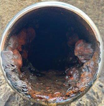
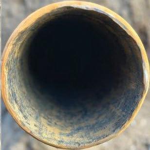
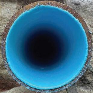

Bring New Life
Old Pipes To
Resiline 320 is projected to meet properties of ASTM F1216-16 after 50 years. Before
Affordably & Sustainably Restore service in as little as one day

Advantages of the SIPP In-Situ Lining Process
• Significantly extends asset life and improves water quality
• Prevents internal corrosion and tuberculation
• Helps reduce water loss and repair certain cracks and pinholes
• Helps restore internal pipe diameter and C factor
• Allows for same-day return to service


2026 | NORTHWEST

8 STRIKING A BALANCE IN THE NORTH: HOW EDMONTON GETS THE MOST FROM ITS WATER TRANSMISSION MAIN CONDITION ASSESSMENT PROGRAM
13 CONDITION ASSESSMENT AND REHABILITATION OF A 150-YEAR-OLD BRICK SEWER INVENTORY IN VICTORIA, BC
22 NASTT NO-DIG NORTH PROJECT OF THE YEAR 2025: LONG DISTANCE MICROTUNNELING IN CALGARY AVOIDS LANDSLIDE HAZARD FOR THE NOSE CREEK PROJECT









REAL WORLD LEARNING OPPORTUNITIES

T“A key highlight is the upcoming Edmonton Symposium, which will bring together industry professionals to share knowledge and innovations.”
he Northwest NASTT Chapter is actively advancing trenchless technology awareness and education across the region through a combination of events, partnerships, and strategic initiatives. A key highlight is the upcoming Edmonton Symposium, which will bring together industry professionals to share knowledge and innovations.
A major focus for the chapter is strengthening hands-on, practical learning opportunities in Manitoba and Regina. This includes collaborating with municipalities and project sites where trenchless technologies are actively being used. For example, the City of Selkirk’s CIPP (Cured-in-Place Pipe) projects are being leveraged as real-world learning
“A major focus for the chapter is strengthening hands-on, practical learning opportunities.”
environments, giving students and emerging professionals the opportunity to observe installations and engage with the technical considerations involved in selecting appropriate trenchless methods. Internally, the chapter is aligning its vision with updated strategic and financial planning efforts to ensure longterm sustainability and impact. At the same time, the team is heavily engaged in organizing the upcoming No-Dig North Conference, scheduled for Fall 2026, which will serve as a key event for knowledge exchange and industry collaboration across the region.

, NASTT

MESSAGE FROM THE CHAIR OF THE NASTT BOARD OF DIRECTORS
On behalf of the NASTT Board of Directors, I would like to extend my sincere appreciation to the members and volunteers of the Northwest Chapter for your continued dedication to advancing trenchless technology throughout the region. The strength of NASTT has always come from the energy, expertise, and commitment of its chapters, and the Northwest Chapter is an example of how local leadership can make a meaningful impact on our industry.
Your chapter has built a strong reputation for bringing together engineers, contractors, owners and manufacturers who are passionate about improving underground infrastructure through trenchless methods. From organizing educational events and seminars to fostering collaboration across disciplines, the work you do helps ensure that trenchless technology remains at the forefront of sustainable infrastructure solutions. These efforts would not be possible without the time and dedication of your volunteers. Whether you are serving on the chapter board, helping organize events, supporting student engagement, or simply showing up to share your expertise with peers, your contributions are deeply valued.
Looking ahead, I invite you to save the date for the 2026 No-Dig North conference, which will take place this fall right in your regional backyard in Calgary, Alberta, November 2–4, 2026. No-Dig North continues to grow as an important event for trenchless professionals across Canada and the northern United States. The conference will feature technical sessions highlighting innovative projects, an engaging exhibition hall, and valuable networking opportunities that bring together professionals from across the trenchless community.
Events like No-Dig North are made stronger by the involvement of our chapters and their members. Your participation helps ensure these gatherings remain vibrant, informative, and representative of the many perspectives that drive trenchless innovation.
Once again, thank you to the Northwest Chapter for your leadership, your enthusiasm, and your commitment to advancing trenchless technology. Your work strengthens not only your local community but the entire NASTT organization.
I look forward to connecting with many of you later this year in Calgary.
“Thank
you to the Northwest Chapter for your leadership, your enthusiasm, and your commitment to advancing trenchless technology.”
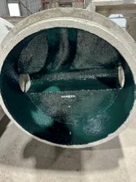
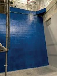
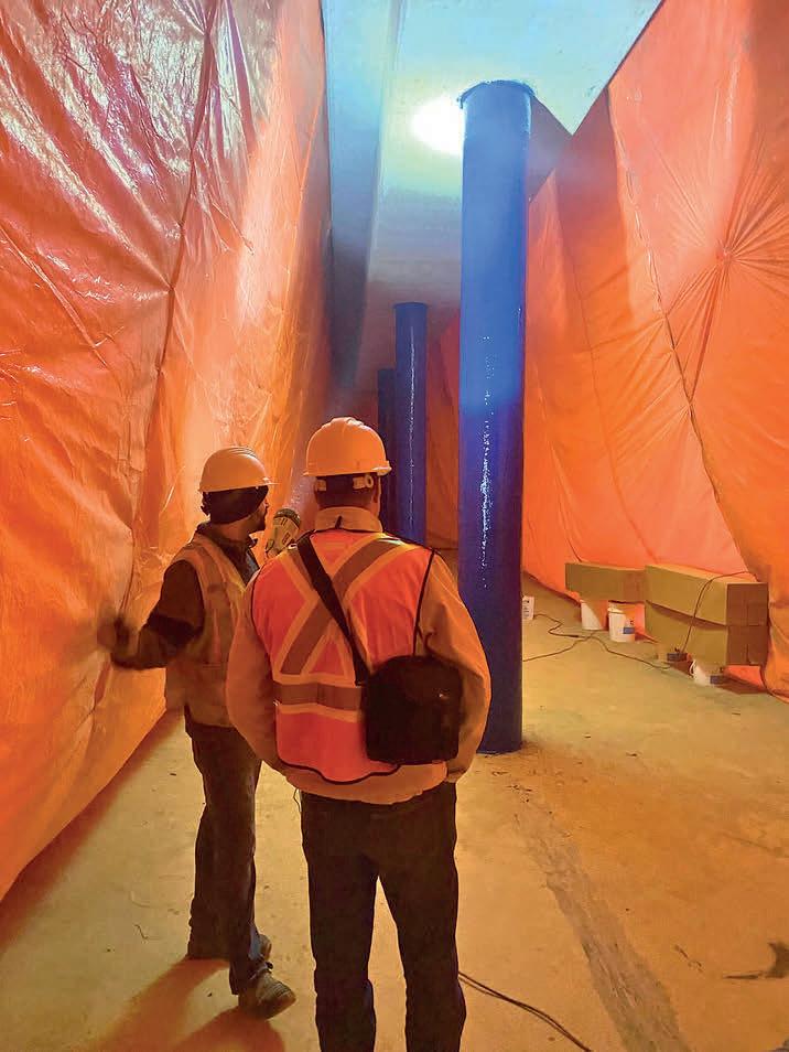
TCI ShieldStrong 955: Chemical-Resistant Protective Coating System for Concrete and Steel Infrastructure
TCI ShieldStrong™ 955 is a cost-effective, high-performance protective lining system designed to extend the life of concrete and steel structures in the harshest environments. It’s being used to protect new infrastructure before it goes in the ground— and to rehabilitate aging assets on some of the largest infrastructure projects across North America.




Greg Tippett
Chair Engineered for Durability. Certified for Performance.
Ideal for sewer and wastewater facilities.

Striking a Balance in the North
How Edmonton Gets the Most from Its Water Transmission Main Condition Assessment Program
Andrew (A.J.) Rees, P.Eng., CAPM, EPCOR Water Services Inc., Edmonton, Alberta
Josh Greenberg, P.Eng., Pure Technologies, a Xylem brand, Mississauga, Ontario
Justin Hebner, Pure Technologies, a Xylem brand, Vancouver, British Columbia
INTRODUCTION
EPCOR builds, owns and operates electrical, natural gas and water transmission and distribution networks, water and wastewater treatment facilities, sanitary and stormwater systems, and infrastructure in Canada and the United States. In 1996, EPCOR was incorporated as a standalone entity with the City of Edmonton (Alberta, Canada) as shareholder (EPCOR is municipally-owned), where they are headquartered. Edmonton, with a population of 1.4 million, is North
America’s northernmost major city. The weather is below freezing for a third of the year (the coldest day in 2024 was -47°C (-52°F)), compressing the construction season and posing significant challenges for utility operation, maintenance and construction. For example, the typical minimum depth of cover for buried pipe is 2.5 m (8.2') to the crown of the pipe to prevent freezing and damage due to frost.
EPCOR Water Services (EWS), an operating company of EPCOR, provides water and wastewater service to over one
“Edmonton, with a population of 1.4 million, is North America’s northernmost major city. The weather is below freezing for a third of the year (the coldest day in 2024 was -47°C (-52°F)), compressing the construction season and posing significant challenges for utility operation, maintenance and construction.”

million people in Edmonton, plus more than 90 communities and counties in the Edmonton Metropolitan Region and central Alberta. The water transmission system in greater Edmonton consists of approximately 510 km (320 mi) of water mains, which range in size from 350 mm (14") to 1525 mm (60") in diameter. EWS’ total average water demand in 2023 was 386 ML/d (102 MGD) and is approximately 70% within the City of Edmonton and 30% in the surrounding greater Edmonton regional water service area.
EWS has experienced growth in total water demand despite water efficiency improvements across the entire Edmonton region. Figure 2 shows the total Edmonton region water demand is increasing over time. However, this is due in large part
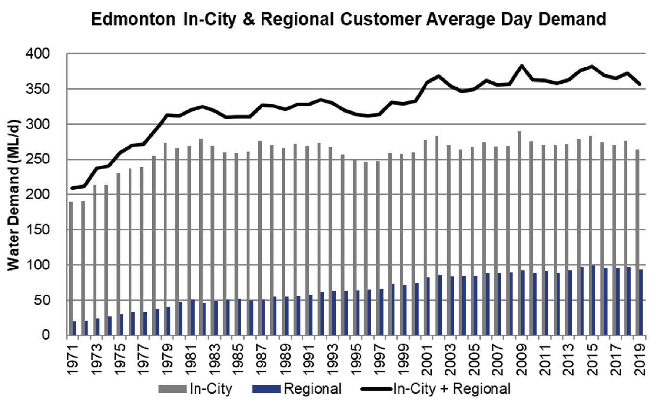
to continual growth in regional (outside Edmonton) water demand due to both population growth and an expanding regional service area. The segment representing in-city water demand has stayed relatively flat since the 1980s. In other words, though both Edmonton and the surrounding region are growing in population, only regional water demand has reflected this growth over the time scale shown in Figure 1.
“Repair costs
on
main breaks. Repair costs on a transmission main alone can easily reach $1 million and breaks with residual chlorine can result in a reportable environmental event to Alberta Environment and Protected Areas and may lead to fines and further investigation. Given the nature and size of transmission mains, breaks on these mains have the potential to cause broader and longer impacts for customers compared to breaks on distribution mains.
a transmission main alone can easily reach $1 million and breaks with residual chlorine can result in a reportable environmental event to Alberta Environment and Protected Areas and may lead to fines and further investigation.”
EWS WATER TRANSMISSION MAIN CONDITION ASSESSMENT PROGRAM
The water transmission system in Edmonton plays a critical role in transporting water to the secondary and tertiary pressure zones (primary zones are from the water treatment plants; these zones are downstream of reservoirs and booster stations), supplying regional customers, providing neighborhoods with high density fire flows, and providing adequate pressures during peak demand periods. The severity and consequence of transmission main breaks have been increasing with higher cost and environmental risk than distribution
For example, in 2011, an Edmonton water 650 mm (26") transmission main break made national news. Roads and basements were flooded, and residents were provided with temporary accommodations. The incident involved various City of Edmonton Emergency Response Departments. Maintenance response and repair costs were over $1.2 million CAD (2011 dollars) and damage claims from residents were estimated at over $1 million. EWS’ Water Transmission Main Condition Assessment Program was proposed to reduce the number of transmission main breaks, with the goal to
Figure 1: Edmonton In-City and Regional Water Demand (Source: EPCOR 2021)
identify distressed material within critical transmission mains so it can be targeted for replacement prior to failure occurring. Using desktop methods, EWS evaluated the risk of failure of transmission mains within Edmonton based on service numbers, redundancy, location and material. The likelihood of failure was then evaluated based on age and material of the mains. However, the likelihood of failure determined by desktop methods can vary based on the data available, and mains may act differently in the real world. EWS considered the following options to address the need to determine better likelihood of failure for the mains:
• Continue with the desktop studies for Likelihood of Failure (LoF) values –gives a best estimate of pipe condition, does not give exact location of potential breaks and only deals with the main as a whole. Can gather better data to support these studies (soil qualities) but accuracy would still be based on a risk factor.
• Internally inspect high risk of failure mains to get an exact condition assessment of the main – gives detailed information on main condition, can pinpoint damaged or deteriorated sections of the mains for spot repairs.
• Wait until break occurs and repair main then – can lead to significant customer impacts as well as economic, environmental and reputational impacts. Based on these options it was decided that using inline inspection technologies on high risk of failure mains would best meet the need for updating the condition knowledge of these mains.
EWS became aware of other municipalities implementing similar programs, which led to a pilot condition assessment project in 2019. Results were overwhelmingly positive and included an emergency replacement of one critical 900 mm (36") section of main, (see Figure 2) that would not have been identified unless it had failed, as well as multiple
proactive and planned repairs. The 2019 pilot indicated that a section of the transmission main can be inspected and repaired for less than 5% of the cost of full replacement.
Following the 2019 pilot, a new program was developed, categorized as reliability/life cycle replacement, with annual capital expenditures of $1.4 million budgeted and an annual pipeline inspection target of 10 km (6 mi).
INLINE INSPECTION TECHNOLOGIES
The scope of this program includes the inspection of transmission mains, 350 mm (14") in diameter or greater, that are determined to have a high consequence or likelihood of failure. The inspections
Risk Risk Mitigation
1. Financial - Inspections not able to be executed due to inoperable valves or flow control.
2. Financial and Operational Disruption - Tools becoming stuck in mains, leading to shutdowns.
• Valve inspections are completed before inspections are executed.
• Valves will be repaired if needed or other projects will be chosen.
involve the use of inline technologies that are selected based on the main material and size and include; inline radiographic or ultrasonic inspections, acoustic inspections, or pressure wave-based analysis. Figure 3 shows two inline inspection technologies EWS utilizes. There is inherent risk associated with inline free-swimming inspections on water transmission networks. The majority of these mains were not designed to accommodate such inspections, and challenges can include limited or no launch and retrieval locations, features such as butterfly valves, tees, reducers and offtakes, and non-comprehensive historical information (e.g., as-builts, repairs or modifications). With that said, inspection technologies have developed significantly
• Hydraulic modelling will be completed prior to inspection and flow testing will be completed.
• Planning meetings and a site visit with the contractor prior to the inspection will be completed to confirm operating conditions are suitable for inspection.
• Detailed investigation of the main and as-built drawings pror to the tool run will be completed.
• Planning meetings and a site visit with the contractor prior to the inspection will be completed to confirm pipeline in-situ conditions are suitable for inline inspection.
• EWS will preemptively run a small tool through the main prior to the larger tool runs to identify any issues that could arise
Table 1. Key Inline Inspection Risks and Mitigation
Figure 2: Distressed pipe section (left) and emergency repair (right)
Figure 3: Inline electromagnetic (left) and acoustic (right) free-swimming inspection tools (Source: Pure Technologies, a Xylem brand 2024)
over the last 20 years, with a proven track record of overcoming these challenges. In addition, EPCOR, the City of Edmonton, and the Government of Alberta have a deep knowledge and long relationship with pipeline inspection – there are over 440,000 km (273,000 mi) of regulated energy pipeline in Alberta (Alberta Energy Regulator).
EPCOR’s pipeline inspection experience helps it mitigate and accept the risks associated with inline free-swimming inspection technologies, which were selected because they keep the transmission mains in service (limited to no redundancy). Free-swimming inspection technologies are extremely efficient and cover long distances in a short amount of time, which mesh well with Edmonton’s weather constraints and short seasonal window. Table 1 below summarizes the risks associated with inline free-swimming inspection technologies and some of EWS’s mitigation plans.
Each year, EWS usually plans two weeks in the Spring and two weeks in the Fall to
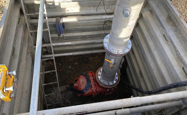
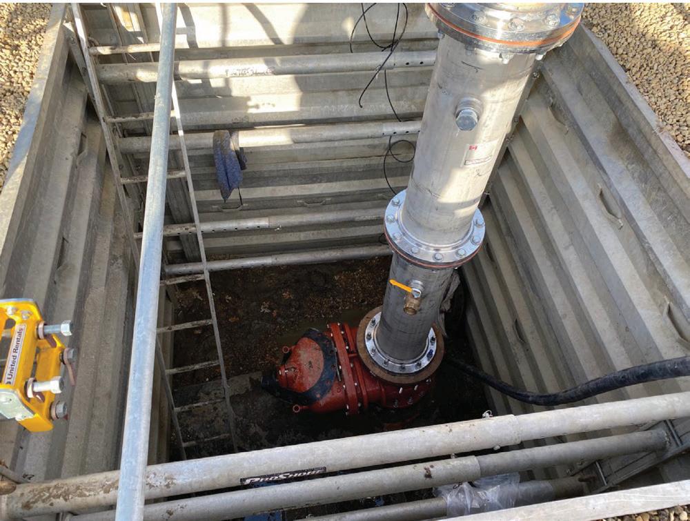
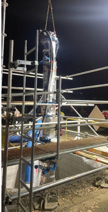
prepare and inspect its water transmission main network. Inspection planning is detailed and preparation typically includes construction of new launch and retrieval points. To accommodate high-resolution pipe wall assessment tools, EWS creates access points by wet tapping the main and installing a 400 mm (16") valve to allow for live tool launch and retrieval – no line shutdowns are required for the preparation or inspection. Figure 4 shows some of EWS’ inspection preparation.
RESULTS AND CONCLUSION
Since the program’s 2019 start, EWS has inspected 38 km (24 mi) of water transmission main and over 1,300 valves in Greater Edmonton. Table 2 provides a full list of EWS inline inspection program results.
EWS has proactively detected and repaired multiple pipe defects and leaks identified by inspection and condition
assessment, ensuring capital dollars are spent correctly, the integrity of the transmission system is maintained at the highest standard, and large, impactful breaks that can become common as the transmission system ages are avoided. As a result, the system now has an additional 38 km (24 mi) of low-risk transmission mains, at less than 5 percent of the cost of replacement.
EWS’ program prioritizes its water transmission mains for inline inspection to evaluate the condition, determine where repairs are required and reduce the number of breaks, which in turn prevents customer, economic, financial and reputational impacts. EWS’ current plans are to accelerate the inspection program to complete two high resolution transmission main inspections per year until all critical mains have been inspected. Once complete, a re-inspection schedule will be created based on the recommendations from the original inspections, while updating the risk model and adding any new identified mains to the list. Utilizing inline inspection technologies provides EWS with high-resolution condition data and helps the program overcome unique challenges present in North America’s northernmost major city.
REFERENCES
Ellison, D. (2019). Condition Assessment of Water Mains, Manual of Water Supply Practices - M77, American Water Works Association (AWWA), Denver, CO. Case Study: A Northern Alberta utility’s proactive approach to assessment avoids potential catastrophic holiday failure, UESI Pipelines Conference 2021. 2022-2026 Water Cycle Utilities Performance Based Regulation (PBR) Applications, EPCOR Water Services Inc. (Feb. 2021).
Table 2. EWS Water Transmission Main Condition Assessment Program Results
Figure 4: Wet tap with launch tube (left) and insulated retrieval/extraction tube (right)



“Since
2009, AECOM has been actively engaged in the condition assessment and rehabilitation of the City’s brick storm drain network, which includes trunk sewers initially constructed in the 1860s.”

Condition Assessment and Rehabilitation
of a 150-year-old Brick Sewer Inventory in Victoria, BC
Eric Leydon, P.Eng., AECOM Canada ULC, Victoria, BC
Chris Macey, P.Eng., AECOM Canada ULC, Winnipeg, MB
INTRODUCTION
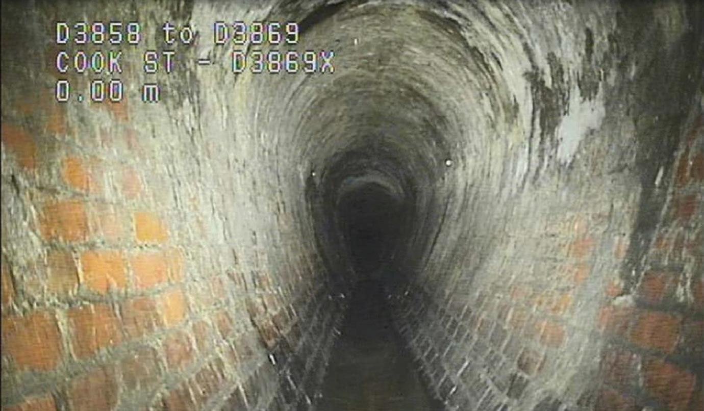
Since 2009, AECOM has been actively engaged in the condition assessment and rehabilitation of the City’s brick storm drain network, which includes trunk sewers initially constructed in the 1860s. Originally functioning as combined sewers, these brick pipes have since been transitioned exclusively to stormwater conveyance following the development of a dedicated sanitary sewer system. The brick inventory comprises various cross-sectional geometries that follow the original stream beds and low points within the city’s natural topography.
ASSET INVENTORY INVENTORY OVERVIEW
The brick storm drain inventory comprises egg, arch, and circular shape cross sections of
varying sizes that total approximately 10 km throughout the city.
Although the cross sections are generally categorized as either egg-shaped or arch, the egg-shaped sewers exhibit multiple variations in composite material construction, incorporating both concrete and brick. Most egg-shaped sewers are characterized by brick laid upper arches; however, variants include sewer segments with concrete sides and a brick invert, complete concrete lower portions with brick uppers, concrete lower portions with bedrock uppers, and entirely brickconstructed segments. In contrast, all arch sewers are constructed entirely from brick. The 3:2 (height to width ratio) egg shape is a standard egg-shaped cross section that has been widely used in the construction of egg-shaped brick sewers in North America and the U.K.
The arch cross sections are less common in sewer networks and are not defined by any set standard although classical arches are more commonly parabolic in shape. The arch type cross sections found in the City’s storm drain network appear to follow two heightto-width dimensional ratios: 2:3 (Arch1) and 3:4 (Arch2), neither of which are parabolic arches. Figure 1 shows a breakdown of the City’s inventory of brick sewers by length and corresponding cross section type.
There are 12 distinct sizes of egg-shaped sewers found within the City’s assessed inventory, all with the height-width ratio of 3:2. See Figure 2 for a typical egg-shaped sewer encountered in the Victoria brick inventory.
Circular cross section pipes account for only a small portion of the brick inventory. Approximately 550 metres (m) of circular brick pipe ranging in diameter from 860 millimetres (mm) to 1320 mm can be found in the system. Arch 1 and Arch 2 cross sections are both arch pipe sewer cross sections but with distinctly different height to width ratios. The Arch1 designation indicates a height to width ratio of approximately 2:3 while the Arch 2 indicated a ratio of approximately 3:4. The Arch1 type includes 13 distinct size classes, while the Arch 2 type is found in one size only.
RISK PROFILE OF INVENTORY
The Water Research Centre’s (WRc) Sewerage Rehabilitation Manual (SRM) provides a prescriptive method for risk classification of sewer inventories, classifying sewers into various categories based on the failure consequences, economics, and the public and environmental impact of failure. This process is referred to as defining the Critical Sewer Network.
“The City’s brick storm sewer network has been assessed using the WRc classification methodology and the entire brick storm system falls into the Category A risk profile due to size, functional significance and material type (which drives up retroactive repair costs).”
The entire network is broken into three categories of sewer, Category A, B, and C. In broad economic terms the characterization of the three overall categories can be described as follows:
• Category A – The overall cost (the sum of both direct and indirect cost) of a post collapse repair is greater than 6 times the cost of a planned repair at the optimum point in the deterioration cycle.
• Category B – The overall cost (the sum of both direct and indirect cost) of a post collapse repair is from three to six times the cost of a planned repair at the optimum point in the deterioration cycle.
• Category C – The overall cost (the sum of both direct and indirect cost) of a post collapse repair is less than three times the cost of a planned repair at the optimum point in the deterioration cycle.
The Critical Sewer Network is comprised of all Category A and B sewers. This grouping consists of sewers that have at least one of the following characteristics:
• High benefit to cost ratio in terms of proactively carrying out rehabilitation prior to Failure,
• Cost to repair the sewer in the event of failure is high,
• Located in roads where the disruption to traffic in the event of a sewer failure will be considerable, resulting in high to very high traffic delay costs,
• Considered strategically important and critical to the operation of the overall system. Category C sewers are non-strategic sewers that are characterized by much lower benefit to cost ratios in terms of proactively carrying out rehabilitation prior to failure.
The City’s brick storm sewer network has been assessed using the WRc classification methodology and the entire brick storm system falls into the Category A risk profile due to size, functional significance and material type (which drives up retroactive repair costs).
To differentiate the level of risk encountered in the Victoria brick storm drain system, a subclassification was made to flag pipe segments in critical or sensitive areas. Sewer entities in the inventory that lay beneath buildings or other sensitive areas (e.g., the sewers underneath a cemetery) may result in more dire consequences upon
Figure 2: Typical Brick 3:2 Egg Shape Sewer
Figure 1: Percentage of Cross Section Type by Length
failure as compared with other segments of the inventory. These sewers have been classified as Category A-1 and all others are deemed Category A-2. The methodology and approach to categorizing risk was first developed for the Cook St./Fairfield area in 2009 and then applied to the remainder of the inventory.
Examples of segments receiving Category A-1 classification in the Cook Street/Fairfield area include sewers running between Joseph Street and Eberts Street, underneath houses in a residential neighbourhood, and under the Mountain Equipment Co-op Retail Store. All sewers in the assessed brick storm drain inventory should be treated from a policy perspective as WRc Category A sewers with additional prioritization given to the Category A-1 sewers herein.
GEOTECHNICAL CONDITIONS
The general soil stratigraphy along the alignments of the brick storm drains in the City of Victoria is:
• Topsoil/asphalt
• Stiff to very stiff brown silty clay
• Firm to stiff grey silty clay
• Glacial till overlying bedrock
Local deposits of sands and gravelly sands can be found throughout the area, likely from periods of higher sea levels. The clay in the area is of a marine origin and commonly referred to as Victoria Clay. The thickness of the clay and glacial till is highly variable depending on the bedrock topography. The ground water table is typically present within 2 to 3 m of the ground surface and fluctuates seasonally.
There are also regions which were filled in over 100 years ago to allow for development. These areas were former swamps and contain deposits of random fill material and organicrich silts with peat deposits. Over half of the combined length of the brick storm drains in the Cook Street/Fairfield section are located in the former swamp areas.
SUMMARY OF STRUCTURAL DETERIORATION OF SEWERS
To understand the causes of sewer collapse and the importance of current condition
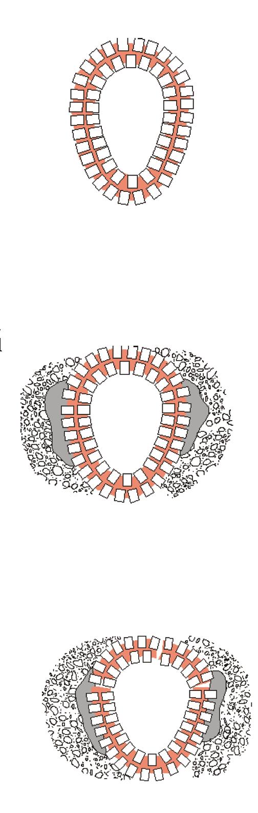
Stage I
Mortar loss allows infiltration and soil loss –Mortar loss and infiltration
The initial defect in the deterioration process of a brick sewer is the loss of mortar at the joints. The mortar loss eventually facilitates the infiltration of the ground water or the exfiltration of flow caused by surcharging of the sewer. The visible defects at this stage will be mortar loss, infiltration and opening of the joints.
Stage 2
Additional soil loss allows spring line to expand and crown to crack and drop – Deformation and cracking on crown
The infiltration and exfiltration permit further deterioration of the sewer by washing-in adjacent soil particles. The soil loss results in voids or zones of low compaction forming outside the sewer wallls and consequently an uneven load distribution on the sewer structure. The formation of voiding in conjunction with the uneven load distribution willl eventually cause the sewer to deform or “spread” at the spring line and the crown of the sewer to flatten. If the compression face transitions completely out of sections of the inner brick layer, localized sections of the inner brick layer may fall.
Stage 3
Soil loss increases – Deformation to heart shape, fracture at crown and possible loss of bricks
The compressive load that was once constant and uniform is ultimately compromised by the lack of side soil support. The sewer will develop a subtle “heart” shape with the continued “spreading” of the sewer at the spring line and the crown eventually collapses. As in Stage 2, as larger sections of the inner ring lose compression, larger sections may preferentially fall out without total loss of the outside ring.
state observations, it is essential to first examine the primary factors responsible for sewer deterioration. Key elements include the surrounding soil type, the internal hydraulic regime, the method of construction, groundwater levels, the characteristics of the sewage conveyed, and the loading experienced by the sewer. These factors should be analyzed in conjunction with detailed observations of internal sewer conditions to facilitate a comprehensive assessment of collapse risk.
Collapse of sewers normally originates from an initial, often minor, defect. It is the defect that permits further deterioration. Initial defects may be caused by:
• Cracking from excessive vertical loads or poor bedding conditions
• Poor construction practices (e.g., installation damage, improper lateral connections)
• Leaking joints
• Third party damage
• Fabric decay (e.g., concrete corrosion, loss of mortar in brick sewers, etc.)
“There are also regions which were filled in over 100 years ago to allow for development. These areas were former swamps and contain deposits of random fill material and organic-rich silts with peat deposits. Over half of the combined length of the brick storm drains in the Cook Street/Fairfield section are located in the former swamp areas.”
Figure 3: Stages of Brick Sewer Deterioration
“The actual collapse of sewers is usually triggered by a random event that is unrelated to either the cause of the original defect or the primary cause of the deterioration. Random events would include earthquakes, severe rainstorms, water main breaks, nearby excavations, or live loads from construction traffic.”
The deterioration process very often involves the ground around the sewer. This is caused by flow of water in and out of the pipe that leads to ground loss in the adjacent soil. The ground loss contributes to the eventual development of unbalanced loading on the pipe. Third party damage may include excavations in proximity to deteriorated sewers or direct damage in excavations. Deterioration of the sewer fabric is usually related to general acid or hydrogen sulphide attack. Deterioration of sewer fabric is much less common in storm drains than in sanitary sewer applications.
The actual collapse of sewers is usually triggered by a random event that is unrelated to either the cause of the original defect or the primary cause of the deterioration. Random events would include earthquakes, severe rainstorms, water main breaks, nearby excavations, or live loads from construction traffic. Brick sewers, by virtue of their increased reliance on the adjacent soil structure, are extremely prone to collapse by third party damage from adjacent excavations. As it is the random event that precipitates a collapse it is not possible to predict exactly when a collapse will occur. Fortunately, it is possible to exercise good judgment to assess whether a sewer has deteriorated sufficiently for a collapse to be possible based on the observed level of structural distress and other relevant factors.
Non-circular cross section sewers have an added degree of complexity in that the stress distribution transitions within the pipe wall from compressive to tensile forces differ substantially from circular pipe. This means that structural distress in these structures is markedly different than in circular sewers, a point that is critical for the reviewer to be aware of, during the condition assessment process. The structural performance of all brick sewers relies entirely on reasonably constant uniform compression as a result of its interaction with the surrounding soil structure. Any loss or weakening of the soil adjacent to the sewer structure will facilitate the deterioration process. Further, as the compression face in some areas of the sewer migrates away from the inner ring of brick,
complete layers of brick can fall rather suddenly as a result of being exposed to tensile forces.
An example of how mortar loss and subsequent leaching of surrounding soils can lead to void creation and subsequent sewer collapse is shown in the extract from the WRc’s Sewer Rehabilitation Manual in Figure 3. The process of sewer collapse can be divided into three stages:
CONDITION ASSESSMENT METHODOLOGY
The intent of the Condition Assessment process is to attach a Condition Grade to each
5 Collapsed or collapse imminent
4 Collapse likely in the near future
reach of sewer based upon the worst defect in that reach. This is normally a two-step process involving the assignment of a preliminary Internal Condition Grade (ICG) based on the raw defect scores obtained from CCTV inspections and a Final Structural Performance Grade (SPG) based on the consideration of supplementary data, including:
• Soil Type Considerations
• Effect of Surcharging
• Surface and Fabric Wear
• Past Maintenance History
• Other Factors
This process was modified slightly for this inventory as brick sewers inherently have numerous defects (both major and minor
3 Collapse unlikely in the near future but further deterioration likely
2 Minimal collapse risk in the short term but potential for further deterioration
1 Acceptable structural condition
Table 1: Condition Grade Description
5 Already collapsed; or Deformation >10% and fractured; or Extensive areas of missing bricks and/or Displaced/hanging brickwork; or Missing invert
4
3
Deformation 5-10% and fractured or total mortar loss; or Small number of missing bricks; or displaced/hanging brickwork; or Moderate loss of level; or Frequent badly made connections; or Dropped invert.
Deformation 0-5%, no fracture and only moderate mortar loss; or Displaced bricks; or Total mortar loss without other defects; or Occasional defective connections.
2 Minor cracking; or No deformation or loss of bricks; and Mortar loss confined to suface, and Line and level as built; and Connections satisfactory.
1 No structural defects.
Table 2: Qualitative Description of Internal Condition Grade for Brick Sewers
Year Description
2009 AECOM assessed 5600 m of video provided by the City of Victoria for pipe segments in the Cook Street/Fairfield Road area.
In October 2009 AECOM submitted the initial Draft report containing the assessment of the brick mains within the Cook Street/Fairfield Road area. The report rationalized remedial upgrading options, and then prioritized those upgrading requirements into short, medium, and long-term upgrading programs.
2010-2011
• AECOM worked with AquaCoustics to attempt 1600m of new video in the Cook Street/Fairfield area. The total length of new video acquired was 890 m. Along with the AquaCoustics video, AECOM also included 2400 m of video taken in 2007 and assessed by a previous consultant.
In January 2013 AECOM submitted an update to the report to reflect the updated rehabilitation prioritization based on the incorporation of the additional video.
2013 AECOM worked with McRae’s Environmental Services Ltd. to acquire approximately 2500 m of new video. This inspection program expanded the scope of the Brick inventory to include all segments not previously attempted, including areas outside of Fairfield/Cook Street.
• In November 2014 AECOM submitted an update to the report to reflect the updated rehabilitation prioritization based on the inclusion of the new video.
defects) that when considered in a conventional computerized scoring approach tends to overstate the severity of the true condition state. To provide a more realistic review of both failure risk and rehabilitation requirements, each MH-to-MH reach was assigned a distinct condition state based on consideration of:
• Overall structural stability
• The nature of the driver defects in terms of how they would impact the deterioration process.
The WRc Condition grades were used for this discrete assessment and are broken down into five categories or discrete condition states based on the potential for collapse and the likelihood of further deterioration. The implication of each condition grade is summarized in Table 1.
Qualitative descriptions of each condition grade are presented in Table 2 for brick sewers.
2015
• AECOM worked with McRae’s Environmental Services Ltd. to acquire approximately 6500 m of video. With the acquisition of this video, all entities within the Victoria Brick storm drain inventory had been inspected within the last 5 years.
2017 AECOM worked with McRae’s Environmental Services Ltd. to acquire approximately 5200 m of video. This program focused on obtaining updated CCTV for all SPG 3 and 4 entities.
2019 Report submission based on 2017 footage to update the rehabilitation prioritization and mapping of completed segments to date.
2020 • AECOM worked with McRae’s Environmental Services Ltd. and Camtux to acquire approximately 5200 m of video. This program focused on obtaining updated CCTV for all SPG and 4 entities assessed in the last 7 years. Report submission April 2021.
2023
• AECOM worked with Camtrux to acquire approximately 1000 m of video. This program focused on obtaining updated CCTV for a selection of the top assets of Prioritized Project List, including SPG 3 and 4 entities.
INSPECTION PROGRAM HISTORY
AECOM has supported the acquisition of CCTV of the City’s brick drain system at regular intervals since the commencement of involvement in 2009. A summary of the inspection programs to date is noted in Table 3.
“The intent of the Condition Assessment process is to attach a Condition Grade to each reach of sewer based upon the worst defect in that reach.”
CONDITION ASSESSMENT SUMMARY
As of mid-2025, the length weighted condition of the assessed brick inventory is summarized as follows:
• 0% are facing the threat of imminent failure (SPG 5)
• 5% of the sewers are in more advanced states of deterioration (SPG 4)
• 31% of the sewers are in the critical transition condition state (SPG 3)
• 64% of the sewers are in good condition (SPG 1 or 2 – lined and unlined)
The condition-state of the inventory can be summarized graphically as per Figure 4.
A total of 5,129 m of brick arch, egg, and circular pipe has been lined using CIPP & GRP technology over the course of
Table 3: Inspection Program History
Figure 4: Length vs. SPG Rating
10 construction contracts since 2011. The resultant proportion of the Victoria Brick inventory that has undergone rehabilitation is shown in Figure 5.
LINING TECHNOLOGIES CONSIDERED
Surface features within the brick storm drain service areas generally include:
• Mature tree growth,
• A balance of sensitive commercial and residential areas,
• Moderately high traffic volumes in the commercial areas, and
• Portions of inventory under houses or other buildings.
Open cut sewer renewal in these areas would not be desirable, from the perspective of its impact on the public or the environment and lack of cost effectiveness. The City has a tacit policy of maximizing the use of trenchless technologies and in many locations, it would be the only way to implement remedial works without substantial disruptions to traffic and disturbance of sensitive surface infrastructure features. Due to the shape, size of the sewers (most are person accessible), and the general condition (very little major deformation or loss of pipe fabric) the preferred method for rehabilitation is lining technology.
The primary rehabilitation technologies applicable to non-circular sewers in Victoria
are cured in-place pipe (CIPP) and glass reinforced plastic (GRP) segmental liners. Both technologies have their advantages and disadvantages and have been used successfully for over 25 years. Cured-in-Place-Pipe (CIPP) lining is often chosen as a desirable approach as it has minimal impact to the pipe’s crosssectional area and hydraulic capacity. CIPP is typically a more cost-effective method, however, is subject to a maximum host-pipe diameter in the range of 1800 mm to 2400 mm for circular pipes. CIPP lining of non-circular pipes requires additional design scrutiny, especially when considering the tight radii often encountered in the bottom corners of arch pipe.
Slip-lining with prefabricated GRP sections reduces the available cross-section and conveyance capacity, however, many of the sewers in the City’s brick drain network are not undersized, largely due to installation of system redundancy and separation of combined flows over the years. GRP lining is often more suitable for large arch sections since it can be custom manufactured to fit nearly any host pipe shape or size, or through locations with challenging geometry, such as curves, drops or steps.
LINER DESIGN
Prior to 2021, the Water Research Centre (WRc) Sewerage Rehabilitation Manual (2001) served as the key design guide for determining liner thickness in noncircular sewers. The shortfall with the WRc approach was that the equations used were limited to two types of host pipe geometry – oval and egg. The design approach for arch pipe involved applying engineering judgement to the loading conditions and effective beam length used as inputs in the published formulae.
Liner design for circular pipe leaned on the formulae published in Appendix X1 of ASTM Standard F1216.
In 2021, the American Society of Civil Engineers (ASCE), in conjunction with NASSCO and the Utility Engineering and Surveying Institute (UESI), published Manual of Practice 145 – Design of CloseFit Liners for the Rehabilitation of Gravity Pipes (MOP 145). This manual consolidates research conducted worldwide in pipeline
rehabilitation and aims to provide design guidance for rehabilitation of sewers for circular and non-circular geometries, including arch, egg, elliptical, box and other non-defined shapes.
AECOM’s liner design approach in recent years has transitioned to the MOP 145 design method. The most recent projects designed for the City of Victoria brick drain rehabilitation program have relied on designs produced via AECOM’s in-house tool and verified by the proprietary tool that was developed in conjunction with MOP 145.
PROCUREMENT CONSIDERATIONS
Rehabilitation of large diameter sewers by trenchless methods is a challenging process and owners rely on suitably qualified construction companies to undertake the work. For the last decade, the City of Victoria has used a prequalification process to confirm that interested contractors have the skill, experience and equipment to undertake the work. For all liner suppliers and installers, the current qualification requirements include:
• Third party test results to prove physical properties of lining products,
• Proof of relevant experience and reference contacts from three previous projects,
• Sample liner design calculations sealed by a professional engineer,
• Submission of acceptable QA/QC procedures.
Specific to CIPP suppliers / installers:
• Minimum of 10 km of successfully installed liners in sewers < 900 mm diameter,
• Minimum of 1 km of successfully installed liners in sewers > 900 mm diameter,
• Minimum of 1 km of successfully installed liners in sewers that are non-circular.
Specific to GRP suppliers and installers:
• Minimum of 3 successfully installed liners in sewers that are non-circular.
This prequalification approach has yielded positive results for the City of Victoria. All lining projects administered by AECOM this program have been successfully completed.
“Rehabilitation of large diameter sewers by trenchless methods is a challenging process and owners rely on suitably qualified construction companies to undertake the work. For the last decade, the City of Victoria has used a prequalification process to confirm that interested contractors have the skill, experience and equipment to undertake the work.”
Figure 5: Rehabilitation Progress
North American Society for Trenchless Technology’s 2025 Project of the Year Award
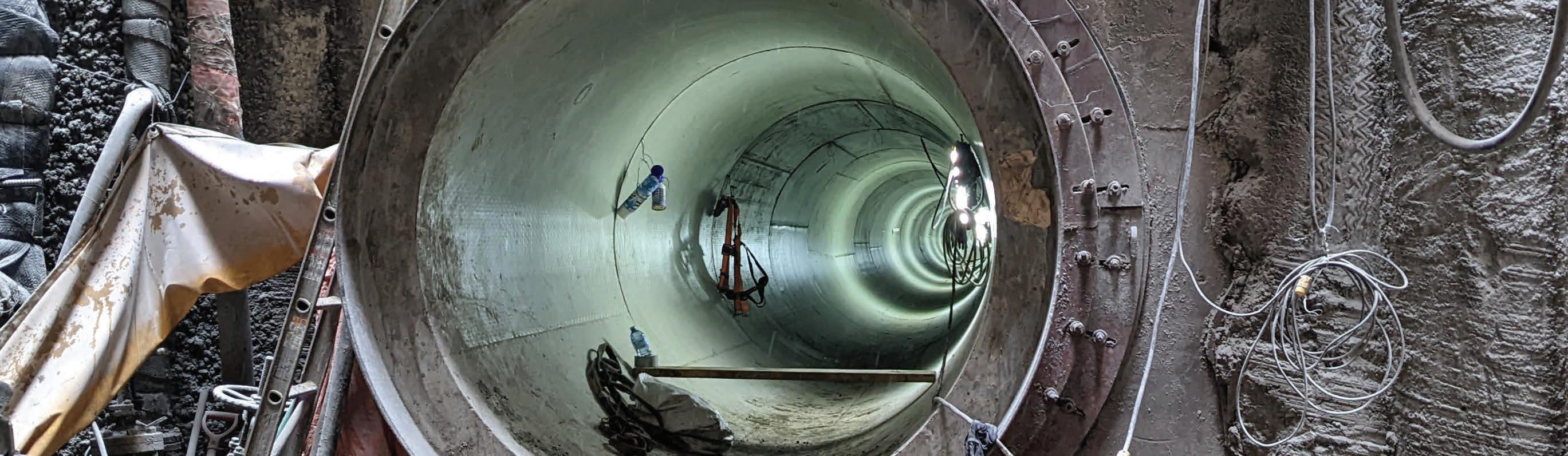
Congratulations to our team, including Jason Lueke, Chris Lamont, Sam Saunders, Rowan Shields, Mike Paulsen, Greg Walker, and many others involved on this multi-award-winning project. The 99th Avenue Sanitary Trunk Sewer has been a critical component of the City of Edmonton’s wastewater collection system since the 1970s. This two-stage project involved rehabilitating approximately 1.1 kilometres of monolithic concrete archshaped sanitary trunk sewer located about 30 metres below ground. This project also recently received an Award of Excellence at the ACEC National Awards.
www.ae.ca

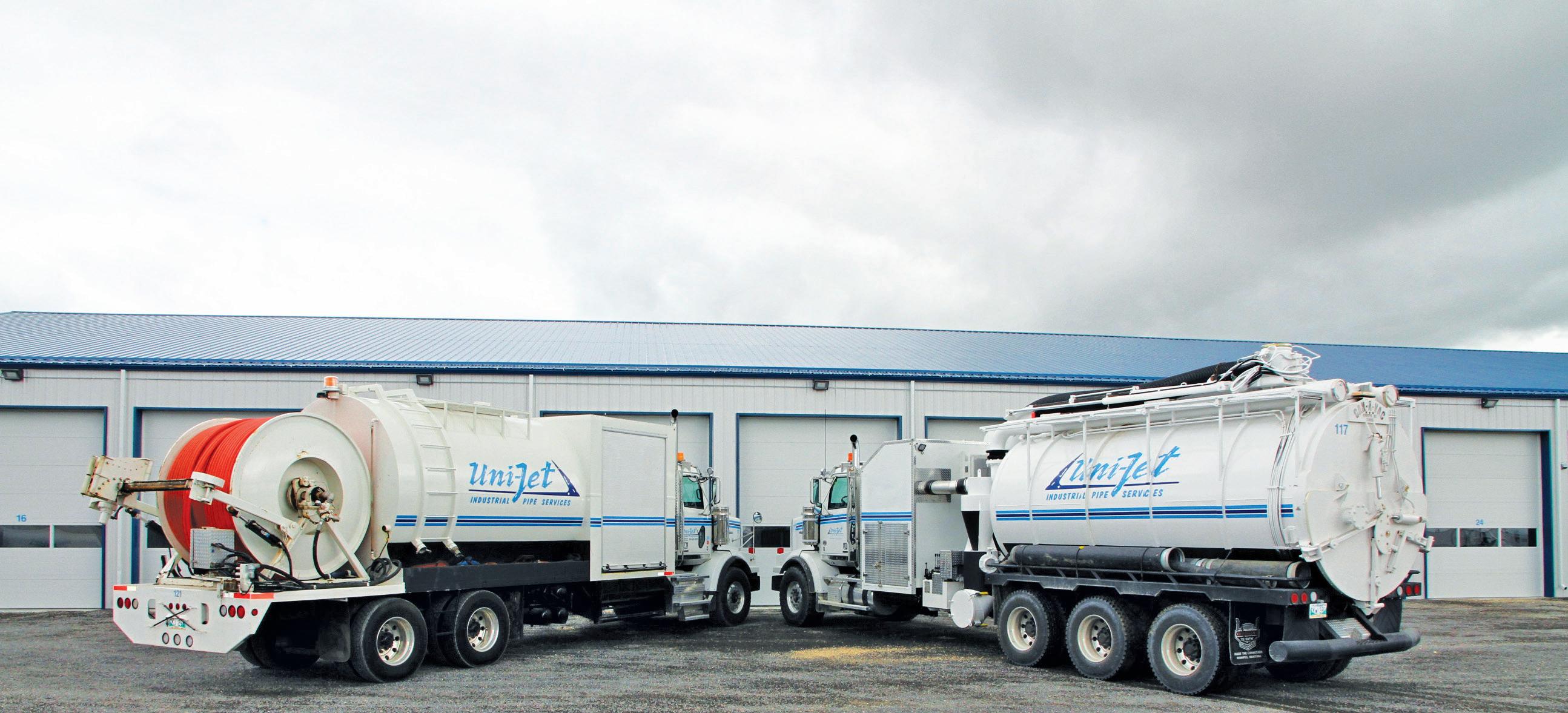
SPECIALIZING IN LARGE DIAMETER PIPE CLEANING
RUN THE UNDERGROUND.
Take on every bore path with confidence, from pilot drilling through reaming and pullback, backed by complete underground solutions and nationwide support from Brandt.
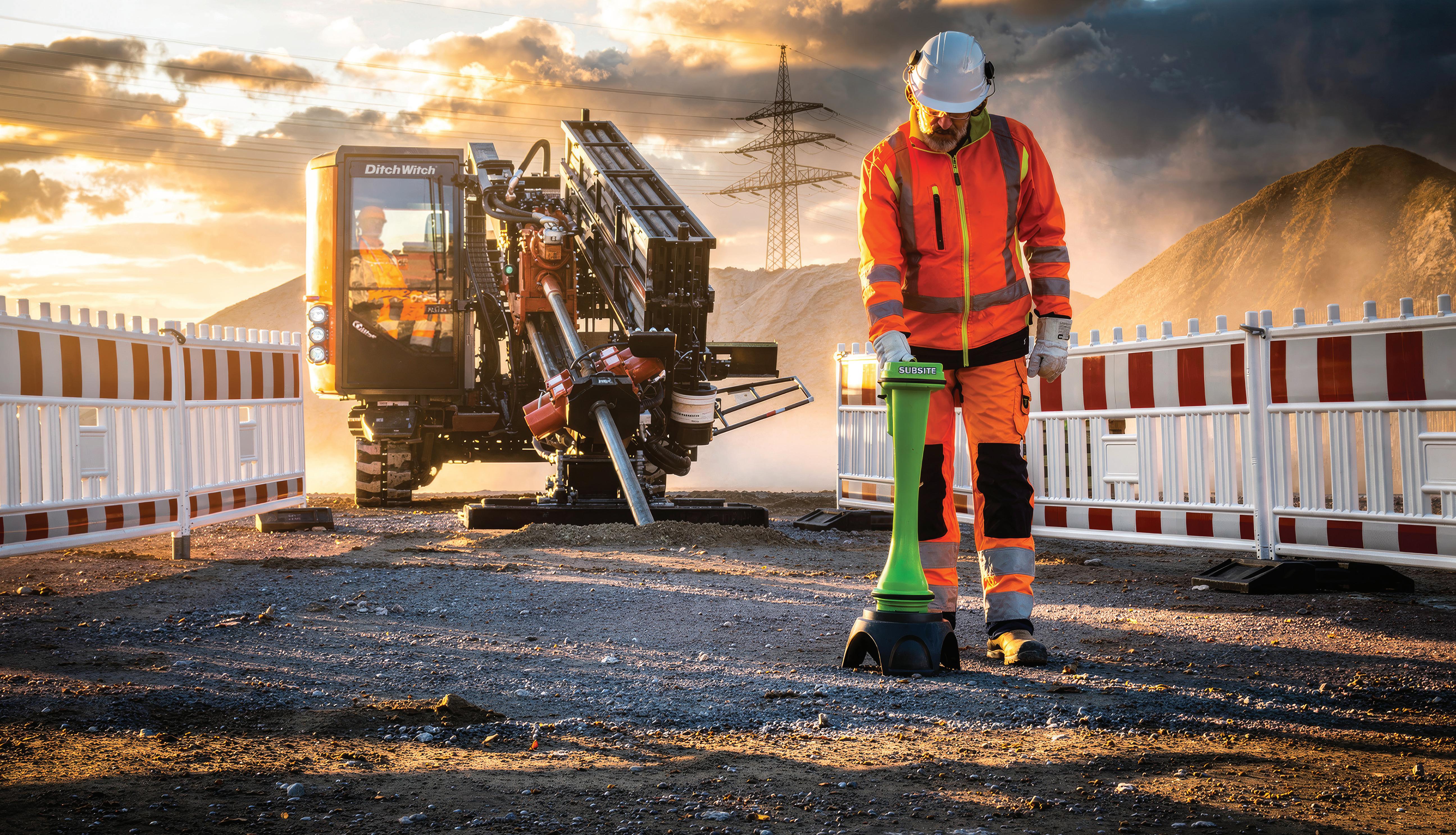


Drill faster and get more done with Ditch Witch® JT120 HDD performance.
Stay on line and avoid rework with the Subsite® Marksman HDD Guidance System.
Keep crews working with 100+ Brandt service points and 24/7/365 support.
Long Distance Microtunneling in Calgary
Avoids Landslide Hazard For The Nose Creek Project

NASTT No-Dig North Project of the Year 2025
Andrew Finney, PE, GE, P.Eng., Jacobs Engineering Group, Sacramento, CA
Mohi Parata, Ward and Burke, Calgary, AB
Zulfiqar Khowaja, P. Eng., City of Calgary Infrastructure Services, Calgary, AB
INTRODUCTION
The City of Calgary (The City) is experiencing continuous development in the northern part of the city. To accommodate new developments and enhance sanitary sewer capacity The City started a phased upgrade of the existing sewer system in 2011. Phases A and C of the upgrade were completed in 2017, while Phase B was further subdivided into five contract packages. This paper addresses the design and construction of the final contract package of Phase B (Contract 4), which includes construction of a twinning sewer for approximately 1.4 miles (2.3 kilometres) and consisting of reinforced concrete sewer pipe with an HDPE liner, as seen in Figure 1. Of the approximately 7,400 feet (ft) of Contract 4, approximately 5,000 ft (1,501 meters [m]) was installed using trenchless methods along the west bank of Nose Creek, which is a current record single-drive length for 66-inch (in) (1,650-millimeter [mm]) pipe, while another 850 ft (260 m) of 60-in (1,500-mm) pipe was installed using trenchless methods beneath Nose Creek.
PROJECT DESIGN
The original concept for Phase B (Contract 4) utilized primarily open trench installation of the sewer pipe on the east side of Nose Creek, with trenchless methods planned to cross Nose Creek and 64th Avenue. Thurber Engineering LTD (Thurber) completed a
preliminary geotechnical assessment in 2009 that addressed all of Phase B from 32nd Avenue NE in the south to 144th Avenue N.E in the north (Thurber, 2009). The report provided a summary of the geotechnical investigations carried out within the study area and included relevant available geotechnical data for use during conceptual design.
As the project progressed into preliminary design an asset value management (AVM) process was undertaken using a route selection tool to rank potential route combinations, weighted for the following five main categories: economic, social, environmental, timescale risk, and technical risk. The tool generated a matrix and provided an associated weighting for each route. The AVM process provided a guidance framework for identifying the detailed route. The final route was selected after receiving stakeholder input and City review and is shown in Figure 1 above.
In 2011, Thurber followed up with a Contract 4 Geotechnical Assessment for the portion of Phase B from Beddington Trail to 32nd Avenue NE (Thurber, 2011). At this time the alignment had been relocated to the west side of Nose Creek to afford better access to the installed pipeline which was originally bounded by the creek and Alberta Transportation’s Deerfoot Trail and due to the presence of high voltage power lines, a future widening of Deerfoot Trail, and the potential for high-speed rail tracks.
SLOPE STABILITY CONCERNS
Subsequent to the 2011 Geotechnical Assessment, Thurber identified a risk of slope instability during open cut trenching north of 64th Avenue NE. Specifically, Thurber noted that the subdivision at the top of the hillside west of the alignment and north of 64th Avenue NE was constructed on the site of an old quarry. Inspection of historical aerial photography suggested to Thurber the potential that uncontrolled side cast fill was present on the hillsides west of the alignment and that this fill could be destabilized by the planned 50-foot (15-m) deep trench planned for the trunk sewer. In 2013 the City of Calgary authorized Thurber to assess the stability of the slopes to the west of the planned the sewer alignment. Thurber drilled two test holes at the top and bottom of the slope at two locations and conducted two test pits about halfway up the slope at each location.
Thurber’s subsequent evaluation (Thurber, 2014a) identified that an open cut would require 1H:1V (horizontal: vertical) slopes to maintain stability, resulting in a trench width
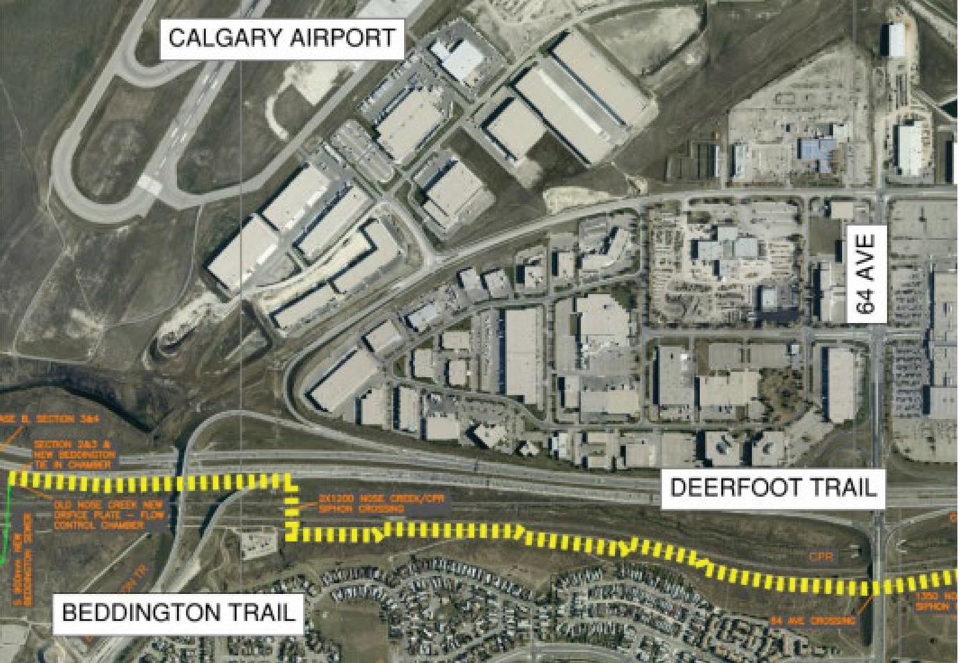
“As the project progressed into preliminary design an asset value management (AVM) process was undertaken using a route selection tool to rank potential route combinations, weighted for the following five main categories: economic, social, environmental, timescale risk, and technical risk.”
of approximately 65 ft (20 m) at the top. Thurber was concerned that deep excavation at the toe of the steep slopes may destabilize the existing uncompacted soil slopes, resulting in distress to the slope and the homes above, and possibly displacement and failure of the trench below. For the traditional open cut sloped trenches, Thurber’s assessment showed that factors of safety for the undrained (short term) condition ranged from 1.5 to 2.5, indicating that the slopes should be stable if excavation, pipe installation, and backfilling were completed as a rapid continuous operation leaving no section of the trench open for more than a few days. However, factors of safety for the drained (long term) condition ranged from 0.89 to 1.1, an indication that the slopes could become unstable if the excavation is left open and unsupported for too long. With the proposed 1H:1V slopes the trench width was also predicted to encroach into the adjacent Canadian Pacific Kansas City (CPKC) right of way (ROW). Thurber also evaluated the stability of a shored and braced trench option and determined that this option was feasible and was not predicted to result in slope movement.
In addition to the stability concerns, an existing 24-in (600-mm) diameter water main runs along the toe of the slope approximately 15 ft (5 m) to the west of the centreline of, and parallel to, the proposed trunk sewer. This waterline could be shut down and taken out of service during trunk sewer construction but would need to be replaced if it conflicted with the open cut construction.
Jacobs evaluated several alternatives including a fully shored trench, a partially shored option where the 625 ft (190 m) of stable trench was installed at 1H:1V with braced shoring for the remainder of the 4,575 ft (1,310 m) of pipe, and a conventional tunnel. There were 16 manholes planned for this segment of the alignment (inclusive of the segment ends). Jacobs recommended to The City to consider increasing the manhole spacing to 300 m to reduce the number of required manholes to six. Regardless of the reduction in manhole construction, an option to use pipe jacking to install the pipe beneath the steeper sections of the alignment was eliminated because of the need for multiple deep construction shafts to launch and
Figure 1: Phase B Contract 4 alignment
receive a tunnel shield and to accommodate the multiple manholes. Complicating the open cut and shored options was the lack of trench-adjacent stockpile storage area, which required removal and near-site storage of the spoils. Jacobs recommended to The City that the 5,000-foot (1,501-m) portion on the west side of Nose Creek and the CPKC tracks be installed via conventional tunnelling. The tunnel was extended slightly to the south to incorporate the already-planned undercrossing of 64th Avenue NE and a curve in the alignment was added to remain a suitable distance outside the CPKC ROW to allow shaft construction. The planned curve north of 64th Avenue NE had a radius of 2,300 ft (700 m) and a curve length of 900 ft (275 m).
GROUNDWATER INVESTIGATION
The original concept for the shorter Nose Creek crossing was to tunnel the crossing within a zone of relatively impervious claystone using an open face rotary wheel TBM. The alignment was selected to provide additional depth of cover within the bedrock beneath Nose Creek under the assumption that the tunnelled horizon would be free of significant quantities of groundwater. Thurber performed field hydraulic conductivity tests (slug tests) in monitoring wells located on either end of the proposed crossing and the results indicated relatively high conductivity within the bedrock on the west side (2.1x10⁻² centimetres per second [cm/s]).
Because the potential for high hydraulic conductivity and tunnel water inflows was a concern, at Jacobs’ recommendation The City authorized Thurber to conduct two supplemental pumping tests in two new production wells installed at the ends of the Nose Creek crossing in 2013 and to observe the results in the existing monitoring wells as well as in four new monitoring wells. All of the production and monitoring wells were screened below the original depth investigated in 2011 in the anticipation that a relatively impervious deeper bedrock zone could be identified.
The results of the pumping tests were interpreted by Thurber and presented in Thurber, 2014b, and were analysed independently by Jacobs using the software
MLU (MicroFEM, 2009) which accounted for the varied pumping well and monitoring well completion depths. The results from the Jacobs analysis were in reasonable agreement with those presented in Thurber, 2014a and suggested that the hydraulic conductivity of the deeper bedrock at the west end of the crossing was on the order of 2.3 x10⁻³ cm/s. While at the east end the pumping test results suggested a conductivity of 5.8 x10⁻⁵ cm/s. Both values were also in excellent agreement with the results from the original borehole tests reported in Thurber 2011. In addition, Jacobs concluded that the groundwater was not in direct communication with the water within Nose Creek. The results at the west end indicated that the vertical permeability was on the order of 500 times less than the horizontal permeability.
The results suggested that the upper sandstone bedrock at the Nose Creek crossing, and particularly at the west end of the crossing had a relatively high hydraulic conductivity. This conclusion was also relevant to the north end of the longer tunnel beneath the slide-prone area.
TUNNEL INFLOWS
The hydraulic conductivity data obtained in the aforementioned tests were used to estimate the steady state inflow for the tunnel alignment based on the method described by Heuer (1995 and 2005). Heuer’s method is a semi empirical relationship that uses a reduction factor to adjust the results of the closed form radial flow equation originally developed by Goodman et al (1965). In the Heuer calculation method a histogram of the permeability data is used to prorate the total length of the tunnel into segments with different hydraulic conductivity values. The length of each segment is representative of the frequency of the assigned hydraulic conductivity within the overall histogram.
In addition to the radial inflow, Heuer’s method also predicts tunnel heading inflows based on an assumed length of influence behind the tunnel face, the groundwater head, and a heading factor, coupled with the assumption that the most pervious materials will be encountered in the face.
“All of the production and monitoring wells were screened below the original depth investigated in 2011 in the anticipation that a relatively impervious deeper bedrock zone could be identified.”
The groundwater inflows for the Nose Creek Crossing and the Main Tunnel were predicted to be too high to be manageable, and additional measures were implemented in the design to address the relatively high permeability of the bedrock. The design required the implementation of effective heading dewatering using vertical wells in combination with the use of gasketed tunnel liner plate for initial ground support. The goal of the well dewatering is to manage tunnel heading inflows, while the purpose of the gasketed liner plate is to minimize or eliminate the need to continuously dewater the remainder of the completed tunnel length exclusive of the heading.
In order to estimate the dewatering requirements, Jacobs created a numerical model of the project site using the finiteelement package MicroFEM (MicroFEM, 2013). The MicroFEM model grid was approximately 10 km on each side with seven model layers. Based on a regional groundwater report the average annual recharge rate was assumed to be 3 mm per year. Nose Creek was conservatively assumed to be in hydraulic connection with the underlying aquifers so that leakage from the creek could occur if groundwater levels were drawn down below the creek stage. The MicroFEM model was used to compute steady-state groundwater levels in and surrounding the target dewatering area.
The model results suggested the steadystate flow required to dewater the entire Nose Creek crossing was on the order of 475 gallons per minute (gpm) (30 liters per second [L/s]). This assumes all of the crossing alignment is dewatered simultaneously. A second analysis was performed to evaluate a similar required drawdown of an area of sandstone located approximately 1,200 ft (350 m) south of the western limit of the Nose Creek crossing. The second analysis suggests flow to dewater the band of pervious sandstone would be approximately 300 gpm (19 Lps).
It was therefore concluded that in order to complete the proposed undercrossing of the CPR tracks and the creek and the northern-most portion of the longer crossing, it was necessary to dewater the tunnel zone using wells or utilize a tunnelling method suitable for closed-face operation beneath the water, such as earth-pressure balance or slurry methods. This approach would also require the use of watertight shoring methods to prevent the ingress of water into the tunnel shafts. In the bedrock conditions anticipated it would likely require preexcavation permeation grouting to cut off the water, followed by a system of water control
“In the end the design was modified to include the use of a conventional TBM jacked at the leading end of a string of casing to the far side of the CPKC ROW, at which point the TBM would be operated as a self-propelled shield and used to install initial ground support with the initial reaction for jacking provided by the end of the contact grouted steel casing.”
measures at the shafts such as weepholes through shotcrete support and drainage blankets collected in a shaft perimeter sump. If these weepholes, blankets and sumps became blocked by soil or ice the stability of the shaft support could be compromised. Alternative methods of water tight shaft construction are not typical in Calgary and include slurry diaphragm, cutter soil mixed, or secant pile walls.
CPKC RAIL CROSSING
For the Nose Creek Crossing, Jacobs was required by CPKC to hire a third-party engineering firm to review the proposed trenchless crossing of the CPKC ROW. A significant delay was realized while the review and coordination occurred, primarily related to the skewed nature of the rail crossing and the number and spacing of settlement monitoring instrumentation. The skew of the crossing was approximately 58 degrees from perpendicular and was dictated by the presence of ENMAX substation facilities at the western end of the creek crossing and the need to avoid overpass foundations for the eastbound Beddington Trail to southbound Deerfoot Trail connection at the east end. Settlement instrumentation was required by CPKC in the inaccessible zone between the CPKC tracks and Nose Creek, despite objections from The City and Jacobs.
CPKC was also unwilling to grant approval for the use of steel liner plate to serve as a casing, despite the crown being 40 ft (12 m) below the tracks and approximately 25 ft (8 m) below the top of bedrock. Jacobs considered upsizing the initial ground support to allow loading of a steel casing for the first 300 ft (100 m) of the crossing, followed by loading of the carrier pipe. In the end the design was modified to include the use of a conventional TBM jacked at the leading end of a string of casing to the far side of the CPKC ROW, at which point the TBM would be operated as a self-propelled shield and used to install initial ground support with the initial reaction for jacking provided by the end of the contact grouted steel casing.
UNDERGROUND RISK MANAGEMENT
Jacobs prepared a Geotechnical Baseline Report (GBR) to contractually define the anticipated subsurface conditions affecting the tunnelled installations. Key ground parameters addressed in the baseline included the swell and slake potential of the claystone bedrock, strength of the soil and bedrock, hydraulic conductivity of the soil and rock materials, groundwater inflow by reach to an open face shield, cerchar abrasivity of the sandstone, tunnelman’s ground classification and standup time, and general soil and rock plasticity.
TUNNELLING METHOD
As discussed previously, it was anticipated that the trenchless installations would be completed as two-pass conventional tunnels constructed in firm sedimentary bedrock. Jacobs was aware that the pool of tunnelling contractors in central Canada can be more limited than other urban areas given the higher cost of mobilization from British Columbia, Ontario, or the United States. As such the project as-bid included a provision for the construction of an intermediate working shaft at the approximate centre of the main tunnel drive on the west side of Nose Creek. It was recognized that the ability to divide the 5,000-foot (1,501-m) main drive into two drives would allow more competition from contractors interested in completing the main tunnel as a pipe jack. The manhole planned at this intermediate shaft was specified to be constructed as a conventional manhole in the event an intermediate shaft was planned, or as a less invasive predrilled riser manhole and passthrough in the event a single conventional drive was planned for the main tunnel.
PRE-QUALIFICATION
Jacobs supported The City in a prequalification process to identify suitable tunnel and pipe jacking contractors who would be allowed to serve as prime or specialty contractors for the upcoming tunnelling contract. Tunnelling projects for the City of Calgary typically follow a Pre-Qualification (RFPQ) and Request for Quotes (RFQ)
process, expediting the latter part of the procurement to a quote-only submission from previously pre-qualified contractors.
In the RFPQ the contractor was evaluated against project experience requirements along with requirements for specific project personnel experience for the Project Manager, Superintendent, and Tunnelling Operator. The projects submitted were evaluated based on their relevancy to the Phase B Contract 4 project and included the requirements to demonstrate experience with curved drives. Nine contractors submitted RFPQ materials and seven of the nine were prequalified.
For this project, the RFPQ process was actually followed by a Request for Proposal (RFP) which included evaluation using a weighted scoring of the price submission at 30-percent and the remaining 70-percent evaluated based on the contractor’s proposal, as summarized in Table 1.
A team of four evaluators reviewed all RFP submissions. One general contractor and their proposed team were awarded the project.
CONSTRUCTION
The contract for construction of Phase B Contract 4 was awarded to Ward & Burke Microtunnelling Ltd. (W&B) of Mississauga, Ontario Canada on January 15, 2024. W&B is a civil engineering contractor specializing in water, sewer, and sanitary services infrastructure design and construction, with specific emphasis on microtunnelling, caisson shafts, and pipeline construction.
After reviewing the contract documents W&B immediately requested The City and Jacobs to consider revising the Nose Creek crossing to include a vertical curve and to eliminate the need for the steel casing. W&B also decided that the main drive could be completed in a single microtunnel drive, constructed completely from the launch shaft.
For the purpose of safely launching and receiving the MTBM, as well as constructing the trenchless pipeline, W&B constructed three reinforced concrete caisson shafts. Ground conditions at the shafts and along the alignment were identified as weak
Price Proposed price compared to other submissions. 30
Project Understanding and Proposed Methodology
Project understanding and methodology are clear. Plans to address quality, constructability, risk, cost control, and innovation.
Construction Team Team has worked together, Project Manager has 10 years experience, Project Superintendent has 15 years experience, H&S Manager has 10 years experience, tunnelling team same as RFPQ submission, and these resources will be dedicated and available for work.
Project Schedule Clear schedule in Gantt Chart format, methodology aligns with timelines, risks and material lead times are integrated, winter construction feasible, detours minimized, and other parties considered.
Environment, Social, and Historical Resource Managemen
Subcontractors Managemen
Table 1. Request for Proposal Evaluation
Display ability to manage environmental regulations, environmental and social risks considered, coordination with historical and other professionals, and demonstrates strategies that have reduced environmental impacts.
Information was provided about all subcontractors with work exceeding 5-percent proposal price, and subcontractor management for completed projects.
bedrock overlain by Clay. These conditions coupled with ground water made the caisson construction method ideal for this Project. There were many other advantages of using the caisson method for this contract in comparison to other shoring systems, as listed below:
• Sealed system: There is no need for dewatering during or after construction. This dramatically reduces the risk of ground deformations during construction. This also provides a dry shaft for tunnel operatives to work in during tunnelling operations.
• Robust and rigid shaft wall: The walls are constructed from reinforced cast in-situ concrete. They are extremely robust, more importantly the shoring is rigid. Flexible systems such as slide rail, trench boxes, or sheet piling will deform under lateral earth pressure by as much as a few inches.
30
15
10
5
5
This deformation under pressure will not structurally fail the steel shoring system, however, the deformation zone of influence could be transmitted into the nearby structures creating a potential for settlement induced damage. The concrete shaft wall will not deform under lateral earth pressures. Therefore, keeping the shaft zone of influence to a minimum. This also enhances construction of a thrust block to resist the jacking forces of the microtunnelling machine.
• Safe entry for tunnels: The concrete shaft allows for exceptionally safe access/ egress to shaft bases while tunnelling. A launch/reception seal system is bolted and sealed directly to the shaft wall prior to MTBM launching/receiving. Once the head of the MTBM passes through the launch seal, it is isolated from the shaft. This allows the face of the MTBM to be
“In the RFPQ the contractor was evaluated against project experience requirements along with requirements for specific project personnel experience for the Project Manager, Superintendent, and Tunnelling Operator.”
pressurized prior to boring through the remaining shaft wall. Thus, the launch of the MTBM is controlled, and the system is never exposed to unsupported ground conditions. In other shaft systems, the steel sheeting/shoring needs to be cut away prior to the start and finish of any tunnel. This is a high risk and potentially dangerous practice. In the non-cohesive saturated grounds, the soil has the potential to ‘flow’ into the shaft once the sheeting is removed. The shaft would continue to fill with flowing soil and water until equilibrium between the inside and outside of the shaft occurred. An uncontrolled large sink hole would develop outside the shoring system, creating a worker, pedestrian, and structural safety hazard.
• Non-vibration method of installation: Unlike continuous sheet piling or slide rail no excessive vibration or impact forces are required to install the caisson. The caisson is installed in controlled low impact manner, typically relying on gravity to advance the sinking. This is advantageous, particularly in sensitive locations, where there are multiple services and structures.
• Single pass system: The shoring system can provide the final permanent structure walls. The walls of the shafts are cast in situ resulting in a water-tight structure while precast manholes can be difficult to seal at deep levels with high water tables. The cast in situ system eliminates this problem and prevents infiltration. The volume of material to be imported to the manhole location is greatly reduced providing increased environmental benefits.
• Circular Shaft: A circular shaft is hugely beneficial when constructing multiple tunnel drives from one shaft as you can tunnel in any direction. This allowed W&B to construct two microtunnels at 138-degrees from each other by simply removing the frame after the first drive, rotating it, and reinstalling it.
NOSE CREEK MAIN DRIVE
W&B employed a Herrenknecht AVN1500 with an upskin kit to install the 66-in (1,650-mm) inside diameter (ID), 80-in (2,050-mm) outside diameter (OD) Sanitary Sewer. The 5,000-foot (1,501-m) tunnel was constructed in ground conditions ranging from stiff clay/weak claystone to Sandstone with a uniaxial compressive strength of up to 13,500 pounds per square in (psi) face
cutting head was fitted to the MTBM. This cutting head is extremely robust with large openings at the face and disc cutters making it suitable for a range of ground conditions.
W&B used a telescopic jacking frame with a total capacity of 2,000 tons (1,800 tonnes) to advance the 66-in (1,650-mm) ID pipe with an axial capacity of 1,450 tons (1,312 tonnes). During the construction planning stage of the project W&B calculated the expected jacking forces for the full drive to be 2,200 tons (2,000 tonnes), using an estimated average skin friction factor of 0.29 pounds per square inch (psi) (2 kPa). Therefore, W&B elected to install four intermediate jacking stations (IJS) along the pipe string. The first IJS was installed 650 ft (200 m) behind the MTBM face, the second 740 ft (225 m) behind the first, a third 1,050 ft (325 m) behind the second, and finally a fourth another 1,050 ft (325 m) behind the third. Each IJS had a capacity of 1,450 tons (1,318 tonnes) resulting in a full system capacity of 7,800 tons (7,070 tonnes), giving a factor of safety of 3.5 on the total expected jacking force.
W&B installed lubrication ports in the jacking pipe at 40-foot (12-m) centres (every 3rd pipe). It is W&B company standard to install 1-1/4-in (31.75-mm) diameter ports and a bentonite station at each port at a minimum of 40-foot (12-m) centres for pipe sizes of 36 in (900 mm) diameter and greater. The adequacy of this port diameter has been confirmed by the successful completion of long curved tunnels with both horizontal and vertical curves with low jacking forces. During tunnelling every 3rd pipe installed had a computer-controlled, solenoid-actuated bentonite lubrication pumping module, which delivered a preprogrammed amount of lubrication into the pipe annulus. This resulted in reducing the overall jacking forces induced onto the
jacking frame. The lubrication plant used while microtunnelling was an 80 gallon per minute (gpm) (300 liter per minute) Hany system as well as a Gertec Triple Pump system and a Gertec Double Pump. This system allowed four separate 2-3/4-in (DN 70) lines to be used while tunnelling. Line 1 went directly to the MTBM itself. This line pumped bentonite around the MTBM to fill the annulus being created by the overcut discs. Line 2 pumped bentonite to the first 30 pumping modules in the tunnel to replenish and maintain the required annular lubrication. Line 3 pumped to the next 40 pumping modules, and the final line pumped to the last 56 pumping modules.
W&B launched the MTBM on May 22, 2024, and retrieved the machine on September 29, 2024, completing the longest microtunnel drive in North America to date and according to MTBM manufacturer Herrenknecht it is a world-record in this diameter range. The full drive length was 5,000 ft (1,501 m) with four horizontal curves ranging from 2,300 ft (700 m) to 5,700 ft (1,750 m) in radius.
NOSE CREEK CROSSING
The initial design of the Nose Creek siphon crossing had the tunnel invert 22 ft (6.6m) below the main drive invert at the launch
“The microtunnelling was completed without any frac outs, and observed settlement was within the baseline limits. The resulting main tunnel is the longest single-drive pipe jack in North America and a world-wide record for pipe jacking in this diameter range according to the MTBM manufacturer Herrenknecht.”
Using this automated lubrication system W&B were able to complete the drive with extremely low jacking forces, as shown in Figure 3. When the MTBM reached the reception shaft the total force on the jacking frame was only at 500 tons (450 tonnes) which was less than 25-percent of the expected jacking force. This means that W&B were able to achieve an average skin friction factor of 0.073 psi (0.5 kPa). By keeping the jacking forces so low, none of the four IJSs needed to be engaged during the drive and the full tunnel was completed using the main frame in the launch shaft.
shaft on the west side of the creek. Initially W&B had explored three options to install this drive. The first option involved sinking a caisson shaft 40 ft (12 m) deep, basing it, and completing the main drive. Upon completion of the main drive, they would break out the base and underpin and pour a shaft liner 21 ft (6.6 m) below the caisson to launch the siphon crossing drive.
Option 2 would have involved sinking a caisson shaft to the full 61 ft (18.6 m) depth and then backfilling 21 ft (6.6 m) and pouring a new base or installing a heavyduty platform to complete the main drive.
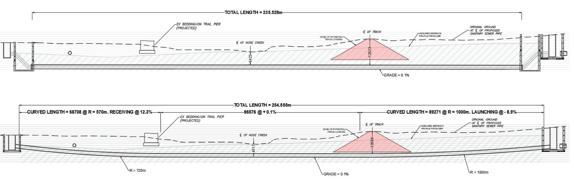
Figure 2: Siphon initial design (top) versus W&B design (bottom)
W&B would then break out the new base and excavate the 21 ft (6.6 m) of backfill to launch the Nose Creek siphon crossing from the lower level.
For the third option W&B considered installing two caisson shafts adjacent to each other, one for each drive. The shaft for the main drive would be sunk 40 ft (12 m) deep and the shaft for the siphon crossing would need to be sunk 61 ft (18.6 m).
All three of these options had various problems. Options 1 and 2 required an enormous shaft size to be able to fit the required pipework to raise the siphon crossing 21 ft (6.6 m) and a considerable amount of work inside the shaft once the main drive was complete. Option 3 was more desirable than options 1 and 2, however it involved the time, work, and cost of installing two full shafts.
W&B had previous experience installing vertical curves in microtunnel drives and believed this project would benefit from installing one for the siphon crossing. By introducing a vertical curve W&B were able to launch and retrieve the machine at the required inverts eliminating the need for larger or deeper caisson shafts. The use of the closed face microtunnelling method and ASTM C76 Class V Reinforced Concrete Pipe (RCP) allowed W&B to reduce the depth by 6 ft (2 m) while still maintaining the minimal track settlement values predicted by Jacobs. This raising of the pipe reduced the hydraulic head losses through the siphon in additional to the head losses eliminated due to the removal of the four 45-degree bends. With respect to the maintenance and inspection of the siphon, access is via a 12-percent downward gradient in lieu of a 50-percent gradient, as shown in Figure 2.
In addition to curving the siphon alignment, W&B sought to revise the tunnel pipe material. The initial design called for 60-in (1,500-mm) fiberglass reinforced pipe installed within a steel liner plate and short section of steel casing under the CPKC ROW. W&B proposed to install an HDPE-lined reinforced concrete pipe (RCP) as the carrier pipe in a single pass installation. CPKC agreed that lined RCP was acceptable for installation as a carrier pipe in a single pass installation without the need for a permanent casing. W&B launched the MTBM on November 6th, 2024 and retrieved the machine on December 7, 2024 completing the 836-ft (255-m) curved microtunnel drive. The drive included two vertical curves ranging from 2,300 ft (700 m) to 3,300 ft (1,000 m) in radius.
CONCLUSIONS
The Nose Creek Phase B (Contract 4) project is on track for completion before the forecasted sanitary sewer trunk capacity is needed and within the estimated construction budget. Primary design challenges were associated with the deep installation necessitated by the gravity nature of the flow, the potential to destabilize the adjacent hillsides, and the permitting process for a highly skewed crossing of the CPKC tracks. Construction challenges were successfully addressed by a highly skilled contractor selected using a twostage procurement process that emphasized experience and teamwork.
The innovation brought to the construction by W&B resulted in a reduced construction footprint and enhanced hydraulics and future access for maintenance. Submittals and proposed design modifications were well documented and thorough, which sped review and acceptance. The microtunnelling was completed without any frac outs, and observed settlement was within the baseline limits. The resulting main tunnel is the longest single-drive pipe jack in North America and a world-wide record for pipe jacking in this diameter range according to the MTBM manufacturer Herrenknecht.
REFERENCES
Heuer, R.E. 1995. Estimating Rock Tunnel Water Inflow, Rapid Excavation and Tunneling Conference Proceedings. Heuer, R.E., 2005. Estimated Rock Tunnel Water Inflow – II, Rapid Excavation and Tunneling Conference Proceedings.
MicroFEM. 2008. MLU for Windows, version 1.51, Aquifer Test Analysis for Unsteady State Flow in Multiple Aquifer Systems. http://www.microfem. com/products/mlu.html. Accessed October 1, 2009.
MicroFEM. 2013. MicroFEM for Windows, version 4.10.55, Aquifer Test Analysis for Unsteady State Flow in Multiple Aquifer Systems.
Thurber Engineering Ltd. (Thurber). 2009. Preliminary Geotechnical Assessment, Nose Creek Sanitary Sewer Trunk Upgrades, 32 Avenue to 144 Avenue N.E. Calgary, Alberta, Canada. May.
Thurber Engineering Ltd. (Thurber). 2011. Geotechnical Investigation, Nose Creek Sanitary Trunk Upgrade, Beddington Trail to 32 Avenue NE. Calgary, Alberta, Canada. January.
Thurber Engineering Ltd. (Thurber). 2014a. Slope Stability Assessment, Nose Creek Sanitary Trunk From 64 Avenue NE Beddington Trail. Calgary, Alberta, Canada. October.
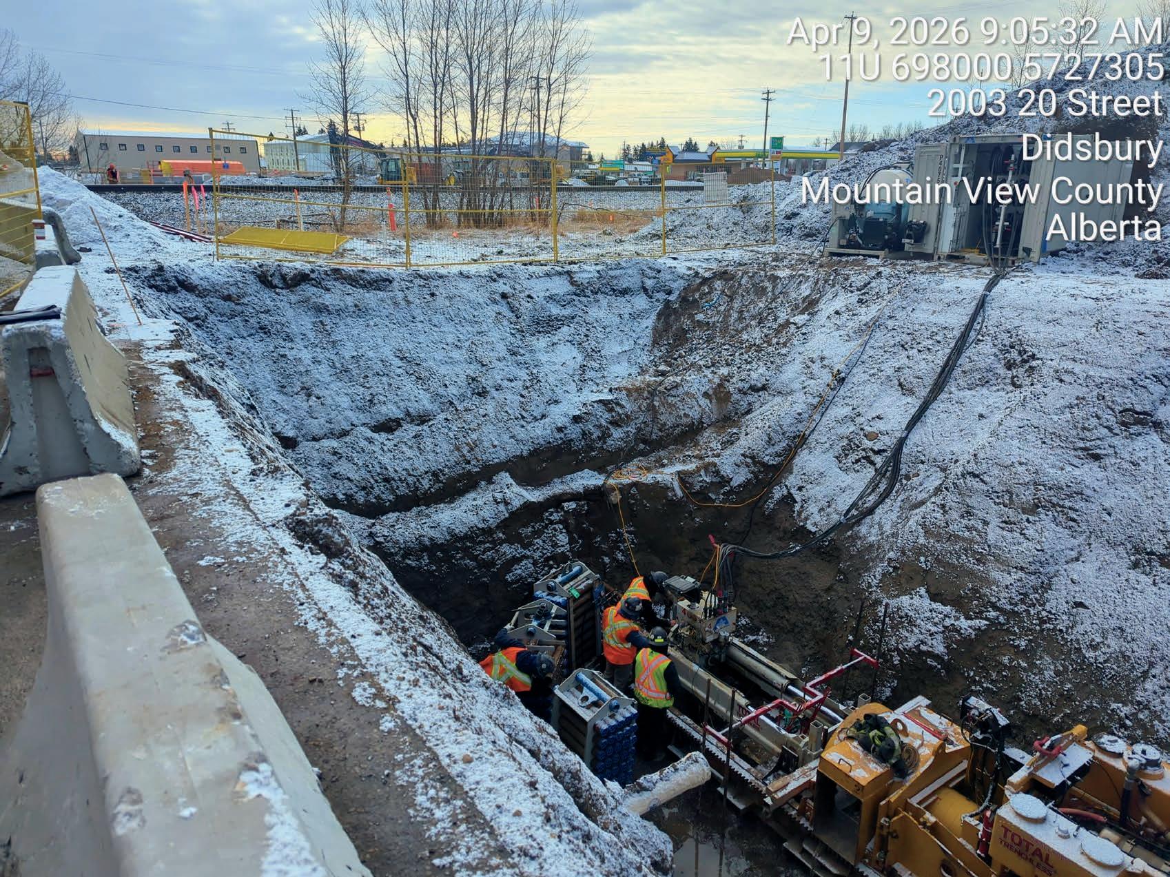
Thurber Engineering Ltd. (Thurber). 2014b. Supplementary Geophysics and Pump Testing Program (Draft), Nose Creek Sanitary Trunk Upgrade Project, Proposed Tunnel Crossing at Beddington Trail. Calgary, Alberta, Canada. February.


ADVERTISER PRODUCT & SERVICE CENTRE
The NW Trenchless Journal is made possible by the companies below who convey their important messages on our pages. We thank them for their support of NASTT-NW and its publication and encourage you to contact them when making your purchasing decisions. To make it easier to contact these companies, we have included the page number of their advertisement, their phone number, and, where applicable, their website.
VIEW US ONLINE NASTT-NW.COM
HOW DOES NO DIG POINT REPAIR WORK?
Instead of digging up the entire sewer line our non-destructive No Dig sewer line point repairs are done by accessing the damaged pipe through manhole locations. Our repair sleeve is inserted into the pipe directly from the manhole and delivered to the damaged section of pipe. The sleeve is then expanded by our inflatable packer and compressed against the inner pipe wall where it is permanently locked into position.
We utilize the QuickLock point repair system which can be used on pipe diameters of 6” to 30” and repair the following defects:
• Infiltrations
• Offset joints
• Abandoned laterals
• Root intrusions
• Holes
• Longitudinal & circumferential cracks
• Restore structural integrity of pipe
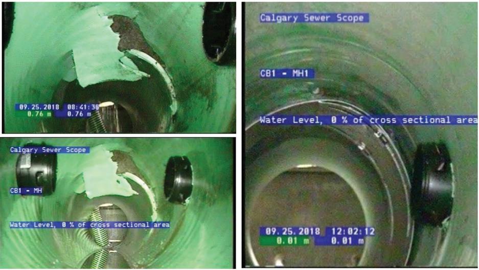

403-536-1415 | calgarysewerscope.ca info@calgarysewerscope.ca
Go Trenchless with PVC™
Engineered for Horizontal Directional Drilling (HDD) and other trenchless applications, TerraBrute® CR is a 100% non-metallic, AWWA C900 PVC pressure pipe system. Non-corroding and installation-friendly, TerraBrute® CR lets you standardize on PVC throughout your municipal water infrastructure. Designed for large diameter projects up to 24 inches, it offers unmatched strength and leak-free performance in high-pressure environments, ensuring efficient, cost-effective solutions with minimal disruption.


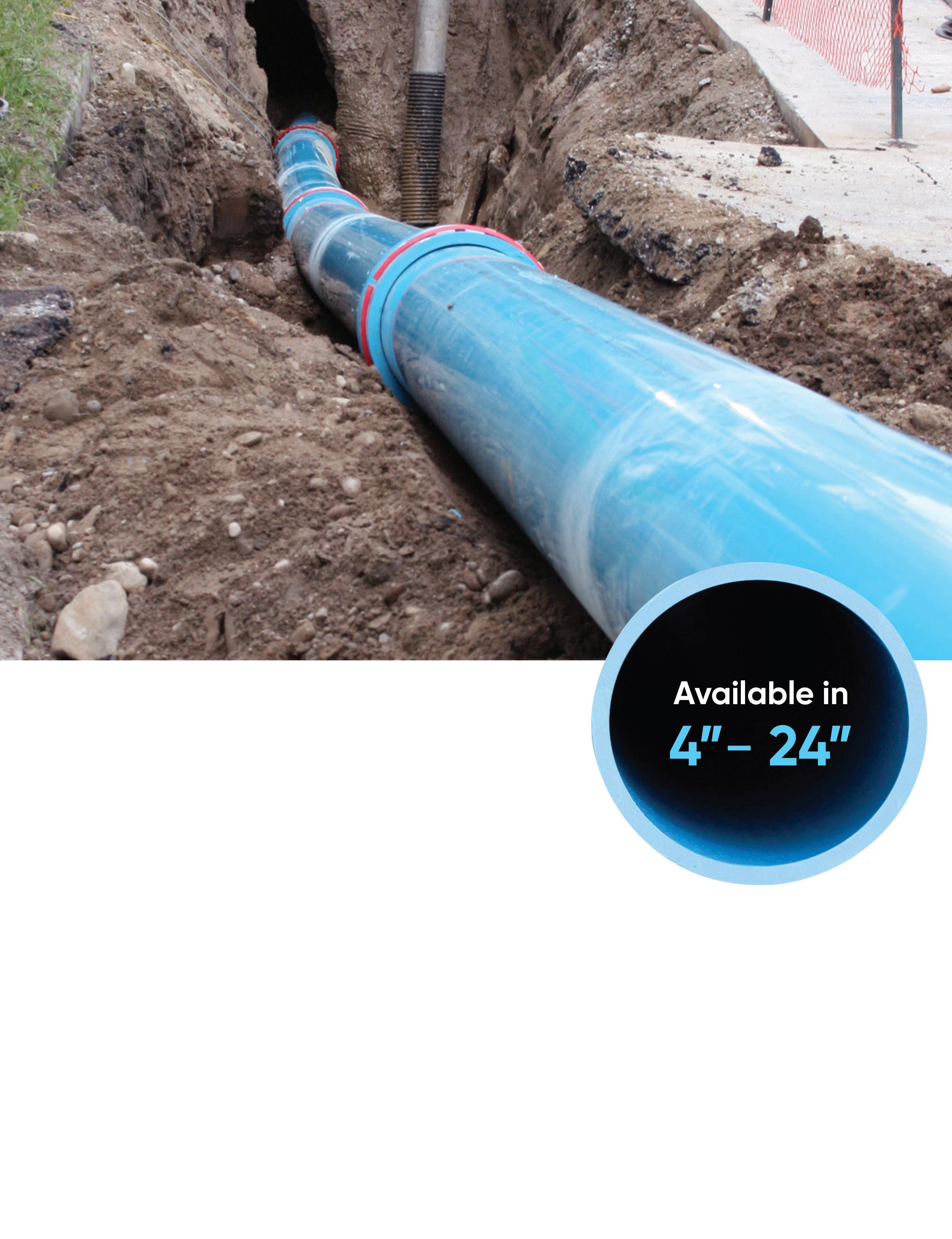
Above. Beyond. Below.
Civil Construction
Energy & Renewables
Engineering & Design
Water & Wastewater
Mission Critical