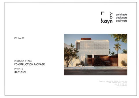
VILLA 82
// DESIGN STAGE
CONSTRUCTION PACKAGE /// DATE
JULY 2023
2
1
3
4
5
A
B
C
D
E
GENERAL NOTES:
LEGEND:
1. Do not scale from this drawing 2. All setting out and check dimensions are to be verified by the contractor on site. Upon receipt of this drawing, any discrepancies are to be reported to the Architect/Supervising Officer immediately. 3. The positions of all existing services are to be verified by the contractor on site. 4. Where applicable, all dimensions of existing buildings are to be verified on site. Structural grid dimensions, where indicated, are nominal. Where applicable, the actual position of installed structure on site may deviate from the nominal grid. 5. This drawing is to be read in conjunction with the appropriate Architects and Consultants drawings and specification. 6. All works to be carried out in accordance with current Health and Safety Regulations.
F
REVISION:
CONCEPT DESIGN PHASE
05
SCHEMATIC DESIGN PHASE
04
DESIGN DEVELOPMENT PHASE
03
CONSTRUCTION DRAWINGS PHASE
02 01
DESIGN CONCEPT
DAYMONTHYEAR
NO. DESCRIPTION
DATE DRAWING TITLE
OMAR ALSAIF
OWNER
ISSUE DATE
MAY 2023
PRIVATE VILLA
PROJECT
AL-RIYADH
LOCATION
DRAWN BY:
DESIGNED BY:
ARCH. MARYAM
ARCH. DINA HADDADIN
PAPER SIZE
A1 1
LIST OF DRAWINGS
2
3
4
5
SCALE
PROJECT No
SHEET No
-
KSA22-02 A-01-001
2
1
3
ABBREVIATIONS (A) A AC, A/C ACCU ADJ AG AHU ALUM
A
- AREA, ARCHITECTURE - AIR CONDITION - AIR COOLED CONDENSING UNIT - ADJACENT - AIR GAB - AIR HANDLING UNIT - ALUMINUM
(B) BLDG. - BUILDING BLK - BLOCK BM - BENCHMARK BO - BOTTOM OF BOT, BOTT - BOTTOM BRD. - BOARD
B
(H)
(R)
H,HT.,HGT. - HEIGHT HARDNR - HARDENER HB - HOSE BIB HD - HAND DRYER HDW. - HARDWARE HOR. - HORIZONTAL HR. - HOUR HVAC - HEATING VENTILATION AIR CONDITION HW - HARDWOOD HP - HIGHEST POINT
R RAC RC RD REF.
(I) ID IE. INCL'D INFO. INT.
(J)
CAB. CAP. CATV
JAN. JT.
- JANITOR - JOINT
(K) KG. KIT. KS
- KILOGRAM - KITCHEN - KITCHEN SINK
(L) LAB. LAM. LAND'G LEV. LOAD'G LP LSD
- LABORATORY - LAMINATED - LANDING - LEVEL - LOADING - LOWEST POINT - LIQUID SOAP DISPENSER
C
- DRYER - DECORATIVE - DETAIL - DRINKING FOUNTAIN - DIAMETER - DIMENSION - DOOR LOCK - DOWN - DOORS - DOWN SPOUT - DRAWING
(E) E EA. EF EL, ELEV.
- EAST - EACH - EXHAUST FAN - ELEVATION, ELEVATOR ELEC, ELECT - ELECTRIC, ELECTRICAL EQ. - EQUAL, EQUATES EQUIPT. - EQUIPMENT ERB - ELECTRIC RISING BARRIER EWC - EASTERN WATER CLOSET EWH - ELECTRIC WATER HEATER EXAM. - EXAMINATION EXH. - EXHAUST EX. JT. - EXPANSION JOINT EXP. - EXPANDED EXT. - EXTERIOR, EXTERNAL
D
(M) M. MACH. MAINT. MAT. MAX. MECH. MET.
- METER - MACHINE - MAINTENANCE - MATERIAL - MAXIMUM - MECHANICAL - METAL
MFG. MFTR. MH MIN. MISC. MM. MO MTD. MTG.
- MANUFACTURING - MANUFACTURER - MANHOLE - MINIMUM - MISCELLANEOUS - MILLIMETER - MASONRY OPENING - MOUNTED - MOUNTING
N/A NIC NO. NTS.
- NOT APPLICABLE - NOT IN CONTRACT - NUMBER - NOT TO SCALE
(G) GALV. GB GD GEN. G.I. GRC
- GALVANIZED - GRAB BAR - GUTTER DRAIN - GENERAL, GENERATOR - GALVANIZED IRON - GLASS REINFORCED CONCRETE GRD.,GRND.- GROUND GRG - GLASS REINFORCED GYPSUM GWB - GYPSUM WALL BOARD GYP. - GYPSUM
E
S
- SOUTH
SCHED. SD SECT. SH SHT. SIM. SLP.
- SCHEDULE - SOAP DISH - SECTION - SOAP HOLDER - SHEET - SIMILAR - SLOPE
SPECS. - SPECIFICATIONS SQ. - SQUARE SS - SERVICE SINK ST. STL., SST.- STAINLESS STEEL STD. - STANDARD STL. - STEEL STNLS - STAINLESS STO., STORE- STORAGE STP - SEWAGE TREATMENT PLANT STRUCT, - STRUCTURAL STRUCT'L SUSP., SUSP'D - SUSPENDED SYMM. - SYMMETRICAL SYS. - SYSTEM
US
- UNLESS OTHERWISE NOTED - UNDERSIDE
(O) OC OD OPNG ORIG.
X1
1 A
WIRE MESH MATCH LINE
XA
(V) VAR. VER. VERT. VTR
MARBLE (SECTION) - VARIES - VERIFY - VERTICAL - VENT THRU ROOF
ORTHO GRID
GRID AT (14) ANGLE
T TB TF THK. TO TOI., TOIL TOSS TYP.
GRID LINES, COLUMN LINES
(W)
WOOD BLOCKING DRAWING TITLE
W WAIT'G WC WD WDO. WH WP
- WEST, WITH, WIDTH - WAITING - WATER CLOSET - WOOD - WINDOW - WEEP HOLE - WORKING POINT
OTHERS: & < CL Ø @ # %
THERMAL INSULATION (LOOSE)
1
FLOOR PLAN
A 03
SCALE
DISCIPLINE IDENTIFICATION
SCALE USED
A = ARCHITECTURAL S = STRUCTURAL M = MECHANICAL P = PLUMBING E = ELECTRICAL
FIBER GLASS
DRAWING NO. (OR SHEET NO.)
MAIN TITLE
GRAVEL
- AND - ANGLE - CENTER LINE - DIAMETER - EACH, AT - NUMBER - PERCENT - SQUARE
1:100
DETAIL NUMBERING
CD000 REFLECT POOL AREA TO BE TYPICAL VERTICAL DETAILS FOR ( WALL TYPES / FLOORS )
INSULATION (RIGID)
TITLE NUMBERING
DET A100 DRAWING NO.
ACOUSTICAL TILE (LARGE SCALE) - TREAD - TOWEL BAR - TRANSFER FAN - THICK - TOP OF - TOILET - TOP OF STRUCTURAL SLAB - TYPICAL
AREA TO BE DETAILED HORIZONTALLY
EARTH
DETAIL NUMBERING
CD200 AREA TO BE DETAILED VERTICALLY
STRUCTURAL STEEL
LOCATING CONDITION DETAILED STEEL CATWALKS SECTION IDENTIFICATION (TO BE SHOWN ON THE OTHER SHEET OR ON THE SAME SHEET DRAWN)
DRAWINGS NUMBER
PAINTED PLASTER 2 A 08 STONE FOR LONGER SECTIONING
SECTION CUT
A 000
HOLLOW CEMENT CONCRETE BLOCK
GENERAL NOTES ARCHITECTURAL
2 A 08
DRAWING NO. (OR SHEET NO.)
DISCIPLINE IDENTIFICATION
DISCIPLINE IDENTIFICATION
SECTION IDENTIFICATION (TO BE SHOWN ON THE OTHER SHEET OR ON THE SAME SHEET DRAWN)
A 111a
PLANS
ARCHITECTURAL
SOLID CEMENT BLOCK DRAWING NO. (OR SHEET NO.)
WALL SECTION
PABX
ARCHITECTURAL
2 A08
DISCIPLINE IDENTIFICATION
A 200 COLUMN
ELEVATION & SECTION
(P) - PRIVATE AUTOMATIC BRANCH EXCHANGE PAC - PACKAGE AIR CONDITIONER PEJ - PRE MOLDED EXPANSION JOINT PLAS, PLAST - PLASTER PR. - PAIR PROJ. - PROJECT PS - PERENNIAL SPRAY PT. - POINT PTD. - PAPER TOWEL DISPENSING PVC - POLYVINYL CHLORIDE
GRID AT (26) ANGLE
WOOD FINISH (PLAN)
ANNOTATION
- ON CENTERS - OUTSIDE DIAMETER - OPENING - ORIGINAL
Y1
HIDDEN LINE
YA
(T)
ARCHITECTURAL
- FLOOR DRAIN - FINISH FLOOR LEVEL - FINISH GRADE LEVEL - FINISH - FLOOR - FACIAL MIRROR - FREEZER - FOOTING
UON
PERFORATED MESH
FLOOR LEVEL ZONE
(F) FD FFL. FGL. FIN. FL, FLR. FM FRZR FTG.
(U)
TITLE NUMBERING
A = ARCHITECTURAL S = STRUCTURAL M = MECHANICAL P = PLUMBING E = ELECTRICAL
(N)
LEGEND & SYMBOLS CENTER LINE
- RADIUS - ROOM AIR CONDITIONER - REINFORCED CONCRETE - ROOF DRAIN - REFERENCE REFRIGERATOR REINF. - REINFORCED REQ'D - REQUIRED RM. - ROOM RO - ROUGH OPENING RTG. - RATING
(S) - INSIDE DIAMETER, INTERIOR DESIGN - EXAMPLE - INCLUDED - INFORMATION - INTERIOR
(D) D DECO DET. DF DIA. DIM. DL DN. DRS DS DWG.
5
MATERIAL SYMBOLS
(C) - CABINET - CAPITAL - CABLE ANTENNA TELEVISION CEIL, CEIL'G- CEILING CEM. - CEMENT CF - CEILING FAN CH - CLOTHES HOOK CHB - CONCRETE HALLOW BLOCK CL - CENTER LINE CLO. - CLEAR CMU - CONCRETE MASONRY UNIT CO. - CLEAN OUT COL - COLOR, COLUMN CONC. - CONCRETE CONT. - CONTINUOUS CORR. - CORRIDOR, CORRUGATED CWR - COLD WATER RISER
4
FOR SHORTER SECTIONING
SECTION CUT
A 250
REINFORCED CONCRETE WALL
A 300
REVISION NUMBER
2
STAIRCASE & ELEVATOR ARCHITECTURAL
ACOUSTICAL ISOLATION PADS AS SPECS.
A 400
BUILDING NAME
S Q2 67
FURNITURE ARCHITECTURAL
FLOOR
A 500
HEIGHT BUILDING NAME
A 600
+2.25 S-Q2-65
WINDOW NO.
A 700
-4.55
W18 -5.15
WATER PROOF MEMBRANE
CONSTRUCTION DETAILS ARCHITECTURAL
ROOM NO.
DOOR IDENTIFICATION
FLOOR
GLASS (SMALL SCALE)
TOILETS & KITCHEN LAYOUTS ARCHITECTURAL
ROOM IDENTIFICATION
GLASS (LARGE SCALE)
REFLECTED CEILING ARCHITECTURAL
ROOM NO.
LINTEL
WINDOW IDENTIFICATION
SILL
LINTEL
A 800
-3.10 -5.30
COMPRESSIBLE MATERIAL AS SPECS.
SILL
OPENING IDENTIFICATION
FINISH FLOOR LEVEL
FINISHING SCHEDULE DOORS & WINDOWS SCHEDULE
GYPSUM BLOCK
+0.00 F.F.L +0.00 S.S.L
LEVEL (IN PLANS)
STRUC. SLAB LEVEL
CARPET
±0.00
LEVEL (IN ELEVATIONS & SECTIONS)
CERAMIC TILE
NOISE CRITERIA LEVEL
NC 25
GENERAL NOTES:
LEGEND:
1. Do not scale from this drawing 2. All setting out and check dimensions are to be verified by the contractor on site. Upon receipt of this drawing, any discrepancies are to be reported to the Architect/Supervising Officer immediately. 3. The positions of all existing services are to be verified by the contractor on site. 4. Where applicable, all dimensions of existing buildings are to be verified on site. Structural grid dimensions, where indicated, are nominal. Where applicable, the actual position of installed structure on site may deviate from the nominal grid. 5. This drawing is to be read in conjunction with the appropriate Architects and Consultants drawings and specification. 6. All works to be carried out in accordance with current Health and Safety Regulations.
F
REVISION:
CONCEPT DESIGN PHASE
05
SCHEMATIC DESIGN PHASE
04
DESIGN DEVELOPMENT PHASE
03
CONSTRUCTION DRAWINGS PHASE
02 01
DESIGN CONCEPT
DAYMONTHYEAR
NO. DESCRIPTION
DATE DRAWING TITLE
OMAR ALSAIF
OWNER
ISSUE DATE
MAY 2023
PRIVATE VILLA
PROJECT
AL-RIYADH
LOCATION
DRAWN BY:
DESIGNED BY:
ARCH. MARYAM
ARCH. DINA HADDADIN
PAPER SIZE
A1 1
ABBREVIATIONS & SYMBOLS
2
3
4
5
SCALE
PROJECT No
SHEET No
-
KSA22-02 A-01-002
2
1
3
4
5
A
B
C
D
E
GENERAL NOTES:
LEGEND:
1. Do not scale from this drawing 2. All setting out and check dimensions are to be verified by the contractor on site. Upon receipt of this drawing, any discrepancies are to be reported to the Architect/Supervising Officer immediately. 3. The positions of all existing services are to be verified by the contractor on site. 4. Where applicable, all dimensions of existing buildings are to be verified on site. Structural grid dimensions, where indicated, are nominal. Where applicable, the actual position of installed structure on site may deviate from the nominal grid. 5. This drawing is to be read in conjunction with the appropriate Architects and Consultants drawings and specification. 6. All works to be carried out in accordance with current Health and Safety Regulations.
F
REVISION:
CONCEPT DESIGN PHASE
05
SCHEMATIC DESIGN PHASE
04
DESIGN DEVELOPMENT PHASE
03
CONSTRUCTION DRAWINGS PHASE
02 01
DESIGN CONCEPT
DAYMONTHYEAR
NO. DESCRIPTION
DATE
-OMAR ALSAIF
OWNER
ISSUE DATE
MAY 2023
PRIVATE VILLA
PROJECT
AL-RIYADH
LOCATION
DRAWN BY:
DESIGNED BY:
ARCH. MARYAM
ARCH. DINA HADDADIN
PAPER SIZE
A1 1
RENDERS
DRAWING TITLE
2
3
4
5
SCALE
PROJECT No
SHEET No
-
KSA22-02 A-02-001
2
1
3
4
5
A
B
C
D
E
GENERAL NOTES:
LEGEND:
1. Do not scale from this drawing 2. All setting out and check dimensions are to be verified by the contractor on site. Upon receipt of this drawing, any discrepancies are to be reported to the Architect/Supervising Officer immediately. 3. The positions of all existing services are to be verified by the contractor on site. 4. Where applicable, all dimensions of existing buildings are to be verified on site. Structural grid dimensions, where indicated, are nominal. Where applicable, the actual position of installed structure on site may deviate from the nominal grid. 5. This drawing is to be read in conjunction with the appropriate Architects and Consultants drawings and specification. 6. All works to be carried out in accordance with current Health and Safety Regulations.
F
REVISION:
CONCEPT DESIGN PHASE
05
SCHEMATIC DESIGN PHASE
04
DESIGN DEVELOPMENT PHASE
03
CONSTRUCTION DRAWINGS PHASE
02 01
DESIGN CONCEPT
DAYMONTHYEAR
NO. DESCRIPTION
DATE
-OMAR ALSAIF
OWNER
ISSUE DATE
MAY 2023
PRIVATE VILLA
PROJECT
AL-RIYADH
LOCATION
DRAWN BY:
DESIGNED BY:
ARCH. MARYAM
ARCH. DINA HADDADIN
PAPER SIZE
A1 1
RENDERS
DRAWING TITLE
2
3
4
5
SCALE
PROJECT No
SHEET No
-
KSA22-02 A-02-002
2
1
3
4
5
A
B
C
D
E
GENERAL NOTES:
LEGEND:
1. Do not scale from this drawing 2. All setting out and check dimensions are to be verified by the contractor on site. Upon receipt of this drawing, any discrepancies are to be reported to the Architect/Supervising Officer immediately. 3. The positions of all existing services are to be verified by the contractor on site. 4. Where applicable, all dimensions of existing buildings are to be verified on site. Structural grid dimensions, where indicated, are nominal. Where applicable, the actual position of installed structure on site may deviate from the nominal grid. 5. This drawing is to be read in conjunction with the appropriate Architects and Consultants drawings and specification. 6. All works to be carried out in accordance with current Health and Safety Regulations.
F
REVISION:
CONCEPT DESIGN PHASE
05
SCHEMATIC DESIGN PHASE
04
DESIGN DEVELOPMENT PHASE
03
CONSTRUCTION DRAWINGS PHASE
02 01
DESIGN CONCEPT
DAYMONTHYEAR
NO. DESCRIPTION
DATE
-OMAR ALSAIF
OWNER
ISSUE DATE
MAY 2023
PRIVATE VILLA
PROJECT
AL-RIYADH
LOCATION
DRAWN BY:
DESIGNED BY:
ARCH. MARYAM
ARCH. DINA HADDADIN
PAPER SIZE
A1 1
RENDERS
DRAWING TITLE
2
3
4
5
SCALE
PROJECT No
SHEET No
-
KSA22-02 A-02-003
2
1
3
4
5
A
B
C
D
E
GENERAL NOTES:
LEGEND:
1. Do not scale from this drawing 2. All setting out and check dimensions are to be verified by the contractor on site. Upon receipt of this drawing, any discrepancies are to be reported to the Architect/Supervising Officer immediately. 3. The positions of all existing services are to be verified by the contractor on site. 4. Where applicable, all dimensions of existing buildings are to be verified on site. Structural grid dimensions, where indicated, are nominal. Where applicable, the actual position of installed structure on site may deviate from the nominal grid. 5. This drawing is to be read in conjunction with the appropriate Architects and Consultants drawings and specification. 6. All works to be carried out in accordance with current Health and Safety Regulations.
F
REVISION:
CONCEPT DESIGN PHASE
05
SCHEMATIC DESIGN PHASE
04
DESIGN DEVELOPMENT PHASE
03
CONSTRUCTION DRAWINGS PHASE
02 01
DESIGN CONCEPT
DAYMONTHYEAR
NO. DESCRIPTION
DATE
-OMAR ALSAIF
OWNER
ISSUE DATE
MAY 2023
PRIVATE VILLA
PROJECT
AL-RIYADH
LOCATION
DRAWN BY:
DESIGNED BY:
ARCH. MARYAM
ARCH. DINA HADDADIN
PAPER SIZE
A1 1
RENDERS
DRAWING TITLE
2
3
4
5
SCALE
PROJECT No
SHEET No
-
KSA22-02 A-02-004
2
1
3
4
5
A
B
C
D
E
GENERAL NOTES:
LEGEND:
1. Do not scale from this drawing 2. All setting out and check dimensions are to be verified by the contractor on site. Upon receipt of this drawing, any discrepancies are to be reported to the Architect/Supervising Officer immediately. 3. The positions of all existing services are to be verified by the contractor on site. 4. Where applicable, all dimensions of existing buildings are to be verified on site. Structural grid dimensions, where indicated, are nominal. Where applicable, the actual position of installed structure on site may deviate from the nominal grid. 5. This drawing is to be read in conjunction with the appropriate Architects and Consultants drawings and specification. 6. All works to be carried out in accordance with current Health and Safety Regulations.
F
REVISION:
CONCEPT DESIGN PHASE
05
SCHEMATIC DESIGN PHASE
04
DESIGN DEVELOPMENT PHASE
03
CONSTRUCTION DRAWINGS PHASE
02 01
DESIGN CONCEPT
DAYMONTHYEAR
NO. DESCRIPTION
DATE
-OMAR ALSAIF
OWNER
ISSUE DATE
MAY 2023
PRIVATE VILLA
PROJECT
AL-RIYADH
LOCATION
DRAWN BY:
DESIGNED BY:
ARCH. MARYAM
ARCH. DINA HADDADIN
PAPER SIZE
A1 1
RENDERS
DRAWING TITLE
2
3
4
5
SCALE
PROJECT No
SHEET No
-
KSA22-02 A-02-005
2
1
3
4
5
A
B
C
D
E
GENERAL NOTES:
LEGEND:
1. Do not scale from this drawing 2. All setting out and check dimensions are to be verified by the contractor on site. Upon receipt of this drawing, any discrepancies are to be reported to the Architect/Supervising Officer immediately. 3. The positions of all existing services are to be verified by the contractor on site. 4. Where applicable, all dimensions of existing buildings are to be verified on site. Structural grid dimensions, where indicated, are nominal. Where applicable, the actual position of installed structure on site may deviate from the nominal grid. 5. This drawing is to be read in conjunction with the appropriate Architects and Consultants drawings and specification. 6. All works to be carried out in accordance with current Health and Safety Regulations.
F
REVISION:
CONCEPT DESIGN PHASE
05
SCHEMATIC DESIGN PHASE
04
DESIGN DEVELOPMENT PHASE
03
CONSTRUCTION DRAWINGS PHASE
02 01
DESIGN CONCEPT
DAYMONTHYEAR
NO. DESCRIPTION
DATE
-OMAR ALSAIF
OWNER
ISSUE DATE
MAY 2023
PRIVATE VILLA
PROJECT
AL-RIYADH
LOCATION
DRAWN BY:
DESIGNED BY:
ARCH. MARYAM
ARCH. DINA HADDADIN
PAPER SIZE
A1 1
RENDERS
DRAWING TITLE
2
3
4
5
SCALE
PROJECT No
SHEET No
-
KSA22-02 A-02-006
2
1
3
4
5
A
B
C
D
E
GENERAL NOTES:
LEGEND:
1. Do not scale from this drawing 2. All setting out and check dimensions are to be verified by the contractor on site. Upon receipt of this drawing, any discrepancies are to be reported to the Architect/Supervising Officer immediately. 3. The positions of all existing services are to be verified by the contractor on site. 4. Where applicable, all dimensions of existing buildings are to be verified on site. Structural grid dimensions, where indicated, are nominal. Where applicable, the actual position of installed structure on site may deviate from the nominal grid. 5. This drawing is to be read in conjunction with the appropriate Architects and Consultants drawings and specification. 6. All works to be carried out in accordance with current Health and Safety Regulations.
F
REVISION:
CONCEPT DESIGN PHASE
05
SCHEMATIC DESIGN PHASE
04
DESIGN DEVELOPMENT PHASE
03
CONSTRUCTION DRAWINGS PHASE
02 01
DESIGN CONCEPT
DAYMONTHYEAR
NO. DESCRIPTION
DATE
-OMAR ALSAIF
OWNER
ISSUE DATE
MAY 2023
PRIVATE VILLA
PROJECT
AL-RIYADH
LOCATION
DRAWN BY:
DESIGNED BY:
ARCH. MARYAM
ARCH. DINA HADDADIN
PAPER SIZE
A1 1
RENDERS
DRAWING TITLE
2
3
4
5
SCALE
PROJECT No
SHEET No
-
KSA22-02 A-02-007
2
1
3
4
5
A
B
C
D
E
GENERAL NOTES:
LEGEND:
1. Do not scale from this drawing 2. All setting out and check dimensions are to be verified by the contractor on site. Upon receipt of this drawing, any discrepancies are to be reported to the Architect/Supervising Officer immediately. 3. The positions of all existing services are to be verified by the contractor on site. 4. Where applicable, all dimensions of existing buildings are to be verified on site. Structural grid dimensions, where indicated, are nominal. Where applicable, the actual position of installed structure on site may deviate from the nominal grid. 5. This drawing is to be read in conjunction with the appropriate Architects and Consultants drawings and specification. 6. All works to be carried out in accordance with current Health and Safety Regulations.
F
REVISION:
CONCEPT DESIGN PHASE
05
SCHEMATIC DESIGN PHASE
04
DESIGN DEVELOPMENT PHASE
03
CONSTRUCTION DRAWINGS PHASE
02 01
DESIGN CONCEPT
DAYMONTHYEAR
NO. DESCRIPTION
DATE
-OMAR ALSAIF
OWNER
ISSUE DATE
MAY 2023
PRIVATE VILLA
PROJECT
AL-RIYADH
LOCATION
DRAWN BY:
DESIGNED BY:
ARCH. MARYAM
ARCH. DINA HADDADIN
PAPER SIZE
A1 1
RENDERS
DRAWING TITLE
2
3
4
5
SCALE
PROJECT No
SHEET No
-
KSA22-02 A-02-008
2
1
3
4
5
A
B
C
D
E
GENERAL NOTES:
LEGEND:
1. Do not scale from this drawing 2. All setting out and check dimensions are to be verified by the contractor on site. Upon receipt of this drawing, any discrepancies are to be reported to the Architect/Supervising Officer immediately. 3. The positions of all existing services are to be verified by the contractor on site. 4. Where applicable, all dimensions of existing buildings are to be verified on site. Structural grid dimensions, where indicated, are nominal. Where applicable, the actual position of installed structure on site may deviate from the nominal grid. 5. This drawing is to be read in conjunction with the appropriate Architects and Consultants drawings and specification. 6. All works to be carried out in accordance with current Health and Safety Regulations.
F
REVISION:
CONCEPT DESIGN PHASE
05
SCHEMATIC DESIGN PHASE
04
DESIGN DEVELOPMENT PHASE
03
CONSTRUCTION DRAWINGS PHASE
02 01
DESIGN CONCEPT
DAYMONTHYEAR
NO. DESCRIPTION
DATE
-OMAR ALSAIF
OWNER
ISSUE DATE
MAY 2023
PRIVATE VILLA
PROJECT
AL-RIYADH
LOCATION
DRAWN BY:
DESIGNED BY:
ARCH. MARYAM
ARCH. DINA HADDADIN
PAPER SIZE
A1 1
RENDERS
DRAWING TITLE
2
3
4
5
SCALE
PROJECT No
SHEET No
-
KSA22-02 A-02-009
2
1
3
4
5
A
B
C
D
E
GENERAL NOTES:
LEGEND:
1. Do not scale from this drawing 2. All setting out and check dimensions are to be verified by the contractor on site. Upon receipt of this drawing, any discrepancies are to be reported to the Architect/Supervising Officer immediately. 3. The positions of all existing services are to be verified by the contractor on site. 4. Where applicable, all dimensions of existing buildings are to be verified on site. Structural grid dimensions, where indicated, are nominal. Where applicable, the actual position of installed structure on site may deviate from the nominal grid. 5. This drawing is to be read in conjunction with the appropriate Architects and Consultants drawings and specification. 6. All works to be carried out in accordance with current Health and Safety Regulations.
F
REVISION:
CONCEPT DESIGN PHASE
05
SCHEMATIC DESIGN PHASE
04
DESIGN DEVELOPMENT PHASE
03
CONSTRUCTION DRAWINGS PHASE
02 01
DESIGN CONCEPT
DAYMONTHYEAR
NO. DESCRIPTION
DATE
-OMAR ALSAIF
OWNER
ISSUE DATE
MAY 2023
PRIVATE VILLA
PROJECT
AL-RIYADH
LOCATION
DRAWN BY:
DESIGNED BY:
ARCH. MARYAM
ARCH. DINA HADDADIN
PAPER SIZE
A1 1
RENDERS
DRAWING TITLE
2
3
4
5
SCALE
PROJECT No
SHEET No
-
KSA22-02 A-02-010
2
1
3
4
5
A PLOT
N
E:668008.421 N:2752154.114
E:667981.326 N:2752141.235
I MI T 117
188
185
185
355
382
48
167
335
127
495
210
P
L OT
L
170
L OT
I MI
SKYLIGHT
OPEN TO SKY
130
T
B AC
RWO
T
+10
RWO
RWO
T.O.P +12.27
143
T.O.P + 9.84
F.F.L+11.67 S.S.L+11.42
S
35
F.F.L 3.10 S.S.L 2.85
122
E
+10
RWO
80
L I NE
B
E
S
K
K
B AC
P
RWO +10
L I NE
30
SEATING AREA
+5 RWO
F.F.L -0.15 S.S.L -0.30
T
L
+12
235
RWO +10 +8
+10
MAIN ENTRANCE
RWO
RWO
LADDER
PLOT +10
295
F.F.L + 7.79 S.S.L + 7.54
OPEN TO OPEN TO SKY SKY
OPEN TO SKY
OPEN TO SKY
T.O.S S.S.L +4.70 45
+10
S
RWO
E
+10
T
L I NE
+10
T
B AC
MI
L
L
MI
OPEN TO SKY
130
T
B AC
S
RWO
T
RWO
T.O.P +12.27
143
RWO
F.F.L+11.67 S.S.L+11.42
S
35
F.F.L 3.10 S.S.L 2.85
122
E
+10
T.O.P + 9.84
80
+10
RWO
30
SEATING AREA
+5 RWO
F.F.L -0.15 S.S.L -0.30
+12
RWO
235
D
E
L I NE
B AC
P
K
T
RWO +10
L I NE
K
MAIN ROAD (15 M)
E
L I NE RWO
P
STREET LEVEL 671.25 670.60
K
K
S RWO
T
B AC
T.O.P + 8.70
230
C
130
GARAGE ENTRANCE
+10 +8
+10
MAIN ENTRANCE
RWO
RWO
STREET LEVEL 670.90
LADDER
PLOT +10
295
F.F.L + 7.79 S.S.L + 7.54
OPEN TO OPEN TO SKY SKY
OPEN TO SKY
OPEN TO SKY
T.O.S S.S.L +4.70 45
+10
S
RWO
E
+10
130
GARAGE ENTRANCE
T
E
L I NE
T
B AC I MI
L OT
L
SKYLIGHT
T
P
I MI
L OT
E:667987.765 N:2752127.687
L
E
RWO
P
STREET LEVEL 670.60
K
K
S RWO
T
230
L I NE
+10
B AC
T.O.P + 8.70
E:668021.300 N:2752127.019
PLOT
GENERAL NOTES:
LEGEND:
1. Do not scale from this drawing 2. All setting out and check dimensions are to be verified by the contractor on site. Upon receipt of this drawing, any discrepancies are to be reported to the Architect/Supervising Officer immediately. 3. The positions of all existing services are to be verified by the contractor on site. 4. Where applicable, all dimensions of existing buildings are to be verified on site. Structural grid dimensions, where indicated, are nominal. Where applicable, the actual position of installed structure on site may deviate from the nominal grid. 5. This drawing is to be read in conjunction with the appropriate Architects and Consultants drawings and specification. 6. All works to be carried out in accordance with current Health and Safety Regulations.
F
REVISION:
CONCEPT DESIGN PHASE
05
SCHEMATIC DESIGN PHASE
04
DESIGN DEVELOPMENT PHASE
03
CONSTRUCTION DRAWINGS PHASE
02 01
DESIGN CONCEPT
DAYMONTHYEAR
NO. DESCRIPTION
DATE DRAWING TITLE
OMAR ALSAIF
OWNER
ISSUE DATE
MAY 2023
PRIVATE VILLA
PROJECT
AL-RIYADH
LOCATION
1
GENERAL SITE PLAN
2
3
4
5
DRAWN BY:
DESIGNED BY:
ARCH. MARYAM
ARCH. DINA HADDADIN
PAPER SIZE
SCALE
PROJECT No
SHEET No
A1
1:100
KSA22-02 A-03-001
2
1
3
4
5
N
A
E:668008.421 N:2752154.114
E:667981.326 N:2752141.235
240
2560
T
I MI L
117
110
185 480
188
185
355
382
48
167
1970
335
127
495
P
210
L OT L
170
200
RWO +10
T
200
130
B AC
L I NE
B AC
E
OPEN TO SKY
T
E
+10
80
P
K
SKYLIGHT
K
B
+10
L I NE
RWO
S
L OT 200
ELEC.
T.V.SCREEN
FIRE PLACE
T
F.F.L -0.15 S.S.L -0.30
I MI
SKYLIGHT
RWO F.F.L +0.00 S.S.L -0.15
GROUND FLOOR
615
12
11
10
7
8
15
17
3
T.V.SCREEN 2
F.F.L+11.69 S.S.L+11.42
18
+5
5
4
16 F.F.L + 7.84 SECOND FLOOR OPEN TO ABOVE S.S.L + 7.69
TOP OF ROOF
SEATING AREA
6
460
F.F.L+11.67 S.S.L+11.42
OPEN TO ABOVE
9
F.F.L + 4.00 S.S.L +3.82
14
FIRST FLOOR
F.F.L 0.00 S.S.L -0.15
T.V.SCREEN
GUARD ROOM F.F.L 3.10 S.S.L 2.85 F.F.L -0.15 S.S.L -0.30
13
122
T.O.P GUEST ROOM +12.27
143
RWO
1
35
T.O.P + 9.84
19
30
S
RWO
LIVING ROOM 20
RWO
21
22
23
24
25
FIRE PLACE
+12
DINING ROOM
F.F.L -0.30 S.S.L -0.45
GUESTS ENTRANCE +10
MAIN ENTRANCE
+8
+10 RWO
1100
RWO
LADDER
1100
F.F.L 0.00 S.S.L RWO -0.15
185
F.F.L -0.15 S.S.L -0.30
235
C
+10 F.F.L + 7.79 S.S.L + 7.54 295
OPEN TO SKY
STREET LEVEL -0.45
OPEN TO SKY OUTDOOR SITTING AREA
T.O.P + 8.70
T.O.S S.S.L +4.70
F.F.L -0.05 S.S.L -0.20
SHOW KITCHEN +10
455
485
F.F.L -0.15 S.S.L -0.30
SLOPE 4%
45
D
FAMILY ENTRANCE
OPEN TO SKY
6
GARAGE ENTRANCE
SERVICES ENTRANCE
S
4
RWO
+10
E
3
2
+10
E
L I NE RWO
T
B AC
L
SKYLIGHT
T
P
L OT
240
1370
1080 2560
E:667987.765 N:2752127.687
GENERAL NOTES:
200
E:668021.300 N:2752127.019
LEGEND:
1. Do not scale from this drawing 2. All setting out and check dimensions are to be verified by the contractor on site. Upon receipt of this drawing, any discrepancies are to be reported to the Architect/Supervising Officer immediately. 3. The positions of all existing services are to be verified by the contractor on site. 4. Where applicable, all dimensions of existing buildings are to be verified on site. Structural grid dimensions, where indicated, are nominal. Where applicable, the actual position of installed structure on site may deviate from the nominal grid. 5. This drawing is to be read in conjunction with the appropriate Architects and Consultants drawings and specification. 6. All works to be carried out in accordance with current Health and Safety Regulations.
F
I MI
110
REVISION:
CONCEPT DESIGN PHASE
05
SCHEMATIC DESIGN PHASE
04
DESIGN DEVELOPMENT PHASE
03
CONSTRUCTION DRAWINGS PHASE
02 01
DESIGN CONCEPT
DAYMONTHYEAR
NO. DESCRIPTION
DATE DRAWING TITLE
OMAR ALSAIF
OWNER
SETTING OUT PLAN
ISSUE DATE
MAY 2023
PRIVATE VILLA
PROJECT
AL-RIYADH
LOCATION
1
L
E
L OT
I MI
P
RWO
T
F.F.L 3.10 S.S.L 2.85
K
K
SWIMMING POOL
BBQ AREA
200
1
230
SKYLIGHT
BACK KITCHEN
B AC
L I NE
T
T.O.P STORAGE + 8.70
S
200
130
5
2
3
4
5
DRAWN BY:
DESIGNED BY:
ARCH. MARYAM
ARCH. DINA HADDADIN
PAPER SIZE
SCALE
PROJECT No
SHEET No
A1
1:50
KSA22-02 A-03-002
2
1
3
4
5
N
A
E:668008.421 N:2752154.114
E:667981.326 N:2752141.235 3000
T
I MI L
2560 188
117
185
185
355
382
48
167
335
200 210
495
35
L OT
I MI
1970
RWO
130
S
258
222
B AC
T
L I NE
T
40
40
40
+10
+10 1890
420
9
8
7
6
5
15
4
3
OPEN TO ABOVE
T.V.SCREEN
17
2
18
1
19
30
543
615 +5
10
14
16
SEATING AREA
11
122
F.F.L+11.67 S.S.L+11.42
OPEN TO ABOVE
12
35
F.F.L 0.00 S.S.L -0.15
T.V.SCREEN
F.F.L 3.10 S.S.L 2.85 F.F.L -0.15 S.S.L -0.30
13
143
RWO
T.O.P GUEST ROOM +12.27 GUARD ROOM
40
RWO
460
S
RWO
40
T.O.P + 9.84
380
230
E ANNEX BUILDING
LIVING ROOM 20
RWO F.F.L -0.30 S.S.L -0.45
E
OPEN TO SKY 110
200
SKYLIGHT
RWO
80
K
675
K
B AC
+10
L I NE
890
T.V.SCREEN
165
P 200
1235 FIRE PLACE
T
F.F.L -0.15 S.S.L -0.30
B
21
22
23
24
25
FIRE PLACE
+12
DINING ROOM
235
GUESTS ENTRANCE +10
+8 LADDER
40
28
160
680
200
50
182
1100
RWO
1120
28
1020
1100
1100
RWO
105
95
+10
185
MAIN ENTRANCE
1500
F.F.L 0.00 S.S.L RWO -0.15
40
240
F.F.L -0.15 S.S.L -0.30
1500
P
SKYLIGHT
ELEC.
C
127
L
240 170
L OT
50
207
+10 F.F.L + 7.79 S.S.L + 7.54 OPEN TO SKY
317
265
317
STREET LEVEL -0.45
295
0
0 R1
OPEN TO SKY 315 FAMILY ENTRANCE
OPEN TO SKY
T.O.P + 8.70
OUTDOOR SITTING AREA T.O.S S.S.L +4.70
F.F.L -0.05 S.S.L -0.20
SHOW KITCHEN +10
485
40
D
40
455
40
485
296
495
169
271
45
F.F.L -0.15 S.S.L -0.30
SLOPE 4%
465
395
390
50
30
870
210 6
160
SERVICES ENTRANCE
5
S
4
3
80
SWIMMING POOL
L I NE
F.F.L 3.10 S.S.L 2.85
RWO
T
B AC
200
T
2560
I MI
L
SKYLIGHT
240
3000
P
L OT
E:667987.765 N:2752127.687
GENERAL NOTES:
E:668021.300 N:2752127.019
LEGEND:
1. Do not scale from this drawing 2. All setting out and check dimensions are to be verified by the contractor on site. Upon receipt of this drawing, any discrepancies are to be reported to the Architect/Supervising Officer immediately. 3. The positions of all existing services are to be verified by the contractor on site. 4. Where applicable, all dimensions of existing buildings are to be verified on site. Structural grid dimensions, where indicated, are nominal. Where applicable, the actual position of installed structure on site may deviate from the nominal grid. 5. This drawing is to be read in conjunction with the appropriate Architects and Consultants drawings and specification. 6. All works to be carried out in accordance with current Health and Safety Regulations.
F
REVISION:
CONCEPT DESIGN PHASE
05
SCHEMATIC DESIGN PHASE
04
DESIGN DEVELOPMENT PHASE
03
CONSTRUCTION DRAWINGS PHASE
02 01
DESIGN CONCEPT
DAYMONTHYEAR
NO. DESCRIPTION
DATE
SITE PLAN
DRAWING TITLE
DIMENSIONAL PLAN OMAR ALSAIF
OWNER
ISSUE DATE
MAY 2023
PRIVATE VILLA
PROJECT
AL-RIYADH
LOCATION
1
L
E
L OT
I MI
P
RWO
T
1080
BBQ AREA
200
+10
230
40
40
1370
E
K
1
K
110
2
SKYLIGHT
BACK KITCHEN
B AC
L I NE
T
T.O.P STORAGE + 8.70
S
200
1250
E
40
RWO
+10
130
GARAGE ENTRANCE
2
3
4
5
DRAWN BY:
DESIGNED BY:
ARCH. MARYAM
ARCH. DINA HADDADIN
PAPER SIZE
SCALE
PROJECT No
SHEET No
A1
1:50
KSA22-02 A-03-003
2
1
3
4
5
N
A
E:668008.421 N:2752154.114
E:667981.326 N:2752141.235
I MI T
L
170
188
117
185
185
355
382
48
167
335
127
495
122
P
L OT I MI
L OT
L
P
T
S
E
B AC
E
T
80
L I NE
B AC
130
K
T
K
B
L I NE
S
143 122 35 30
C
4*110mm VENTILATION PIPE THROUGH THE WALL AND THE SLAB ALL THE WAY TO THE PLANTER @ 2.0m FROM F.F.L
530
260
620 SUMPIT ACCESS PANEL
SWIMMING POOL SERVICES
272
BALANCE TANK
880
F.F.L -3.45 S.S.L -3.55 TANK ACCESS
D 45 130
S E
320
320
F.F.L -3.45 S.S.L -3.55
F.F.L -1.35 S.S.L -1.45
230
K
E
L I NE
T
K
S
B AC
L I NE
WATER TANK
T
SWIMMING POOL
B AC
500
L
E
L OT
I MI
P
T
T
P
I MI
L OT
GENERAL NOTES:
E:668021.300 N:2752127.019
LEGEND:
1. Do not scale from this drawing 2. All setting out and check dimensions are to be verified by the contractor on site. Upon receipt of this drawing, any discrepancies are to be reported to the Architect/Supervising Officer immediately. 3. The positions of all existing services are to be verified by the contractor on site. 4. Where applicable, all dimensions of existing buildings are to be verified on site. Structural grid dimensions, where indicated, are nominal. Where applicable, the actual position of installed structure on site may deviate from the nominal grid. 5. This drawing is to be read in conjunction with the appropriate Architects and Consultants drawings and specification. 6. All works to be carried out in accordance with current Health and Safety Regulations.
F
REVISION:
CONCEPT DESIGN PHASE
05
SCHEMATIC DESIGN PHASE
04
DESIGN DEVELOPMENT PHASE
03
CONSTRUCTION DRAWINGS PHASE
02 01
DESIGN CONCEPT
DAYMONTHYEAR
NO. DESCRIPTION
DATE DRAWING TITLE
BASEMENT FLOOR DIMENSIONAL PLAN
OMAR ALSAIF
OWNER
ISSUE DATE
MAY 2023
PRIVATE VILLA
PROJECT
AL-RIYADH
LOCATION
1
L
E:667987.765 N:2752127.687
2
3
4
5
DRAWN BY:
DESIGNED BY:
ARCH. MARYAM
ARCH. DINA HADDADIN
PAPER SIZE
SCALE
PROJECT No
SHEET No
A1
1:50
KSA22-02 A-04-100
2
1
3
4
5
N
A
E:668008.421 N:2752154.114
E:667981.326 N:2752141.235
I MI
35
25
210
448 97
100
130
78 100
S 10
57 25
10
293
117
175
25
25
25
190
40
80
100
75
100
100 25
T
20
143
192
117
E
B A C 190
32
25
25
97
185
178
25
25
10
297
80
328
100
20
175
107
10
OPEN TO SKY
410
68
65
75
105
215
190
159
185
25
160 9
8
7
6
270
10
15
122
4
3
OPEN TO ABOVE
18
1
35
2
265
T.V.SCREEN
17
265
472
5
25 50
19
30
163
480
60
149 20
11
456
OPEN TO ABOVE
12
14
235
315
F.F.L 0.00 S.S.L -0.15
317
317
233
13
16
58
250
164
18
10 10
100
T.V.SCREEN
F.F.L -0.15 S.S.L -0.30 120
495
6
917
SKYLIGHT
GUEST ROOM
300
127
35
335
20
25 26 13
25
167
40
225
20
48
E 580
120
103
GUARD ROOM
STORAGE F.F.L -0.15 S.S.L -0.30
903
130
B AC
160 T.V.SCREEN
T.V.SCREEN
20
T
171
25
P 245
105
L 25O T 105
165 100
K
S
103
L I NE
382
L I NE
F.F.L -0.15 S.S.L -0.30
FIRE PLACE
355
25
LIVING ROOM 20
21
22
23
24
235
GUESTS ENTRANCE
290
25
525
25
8
365
25
605
25
55
200
680
20
176
499
207
186
70
20
25
183
70
1500
8
MAIN ENTRANCE
93
F.F.L 0.00 S.S.L -0.15
210
F.F.L -0.15 S.S.L -0.30
165
173
VILLA A
495
243
F.F.L -0.30 S.S.L -0.45
C
FIRE PLACE 186
DINING ROOM
100
25
255
188
T
B
ELEC. 288
185
I MI
F.F.L -0.15 S.S.L -0.30
185
K
GUARD ROOM
188
117
L OT
L
170
263
P
T
L
OPEN TO SKY
267
370
169
100
45
25 90
63
325 288
125
120
100
232
210
53 20
53 20
68 20
1310
58
25
25
415
25
10
25
122
162
265
25
10
T
B AC L
40
185
L OT
20
245
25 250
E
K
SWIMMING POOL
P
20
25
20
2
L I NE
60
BBQ AREA
130
128
S
230
100
4
175
133 10
35
25
3
103
83
L I NE
SKYLIGHT
BACK KITCHEN
733
B AC
S 670
20
STORAGE
362
1
T I MI
60
25
T
10
335
E
185
6
5
90
E
F.F.L -0.05 S.S.L -0.20
25
25
25
25
130
SERVICES ENTRANCE
130
675
GARAGE ENTRANCE
25
F.F.L -0.15 S.S.L -0.30
130
D SLOPE 4%
SHOW KITCHEN
633
130
910
663
OUTDOOR SITTING AREA
K
920
FAMILY ENTRANCE
169
OPEN TO SKY
80
82 477
270
STREET LEVEL -0.45
295
10
15 M STREET
T
P
I MI
L OT GENERAL NOTES:
E:668021.300 N:2752127.019
LEGEND:
1. Do not scale from this drawing 2. All setting out and check dimensions are to be verified by the contractor on site. Upon receipt of this drawing, any discrepancies are to be reported to the Architect/Supervising Officer immediately. 3. The positions of all existing services are to be verified by the contractor on site. 4. Where applicable, all dimensions of existing buildings are to be verified on site. Structural grid dimensions, where indicated, are nominal. Where applicable, the actual position of installed structure on site may deviate from the nominal grid. 5. This drawing is to be read in conjunction with the appropriate Architects and Consultants drawings and specification. 6. All works to be carried out in accordance with current Health and Safety Regulations.
F
REVISION:
CONCEPT DESIGN PHASE
05
SCHEMATIC DESIGN PHASE
04
DESIGN DEVELOPMENT PHASE
03
CONSTRUCTION DRAWINGS PHASE
02 01
DESIGN CONCEPT
DAYMONTHYEAR
NO. DESCRIPTION
DATE DRAWING TITLE
GROUND FLOOR DIMENSIONAL PLAN
OMAR ALSAIF
OWNER
ISSUE DATE
MAY 2023
PRIVATE VILLA
PROJECT
AL-RIYADH
LOCATION
1
L
E:667987.765 N:2752127.687
2
3
4
5
DRAWN BY:
DESIGNED BY:
ARCH. MARYAM
ARCH. DINA HADDADIN
PAPER SIZE
SCALE
PROJECT No
SHEET No
A1
1:50
KSA22-02 A-04-101
2
1
3
4
5
N
A
E:668008.421 N:2752154.114
E:667981.326 N:2752141.235
I MI
P
T
L
188
117
185
185
355
382
48
167
335
495
210
25
112
185
25
18
271
19
26
24 24
25 25
60
25
185
25
25
80 122
615
445
FIRE PLACE
25
RWO 45
145
20 25
110
10
275
235 +8 BEDROOM 01
25
RWO
555
351
LADDER
25
25
189
MINI FRIDGE
WATER COOLER
+10
340
290
290
COFFEE CORNER
295
175
OPEN TO SKY
370
140
SHOW KITCHEN
25
F.F.L -0.05 S.S.L -0.20
T.O.S S.S.L +4.70
45
25
330
75
330
125
OUTDOOR SITTING AREA
T.O.P + 8.70
472
FAMILY ENTRANCE
505
105
105
25
413 SKYLIGHT
BACK KITCHEN
65
882
3
210 85
210
60
10
60
130
50 10
70
2
1
1345
1092
+10
S
SWIMMING POOL
BBQ AREA
200
213
E F.F.L 3.10 S.S.L 2.85
RWO
T
B AC
L
SKYLIGHT
T
P
I MI
L OT
E:667987.765 N:2752127.687
GENERAL NOTES:
E:668021.300 N:2752127.019
LEGEND:
1. Do not scale from this drawing 2. All setting out and check dimensions are to be verified by the contractor on site. Upon receipt of this drawing, any discrepancies are to be reported to the Architect/Supervising Officer immediately. 3. The positions of all existing services are to be verified by the contractor on site. 4. Where applicable, all dimensions of existing buildings are to be verified on site. Structural grid dimensions, where indicated, are nominal. Where applicable, the actual position of installed structure on site may deviate from the nominal grid. 5. This drawing is to be read in conjunction with the appropriate Architects and Consultants drawings and specification. 6. All works to be carried out in accordance with current Health and Safety Regulations.
F
REVISION:
CONCEPT DESIGN PHASE
05
SCHEMATIC DESIGN PHASE
04
DESIGN DEVELOPMENT PHASE
03
CONSTRUCTION DRAWINGS PHASE
02 01
DESIGN CONCEPT
DAYMONTHYEAR
NO. DESCRIPTION
DATE DRAWING TITLE
FIRST FLOOR DIMENSIONAL PLAN
OMAR ALSAIF
OWNER
ISSUE DATE
MAY 2023
PRIVATE VILLA
PROJECT
AL-RIYADH
LOCATION
1
L
E
L OT
I MI
P
RWO
S
4
RWO
25
25
14
6
B AC
T.O.P STORAGE + 8.70
55
10 38 10
BATHROOM 02
5
25
135
163 350
T
10
BEDROOM 02
100 10
LIVING ROOM
OPEN TO SKY
28
125
23 23
118
145
OPEN TO SKY OPEN TO SKY
25
123
K
22 22
T
L I NE
21 21
35
282
E
240
T.V.SCREEN
17 17
+10
F.F.L + 7.79 S.S.L + 7.54
+10
SERVICES ENTRANCE
+10 135
293
53
25
F.F.L -0.15 S.S.L -0.30
108
OPEN TO BELLOW OPEN TO ABOVE
125
165
360
360
TO SKY
14
52
205
200
297 497
484
MASTER BATHROOM
GARAGE ENTRANCE
35
145
125
125 165
85
343
304
15
16 16
50 10
100
STREET LEVEL -0.45
SLOPE 4%
315
415
10
35
10
BATHROOM 01
326
F.F.L +4.00 S.S.L +3.82
MASTER DRESSING ROOM
D
33 7
118
245
60
25
25
10
105
285
OPEN TO SKY OPEN
34 8
+12
10
60
DINING ROOM 200
10
100
35 9
25
60
250
30
105 10
10
10 125 100
82
BEDROOM 03
45
125
10
25 145
36 10
+10
135
100
220
37 11
GUESTS ENTRANCE
10
10
MAIN ENTRANCE
70
450
F.F.L -0.15 S.S.L -0.30
10
165 F.F.L+11.67 S.S.L+11.42
OPEN TO ABOVE
OPEN TO BELLOW
165
12
14 14
RWO MASTER BEDROOM F.F.L 0.00 S.S.L RWO -0.15
162
10
13 13
20 20
F.F.L -0.30 S.S.L -0.45
10
95
T.O.P GUEST ROOM +12.27
BATHROOM 03
SEATING AREA
417
RWO
235
385
430
25
25 175
213
10
210
115
10
RWO
T.V.SCREEN
+5
130
S 100
F.F.L 0.00 S.S.L -0.15
315
F.F.L 3.10 S.S.L 2.85 F.F.L -0.15 S.S.L -0.30
260
275
143
10
80
+10
70
90
T.O.P + 9.84
T.V.SCREEN
GUARD ROOM
50
950
285
+10
75
185
10
10
100
25 32 25
100
260
385
E 115
265
63
25
25
25
88
230
212
185
385
P
T
85
S
RWO
265
25
L OT
25
85
L I NE
252
RWO
L I NE
B AC
E
OPEN TO SKY
B AC
T
K
K
SKYLIGHT
213
+10
L I NE
RWO
K
B
T.V.SCREEN
FIRE PLACE
T
F.F.L -0.15 S.S.L -0.30
I MI
SKYLIGHT
ELEC.
C
127
L
170
L OT
2
3
4
5
DRAWN BY:
DESIGNED BY:
ARCH. MARYAM
ARCH. DINA HADDADIN
PAPER SIZE
SCALE
PROJECT No
SHEET No
A1
1:50
KSA22-02 A-04-102
2
1
3
4
5
N
A
E:668008.421 N:2752154.114
E:667981.326 N:2752141.235
I MI
170
T
L
188
117
185
185
355
382
48
167
335
127
495
210
P
L OT
L
2210
115
6
41 15
280 42
43
44
45
46
47
48
4
3
OPEN TO ABOVE
17
2
18
1
19
MAIDS ROOM
21
22
23
24
25
FIRE PLACE
105
128
128
120
25
858
190
25
25
105 GUESTS ENTRANCE
60
T.V.SCREEN
LIVING ROOM 20
+12
DINING ROOM 342
70
49
25
105
460
32
10
7 33
10
185
25
337
25
25 8 34
105
250
543
615
F.F.L 0.00 S.S.L RWO -0.15
9 35
30 235
+10 120
+10 RWO
LADDER
30
50
28
1100
RWO
+8
1100
MAIN ENTRANCE
118
F.F.L -0.15 S.S.L -0.30
10 36
5
16
13 25 10
245
F.F.L -0.30 S.S.L -0.45
11 37
25
RWO
BATHROOM 210
25
120
F.F.L+11.67 S.S.L+11.42
25
35
+5
12 38
LAUNDRY
F.F.L +7.84 S.S.L +7.54 SEATING AREA
305
T.V.SCREEN
OPEN TO ABOVE T.V.SCREEN
10
270
13 39
23 25
40 14
LOUNGE
190
122
F.F.L 3.10 S.S.L 2.85 F.F.L -0.15 S.S.L -0.30
10
95
KITCHENETTE 262
45
F.F.L 0.00 S.S.L -0.15
T.V.SCREEN
GUARD ROOM
418
RWO
200
S
T.O.P GUEST ROOM +12.27
25
137
105
RWO
185
260
25
35 22 25
1010
143
T.O.P + 9.84
25
25
+10
195
148
E
25
P
T
40
80
+10
RWO
C
E
OPEN TO SKY
RWO
240
S
110
B AC
T
L I NE
B AC
2560
175
L OT
K
SKYLIGHT
K
B
+10
L I NE
RWO
T
ELEC.
T.V.SCREEN
FIRE PLACE
130
F.F.L -0.15 S.S.L -0.30
I MI
SKYLIGHT
+10
00
F.F.L + 7.79 S.S.L + 7.54
207
R1
295
OPEN TO SKY
STREET LEVEL -0.45
FAMILY ENTRANCE
OUTDOOR SITTING AREA
T.O.P + 8.70
477
OPEN TO SKY
T.O.S S.S.L +4.70
F.F.L -0.05 S.S.L -0.20
SHOW KITCHEN
+10
455
485
640
OPEN TO SKY
D
271
45
F.F.L -0.15 S.S.L -0.30
SLOPE 4%
6
GARAGE ENTRANCE
SERVICES ENTRANCE 5
130
S
4
RWO
+10
E
3
1080
BBQ AREA
SWIMMING POOL
40
E
2560
L I NE RWO
T
B AC
L
SKYLIGHT
T
P
I MI
L OT
E:667987.765 N:2752127.687
GENERAL NOTES:
E:668021.300 N:2752127.019
LEGEND:
1. Do not scale from this drawing 2. All setting out and check dimensions are to be verified by the contractor on site. Upon receipt of this drawing, any discrepancies are to be reported to the Architect/Supervising Officer immediately. 3. The positions of all existing services are to be verified by the contractor on site. 4. Where applicable, all dimensions of existing buildings are to be verified on site. Structural grid dimensions, where indicated, are nominal. Where applicable, the actual position of installed structure on site may deviate from the nominal grid. 5. This drawing is to be read in conjunction with the appropriate Architects and Consultants drawings and specification. 6. All works to be carried out in accordance with current Health and Safety Regulations.
F
REVISION:
CONCEPT DESIGN PHASE
05
SCHEMATIC DESIGN PHASE
04
DESIGN DEVELOPMENT PHASE
03
CONSTRUCTION DRAWINGS PHASE
02 01
DESIGN CONCEPT
DAYMONTHYEAR
NO. DESCRIPTION
DATE DRAWING TITLE
SECOND FLOOR DIMENSIONAL PLAN
OMAR ALSAIF
OWNER
ISSUE DATE
MAY 2023
PRIVATE VILLA
PROJECT
AL-RIYADH
LOCATION
1
L
E
L OT
I MI
P
RWO
T
F.F.L 3.10 S.S.L 2.85
K
+10
230
K
1
1370
S
110
2
SKYLIGHT
BACK KITCHEN
B AC
L I NE
T
T.O.P STORAGE + 8.70
2
3
4
5
DRAWN BY:
DESIGNED BY:
ARCH. MARYAM
ARCH. DINA HADDADIN
PAPER SIZE
SCALE
PROJECT No
SHEET No
A1
1:50
KSA22-02 A-04-103
2
1
3
4
5
N
A
E:668008.421 N:2752154.114
E:667981.326 N:2752141.235
I MI T
L
188
117
185
185
355
382
48
167
335
127
495
210
P
L
170
L OT
110
40
182
28
230
RWO
40
1890
200
40
+10
T
40
240
130
E
OPEN TO SKY
B AC
T
E
+10
80
1970
L I NE
B AC
SKYLIGHT
830
S
P
K
RWO
K
B
+10
L I NE
200
L OT
ELEC.
T.V.SCREEN
FIRE PLACE
T
F.F.L -0.15 S.S.L -0.30
I MI
SKYLIGHT
RWO
F.F.L 0.00 S.S.L -0.15
OPEN TO ABOVE
380
F.F.L 3.10 S.S.L 2.85 F.F.L -0.15 S.S.L -0.30
460
T.V.SCREEN
GUARD ROOM
13
F.F.L+11.67 S.S.L+11.42
11
10
9
8
7
6
14
5
15
4
16
SEATING AREA
+5
12
OPEN TO ABOVE
122
T.O.P GUEST ROOM +12.27
143
RWO
3
T.V.SCREEN
17
2
18
1
35
T.O.P + 9.84
19
30
S
RWO
LIVING ROOM 20
RWO
21
22
23
24
25
FIRE PLACE
+12
DINING ROOM
F.F.L 0.00 S.S.L RWO -0.15
GUESTS ENTRANCE
235
F.F.L -0.15 S.S.L -0.30
40
F.F.L -0.30 S.S.L -0.45
C
+10
MAIN ENTRANCE
+8
95
+10 RWO
RWO 28
LADDER
+10
STREET LEVEL -0.45
OPEN TO SKY
295
317
F.F.L + 7.79 S.S.L + 7.54
OPEN TO SKY FAMILY ENTRANCE
OPEN TO SKY
OUTDOOR SITTING AREA
T.O.P + 8.70
+10 840
D
45
F.F.L -0.15 S.S.L -0.30
SLOPE 4%
T.O.S S.S.L +4.70
F.F.L -0.05 S.S.L -0.20
SHOW KITCHEN
6
160
SERVICES ENTRANCE
5
S
4
RWO
+10
130
GARAGE ENTRANCE
E
3
+10
F.F.L 3.10 S.S.L 2.85
RWO
T
B AC L
SKYLIGHT
T
P
I MI
L OT
E:667987.765 N:2752127.687
GENERAL NOTES:
E:668021.300 N:2752127.019
LEGEND:
1. Do not scale from this drawing 2. All setting out and check dimensions are to be verified by the contractor on site. Upon receipt of this drawing, any discrepancies are to be reported to the Architect/Supervising Officer immediately. 3. The positions of all existing services are to be verified by the contractor on site. 4. Where applicable, all dimensions of existing buildings are to be verified on site. Structural grid dimensions, where indicated, are nominal. Where applicable, the actual position of installed structure on site may deviate from the nominal grid. 5. This drawing is to be read in conjunction with the appropriate Architects and Consultants drawings and specification. 6. All works to be carried out in accordance with current Health and Safety Regulations.
F
REVISION:
CONCEPT DESIGN PHASE
05
SCHEMATIC DESIGN PHASE
04
DESIGN DEVELOPMENT PHASE
03
CONSTRUCTION DRAWINGS PHASE
02 01
DESIGN CONCEPT
DAYMONTHYEAR
NO. DESCRIPTION
DATE DRAWING TITLE
TOP OF ROOF DIMENSIONAL PLAN
OMAR ALSAIF
OWNER
ISSUE DATE
MAY 2023
PRIVATE VILLA
PROJECT
AL-RIYADH
LOCATION
1
L
E
L OT
I MI
P
RWO
T
L I NE
200
E
K
S
SWIMMING POOL
BBQ AREA
230
1
K
40
2
SKYLIGHT
BACK KITCHEN
B AC
L I NE
T
T.O.P STORAGE + 8.70
2
3
4
5
DRAWN BY:
DESIGNED BY:
ARCH. MARYAM
ARCH. DINA HADDADIN
PAPER SIZE
SCALE
PROJECT No
SHEET No
A1
1:50
KSA22-02 A-04-104
2
1
3
4
5
N
A
B
C
A
E:668008.421 N:2752154.114
E:667981.326 N:2752141.235
I MI T
L
170
188
117
185
185
355
382
48
167
335
127
495
122
P
L OT I MI
L OT
L
P
T
130
S
E
T
80
L I NE
B AC
E
B AC
K
B
K
T
F
F
L I NE
S
143
E 122 35 30
E
C 4*110mm VENTILATION PIPE THROUGH THE WALL AND THE SLAB ALL THE WAY TO THE PLANTER @ 2.0m FROM F.F.L
530
SUMPIT ACCESS PANEL SWIMMING POOL SERVICES
BALANCE TANK
F.F.L -3.45 S.S.L -3.55 TANK ACCESS
45
D
130
S E
F.F.L -1.35 S.S.L -1.45
WATER TANK F.F.L -3.45 S.S.L -3.55
K
E
L I NE
T
B AC
L
L OT
I MI
P
T
D
D
230
K
S
B AC
L I NE
T
SWIMMING POOL
T
P
I MI
L OT
E:667987.765 N:2752127.687
E:668021.300 N:2752127.019
A
B
C
GENERAL NOTES:
LEGEND:
1. Do not scale from this drawing 2. All setting out and check dimensions are to be verified by the contractor on site. Upon receipt of this drawing, any discrepancies are to be reported to the Architect/Supervising Officer immediately. 3. The positions of all existing services are to be verified by the contractor on site. 4. Where applicable, all dimensions of existing buildings are to be verified on site. Structural grid dimensions, where indicated, are nominal. Where applicable, the actual position of installed structure on site may deviate from the nominal grid. 5. This drawing is to be read in conjunction with the appropriate Architects and Consultants drawings and specification. 6. All works to be carried out in accordance with current Health and Safety Regulations.
F
REVISION:
CONCEPT DESIGN PHASE
05
SCHEMATIC DESIGN PHASE
04
DESIGN DEVELOPMENT PHASE
03
CONSTRUCTION DRAWINGS PHASE
02 01
DESIGN CONCEPT
DAYMONTHYEAR
NO. DESCRIPTION
DATE DRAWING TITLE
BASEMENT FLOOR ANNOTATION PLAN
OMAR ALSAIF
OWNER
ISSUE DATE
MAY 2023
PRIVATE VILLA
PROJECT
AL-RIYADH
LOCATION
1
L
E
2
3
4
5
DRAWN BY:
DESIGNED BY:
ARCH. MARYAM
ARCH. DINA HADDADIN
PAPER SIZE
SCALE
PROJECT No
SHEET No
A1
1:50
KSA22-02 A-04-200
2
1
3
4
5
N
A
A
B
C
E:668008.421 N:2752154.114
E:667981.326 N:2752141.235
I MI
T 188
185
335
127
495
210
P
130
W07 SKYLIGHT W05 OPEN TO SKY
T
WD05 H2.50
WD01 H2.25
E
L I NE
WD02 H2.40
B AC
T
K
WD04 H2.50
E
W06 143
W08
S
WD08 H2.40
OPEN TO ABOVE
12
MD 01 H 3.40
10
9
8
7
6
14
5
15
4
16
GD03 H3.10
11
OPEN TO ABOVE
122
F.F.L -0.15 S.S.L -0.30
F.F.L 0.00 S.S.L -0.15
D01 08-403
T.V.SCREEN
E
GUARD ROOM
13
3
T.V.SCREEN
17
2
18
1
35
GUEST ROOM SD03 H2.00
19
30
B AC
167
F
F
B
48
T.V.SCREEN
FIRE PLACE
L I NE
K
382
80
ELEC.
355
S
P
F.F.L -0.15 S.S.L -0.30 SD02 H2.00
185
I MI
L OT
117
L
170
L OT
LIVING ROOM
GUESTS ENTRANCE
21
22
23
24
25
FIRE PLACE
W08
WALL SECTION 7
235
F.F.L 0.00 S.S.L -0.15
20
E
F.F.L -0.15 S.S.L -0.30
WD03 H2.50
DINING ROOM
DET-4
F.F.L -0.30 S.S.L -0.45
C
T
L
MAIN ENTRANCE MD 01 H 3.40 W03
W01
W04 D02 08-403
MD01 H3.10
MD01 H3.10
295
OPEN TO SKY
DET-5
STREET LEVEL -0.45
FAMILY ENTRANCE
OPEN TO SKY
GD02 H2.50
OUTDOOR SITTING AREA
W02
F.F.L -0.05 S.S.L -0.20
SHOW KITCHEN
WALL SECTION 6
GARAGE ENTRANCE
6
WD07 H2.40
SERVICES ENTRANCE
WD06 H2.50
WD06 H2.50
5
S
4
3
E T
STORAGE
BACK KITCHEN
2
SKYLIGHT
1
L I NE
T
K
E
B AC
L
E
L OT
I MI
P
MD 02 H 3.40
T
D
D
SD01 H3.10
K
S
SWIMMING POOL
BBQ AREA GD01 H2.40
B AC
L I NE
MD 01 H 3.40
130
SLOPE 4%
45
MD 01 H 3.40
F.F.L -0.15 S.S.L -0.30
230
D
T
P
I MI E:668021.300 N:2752127.019
L OT F
A
1. Do not scale from this drawing 2. All setting out and check dimensions are to be verified by the contractor on site. Upon receipt of this drawing, any discrepancies are to be reported to the Architect/Supervising Officer immediately. 3. The positions of all existing services are to be verified by the contractor on site. 4. Where applicable, all dimensions of existing buildings are to be verified on site. Structural grid dimensions, where indicated, are nominal. Where applicable, the actual position of installed structure on site may deviate from the nominal grid. 5. This drawing is to be read in conjunction with the appropriate Architects and Consultants drawings and specification. 6. All works to be carried out in accordance with current Health and Safety Regulations.
B
C
GENERAL NOTES:
LEGEND:
REFER TO (A-08-502) FOR CONSTRUCTION DETAILS
REVISION:
CONCEPT DESIGN PHASE
05
SCHEMATIC DESIGN PHASE
04
DESIGN DEVELOPMENT PHASE
03
CONSTRUCTION DRAWINGS PHASE
02 01
DESIGN CONCEPT
DAYMONTHYEAR
NO. DESCRIPTION
DATE DRAWING TITLE
GROUND FLOOR ANNOTATION PLAN
OMAR ALSAIF
OWNER
ISSUE DATE
MAY 2023
PRIVATE VILLA
PROJECT
AL-RIYADH
LOCATION
1
L
E:667987.765 N:2752127.687
2
3
4
5
DRAWN BY:
DESIGNED BY:
ARCH. MARYAM
ARCH. DINA HADDADIN
PAPER SIZE
SCALE
PROJECT No
SHEET No
A1
1:50
KSA22-02 A-04-201
2
1
3
4
5
N
A
B
C
A
E:668008.421 N:2752154.114
E:667981.326 N:2752141.235
I MI
P
T
L
188
117
185
185
355
382
48
167
335
127
495
L
170
L OT
210
RWO W13
W18
P
130
W19
+10
E
+10
80
W20
T
W13
B AC
L I NE
B AC
E
OPEN TO SKY
T
K
K
SKYLIGHT
F
F
B
+10
L I NE
RWO
T.V.SCREEN
S
L OT
ELEC.
SL01 FIRE PLACE
T
F.F.L -0.15 S.S.L -0.30
I MI
SKYLIGHT
RWO
F.F.L+11.67 S.S.L+11.42
OPEN TO ABOVE
BATHROOM 03
T.V.SCREEN
WD10 H2.60 BEDROOM 03
+5
33 7
326
15
304
OPEN TO BELLOW OPEN TO ABOVE
BATHROOM 01
293
T.V.SCREEN
17 17
282
18
271
19
26
21 21
22 22
23 23
24 24
25 25
WD12 H3.02
GUESTS ENTRANCE
F.F.L +4.00 S.S.L +3.82
+10
MAIN ENTRANCE
FIRE PLACE
+12
DINING ROOM
WD14 H3.02
+10
WD13 H3.02 RWO
RWO
W12
WD16 H2.90
LADDER
WD12 H3.02
MD 05 H 0.90
MINI FRIDGE
WATER COOLER
COFFEE CORNER W10
+10
W09 MD 03 H 3.40
F.F.L + 7.79 S.S.L + 7.54
MASTER DRESSING ROOM
OPEN TO SKY OPEN TO SKY
STREET LEVEL -0.45
E02 --
+8 BEDROOM 01
295
WD15 H2.90
WD10 H2.60
BEDROOM 02 OPEN TO SKY FAMILY ENTRANCE
OPEN TO SKY OPEN
MASTER BATHROOM
TO SKY
D
SHOW KITCHEN
W17
+10
SLOPE 4%
T.O.S S.S.L +4.70
F.F.L -0.05 S.S.L -0.20
MD 04 H 3.40 W11
F.F.L -0.15 S.S.L -0.30
W16
OPEN TO SKY
WALL SECTION 6
GARAGE ENTRANCE
OUTDOOR SITTING AREA
T.O.P + 8.70
45
E01 --
34 8
E
F.F.L -0.15 S.S.L -0.30
C
35 9
LIVING ROOM
RWO MASTER BEDROOM F.F.L 0.00 S.S.L RWO -0.15
36 10
315
20 20
F.F.L -0.30 S.S.L -0.45
37 11
14 14
16 16
OPEN TO BELLOW SEATING AREA
12
122
F.F.L 0.00 S.S.L -0.15
T.V.SCREEN
E
GUARD ROOM F.F.L 3.10 S.S.L 2.85 F.F.L -0.15 S.S.L -0.30
13
35
T.O.P GUEST ROOM +12.27
143
RWO
30
T.O.P + 9.84
W15
235
S
RWO
WD11 H2.80
BATHROOM 02
SERVICES ENTRANCE
6
S
4
RWO
+10
130
5
E
3
2
1
+10
D
L I NE
T
K
E F.F.L 3.10 S.S.L 2.85
K
S B AC
D
RWO
L OT
I MI
P
RWO
T
SWIMMING POOL
BBQ AREA
SL02
230
SKYLIGHT
BACK KITCHEN
B AC
L I NE
T
T.O.P STORAGE + 8.70
L
SKYLIGHT
T
P
I MI
L OT
E:667987.765 N:2752127.687
E:668021.300 N:2752127.019
A
B
C
GENERAL NOTES:
LEGEND:
1. Do not scale from this drawing 2. All setting out and check dimensions are to be verified by the contractor on site. Upon receipt of this drawing, any discrepancies are to be reported to the Architect/Supervising Officer immediately. 3. The positions of all existing services are to be verified by the contractor on site. 4. Where applicable, all dimensions of existing buildings are to be verified on site. Structural grid dimensions, where indicated, are nominal. Where applicable, the actual position of installed structure on site may deviate from the nominal grid. 5. This drawing is to be read in conjunction with the appropriate Architects and Consultants drawings and specification. 6. All works to be carried out in accordance with current Health and Safety Regulations.
F
REVISION:
CONCEPT DESIGN PHASE
05
SCHEMATIC DESIGN PHASE
04
DESIGN DEVELOPMENT PHASE
03
CONSTRUCTION DRAWINGS PHASE
02 01
DESIGN CONCEPT
DAYMONTHYEAR
NO. DESCRIPTION
DATE DRAWING TITLE
FIRST FLOOR ANNOTATION PLAN
OMAR ALSAIF
OWNER
ISSUE DATE
MAY 2023
PRIVATE VILLA
PROJECT
AL-RIYADH
LOCATION
1
L
E
2
3
4
5
DRAWN BY:
DESIGNED BY:
ARCH. MARYAM
ARCH. DINA HADDADIN
PAPER SIZE
SCALE
PROJECT No
SHEET No
A1
1:50
KSA22-02 A-04-202
2
3
4
5
495
1
N
A
A
B
C
E:668008.421 N:2752154.114
I MI
170
T
L
127
E:667981.326 N:2752141.235
188
117
185
185
355
382
48
167
335
127
495
210
P
L OT
L
335
B AC
S
RWO
L OT
P
T
+10
E
+10
80
L I NE
B AC
E
OPEN TO SKY
T
K
K
SKYLIGHT
F
F
B
+10
L I NE
RWO
T
ELEC.
T.V.SCREEN
FIRE PLACE
130
F.F.L -0.15 S.S.L -0.30
I MI
SKYLIGHT
RWO
BATHROOM
T.O.P GUEST ROOM +12.27
MD 07 H 2.00
167
F.F.L+11.67 S.S.L+11.42
41 15
10 36
9 35
8 34
7 33
32
42
43
44
45
46
47
48
48
19
30
LIVING ROOM
WD19 H2.86
21
22
23
24
25
WD18 H2.86
+12
F.F.L -0.30 S.S.L -0.45
FIRE PLACE
WD18 H2.86
E
DINING ROOM
F.F.L 0.00 S.S.L RWO -0.15
MAIDS ROOM
35
1
T.V.SCREEN
49
RWO
GUESTS ENTRANCE W22
W23
382
+10
MAIN ENTRANCE
235
F.F.L -0.15 S.S.L -0.30
WD18 H2.86
2
18
WD17 H2.86
4
3
OPEN TO ABOVE
17
20
C
6
5
16
SEATING AREA
+5
11 37
LAUNDRY
T.V.SCREEN
F.F.L +7.84 S.S.L +7.54
12 38
40 14
OPEN TO ABOVE
LOUNGE
W21
13 39
122
F.F.L 3.10 S.S.L 2.85 F.F.L -0.15 S.S.L -0.30
KITCHENETTE
F.F.L 0.00 S.S.L -0.15
T.V.SCREEN
E
GUARD ROOM
RWO
T.V.SCREEN
S
T.O.P + 9.84
143
RWO
W24
+10
+8
RWO
RWO
LADDER
MD 06 H 2.00
+10 F.F.L + 7.79 S.S.L + 7.54 295
OPEN TO SKY
STREET LEVEL -0.45
OPEN TO SKY FAMILY ENTRANCE
OPEN TO SKY
OUTDOOR SITTING AREA
T.O.P + 8.70 355
+10
T.O.S S.S.L +4.70
F.F.L -0.05 S.S.L -0.20
SHOW KITCHEN
D SLOPE 4%
45
F.F.L -0.15 S.S.L -0.30 6
GARAGE ENTRANCE
SERVICES ENTRANCE 5
3
E
L I NE
T
B AC
185
L OT
I MI
P
RWO
D
F.F.L 3.10 S.S.L 2.85
230
D
RWO
SWIMMING POOL
BBQ AREA
K
S
185
1
+10
K
2
SKYLIGHT
BACK KITCHEN
B AC
L I NE
T
T.O.P STORAGE + 8.70
T
L
SKYLIGHT
T
P
I MI
L OT
E:667987.765 N:2752127.687
L
E
S
E
+10
130
4
RWO
188
E:668021.300 N:2752127.019
A
B
C
GENERAL NOTES:
LEGEND:
1. Do not scale from this drawing 2. All setting out and check dimensions are to be verified by the contractor on site. Upon receipt of this drawing, any discrepancies are to be reported to the Architect/Supervising Officer immediately. 3. The positions of all existing services are to be verified by the contractor on site. 4. Where applicable, all dimensions of existing buildings are to be verified on site. Structural grid dimensions, where indicated, are nominal. Where applicable, the actual position of installed structure on site may deviate from the nominal grid. 5. This drawing is to be read in conjunction with the appropriate Architects and Consultants drawings and specification. 6. All works to be carried out in accordance with current Health and Safety Regulations.
F
REVISION:
CONCEPT DESIGN PHASE
05
SCHEMATIC DESIGN PHASE
04
DESIGN DEVELOPMENT PHASE
03
CONSTRUCTION DRAWINGS PHASE
02 01
DESIGN CONCEPT
DAYMONTHYEAR
NO. DESCRIPTION
DATE DRAWING TITLE
ANNOTATION PLAN OMAR ALSAIF
OWNER
ISSUE DATE
MAY 2023
PRIVATE VILLA
PROJECT
AL-RIYADH
LOCATION
1
SECOND FLOOR
2
3
4
5
DRAWN BY:
DESIGNED BY:
ARCH. MARYAM
ARCH. DINA HADDADIN
PAPER SIZE
SCALE
PROJECT No
SHEET No
A1
1:50
KSA22-02 A-04-203
2
1
3
4
5
N
A
E:668008.421 N:2752154.114
E:667981.326 N:2752141.235
I MI 188
185
127
495
210
130 SKYLIGHT
E
OPEN TO SKY
B AC
T
S
B AC
335
T
E
T.V.SCREEN
80
P
167
L I NE
F.F.L -0.15 S.S.L -0.30
48
T.V.SCREEN
FIRE PLACE
L I NE
K
382
K
GUARD ROOM
355
T
F.F.L -0.15 S.S.L -0.30 ELEC.
185
I MI
L OT
117
L OT
L
170
B
P
T
L
143
S F.F.L -0.15 S.S.L -0.30 STORAGE F.F.L -0.15 S.S.L -0.30
OPEN TO ABOVE
12
11
10
9
8
7
6
14
5
15
4
16
OPEN TO ABOVE
122
F.F.L 0.00 S.S.L -0.15
T.V.SCREEN
GUARD ROOM
13
3
T.V.SCREEN
17
2
18
1
35
GUEST ROOM
30
19
LIVING ROOM 20
21
22
23
24
25
FIRE PLACE
DINING ROOM F.F.L -0.30 S.S.L -0.45
VILLA A
F.F.L -0.15 S.S.L -0.30
F.F.L 0.00 S.S.L -0.15
GUESTS ENTRANCE 235
C
MAIN ENTRANCE
15 M STREET 295
OPEN TO SKY
STREET LEVEL -0.45
OPEN TO SKY OUTDOOR SITTING AREA
FAMILY ENTRANCE
F.F.L -0.05 S.S.L -0.20
SHOW KITCHEN
D SLOPE 4%
45
F.F.L -0.15 S.S.L -0.30 6
GARAGE ENTRANCE
SERVICES ENTRANCE 130
5
S
4
E
3
2
SKYLIGHT
1
E
L I NE
T
K
K
S
SWIMMING POOL
BBQ AREA
230
BACK KITCHEN
B AC
L I NE
T
STORAGE
B AC
L
E
L OT
I MI
P
T
T
P
I MI
L OT GENERAL NOTES:
E:668021.300 N:2752127.019
LEGEND:
1. Do not scale from this drawing 2. All setting out and check dimensions are to be verified by the contractor on site. Upon receipt of this drawing, any discrepancies are to be reported to the Architect/Supervising Officer immediately. 3. The positions of all existing services are to be verified by the contractor on site. 4. Where applicable, all dimensions of existing buildings are to be verified on site. Structural grid dimensions, where indicated, are nominal. Where applicable, the actual position of installed structure on site may deviate from the nominal grid. 5. This drawing is to be read in conjunction with the appropriate Architects and Consultants drawings and specification. 6. All works to be carried out in accordance with current Health and Safety Regulations.
F
REVISION:
CONCEPT DESIGN PHASE
05
SCHEMATIC DESIGN PHASE
04
DESIGN DEVELOPMENT PHASE
03
CONSTRUCTION DRAWINGS PHASE
02 01
DESIGN CONCEPT
DAYMONTHYEAR
NO. DESCRIPTION
DATE DRAWING TITLE
GROUND FLOOR FURNITURE PLAN
OMAR ALSAIF
OWNER
ISSUE DATE
MAY 2023
PRIVATE VILLA
PROJECT
AL-RIYADH
LOCATION
1
L
E:667987.765 N:2752127.687
2
3
4
5
DRAWN BY:
DESIGNED BY:
ARCH. MARYAM
ARCH. DINA HADDADIN
PAPER SIZE
SCALE
PROJECT No
SHEET No
A1
1:50
KSA22-02 A-04-300
2
1
3
4
5
N
A
E:668008.421 N:2752154.114
E:667981.326 N:2752141.235
I MI
P
T 188
117
185
185
355
382
48
167
335
127
495
L
170
L OT
210
130
E
OPEN TO SKY
T
B AC
RWO
L I NE
B AC
K
SKYLIGHT
K
+10
T
B
+10
L I NE
RWO
E
+10
80
P
ELEC.
T.V.SCREEN
FIRE PLACE
S
L OT
F.F.L -0.15 S.S.L -0.30
I MI
SKYLIGHT
T
L
RWO
F.F.L+11.67 S.S.L+11.42
OPEN TO ABOVE
BATHROOM 03
T.V.SCREEN
F.F.L -0.15 S.S.L -0.30
33 7
BATHROOM 01
326
304
OPEN TO BELLOW OPEN TO ABOVE
293
T.V.SCREEN
17 17
282
18
271
19
26
LIVING ROOM
RWO
C
34 8
315
16 16
20 20
21 21
22 22
23 23
24 24
25 25
FIRE PLACE
+12
DINING ROOM MASTER BEDROOM F.F.L 0.00 S.S.L RWO -0.15
35 9
BEDROOM 03
SEATING AREA
F.F.L -0.30 S.S.L -0.45
36 10
15
OPEN TO BELLOW
+5
37 11
30
F.F.L 3.10 S.S.L 2.85 F.F.L -0.15 S.S.L -0.30
12
14 14
F.F.L 0.00 S.S.L -0.15
T.V.SCREEN
GUARD ROOM
13 13
122
T.O.P GUEST ROOM +12.27
143
RWO
35
T.O.P + 9.84
GUESTS ENTRANCE
F.F.L +4.00 S.S.L +3.82
+10
MAIN ENTRANCE
235
S
RWO
+8
+10
BEDROOM 01 RWO
RWO
LADDER
MINI FRIDGE
WATER COOLER
COFFEE CORNER +10
F.F.L + 7.79 S.S.L + 7.54
MASTER DRESSING ROOM
295
OPEN TO SKY OPEN TO SKY
STREET LEVEL -0.45
BEDROOM 02 OPEN TO SKY
MASTER BATHROOM
OUTDOOR SITTING AREA
T.O.P + 8.70
+10
TO SKY
F.F.L -0.15 S.S.L -0.30
D SLOPE 4%
T.O.S S.S.L +4.70
F.F.L -0.05 S.S.L -0.20
SHOW KITCHEN
45
FAMILY ENTRANCE
OPEN TO SKY OPEN
OPEN TO SKY 6
GARAGE ENTRANCE
BATHROOM 02
SERVICES ENTRANCE
S
4
RWO
+10
130
5
E
3
2
1
+10
L I NE
T
K
E RWO
B AC
L OT
I MI
P
RWO
T
F.F.L 3.10 S.S.L 2.85
K
S
SWIMMING POOL
BBQ AREA
230
SKYLIGHT
BACK KITCHEN
B AC
L I NE
T
T.O.P STORAGE + 8.70
L
SKYLIGHT
T
P
I MI
L OT
E:667987.765 N:2752127.687
GENERAL NOTES:
E:668021.300 N:2752127.019
LEGEND:
1. Do not scale from this drawing 2. All setting out and check dimensions are to be verified by the contractor on site. Upon receipt of this drawing, any discrepancies are to be reported to the Architect/Supervising Officer immediately. 3. The positions of all existing services are to be verified by the contractor on site. 4. Where applicable, all dimensions of existing buildings are to be verified on site. Structural grid dimensions, where indicated, are nominal. Where applicable, the actual position of installed structure on site may deviate from the nominal grid. 5. This drawing is to be read in conjunction with the appropriate Architects and Consultants drawings and specification. 6. All works to be carried out in accordance with current Health and Safety Regulations.
F
REVISION:
CONCEPT DESIGN PHASE
05
SCHEMATIC DESIGN PHASE
04
DESIGN DEVELOPMENT PHASE
03
CONSTRUCTION DRAWINGS PHASE
02 01
DESIGN CONCEPT
DAYMONTHYEAR
NO. DESCRIPTION
DATE DRAWING TITLE
FIRST FLOOR FURNITURE PLAN
OMAR ALSAIF
OWNER
ISSUE DATE
MAY 2023
PRIVATE VILLA
PROJECT
AL-RIYADH
LOCATION
1
L
E
2
3
4
5
DRAWN BY:
DESIGNED BY:
ARCH. MARYAM
ARCH. DINA HADDADIN
PAPER SIZE
SCALE
PROJECT No
SHEET No
A1
1:50
KSA22-02 A-04-301
2
1
3
4
5
N
A
E:668008.421 N:2752154.114
E:667981.326 N:2752141.235
I MI
170
T
L
188
117
185
185
355
382
48
167
335
127
495
210
P
L OT
L
B AC
RWO
P
T
+10
E
+10
80
L I NE
B AC
E
OPEN TO SKY
T
S
L OT
K
SKYLIGHT
K
B
+10
L I NE
RWO
T
ELEC.
T.V.SCREEN
FIRE PLACE
130
F.F.L -0.15 S.S.L -0.30
I MI
SKYLIGHT
RWO
RWO BATHROOM
T.O.P GUEST ROOM +12.27
12 38
11 37
10 36
9 35
8 34
7 33
32
OPEN TO ABOVE T.V.SCREEN
LOUNGE
LAUNDRY
F.F.L+11.67 S.S.L+11.42
41 15
5
42
16
F.F.L +7.84 S.S.L +7.54
43
44
45
46
47
48
4
3
OPEN TO ABOVE
17
2
18
MAIDS ROOM
35
1
T.V.SCREEN
49
SEATING AREA
19
30
+5
6
122
F.F.L 3.10 S.S.L 2.85 F.F.L -0.15 S.S.L -0.30
13 39
40 14
F.F.L 0.00 S.S.L -0.15
T.V.SCREEN
GUARD ROOM
KITCHENETTE
T.V.SCREEN
S
T.O.P + 9.84
143
RWO
LIVING ROOM 20
RWO
21
22
23
24
25
FIRE PLACE
+12
DINING ROOM
F.F.L -0.30 S.S.L -0.45
F.F.L 0.00 S.S.L RWO -0.15
GUESTS ENTRANCE 235
F.F.L -0.15 S.S.L -0.30
C
+10
MAIN ENTRANCE
+8
+10 RWO
RWO
LADDER
+10 F.F.L + 7.79 S.S.L + 7.54 295
OPEN TO SKY
STREET LEVEL -0.45
OPEN TO SKY FAMILY ENTRANCE
OPEN TO SKY
OUTDOOR SITTING AREA
T.O.P + 8.70
T.O.S S.S.L +4.70
F.F.L -0.05 S.S.L -0.20
SHOW KITCHEN +10
SLOPE 4%
45
F.F.L -0.15 S.S.L -0.30
D
6
GARAGE ENTRANCE
SERVICES ENTRANCE 5
130
S
4
RWO
+10
E
3
2
SKYLIGHT
BACK KITCHEN
1
+10
E
L I NE
T
K
230
RWO
B AC
L OT
I MI
P
RWO
T
F.F.L 3.10 S.S.L 2.85
K
S
SWIMMING POOL
BBQ AREA
B AC
L I NE
T
T.O.P STORAGE + 8.70
L
SKYLIGHT
T
P
I MI
L OT
E:667987.765 N:2752127.687
GENERAL NOTES:
E:668021.300 N:2752127.019
LEGEND:
1. Do not scale from this drawing 2. All setting out and check dimensions are to be verified by the contractor on site. Upon receipt of this drawing, any discrepancies are to be reported to the Architect/Supervising Officer immediately. 3. The positions of all existing services are to be verified by the contractor on site. 4. Where applicable, all dimensions of existing buildings are to be verified on site. Structural grid dimensions, where indicated, are nominal. Where applicable, the actual position of installed structure on site may deviate from the nominal grid. 5. This drawing is to be read in conjunction with the appropriate Architects and Consultants drawings and specification. 6. All works to be carried out in accordance with current Health and Safety Regulations.
F
REVISION:
CONCEPT DESIGN PHASE
05
SCHEMATIC DESIGN PHASE
04
DESIGN DEVELOPMENT PHASE
03
CONSTRUCTION DRAWINGS PHASE
02 01
DESIGN CONCEPT
DAYMONTHYEAR
NO. DESCRIPTION
DATE DRAWING TITLE
SECOND FLOOR FURNITURE PLAN
OMAR ALSAIF
OWNER
ISSUE DATE
MAY 2023
PRIVATE VILLA
PROJECT
AL-RIYADH
LOCATION
1
L
E
2
3
4
5
DRAWN BY:
DESIGNED BY:
ARCH. MARYAM
ARCH. DINA HADDADIN
PAPER SIZE
SCALE
PROJECT No
SHEET No
A1
1:50
KSA22-02 A-04-302
2
1
3
4
5
N
A
E:668008.421 N:2752154.114
E:667981.326 N:2752141.235
I MI 188
185
185
355
382
48
167
335
127
495
210
I MI 130
73 5
25
5 25 5 25 5 25 5
S 7
15
4
25
5
SS
02
25
16
3
OPEN TO ABOVE
T.V.SCREEN 2
18
1
35
5 25
19
23
24
25
FIRE PLACE
5
22
25
21
25
LIVING ROOM 20
30
05
25
5
17
122
5
14
5
6
5
8
25
9
5 5
DINING ROOM F.F.L -0.30 S.S.L -0.45
95
DET-4
10
5
10
115
5
133
158
188
188
ST
03
188
16
1216
730
188
235
5
25
5 133
112
188
134
1CM GROOVE BETWEEN 2 DIFFERENT TILES
96
127
112
START POINT
15
DET-5
DET-8
115
GUESTS ENTRANCE 239
DET-9
F.F.L 0.00 S.S.L -0.15
03
183 239
MAIN ENTRANCE
ST
25
F.F.L -0.15 S.S.L -0.30
C
15
GP
10
25
180
F.F.L -0.15 S.S.L -0.30
OPEN TO ABOVE
11
5
T.V.SCREEN
GUARD ROOM
F.F.L 0.00 S.S.L -0.15
12
25
10 40 10
13
25
95
GUEST ROOM
25
5
25
5
143
02
25
SS
E
05
80
MANHOLE
B AC
5
E
OPEN TO SKY
T
25
05
S
B AC
GP
SKYLIGHT
T GP
5
L I NE
175
K
100
K
B
L I NE
73
P 95
ELEC.
60 GP 05
72
T.V.SCREEN
FIRE PLACE
T
F.F.L -0.15 S.S.L -0.30
5
35
117
L OT L
170
L OT
P
T
L
MS
START POINT
01
DET-10 120
56
DET-10
72
PLANTER SHOW KITCHEN
45
DET-5
6
5
S
4
267
127
B AC
43
CODE
REFER TO (A-08-500 & A-08-501) FOR LANDSCAPE DETAILS
MS
SS
ST
G
L OT
GP
2
3
E:668021.300 N:2752127.019
IMAGE
01
8X8CM MOSAIC STONE AS PER APPROVED SAMPLE
02
25X95CM STEPPING STONE TO MATCH EXTERIOR STONE CLADDING AS PER APPROVED SAMPLE
03
04 05
MSG 06 1
MATERIAL DESCRIPTION
T
L
P
1. Do not scale from this drawing 2. All setting out and check dimensions are to be verified by the contractor on site. Upon receipt of this drawing, any discrepancies are to be reported to the Architect/Supervising Officer immediately. 3. The positions of all existing services are to be verified by the contractor on site. 4. Where applicable, all dimensions of existing buildings are to be verified on site. Structural grid dimensions, where indicated, are nominal. Where applicable, the actual position of installed structure on site may deviate from the nominal grid. 5. This drawing is to be read in conjunction with the appropriate Architects and Consultants drawings and specification. 6. All works to be carried out in accordance with current Health and Safety Regulations.
LEGEND:
I MI
GENERAL NOTES:
BEIGE PEBBLES
REVISION:
CONCEPT DESIGN PHASE
05
SCHEMATIC DESIGN PHASE
04
DESIGN DEVELOPMENT PHASE
03
CONSTRUCTION DRAWINGS PHASE
02 01
DESIGN CONCEPT
DAYMONTHYEAR
NO. DESCRIPTION
DATE DRAWING TITLE
STONE TILES AS PER APPROVED SAMPLE - REFER TO DRAWING FOR DIMENSIONS GRASS WITH PEBBLES
L
E:667987.765 N:2752127.687
F
DET-3
121
95 117
DET-11
T
K
E
E
D:\One drive\kour&kour\KYN-KSA22-002_Riyadh Villa NEW - General\03 Concept Design Phase\02 3D\renders\wetransfer_final-exterior-shots-of-villa-riyadh_2022-11-23_0851\f2fr.jpg
I MI
252
L I NE
PLANTER
SWIMMING POOL
L OT
150
BBQ AREA
1
P
T
580
56
115
172
S
ACCESS PANEL
2
B AC
L I NE
SKYLIGHT
DET-2
105
BACK KITCHEN
T
STORAGE
E
3
105
130
SERVICES ENTRANCE
230
MSG 06
133
GARAGE ENTRANCE
117
660
SLOPE 4%
DET-1
616
D
885
172
F.F.L -0.15 S.S.L -0.30
F.F.L -0.05 S.S.L -0.20
MANHOLE
681
MANHOLE 44
MANHOLE
925 OUTDOOR SITTING AREA
DET-6
73
FAMILY ENTRANCE
120
73
73
OPEN TO SKY
ACCESS PANEL TO BASEMENT
295
72
96
OPEN TO SKY
80
04
172
72
G
K
STREET LEVEL -0.45
50
371
88 70
OMAR ALSAIF
OWNER
TILING PLAN
ISSUE DATE
MAY 2023 D:\One drive\kour&kour\KYN-KSA22-002_Riyadh Villa NEW - General\05 Construction Phase\00 Research\LANDSCAPE\download.jpg
PRIVATE VILLA
PROJECT
DRAWN BY:
DESIGNED BY:
ARCH. MARYAM
ARCH. DINA HADDADIN
D:\One drive\kour&kour\KYN-KSA22-002_Riyadh Villa NEW - General\05 Construction Phase\00 Research\LANDSCAPE\c2bf9e1ece3c8f61f998ea54cc3f46f2.jpg
AL-RIYADH
LOCATION
8X8CM MOSAIC STONE WITH GRASS IN BETWEEN 4
5
PAPER SIZE
SCALE
PROJECT No
SHEET No
A1
1:50
KSA22-02 A-04-400
2
1
130
80
143
122
35
30
235
3
295
45
130
4
5
230
A
S.S.L 11.42
32
13
40
52 G
117
04
20
CS
117
F.F.L 11.69
B
60
F.F.L 12.27
27
T.O.P 12.27
W21
03
SECOND FLOOR CS
04
286
240
T.O.P 9.84
12
80 80 80 80
8
80
7
80
6
80
5
80
05
FIRST FLOOR
4
3
2
1
302
CF
320
03
9
80
35 15
S.S.L 7.54
W15
G
10
80
C
11
F.F.L 7.84 S.S.L 7.69
32
56
32 20 25
F.F.L 7.79
70
91
80
T.O.P 8.70
80
T.O.P 4.70
FS
32 18 CS
02
04
10 25 25
D
40
F.F.L 3.10
15 20
T.O.P 3.10
S.S.L 2.85
SD02 H2.00
SD03 H2.00
260
250
GROUND FLOOR 2M SETBACK HEIGHT
GM 06
F.F.L 0.00 S.S.L -0.15
F.F.L -0.15
STRIP UP LIGHT IN THE PLANTER
310
01
80
ST
F.F.L 4.00 S.SL 3.82
PAVEMENT -0.30
POOL SERVICES
220
30 15
F.F.L -0.30
F.F.L -2.65 S.S.L -2.75
PUMP ROOM LEVEL
SUMPIT
80
F.F.L -2.50 BALANCE S.S.L -2.60 TANK LEVEL
2010
E
20
S.S.L -3.75
GENERAL NOTES: 1. Do not scale from this drawing 2. All setting out and check dimensions are to be verified by the contractor on site. Upon receipt of this drawing, any discrepancies are to be reported to the Architect/Supervising Officer immediately. 3. The positions of all existing services are to be verified by the contractor on site. 4. Where applicable, all dimensions of existing buildings are to be verified on site. Structural grid dimensions, where indicated, are nominal. Where applicable, the actual position of installed structure on site may deviate from the nominal grid. 5. This drawing is to be read in conjunction with the appropriate Architects and Consultants drawings and specification. 6. All works to be carried out in accordance with current Health and Safety Regulations.
F
LEGEND: NO.
IMAGE
ST
01
80x80 BRUSHED STONE AS PER APPROVED SAMPLE , MECHANICALLY FIXED
FS
02
FLUTED STONE AS PER APPROVED SAMPLE , MECHANICALLY FIXED
CONCEPT DESIGN PHASE
05
SCHEMATIC DESIGN PHASE
04
DESIGN DEVELOPMENT PHASE
03
CONSTRUCTION DRAWINGS PHASE
02 01
DESIGN CONCEPT
DAYMONTHYEAR
NO. DESCRIPTION
DATE DRAWING TITLE
ELEVATION 01 VILLA A
G
03
ALUMINUM CLEAR GLASS
OMAR ALSAIF
OWNER
ISSUE DATE
MAY 2023 CS
CF
04
05
GM 06
1
MATERIAL
REVISION:
CORTEN STEEL OR PORCELAIN TO MATCH CORTEN FINISH AS PER APPROVED SAMPLE , MECHANICALLY FIXED
PRIVATE VILLA
PROJECT
CORTEN STEEL 8CM DIAMETER TUBES AS PER APPROVED SAMPLE
AL-RIYADH
LOCATION
2X2CM GRID MESH AS PER APPROVED SAMPLE
2
3
4
5
DRAWN BY:
DESIGNED BY:
ARCH. MARYAM
ARCH. DINA HADDADIN
PAPER SIZE
SCALE
PROJECT No
SHEET No
A1
1:50
KSA22-02 A-05-100
2
1
130
80
143
122
35
30
235
3
295
45
130
4
5
230
A
04
S.S.L 11.42
40
52 G
13
32
20
CS
117
F.F.L 11.69
117
B
60
F.F.L 12.27
27
T.O.P 12.27
W21
03
SECOND FLOOR CS
04
286
240
T.O.P 9.84
12
80 80 80 80
8
80
7
80
6
80
5
80
FS
02
FIRST FLOOR
4
3
2
1
302
03
9
320
W15
G
10
80
S.S.L 7.54
35 15
C
11
F.F.L 7.84 S.S.L 7.69
32
56
32 20 25
F.F.L 7.79
80
91
80
40
70
T.O.P 8.70
80
T.O.P 4.70
32 18 CS
02
04
S.S.L 2.85
SD02 H2.00
SD03 H2.00
260
250
GROUND FLOOR 2M SETBACK HEIGHT
GM 06
F.F.L 0.00 S.S.L -0.15
F.F.L -0.15
STRIP UP LIGHT IN THE PLANTER
F.F.L -2.50 BALANCE S.S.L -2.60 TANK LEVEL
POOL SERVICES
F.F.L -2.65 S.S.L -2.75
PUMP ROOM LEVEL 2010
E
PAVEMENT -0.30
220
30 15
F.F.L -0.30
SUMPIT
80
FS
15 20
D
40
F.F.L 3.10 10 25 25
T.O.P 3.10
310
01
80
ST
F.F.L 4.00 S.SL 3.82
20
S.S.L -3.75
GENERAL NOTES: 1. Do not scale from this drawing 2. All setting out and check dimensions are to be verified by the contractor on site. Upon receipt of this drawing, any discrepancies are to be reported to the Architect/Supervising Officer immediately. 3. The positions of all existing services are to be verified by the contractor on site. 4. Where applicable, all dimensions of existing buildings are to be verified on site. Structural grid dimensions, where indicated, are nominal. Where applicable, the actual position of installed structure on site may deviate from the nominal grid. 5. This drawing is to be read in conjunction with the appropriate Architects and Consultants drawings and specification. 6. All works to be carried out in accordance with current Health and Safety Regulations.
F
LEGEND: NO.
IMAGE
ST
01
80x80 BRUSHED STONE AS PER APPROVED SAMPLE , MECHANICALLY FIXED
FS
02
FLUTED STONE AS PER APPROVED SAMPLE , MECHANICALLY FIXED
CONCEPT DESIGN PHASE
05
SCHEMATIC DESIGN PHASE
04
DESIGN DEVELOPMENT PHASE
03
CONSTRUCTION DRAWINGS PHASE
02 01
DESIGN CONCEPT
DAYMONTHYEAR
NO. DESCRIPTION
DATE DRAWING TITLE
ELEVATION 01 VILLA B
G
03
ALUMINUM CLEAR GLASS
OMAR ALSAIF
OWNER
ISSUE DATE
MAY 2023 CS
CF
04
05
GM 06
1
MATERIAL
REVISION:
CORTEN STEEL OR PORCELAIN TO MATCH CORTEN FINISH AS PER APPROVED SAMPLE , MECHANICALLY FIXED
PRIVATE VILLA
PROJECT
CORTEN STEEL 8CM DIAMETER TUBES AS PER APPROVED SAMPLE
AL-RIYADH
LOCATION
2X2CM GRID MESH AS PER APPROVED SAMPLE
2
3
4
5
DRAWN BY:
DESIGNED BY:
ARCH. MARYAM
ARCH. DINA HADDADIN
PAPER SIZE
SCALE
PROJECT No
SHEET No
A1
1:50
KSA22-02 A-05-101
2
1
210
A
495
127
3
335
167
48
4
382
355
185
185
5
188
170
117
T.O.P 12.27
F.F.L 12.27
80
CS
117
13
32
20
80
40
52
50
S.S.L 11.42
27
117
F.F.L 11.69
60
B
04 240 SECOND FLOOR
286
240
T.O.P 9.84
12
80 S.S.L 7.54
5-15CM MINIMUM CONCRETE SCREED SLOPE TO DRAIN
01
80
ST
04
80
CS
9
80
80
2 LAYERS 4MM WATER PROOF MEMBRANE
10
8
80
5CM SCREED PROTECTION
7
80
3CM MORTAR
110
6
80
40
5
80
40
4
80
45
3
2
1
F.F.L 7.84 S.S.L 7.69
32
35
101
80
80
C
32 20 25
2CM EXTERIOR TILES
11
80
F.F.L 7.79
35 15
T.O.P 7.90
70
91
80
T.O.P 8.70
5CM EXTRUDED POLYSTYRENE THERMAL INSULATION W19
W13
W20
W13
20CM STRUCTURAL SLAB
80
FIRST FLOOR G
G
03
03
CS
G
04
302
219
80
400
W18
03 T.O.P 4.70
80
03 F.F.L 4.00 S.SL 3.82
80
32 18
80
G
40
S.S.L 2.85
W06 DRIVER'S ROOM
260
GUEST SINK AREA
F.F.L 0.00 F.F.L -0.15 PAVEMENT -0.30
15 10
30 15
S.S.L -0.30
15 10
15 10
S.S.L -0.15
F.F.L 0.00 S.S.L -0.15
E
F.F.L -2.50 BALANCE S.S.L -2.60 TANK LEVEL
PAVEMENT -0.30
POOL SERVICES
220
F.F.L -0.05
F.F.L -2.65 S.S.L -2.75
PUMP ROOM LEVEL 2010
03
GUEST ENTRANCE
2M SETBACK HEIGHT
SUMPIT
80
G
GUEST ROOM
250
FAMILY SINK AREA
265
FAMILY WC
WD05 H2.50
250
POOL WC
265
240
GROUND FLOOR WD04 H2.50
310
10 25 25
04
S.S.L 2.85
15 20
CS
F.F.L 3.10 15 20 25
25 20 25
D
F.F.L 3.10 15 20 25
T.O.P 3.10
20
S.S.L -3.75
GENERAL NOTES: 1. Do not scale from this drawing 2. All setting out and check dimensions are to be verified by the contractor on site. Upon receipt of this drawing, any discrepancies are to be reported to the Architect/Supervising Officer immediately. 3. The positions of all existing services are to be verified by the contractor on site. 4. Where applicable, all dimensions of existing buildings are to be verified on site. Structural grid dimensions, where indicated, are nominal. Where applicable, the actual position of installed structure on site may deviate from the nominal grid. 5. This drawing is to be read in conjunction with the appropriate Architects and Consultants drawings and specification. 6. All works to be carried out in accordance with current Health and Safety Regulations.
F
LEGEND:
NO.
ST
01
MATERIAL
IMAGE
80x80 BRUSHED STONE AS PER APPROVED SAMPLE , MECHANICALLY FIXED
REVISION:
CONCEPT DESIGN PHASE
05
SCHEMATIC DESIGN PHASE
04
DESIGN DEVELOPMENT PHASE
03
CONSTRUCTION DRAWINGS PHASE
02 01
DESIGN CONCEPT
DAYMONTHYEAR
NO. DESCRIPTION
FS
02
DATE DRAWING TITLE
FLUTED STONE AS PER APPROVED SAMPLE , MECHANICALLY FIXED
OMAR ALSAIF
OWNER
G
03
ALUMINUM CLEAR GLASS
04
CORTEN STEEL OR PORCELAIN TO MATCH CORTEN FINISH AS PER APPROVED SAMPLE , MECHANICALLY FIXED
PRIVATE VILLA AL-RIYADH
LOCATION
CF
1
05
CORTEN STEEL 8CM DIAMETER TUBES AS PER APPROVED SAMPLE
2
ISSUE DATE
MAY 2023 PROJECT
CS
SECTIONAL ELEVATION F_F
3
4
5
DRAWN BY:
DESIGNED BY:
ARCH. MARYAM
ARCH. DINA HADDADIN
PAPER SIZE
SCALE
PROJECT No
SHEET No
A1
1:50
KSA22-02 A-05-102
2
185
185
355
382
48
167
335
5
127
495
210
T.O.P 12.27
F.F.L 12.27
60
B 80
80
65
80
65
80
95
80
S.S.L 11.42
G
03
03
40
52 G
W22
13
32
20
65
117
F.F.L 11.69
117
188
117
4
W23
240
CS
04
240
W24
T.O.P 9.84
SECOND FLOOR
286
170
A
3
27
1
12
T.O.P 8.70
40
10 25 25
15 20
15 20 25
F.F.L 3.10
03
260
250
BBQ AREA
2M SETBACK HEIGHT
2
1
310
80 SHOW KITCHEN
3
W01
80
250
BACK KITCHEN
4
S.S.L 2.85
GROUND FLOOR PANTRY
80
80
F.F.L -0.15
S.S.L -0.15
S.S.L -0.15
F.F.L -0.05
F.F.L 0.00 S.S.L -0.15
6 5 4 3 2 1 S.S.L -1.45
PAVEMENT -0.30
30 15
F.F.L 0.00
F.F.L -1.35
E
F.F.L -2.50 BALANCE S.S.L -2.60 TANK LEVEL
POOL SERVICES
220
HIDDEN LIGHT UNDER STEP F.F.L -0.30
F.F.L 0.00
F.F.L -2.65 S.S.L -2.75
PUMP ROOM LEVEL 2010
HIDDEN LIGHT UNDER STEP
75
138
GARAGE
5
32 18 80
01
112
02
02
80
80
F.F.L 4.00 S.SL 3.82
310
FS
FS
6
T.O.P 4.70
80 80
G
80 FIRST FLOOR
T.O.P 3.10
MD 01 H 3.40
80
35 15
03
80
D
80
G
T.O.P 4.70
110
7
W09
24
03
ST
8
80
80
80
80
132
G
30
80
320
W10
9
302
02
10
40
FS
S.S.L 7.54
132
C
F.F.L 7.84 S.S.L 7.69
32
40
80
F.F.L 7.79 80
11
80
91 04 32 20 25
CS
131
T.O.P 7.90
70
80
80
80
WATER PROOFING AS PER SPEC. 50CM STRUCTURAL SLAB
80
SUMPIT
10CM THK. PCC (TYP.)
S.S.L -3.75 20
20CM COMPACTED ROAD BASE 1000 GAUGE POLYTHENE SHEET COMPACTED SOIL (MIN.95%) M.D.D. (TYP.)
GENERAL NOTES: 1. Do not scale from this drawing 2. All setting out and check dimensions are to be verified by the contractor on site. Upon receipt of this drawing, any discrepancies are to be reported to the Architect/Supervising Officer immediately. 3. The positions of all existing services are to be verified by the contractor on site. 4. Where applicable, all dimensions of existing buildings are to be verified on site. Structural grid dimensions, where indicated, are nominal. Where applicable, the actual position of installed structure on site may deviate from the nominal grid. 5. This drawing is to be read in conjunction with the appropriate Architects and Consultants drawings and specification. 6. All works to be carried out in accordance with current Health and Safety Regulations.
F
LEGEND:
NO.
ST
01
MATERIAL
IMAGE
80x80 BRUSHED STONE AS PER APPROVED SAMPLE , MECHANICALLY FIXED
REVISION:
CONCEPT DESIGN PHASE
05
SCHEMATIC DESIGN PHASE
04
DESIGN DEVELOPMENT PHASE
03
CONSTRUCTION DRAWINGS PHASE
02 01
DESIGN CONCEPT
DAYMONTHYEAR
NO. DESCRIPTION
FS
02
DATE DRAWING TITLE
FLUTED STONE AS PER APPROVED SAMPLE , MECHANICALLY FIXED
OMAR ALSAIF
OWNER
G
03
ALUMINUM CLEAR GLASS
04
CORTEN STEEL OR PORCELAIN TO MATCH CORTEN FINISH AS PER APPROVED SAMPLE , MECHANICALLY FIXED
PRIVATE VILLA AL-RIYADH
LOCATION
CF
1
05
CORTEN STEEL 8CM DIAMETER TUBES AS PER APPROVED SAMPLE
2
ISSUE DATE
MAY 2023 PROJECT
CS
SECTIONAL ELEVATION D_D
3
4
5
DRAWN BY:
DESIGNED BY:
ARCH. MARYAM
ARCH. DINA HADDADIN
PAPER SIZE
SCALE
PROJECT No
SHEET No
A1
1:50
KSA22-02 A-05-103
2
1
230
3
130
45
295
235
30
35
4
143
122
80
5
130
A
117
F.F.L 11.69
40 SECOND FLOOR
286
240
04
240
CS
13
32
80
52
60
20
S.S.L 11.42
117
B
60
F.F.L 12.27
27
T.O.P 12.27
12
80 80 80 80 80 80
5
4
3
2
1
40
80
01
G
04
03
G
03
ST
G
01
15 20
80
D
40
F.F.L 3.10 10 25 25
T.O.P 3.10
S.S.L 2.85
03
W02
90
95
W03
W08
65
80
80
65
W08
42
WD01 H2.25
80
250
85
260
GROUND FLOOR 2M SETBACK HEIGHT
310
ST
32 18
F.F.L 4.00 S.SL 3.82
SD01 H3.10
6
T.O.P 4.70
85
CS
7
80
T.O.P 4.70
05
8
80
01
FIRST FLOOR
CF
9
80
ST
W11
80
03
10
302
G
S.S.L 7.54
35 15
C
F.F.L 7.84 S.S.L 7.69
32
04
11
70
F.F.L 7.79 32 20 25
CS
80
91
80
80
T.O.P 8.70
F.F.L 0.00 S.S.L -0.15
F.F.L -0.05
30 15
6 5 4
PAVEMENT -0.30
3 2 1
F.F.L -1.35 POOL SERVICES
220
S.S.L -1.45
F.F.L -2.65 S.S.L -2.75
PUMP ROOM LEVEL
S.S.L -2.75
F.F.L -2.50 BALANCE S.S.L -2.60 TANK LEVEL
F.F.L -2.65
WATER PROOFING AS PER SPEC. 25CM STRUCTURAL SLAB
2010
E
SUMPIT S.S.L -3.75
1. Do not scale from this drawing 2. All setting out and check dimensions are to be verified by the contractor on site. Upon receipt of this drawing, any discrepancies are to be reported to the Architect/Supervising Officer immediately. 3. The positions of all existing services are to be verified by the contractor on site. 4. Where applicable, all dimensions of existing buildings are to be verified on site. Structural grid dimensions, where indicated, are nominal. Where applicable, the actual position of installed structure on site may deviate from the nominal grid. 5. This drawing is to be read in conjunction with the appropriate Architects and Consultants drawings and specification. 6. All works to be carried out in accordance with current Health and Safety Regulations.
F
20
1000 GAUGE POLYTHENE SHEET COMPACTED SOIL (MIN.95%) M.D.D. (TYP.)
GENERAL NOTES:
LEGEND:
NO.
ST
01
80
10CM THK. PCC (TYP.) 20CM COMPACTED ROAD BASE
MATERIAL
IMAGE
80x80 BRUSHED STONE AS PER APPROVED SAMPLE , MECHANICALLY FIXED
REVISION:
CONCEPT DESIGN PHASE
05
SCHEMATIC DESIGN PHASE
04
DESIGN DEVELOPMENT PHASE
03
CONSTRUCTION DRAWINGS PHASE
02 01
DESIGN CONCEPT
DAYMONTHYEAR
NO. DESCRIPTION
FS
02
DATE DRAWING TITLE
FLUTED STONE AS PER APPROVED SAMPLE , MECHANICALLY FIXED
OMAR ALSAIF
OWNER
G
03
ALUMINUM CLEAR GLASS
04
CORTEN STEEL OR PORCELAIN TO MATCH CORTEN FINISH AS PER APPROVED SAMPLE , MECHANICALLY FIXED
PRIVATE VILLA AL-RIYADH
LOCATION
CF
1
05
CORTEN STEEL 8CM DIAMETER TUBES AS PER APPROVED SAMPLE
2
ISSUE DATE
MAY 2023 PROJECT
CS
ELEVATION 02
3
4
5
DRAWN BY:
DESIGNED BY:
ARCH. MARYAM
ARCH. DINA HADDADIN
PAPER SIZE
SCALE
PROJECT No
SHEET No
A1
1:50
KSA22-02 A-05-104
2
1
A
130
80
143
122
35
3
30
235
295
45
4
130
5
230
2CM EXTERIOR TILES 3CM MORTAR 5CM SCREED PROTECTION 2 LAYERS 4MM WATER PROOF MEMBRANE 5-15CM MINIMUM CONCRETE SCREED SLOPE TO DRAIN 5CM EXTRUDED POLYSTYRENE THERMAL INSULATION 20CM STRUCTURAL SLAB
T.O.P 12.27
F.F.L 12.27
60
S.S.L 11.42
32
13
40
52
52
2CM EXTERIOR TILES 3CM MORTAR
117
S.S.L 11.42
27
F.F.L 11.69
F.F.L 11.67
20
20 25
60
B
5CM SCREED PROTECTION
240
2 LAYERS 4MM WATER PROOF MEMBRANE 5-15CM MINIMUM CONCRETE SCREED SLOPE TO DRAIN
286
20CM STRUCTURAL SLAB
LAUNDRY
SECOND FLOOR
286
WS 4 8-201
5CM EXTRUDED POLYSTYRENE THERMAL INSULATION
12
80 80 80 80 80 80
5
4
3
2
1
32 18
32 18
S.S.L 2.85
260
260
250
GROUND FLOOR 2M SETBACK HEIGHT
HIDDEN DOWN LIGHT UNDER PLANTER
30 15
F.F.L 0.00 S.S.L -0.15
30 10
F.F.L -0.05
300
SWIMMING POOL SERVICES
F.F.L -2.50 BALANCE S.S.L -2.60 TANK LEVEL
WATER PROOFING AS PER SPEC.
POOL SERVICES
220
F.F.L -1.35
E
F.F.L -2.65 S.S.L -2.75
PUMP ROOM LEVEL
50CM STRUCTURAL SLAB 10CM THK. PCC (TYP.) SUMPIT
80
F.F.L -3.45
20CM COMPACTED ROAD BASE S.S.L -3.75 1000 GAUGE POLYTHENE SHEET
20
S.S.L -3.55
PAVEMENT -0.30
2010
S.S.L -1.45
2010
310
15 20 OUTDOOR SITTING AREA
40
F.F.L 3.10 10 25 25
40
LIVING ROOM
310
10 25 25
80
F.F.L 4.00 S.SL 3.82
S.S.L 2.85
S.S.L -0.15
COMPACTED SOIL (MIN.95%) M.D.D. (TYP.)
LEGEND:
1. Do not scale from this drawing 2. All setting out and check dimensions are to be verified by the contractor on site. Upon receipt of this drawing, any discrepancies are to be reported to the Architect/Supervising Officer immediately. 3. The positions of all existing services are to be verified by the contractor on site. 4. Where applicable, all dimensions of existing buildings are to be verified on site. Structural grid dimensions, where indicated, are nominal. Where applicable, the actual position of installed structure on site may deviate from the nominal grid. 5. This drawing is to be read in conjunction with the appropriate Architects and Consultants drawings and specification. 6. All works to be carried out in accordance with current Health and Safety Regulations.
REVISION:
CONCEPT DESIGN PHASE
05
SCHEMATIC DESIGN PHASE
04
DESIGN DEVELOPMENT PHASE
03
CONSTRUCTION DRAWINGS PHASE
02 01
DESIGN CONCEPT
DAYMONTHYEAR
NO. DESCRIPTION
DATE DRAWING TITLE
OMAR ALSAIF
OWNER
SECTION A-A
ISSUE DATE
MAY 2023
PRIVATE VILLA
PROJECT
AL-RIYADH
LOCATION
1
6
T.O.P 4.70
T.O.P 3.10
F.F.L 0.00
F
7
80
35 15 FIRST FLOOR
F.F.L 4.00
GENERAL NOTES:
8
32
32 20 25
BEDROOM 01
S.S.L 3.82
D
9
F.F.L 7.84 S.S.L 7.69
S.S.L 7.54
T.O.P 4.70
F.F.L 3.10
10
80
302
32
C
20 25
35 15
S.S.L 7.69
11
80
F.F.L 7.79
302
F.F.L 7.84
70
91
91
T.O.P 8.70
2
3
4
5
DRAWN BY:
DESIGNED BY:
ARCH. MARYAM
ARCH. DINA HADDADIN
PAPER SIZE
SCALE
PROJECT No
SHEET No
A1
1:50
KSA22-02 A-06-100
2
1
130
A
80
143
122
35
30
3
235
295
45
130
4
5
230
2CM EXTERIOR TILES 3CM MORTAR 5CM SCREED PROTECTION 2 LAYERS 4MM WATER PROOF MEMBRANE 5-15CM MINIMUM CONCRETE SCREED SLOPE TO DRAIN 5CM EXTRUDED POLYSTYRENE THERMAL INSULATION 20CM STRUCTURAL SLAB
T.O.P 12.27
F.F.L 12.27
S.S.L 11.42
40
52
2CM EXTERIOR TILES 3CM MORTAR
13
32
20
S.S.L 11.42
117
60
F.F.L 11.69
27
F.F.L 11.69
40
32 25
60
B
5CM SCREED PROTECTION
240
2 LAYERS 4MM WATER PROOF MEMBRANE
5CM EXTRUDED POLYSTYRENE THERMAL INSULATION 286
KITCHENETTE
WS 3 8-200
20CM STRUCTURAL SLAB
286
5-15CM MINIMUM CONCRETE SCREED SLOPE TO DRAIN
SECOND FLOOR
12
80 80
10
80
9
80
8
80
7
80
6
80
5
80
4
80
3
80
2
70
BEDROOM 02
35 15
S.S.L 7.54
1
32
32 20 25
32
C
F.F.L 7.79
302
35 15
S.S.L 7.54
32 20 25
F.F.L 7.79
S.S.L 7.69
11
F.F.L 7.84 S.S.L 7.69
302
F.F.L 7.84
91
91
T.O.P 8.70
FIRST FLOOR
T.O.P 4.70
F.F.L 4.00
F.F.L 4.00 S.SL 3.82 32 18
SKYLIGHT 3.35
SHOW KITCHEN
S.S.L 2.85
250
GROUND FLOOR 260
DINING AREA
310
COURTYARD
10 25 25
15 20
D
40
F.F.L 3.10
42
T.O.P 3.10
2M SETBACK HEIGHT
F.F.L 0.00
310
702
30 18
S.S.L 3.82
F.F.L 0.00 S.S.L -0.15 30 15
PAVEMENT -0.30
POOL SERVICES
220
1015
S.S.L -0.15
F.F.L -2.65 S.S.L -2.75
PUMP ROOM LEVEL
F.F.L -2.50 BALANCE S.S.L -2.60 TANK LEVEL
2010
E
80
SUMPIT
20
S.S.L -3.75
GENERAL NOTES:
LEGEND:
1. Do not scale from this drawing 2. All setting out and check dimensions are to be verified by the contractor on site. Upon receipt of this drawing, any discrepancies are to be reported to the Architect/Supervising Officer immediately. 3. The positions of all existing services are to be verified by the contractor on site. 4. Where applicable, all dimensions of existing buildings are to be verified on site. Structural grid dimensions, where indicated, are nominal. Where applicable, the actual position of installed structure on site may deviate from the nominal grid. 5. This drawing is to be read in conjunction with the appropriate Architects and Consultants drawings and specification. 6. All works to be carried out in accordance with current Health and Safety Regulations.
F
REVISION:
CONCEPT DESIGN PHASE
05
SCHEMATIC DESIGN PHASE
04
DESIGN DEVELOPMENT PHASE
03
CONSTRUCTION DRAWINGS PHASE
02 01
DESIGN CONCEPT
DAYMONTHYEAR
NO. DESCRIPTION
DATE DRAWING TITLE
OMAR ALSAIF
OWNER
ISSUE DATE
MAY 2023
PRIVATE VILLA
PROJECT
AL-RIYADH
LOCATION
1
SECTION B-B
2
3
4
5
DRAWN BY:
DESIGNED BY:
ARCH. MARYAM
ARCH. DINA HADDADIN
PAPER SIZE
SCALE
PROJECT No
SHEET No
A1
1:50
KSA22-02 A-06-101
2
1
130
A
80
3
143
122
35
30
235
295
45
4
130
5
230
2CM EXTERIOR TILES WS 1 8-200
3CM MORTAR 5CM SCREED PROTECTION 2 LAYERS 4MM WATER PROOF MEMBRANE 5-15CM MINIMUM CONCRETE SCREED SLOPE TO DRAIN 5CM EXTRUDED POLYSTYRENE THERMAL INSULATION
S.S.L 11.42
60
20CM STRUCTURAL SLAB
F.F.L 11.69 S.S.L 11.42
5CM GRAVEL 5CM SCREED PROTECTION 2 LAYERS 4MM WATER PROOF MEMBRANE
40
40
52
32
20
13
32 25
117
F.F.L 11.69
27
B
T.O.P 12.27
60
F.F.L 12.27
5-15CM MINIMUM CONCRETE SCREED SLOPE TO DRAIN 5CM EXTRUDED POLYSTYRENE THERMAL INSULATION
240
20CM STRUCTURAL SLAB
286
LOUNGE T.O.P 8.70
45
91
80
75
80
80
80
80
80
56
20 25
8
54
35 15 45
20 25
35 15
289
BEDROOM 03 BATHROOM 02
20
280
20
FIRST FLOOR 80
50
F.F.L 7.84
32
8
80
S.S.L 7.69
302
80
9
F.F.L 7.84 S.S.L 7.69
S.S.L 7.54
32 20 25
80
10
80
F.F.L 7.79
C
60
91
11
91
80
12
80
SECOND FLOOR
286
WS 2 8-200
7
10
32 18 40
80
32 18 40
5
60
60
60
S.S.L 2.85 25
150
150
100
100
BACK KITCHEN
GUEST ROOM
100
250
310
210
44
250
260
2M SETBACK HEIGHT
F.F.L 0.00 S.S.L -0.15
F.F.L 0.00
POOL SERVICES
220
F.F.L -2.65 S.S.L -2.75
PUMP ROOM LEVEL
1015
PAVEMENT -0.30
1015
S.S.L -0.15 30 15
1
250
80 70
GROUND FLOOR 2
F.F.L 3.10 112
S.S.L 2.85
15 20 25
10 25 25
3
15 20
80
4
80
F.F.L 3.10
D
F.F.L 4.00 S.S.L 3.82
10
F.F.L 4.00 S.SL 3.82
20 18
6
310
80
80
T.O.P 4.70
SUMPIT
80
F.F.L -2.50 BALANCE S.S.L -2.60 TANK LEVEL
2010
E
20
S.S.L -3.75
GENERAL NOTES:
LEGEND:
1. Do not scale from this drawing 2. All setting out and check dimensions are to be verified by the contractor on site. Upon receipt of this drawing, any discrepancies are to be reported to the Architect/Supervising Officer immediately. 3. The positions of all existing services are to be verified by the contractor on site. 4. Where applicable, all dimensions of existing buildings are to be verified on site. Structural grid dimensions, where indicated, are nominal. Where applicable, the actual position of installed structure on site may deviate from the nominal grid. 5. This drawing is to be read in conjunction with the appropriate Architects and Consultants drawings and specification. 6. All works to be carried out in accordance with current Health and Safety Regulations.
F
REVISION:
CONCEPT DESIGN PHASE
05
SCHEMATIC DESIGN PHASE
04
DESIGN DEVELOPMENT PHASE
03
CONSTRUCTION DRAWINGS PHASE
02 01
DESIGN CONCEPT
DAYMONTHYEAR
NO. DESCRIPTION
DATE DRAWING TITLE
OMAR ALSAIF
OWNER
ISSUE DATE
MAY 2023
PRIVATE VILLA
PROJECT
AL-RIYADH
LOCATION
1
SECTION C-C
2
3
4
5
DRAWN BY:
DESIGNED BY:
ARCH. MARYAM
ARCH. DINA HADDADIN
PAPER SIZE
SCALE
PROJECT No
SHEET No
A1
1:50
KSA22-02 A-06-102
2
1
A
170
117
188
185
185
3
355
382
48
4
167
335
127
5
495
210
2CM EXTERIOR TILES 3CM MORTAR 5CM SCREED PROTECTION 2 LAYERS 4MM WATER PROOF MEMBRANE 5-15CM MINIMUM CONCRETE SCREED SLOPE TO DRAIN 5CM EXTRUDED POLYSTYRENE THERMAL INSULATION T.O.P 12.27
F.F.L 12.27
20CM STRUCTURAL SLAB
117
60 32
13
40
5-15CM MINIMUM CONCRETE SCREED SLOPE TO DRAIN
20
40
2 LAYERS 4MM WATER PROOF MEMBRANE
S.S.L 11.42
52
5CM SCREED PROTECTION
F.F.L 11.69
20 25
32 25
S.S.L 11.42
52
F.F.L 11.69
5CM GRAVEL
27
60
B
5CM EXTRUDED POLYSTYRENE THERMAL INSULATION 20CM STRUCTURAL SLAB
MAIDS ROOM
SECOND FLOOR
12
80 80 80
9
80
8
80
7
80
6
80
5
80
32
45
45
74
45
44
10
4
80
46 45
S.S.L 7.54
3
2
1
32
47
32 20 25
35 15
35 15
49 48
80
S.S.L 7.69 20 25
S.S.L 7.54
C
11
F.F.L 7.84 S.S.L 7.69
F.F.L 7.79
35 15
F.F.L 7.84
F.F.L 7.79
70
91
205
KITCHENETTE
286
LOUNGE
286
WS 5 8-202
286
240
T.O.P 9.84
43 42 41 40 39 38 37
2CM EXTERIOR TILES
5CM SCREED PROTECTION
BEDROOM 03
BEDROOM 01
34
32 31
T.O.P 4.70
30 29
5-15CM MINIMUM CONCRETE SCREED SLOPE TO DRAIN
28 27
F.F.L 4.00
F.F.L 3.10
40
20
S.S.L 2.85
32 18
22 21
100
19
15 20
18 17 16
689
15
40
24 23
40
F.F.L 3.10
32 18
25
32 18
RD08 8-503
F.F.L 4.00 S.SL 3.82
26
S.S.L 3.82
20CM STRUCTURAL SLAB
10 25 25
5CM EXTRUDED POLYSTYRENE THERMAL INSULATION
15 20 25
FIRST FLOOR
33
2 LAYERS 4MM WATER PROOF MEMBRANE
D
302
289
BATHROOM 03 260
289
MASTER BEDROOM
3CM MORTAR
35
302
36
S.S.L 2.85
14 13 12
7
2M SETBACK HEIGHT
310
GROUND FLOOR 260
8
250
DRIVER'S ROOM
LIVING ROOM
9
250
310
DINING ROOM
GUEST ROOM
240
265
GUEST WC
10
310
11
6 5 4 3 2
F.F.L 0.00
POOL SERVICES
F.F.L -2.65 S.S.L -2.75
PUMP ROOM LEVEL
SUMPIT
80
2010
E
F.F.L -2.50 BALANCE S.S.L -2.60 TANK LEVEL
PAVEMENT -0.30
220
1015
30 15
S.S.L -0.15 -0.30
F.F.L 0.00 S.S.L -0.15
F.F.L -0.05
1
20
S.S.L -3.75
GENERAL NOTES:
LEGEND:
1. Do not scale from this drawing 2. All setting out and check dimensions are to be verified by the contractor on site. Upon receipt of this drawing, any discrepancies are to be reported to the Architect/Supervising Officer immediately. 3. The positions of all existing services are to be verified by the contractor on site. 4. Where applicable, all dimensions of existing buildings are to be verified on site. Structural grid dimensions, where indicated, are nominal. Where applicable, the actual position of installed structure on site may deviate from the nominal grid. 5. This drawing is to be read in conjunction with the appropriate Architects and Consultants drawings and specification. 6. All works to be carried out in accordance with current Health and Safety Regulations.
F
REVISION:
CONCEPT DESIGN PHASE
05
SCHEMATIC DESIGN PHASE
04
DESIGN DEVELOPMENT PHASE
03
CONSTRUCTION DRAWINGS PHASE
02 01
DESIGN CONCEPT
DAYMONTHYEAR
NO. DESCRIPTION
DATE DRAWING TITLE
OMAR ALSAIF
OWNER
ISSUE DATE
MAY 2023
PRIVATE VILLA
PROJECT
AL-RIYADH
LOCATION
1
SECTION E-E
2
3
4
5
DRAWN BY:
DESIGNED BY:
ARCH. MARYAM
ARCH. DINA HADDADIN
PAPER SIZE
SCALE
PROJECT No
SHEET No
A1
1:50
KSA22-02 A-06-103
2
1
3
4
5
GUARD ROOM
ELEC.
A F.F.L -0.15
F.F.L -0.30 MAIN ENTRANCE
GARAGE ENTRANCE
PLAN SCALE 1:50
B
8CM FLUTED STONE
GUARD ROOM HIDDEN DOOR POWDER COATED STEEL MESH PIVOT DOOR
CORTEN STEEL CLADDING AS PER APPROVED SAMPLE
T.O.P 3.10
POWDER COATED STEEL MESH FOLDING DOOR
DOOR LEVEL 1.85
ELEC. ROOM HIDDEN DOOR
02
82 224
200
200
C 04
F.F.L 0.00 F.F.L -0.15
STRIP UP LIGHT IN THE PLANTER
F.F.L -0.15 F.F.L -0.30
ELEVATION - VILLA B SCALE 1:50
D
8CM FLUTED STONE
GUARD ROOM HIDDEN DOOR POWDER COATED STEEL MESH PIVOT DOOR
CORTEN STEEL CLADDING AS PER APPROVED SAMPLE
T.O.P 3.10
POWDER COATED STEEL MESH FOLDING DOOR
DOOR LEVEL 1.85
E
82 200
200
02
04
224
ELEC. ROOM HIDDEN DOOR
F.F.L 0.00 STRIP UP LIGHT IN THE PLANTER
F.F.L -0.15
F.F.L -0.15 F.F.L -0.30
ELEVATION - VILLA A SCALE 1:50
GENERAL NOTES:
LEGEND:
1. Do not scale from this drawing 2. All setting out and check dimensions are to be verified by the contractor on site. Upon receipt of this drawing, any discrepancies are to be reported to the Architect/Supervising Officer immediately. 3. The positions of all existing services are to be verified by the contractor on site. 4. Where applicable, all dimensions of existing buildings are to be verified on site. Structural grid dimensions, where indicated, are nominal. Where applicable, the actual position of installed structure on site may deviate from the nominal grid. 5. This drawing is to be read in conjunction with the appropriate Architects and Consultants drawings and specification. 6. All works to be carried out in accordance with current Health and Safety Regulations.
F
MATERIAL
NO.
CONCEPT DESIGN PHASE
05
SCHEMATIC DESIGN PHASE
04
DESIGN DEVELOPMENT PHASE
03
CONSTRUCTION DRAWINGS PHASE
02
80x80 BRUSHED STONE AS PER APPROVED SAMPLE , MECHANICALLY FIXED
01
01
DESIGN CONCEPT
DAYMONTHYEAR
NO. DESCRIPTION
DATE DRAWING TITLE
FLUTED STONE AS PER APPROVED SAMPLE , MECHANICALLY FIXED
02
OMAR ALSAIF
OWNER
BOUNDARY WALL
ISSUE DATE
MAY 2023
03
GLASS
2
3
PRIVATE VILLA
PROJECT
CORTEN STEEL OR PORCELAIN TO MATCH CORTEN FINISH AS PER APPROVED SAMPLE , MECHANICALLY FIXED
04
1
IMAGE
REVISION:
AL-RIYADH
LOCATION
4
5
DRAWN BY:
DESIGNED BY:
ARCH. MARYAM
ARCH. DINA HADDADIN
PAPER SIZE
SCALE
PROJECT No
SHEET No
A1
1:50
KSA22-02 A-07-100
2
1
3
4
5
A INSIDE
POWDER COATED STEEL MESH PIVOT DOOR
3X3 CM METAL DOOR FRAME
POWDER COATED STEEL FOLDING DOOR
POWDER COATED STEEL PLATE A
DETAIL B
CORTEN STEEL SHEET AS PER APPROVED SAMPLE
9X6 METAL TUBE
DETAIL A
HINGE
186
164
F.F.L -0.15 S.S.L -0.30
164
164
164 DETAIL E
UP LIGHT HANDLE
DETAIL C
HANDLE
A
B
HIDDEN LIGHT BEHIND THE ENGRAVED HOUSE NUMBER
2X4CM METAL TUBE
F.F.L -0.30 S.S.L -0.45
DOOR LOCK OUTSIDE
HINGE
STREET LEVEL
DETAIL A SCALE 1:5
CORTEN CLADDIND
PLAN SCALE 1:25
10X7CM METAL TUBE
C
3X3 CM METAL DOOR FRAME F.F.L 3.10
POWDER COATED STEEL MESH PIVOT DOOR
CORTEN STEEL CLADDING AS PER APPROVED SAMPLE
3X3CM POWDER COATED STEEL HANDLE
5X10CM POWDER COATED FIXED STEEL FRAME
3X3CM POWDER COATED STEEL DOOR FRAME
DETAIL C SCALE 1:5
POWDER COATED STEEL MESH FOLDING DOOR
BACKLIT CNC CUT ENGRAVED HOUSE NUMBER
STONE CLADDING
1CM GROOVE
F.F.L 1.85
D
2.5CM STONE CLADDING
82
1CM GROOVE
3X5CM METAL TUBE
HIDDEN LIGHT BEHIND THE HOUSE NUMBER
DOOR LOCK 3X3CM POWDER COATED STEEL HANDLE HINGE
3X3 CM STEEL DOOR FRAME
UP LIGHT F.F.L -0.15 F.F.L -0.30
20X5CM METAL TUBE
8X7CM METAL TUBE
E
DETAIL B SCALE 1:5
ELEVATION SCALE 1:25
GENERAL NOTES:
LEGEND:
1. Do not scale from this drawing 2. All setting out and check dimensions are to be verified by the contractor on site. Upon receipt of this drawing, any discrepancies are to be reported to the Architect/Supervising Officer immediately. 3. The positions of all existing services are to be verified by the contractor on site. 4. Where applicable, all dimensions of existing buildings are to be verified on site. Structural grid dimensions, where indicated, are nominal. Where applicable, the actual position of installed structure on site may deviate from the nominal grid. 5. This drawing is to be read in conjunction with the appropriate Architects and Consultants drawings and specification. 6. All works to be carried out in accordance with current Health and Safety Regulations.
F
REVISION:
CONCEPT DESIGN PHASE
05
SCHEMATIC DESIGN PHASE
04
DESIGN DEVELOPMENT PHASE
03
CONSTRUCTION DRAWINGS PHASE
02 01
DESIGN CONCEPT
DAYMONTHYEAR
NO. DESCRIPTION
DATE DRAWING TITLE
OMAR ALSAIF
OWNER
ISSUE DATE
MAY 2023
PRIVATE VILLA
PROJECT
AL-RIYADH
LOCATION
1
BOUNDARY WALL DETAILS
2
3
4
5
DRAWN BY:
DESIGNED BY:
ARCH. MARYAM
ARCH. DINA HADDADIN
PAPER SIZE
SCALE
PROJECT No
SHEET No
A1
1:25
KSA22-02 A-07-101
2
1
3
4
5
A
3X3CM METAL GRID ROLLER
8X8CM MOSAIC STONE AS PER APPROVED SAMPLE
TRACK
GRASS IN BETWEEN
CORTEN STEEL SHEET AS PER APPROVED SAMPLE
3X3CM POWDER COATED STEEL DOOR FRAME
9X5CM METAL SUBSTRUCTURE
10X5CM METAL FRAME TRACK 3X3CM POWDER COATED STEEL DOOR FRAME
METAL PLATE FIXED TO SLAB
B
3X3CM METAL MESH
DETAIL F SCALE 1:5
DETAIL G SCALE 1:5
DETAIL D SCALE 1:5
HINGE
HINGE BETWEEN 2 FOLDING PANELS
C
70
120
120
120
120
110
210
DETAIL H
DETAIL G
D
METAL TUBE
CORTEN STEEL CLADDING AS PER APPROVED SAMPLE
100
POWDER COATED STEEL MESH FOLDING DOOR
139
2CM FLOOR FINISH
15CM SCREED DETAIL D
DETAIL F
STRUCTURAL SLAB
E
DETAIL H SCALE 1:25
GARAGE ELEVATION SCALE 1:25
GENERAL NOTES:
SECTION A-A SCALE 1:25
LEGEND:
1. Do not scale from this drawing 2. All setting out and check dimensions are to be verified by the contractor on site. Upon receipt of this drawing, any discrepancies are to be reported to the Architect/Supervising Officer immediately. 3. The positions of all existing services are to be verified by the contractor on site. 4. Where applicable, all dimensions of existing buildings are to be verified on site. Structural grid dimensions, where indicated, are nominal. Where applicable, the actual position of installed structure on site may deviate from the nominal grid. 5. This drawing is to be read in conjunction with the appropriate Architects and Consultants drawings and specification. 6. All works to be carried out in accordance with current Health and Safety Regulations.
F
REVISION:
CONCEPT DESIGN PHASE
05
SCHEMATIC DESIGN PHASE
04
DESIGN DEVELOPMENT PHASE
03
CONSTRUCTION DRAWINGS PHASE
02 01
DESIGN CONCEPT
DAYMONTHYEAR
NO. DESCRIPTION
DATE DRAWING TITLE
OMAR ALSAIF
OWNER
ISSUE DATE
MAY 2023
PRIVATE VILLA
PROJECT
AL-RIYADH
LOCATION
1
BOUNDARY WALL DETAILS
2
3
4
5
DRAWN BY:
DESIGNED BY:
ARCH. MARYAM
ARCH. DINA HADDADIN
PAPER SIZE
SCALE
PROJECT No
SHEET No
A1
1:25
KSA22-02 A-07-102
2
1
3
4
5
A 30
30
30
110
110
7
20
21
22
23
24
30 30
304
16 16
293
17 17
282
18
271
19
26
180
F.F.L+3.20
110
OPEN TO BELLOW OPEN TO ABOVE
21 21
22 22
23 23
A
25 25
24 24
F.F.L+0.40 S.S.L+3.82
B
B 110
C
326
15
14 14
20 20
+12
33 7
315
110
25
F.F.L 0.00 S.S.L-0.115
34 8
30
30
19
35 9
30
1
36 10
30
2
A
37 11
30
3
F.F.L+11.67 S.S.L+11.42
12
180
4
RWO
30
18
5
110
30
17
30
30
B
OPEN TO ABOVE
13 13
110
16
150
15
30
30
110
30
F.F.L+0.96
110 6
180
30
30
8
30
14
9
30
10
30
11
30
110
12
30
13
30
F.F.L+2.08
110
110
F.F.L+0.96
30
110
30
110
30
110
30
GROUND FLOOR PLAN SCALE 1:25
30
30
30
30
FIRST FLOOR PLAN SCALE 1:25
110
30
30
30
30
30
30
110
RWO 110
F.F.L+5.12
110
F.F.L+6.24
D
12 38
11 37
10 36
7 33
8 34
6
32
180
110 30
30
110
9 35
40 14
F.F.L+11.67 S.S.L+11.42
41 15
42
110
16
43
44
45
46
47
48
4
F.F.L+7.68
17 110
A
3
OPEN TO ABOVE
F.F.L+6.56
5
110
13 39
2 30
30
30
30
30
30
110
18
1 49
19 F.F.L+7.84 S.S.L+7.69
+12
E
21
22
23
24
25
125
20
B
SECOND FLOOR PLAN SCALE 1:25
GENERAL NOTES:
LEGEND:
1. Do not scale from this drawing 2. All setting out and check dimensions are to be verified by the contractor on site. Upon receipt of this drawing, any discrepancies are to be reported to the Architect/Supervising Officer immediately. 3. The positions of all existing services are to be verified by the contractor on site. 4. Where applicable, all dimensions of existing buildings are to be verified on site. Structural grid dimensions, where indicated, are nominal. Where applicable, the actual position of installed structure on site may deviate from the nominal grid. 5. This drawing is to be read in conjunction with the appropriate Architects and Consultants drawings and specification. 6. All works to be carried out in accordance with current Health and Safety Regulations.
F
REVISION:
CONCEPT DESIGN PHASE
05
SCHEMATIC DESIGN PHASE
04
DESIGN DEVELOPMENT PHASE
03
CONSTRUCTION DRAWINGS PHASE
02 01
DESIGN CONCEPT
DAYMONTHYEAR
NO. DESCRIPTION
DATE
OMAR ALSAIF
OWNER
ISSUE DATE
MAY 2023
PRIVATE VILLA
PROJECT
AL-RIYADH
LOCATION
1
PLANS
DRAWING TITLE
2
3
4
5
DRAWN BY:
DESIGNED BY:
ARCH. MARYAM
ARCH. DINA HADDADIN
PAPER SIZE
SCALE
PROJECT No
SHEET No
A1
1:25
KSA22-02 A-08-100
2
1
3
4
5
A
T.O.P 12.27
117
F.F.L 11.67
F.F.L 11.67
S.S.L 11.42
S.S.L 11.42
13
F.C.L 10.70
240
40
52
32
20
S.S.L 11.42
27
F.F.L 11.69
T.O.P 12.27
60
F.F.L 12.27
SECOND FLOOR
286
SECOND FLOOR
286
286
SECOND FLOOR
B
F.C.L 10.70
43 42
FIRST FLOOR
7
41 40 39
F.F.L 6.24
40
39 38 37 36 35 34 33 F.F.L 5.12 32
206
80 80
384 24 RISER @ 16CM
8
302
80
9
45 44
38 37 36 7x0 .16 35 x30 cm
102
25 23
F.C.L 3.47
17 16
.16
15
x30
cm
14 13 12 11 10 9 8 7 6
GROUND FLOOR
21
6 5.1
20 19 18 17 16 15 14 13
18
F.F.L 2.08
F.C.L 3.47
cm
x30
22 F.F.L 3.20
7x0
GROUND FLOOR 12 11 10 9 .16 x30 cm
7x0
F.F.L 0.96
8
5
S.S.L -0.15
cm
0 6x3 0.1
1
F.F.L 0.00 S.S.L -0.15
6x
PAVEMENT -0.30
150
30 15
D
F.F.L 0.00
165
70
F.F.L 0.00 S.S.L -0.15
20
3 2
PUMP ROOM LEVEL
25CM STRUCTURAL SLAB
WATER PROOFING AS PER SPEC. 10CM THK. PCC (TYP.)
WATER PROOFING AS PER SPEC. 10CM THK. PCC (TYP.)
20CM COMPACTED ROAD BASE
20CM COMPACTED ROAD BASE
1000 GAUGE POLYTHENE SHEET COMPACTED SOIL (MIN.95%) M.D.D. (TYP.)
1000 GAUGE POLYTHENE SHEET COMPACTED SOIL (MIN.95%) M.D.D. (TYP.)
2010
F.F.L -2.65 S.S.L -2.75
S.S.L -1.65
SUMPIT
80
F.F.L -2.50 BALANCE S.S.L -2.60 TANK LEVEL
25CM STRUCTURAL SLAB
220
POOL SERVICES
F.F.L 0.96
7 6 5 4 3
4 1
F.F.L 5.12 32 31 30 29 28 27 26 F.F.L 4.00
24
180
80 80
400 25 RISER @ 16CM 250
2
6 0.1
284
40
3
cm
x30
7x
F.C.L 2.50
4
310
2M SETBACK HEIGHT
80
260
GROUND FLOOR 250
27 F.F.L 4.00 26 S.S.L 3.82 25 24 23 22 21 20 19
251
80 80
32 18 10 25 25
15 20
S.S.L 2.85
33
20
28
F.F.L 3.10
34
1287
29
C
5
FIRST FLOOR
F.C.L 4.93
30
6
x30
31
T.O.P 4.70
F.F.L 4.00 S.SL 3.82
cm
6 7.1
384
F.C.L 7.02
47 46
24 RISER @ 16CM
35 15
48 47 46 45 44 43 42 41
20
FIRST FLOOR
F.F.L 7.84 49 48
49
10
32
32 20 25
S.S.L 7.54
F.F.L 7.84 S.S.L 7.69 80
F.F.L 7.79
11
F.F.L 7.84 S.S.L 7.69
400 25 RISER @ 16CM
91
80
414
12
20
S.S.L -3.75
E
SECTION B SCALE 1:50
GENERAL NOTES:
LEGEND:
1. Do not scale from this drawing 2. All setting out and check dimensions are to be verified by the contractor on site. Upon receipt of this drawing, any discrepancies are to be reported to the Architect/Supervising Officer immediately. 3. The positions of all existing services are to be verified by the contractor on site. 4. Where applicable, all dimensions of existing buildings are to be verified on site. Structural grid dimensions, where indicated, are nominal. Where applicable, the actual position of installed structure on site may deviate from the nominal grid. 5. This drawing is to be read in conjunction with the appropriate Architects and Consultants drawings and specification. 6. All works to be carried out in accordance with current Health and Safety Regulations.
F
SECTION A SCALE 1:50
LEGEND
REVISION:
CONCEPT DESIGN PHASE
05
SCHEMATIC DESIGN PHASE
04
DESIGN DEVELOPMENT PHASE
03
CONSTRUCTION DRAWINGS PHASE
02
NO.
MATERIAL
IMAGE
01
DESIGN CONCEPT
DAYMONTHYEAR
NO. DESCRIPTION
DATE DRAWING TITLE
01
CORTEN STEEL FINISH AS PER APPROVED SAMPLE
OMAR ALSAIF
OWNER
ISSUE DATE
MAY 2023
02
PRIVATE VILLA
PROJECT
SOLID WOOD FINISH
AL-RIYADH
LOCATION
1
STAIRCASE SECTIONS
2
3
4
5
DRAWN BY:
DESIGNED BY:
ARCH. MARYAM
ARCH. DINA HADDADIN
PAPER SIZE
SCALE
PROJECT No
SHEET No
A1
1:50
KSA22-02 A-08-101
2
1
3
4
5
01 F.F.L 7.84
F.F.L 7.84 49
49
DETAIL 02
S.S.L 7.69 HIDDEN RAILING
48
A
48 47
47 46
46
45 F.C.L 7.02
45 2CM TILES
44
44
3CM MORTAR
43
43
20CM STRUCTURAL SLAB 01
42
42 02
41
DETAIL 08
20
41
3
40
3 1
F.F.L 6.24
01
4 33 F.F.L 5.12 F.C.L 4.93
31
31 DETAIL 05
27
1CM CORTEN SHEET 237
23 3CM WOODEN SHEET
F.C.L 3.47
22
F.C.L 3.48
22
3X3CM SUBSTRUCTURE
21
21
1CM CORTEN SHEET
20
20 19
DETAIL 03
1CM SHADOW GAP
19
02 18
1CM GYPSUM BOARD FALSE CEILING
18 17 16
15
15 14
251
F.F.L 2.08
7 01
D
10 2CM TILES
9
3CM MORTAR
2CM TILES
8
20CM STRUCTURAL SLAB
1CM SHADOW GAP 7
F.F.L 0.96
F.F.L 0.96 6
5
1CM GROOVE
5
4
30
20
3
STRUCTURE 3CM MORTAR
01
180
6
DETAIL 04
4 3
STRUCTURE 3CM MORTAR
CHAMFERED EDGE
2CM TILES
1CM SHADOW GAP
16
16
8
11
DETAIL 03 SCALE 1:5
16
16
9
HIDDEN RAILING
400
16
10
02 12
284
16
11
16
12
16
250
GROUND FLOOR
13
16
13
299
25 RISER @ 16CM
14
GROUND FLOOR
16
01
25 RISER @ 16CM
16
16
F.C.L 2.50
16
17
16
102
3X3CM METAL SUBSTRUCTURE
24
24 23
400
1CM GYPSUM BOARD
25 F.F.L 4.00
25
C
3CM WOODEN PANEL
26
F.F.L 4.00 S.S.L 3.82
1CM CORTEN SHEET 4X3CM METAL SUBSTRUCTURE
16
26
29
27
02
16
13CM FILL 30CM STRUCTURAL SLAB
30
28
20
28
DETAIL 08 SCALE 1:5
F.F.L 5.12 32
29 30
249
01
30 2CM TILES 01 3CM MORTAR
2
4X3CM STEEL SUBSTRUCTURE FIXED TO SLAB
1 F.F.L 0.00
16
F.F.L 0.00
HIDDEN LIGHT
HIDDEN LIGHT WITH DIFFUSER
16
32
DIFFUSER
34
16
33
35
16
16
34
FIRST FLOOR 36
24 RISER @ 16CM
16
35
37
384
16
36
16
B
37
16
302
FIRST FLOOR
38 HIDDEN RAILING
16
206
38
16
02
24 RISER @ 16CM
384
39
S.S.L -0.15
165
150
16
S.S.L -0.15
30
E
SECTION B SCALE 1:25
20
25CM STRUCTURAL SLAB WATER PROOFING AS PER SPEC. 10CM THK. PCC (TYP.) 20CM COMPACTED ROAD BASE 1000 GAUGE POLYTHENE SHEET COMPACTED SOIL (MIN.95%) M.D.D. (TYP.)
25CM STRUCTURAL SLAB WATER PROOFING AS PER SPEC. 10CM THK. PCC (TYP.) 20CM COMPACTED ROAD BASE 1000 GAUGE POLYTHENE SHEET COMPACTED SOIL (MIN.95%) M.D.D. (TYP.)
SECTION A SCALE 1:25
GENERAL NOTES:
LEGEND:
1. Do not scale from this drawing 2. All setting out and check dimensions are to be verified by the contractor on site. Upon receipt of this drawing, any discrepancies are to be reported to the Architect/Supervising Officer immediately. 3. The positions of all existing services are to be verified by the contractor on site. 4. Where applicable, all dimensions of existing buildings are to be verified on site. Structural grid dimensions, where indicated, are nominal. Where applicable, the actual position of installed structure on site may deviate from the nominal grid. 5. This drawing is to be read in conjunction with the appropriate Architects and Consultants drawings and specification. 6. All works to be carried out in accordance with current Health and Safety Regulations.
F
DETAIL 04 SCALE 1:5
LEGEND
DETAIL 02 SCALE 1:5
REVISION:
CONCEPT DESIGN PHASE
05
SCHEMATIC DESIGN PHASE
04
DESIGN DEVELOPMENT PHASE
03
CONSTRUCTION DRAWINGS PHASE
02
NO.
MATERIAL
IMAGE
01
DESIGN CONCEPT
DAYMONTHYEAR
NO. DESCRIPTION
DATE DRAWING TITLE
01
CORTEN STEEL FINISH AS PER APPROVED SAMPLE
OMAR ALSAIF
OWNER
ISSUE DATE
MAY 2023
02
PRIVATE VILLA
PROJECT
SOLID WOOD FINISH
AL-RIYADH
LOCATION
1
SECTIONS & DETAILS
2
3
4
5
DRAWN BY:
DESIGNED BY:
ARCH. MARYAM
ARCH. DINA HADDADIN
PAPER SIZE
SCALE
PROJECT No
SHEET No
A1
1:25
KSA22-02 A-08-102
2
1
3
4
2CM EXTERIOR TILES
2CM EXTERIOR TILES
3CM MORTAR
3CM MORTAR
5
A 5CM SCREED PROTECTION T.O.P 12.27
5CM SCREED PROTECTION T.O.P 12.27
2 LAYERS 4MM WATER PROOF MEMBRANE
2 LAYERS 4MM WATER PROOF MEMBRANE
5-15CM MINIMUM CONCRETE SCREED SLOPE TO DRAIN
5-15CM MINIMUM CONCRETE SCREED SLOPE TO DRAIN
5CM EXTRUDED POLYSTYRENE THERMAL INSULATION
5CM EXTRUDED POLYSTYRENE THERMAL INSULATION
20CM STRUCTURAL SLAB
1CM GYPSUM BOARD FALSE CEILING 1CM SHADOW GAP
20CM STRUCTURAL SLAB
F.F.L 11.67
F.F.L 11.67
S.S.L 11.42
S.S.L 11.42
4X3CM METAL SUBSTRUCTURE
25CM EXTERIOR BLOCK WALL 3CM PLASTER F.C.L 10.70
4X3CM STEEL SUBSTRUCTURE
F.C.L 10.70
2CM CEMENT BOARD 1CM CORTEN SHEET
B
DETAIL 06 SCALE 1:5
DETAIL 06
SECOND FLOOR
SECOND FLOOR
02 02
286
DETAIL 01
DETAIL 07
5MM GROOVE HIDDEN LIGHT WITH DIFFUSER ROUNDED EDGE FOR THE RAILING 4X3CM STEEL SUBSTRUCTURE 2CM CEMENT BOARD 1CM CORTEN SHEET
C
8X3CM STEEL SUBSTRUCTURE 01
F.F.L 7.84
3CM SOLID WOOD PANEL
F.F.L 7.84
49
49
DETAIL 02
S.S.L 7.69 HIDDEN RAILING
48
48 47
47 46
46
45 F.C.L 7.02
45 2CM TILES
44
44
3CM MORTAR
43
43
20CM STRUCTURAL SLAB
01
42
42 02
41
20
41
40
DETAIL 07 SCALE 1:5
F.F.L 6.24
01
249
4X3CM METAL SUBSTRUCTURE
01
3CM WOODEN PANEL
34 33
F.F.L 5.12
1CM SHADOW GAP
F.F.L 5.12 F.C.L 4.93
31
30
DETAIL 05
29
3CM PLASTER 4X3CM METAL SUBSTRUCTURE
2CM TILES
32
31
15CM BLOCK WALL
STRUCTURE 3CM MORTAR
2CM CEMENT BOARD
16
32
1CM CORTEN SHEET
30
16
33
35
29
16
16
34
FIRST FLOOR 36
24 RISER @ 16CM
16
35
37
384
16
36
16
37
16
FIRST FLOOR
38
HIDDEN RAILING
16
206
38
16
02
302
24 RISER @ 16CM
D
384
39
1CM CORTEN SHEET
2CM TILES
28
28
27
30CM STRUCTURAL SLAB
26
27
02
16
13CM FILL
6
30
20
01 3CM MORTAR
26
F.F.L 4.00
25
25 S.S.L 3.82
24
24
3X4CM WOOD
237
23
E
HIDDEN LIGHT
F.F.L 4.00
3CM WOODEN SHEET
F.C.L 3.47
22
23
3X3CM SUBSTRUCTURE
21
21
1CM CORTEN SHEET
SECTION B SCALE 1:25
11X3CM METAL TUBE FIXED TO SLAB
F.C.L 3.48
22
4X3CM METAL SUBSTRUCTURE
15CM BLOCK WALL 3CM PLASTER
SECTION A SCALE 1:25
4X3CM METAL SUBSTRUCTURE 3CM WOODEN RAILING
DETAIL 05 SCALE 1:5 GENERAL NOTES:
LEGEND:
1. Do not scale from this drawing 2. All setting out and check dimensions are to be verified by the contractor on site. Upon receipt of this drawing, any discrepancies are to be reported to the Architect/Supervising Officer immediately. 3. The positions of all existing services are to be verified by the contractor on site. 4. Where applicable, all dimensions of existing buildings are to be verified on site. Structural grid dimensions, where indicated, are nominal. Where applicable, the actual position of installed structure on site may deviate from the nominal grid. 5. This drawing is to be read in conjunction with the appropriate Architects and Consultants drawings and specification. 6. All works to be carried out in accordance with current Health and Safety Regulations.
F
LEGEND
DETAIL 01 SCALE 1:5 REVISION:
CONCEPT DESIGN PHASE
05
SCHEMATIC DESIGN PHASE
04
DESIGN DEVELOPMENT PHASE
03
CONSTRUCTION DRAWINGS PHASE
02
NO.
MATERIAL
IMAGE
01
DESIGN CONCEPT
DAYMONTHYEAR
NO. DESCRIPTION
DATE DRAWING TITLE
01
CORTEN STEEL FINISH AS PER APPROVED SAMPLE
OMAR ALSAIF
OWNER
ISSUE DATE
MAY 2023
02
PRIVATE VILLA
PROJECT
SOLID WOOD FINISH
AL-RIYADH
LOCATION
1
SECTIONS & DETAILS
2
3
4
5
DRAWN BY:
DESIGNED BY:
ARCH. MARYAM
ARCH. DINA HADDADIN
PAPER SIZE
SCALE
PROJECT No
SHEET No
A1
1:25
KSA22-02 A-08-103
2
1
3
4
5
A
B
C
D
E
STAIRCASE DIAGRAM
STAIRCASE DIAGRAM
GENERAL NOTES:
STAIRCASE DIAGRAM
LEGEND:
1. Do not scale from this drawing 2. All setting out and check dimensions are to be verified by the contractor on site. Upon receipt of this drawing, any discrepancies are to be reported to the Architect/Supervising Officer immediately. 3. The positions of all existing services are to be verified by the contractor on site. 4. Where applicable, all dimensions of existing buildings are to be verified on site. Structural grid dimensions, where indicated, are nominal. Where applicable, the actual position of installed structure on site may deviate from the nominal grid. 5. This drawing is to be read in conjunction with the appropriate Architects and Consultants drawings and specification. 6. All works to be carried out in accordance with current Health and Safety Regulations.
F
REVISION:
CONCEPT DESIGN PHASE
05
SCHEMATIC DESIGN PHASE
04
DESIGN DEVELOPMENT PHASE
03
CONSTRUCTION DRAWINGS PHASE
02 01
DESIGN CONCEPT
DAYMONTHYEAR
NO. DESCRIPTION
DATE DRAWING TITLE
OMAR ALSAIF
OWNER
ISSUE DATE
MAY 2023
PRIVATE VILLA
PROJECT
AL-RIYADH
LOCATION
DRAWN BY:
DESIGNED BY:
ARCH. MARYAM
ARCH. DINA HADDADIN
PAPER SIZE
A1 1
STAIRCASE 3D DIAGRAM
2
3
4
5
SCALE
PROJECT No
SHEET No
-
KSA22-02 A-08-104
2
1 RD01 8-503
20mm TILES
TOP +12.27
50mm SCREED PROTECTION
2 LAYERS 4mm WATER PROOF MEMBRANE
2 LAYERS 4mm WATER PROOF MEMBRANE
5
RD04 8-503
30mm MORTAR
50mm SCREED PROTECTION 50-150mm min. CONCRETE SCREED SLOPE TO DRAIN
CORTEN COPING SLOPE INSIDE
TOP +12.27
50-150mm min. CONCRETE SCREED SLOPE TO DRAIN
50mm EXTRUDED POLYSTYRENE THERMAL INSULATION 200mm STRUCTURAL SLAB F.F.L +11.67
A
4
20mm TILES
30mm MORTAR CORTEN COPING SLOPE INSIDE
3
50mm EXTRUDED POLYSTYRENE THERMAL INSULATION 200mm STRUCTURAL SLAB F.F.L +11.67
RD05 8-503
25mm CORTEN TILES MECHANICAL FIXATION WATER PROOFING PAINT AS SPECIFIED 250mm THERMAL BLOCK PLASTER AND PAINT AS PER ID
TOP +8.70
STONE COPING SLOPE INSIDE
20mm TILES S.S.L +11.42
S.S.L +11.42
30mm MORTAR 50mm SCREED PROTECTION 2 LAYERS 4mm WATER PROOF MEMBRANE 50-150mm min. CONCRETE SCREED SLOPE TO DRAIN 50mm EXTRUDED POLYSTYRENE THERMAL INSULATION 200mm STRUCTURAL SLAB S.S.L +7.54
25mm CORTEN TILES MECHANICAL FIXATION 50mm THERMAL INSULATION WATER PROOFING PAINT AS SPECIFIED 250mm THERMAL BLOCK PLASTER AND PAINT AS PER ID
OUT B
F.F.L +7.79
GYPSUM BOARD FALSE CEILING
GYPSUM BOARD FALSE CEILING
KITCHENETTE
LOUNGE
METAL SCREEN - REFER TO A-08-404 FOR METAL SCHEDULE
TERRACE
OUT
2mm GROOVE SEPARATING CORTEN & STONE TILES
GYPSUM BOARD FALSE CEILING
50mm GRAVEL
25mm STONE TILES MECHANICAL FIXATION 50mm THERMAL INSULATION WATER PROOFING PAINT AS SPECIFIED 250mm THERMAL BLOCK PLASTER AND PAINT AS PER ID
WD01 8-505
20mm FLOOR TILES
20mm FLOOR TILES
MORTAR & SAND FILL
MORTAR & SAND FILL
30mm SCREED
30mm SCREED
STRUCTURAL SLAB
STRUCTURAL SLAB
F.F.L +7.84
F.F.L +7.84
S.S.L +7.69
50mm SCREED PROTECTION 2 LAYERS 4mm WATER PROOF MEMBRANE
WD03 8-505
25mm STONE TILES MECHANICAL FIXATION 50mm THERMAL INSULATION WATER PROOFING PAINT AS SPECIFIED 250mm THERMAL BLOCK PLASTER AND PAINT AS PER ID
50-150mm min. CONCRETE SCREED SLOPE TO DRAIN 50mm EXTRUDED POLYSTYRENE THERMAL INSULATION
slope
200mm STRUCTURAL SLAB
S.S.L +7.69
2mm GROOVE SEPARATING CORTEN & STONE TILES
WD09 8-506
BEDROOM 02
OUT
2mm GROOVE GYPSUM BOARD FALSE CEILING
GYPSUM BOARD FALSE CEILING
WD12 8-506
20mm FLOOR TILES MORTAR & SAND FILL
C
30mm SCREED STRUCTURAL SLAB
WD02 8-505
F.F.L +4.00
OUT
slope
BEDROOM 3
BEDROOM 3
WD13 8-507
S.S.L +3.82
CORRIDOR
2mm GROOVE
handrail (refer to metal schedule) 20mm FLOOR TILES
20mm FLOOR TILES
MORTAR & SAND FILL
MORTAR & SAND FILL
30mm SCREED
30mm SCREED
STRUCTURAL SLAB
STRUCTURAL SLAB
SKYLIGHT +3.35
WD11 8-506
F.F.L +4.00
F.F.L +4.00
S.S.L +3.82
slope
S.S.L +3.82
GYPSUM BOARD FALSE CEILING
WD14 8-507 CD01 8-502
TOP +3.30
WD10 8-506
+3.10
D GYPSUM BOARD FALSE CEILING
GYPSUM BOARD FALSE CEILING
NEIGHBOR
GUEST ROOM
25mm CORTEN TILES MECHANICAL FIXATION 50mm THERMAL INSULATION WATER PROOFING PAINT AS SPECIFIED 250mm STRUCTURAL BEAM PLASTER AND PAINT AS PER ID
TILES & MORTAR SAND FILL
TILES & MORTAR SAND FILL
STRUCTURAL SLAB
STRUCTURAL SLAB
2 LAYERS 4MM
TILES & MORTAR SAND FILL
GUEST ROOM
2 LAYERS 4MM
WATER PROOFING MEMBRANE
STRUCTURAL SLAB
COURT
2 LAYERS 4MM
WATER PROOFING MEMBRANE
10CM BLINDING
10CM BLINDING
WD04 8-505
15CM BASE COURSE
COMPACTED SOIL (MIN.95%) M.D.D (TYP.)
15CM BASE COURSE
COMPACTED SOIL (MIN.95%) M.D.D (TYP.)
COMPACTED SOIL (MIN.95%) M.D.D (TYP.)
F.F.L 0.00
F.F.L 0.00
S.S.L -0.15
NEIGHBOR
WATER PROOFING MEMBRANE
10CM BLINDING
15CM BASE COURSE
SHOW KITCHEN
F.F.L 0.00
slope
S.S.L -0.15
S.S.L -0.15
E
1
WALL SECTION -1
GENERAL NOTES:
2
WALL SECTION -2
LEGEND:
1. Do not scale from this drawing 2. All setting out and check dimensions are to be verified by the contractor on site. Upon receipt of this drawing, any discrepancies are to be reported to the Architect/Supervising Officer immediately. 3. The positions of all existing services are to be verified by the contractor on site. 4. Where applicable, all dimensions of existing buildings are to be verified on site. Structural grid dimensions, where indicated, are nominal. Where applicable, the actual position of installed structure on site may deviate from the nominal grid. 5. This drawing is to be read in conjunction with the appropriate Architects and Consultants drawings and specification. 6. All works to be carried out in accordance with current Health and Safety Regulations.
F
WALL SECTION -3
3 REVISION:
CONCEPT DESIGN PHASE
05
SCHEMATIC DESIGN PHASE
04
DESIGN DEVELOPMENT PHASE
03
CONSTRUCTION DRAWINGS PHASE
02 01
DESIGN CONCEPT
DAYMONTHYEAR
NO. DESCRIPTION
DATE DRAWING TITLE
OMAR ALSAIF
OWNER
ISSUE DATE
MAY 2023
PRIVATE VILLA
PROJECT
AL-RIYADH
LOCATION
1
WALL SECTIONS
2
3
4
5
DRAWN BY:
DESIGNED BY:
ARCH. MARYAM
ARCH. DINA HADDADIN
PAPER SIZE
SCALE
PROJECT No
SHEET No
A1
1:25
KSA22-02 A-08-200
2
1
3
4
5
WD05 8-505 TOP +8.70 20mm TILES 30mm MORTAR 50mm SCREED PROTECTION 2 LAYERS 4mm WATER PROOF MEMBRANE
A
50-150mm min. CONCRETE SCREED SLOPE TO DRAIN 50mm EXTRUDED POLYSTYRENE THERMAL INSULATION 200mm STRUCTURAL SLAB
TOP +7.79
S.S.L +7.54
BEDROOM 01
OUT
WD08 8-506
B
TOP +4.70
slope
TOP +4.70
20mm FLOOR TILES MORTAR & SAND FILL 30mm SCREED STRUCTURAL SLAB F.F.L +4.00 S.S.L +3.82
25mm STONE TILES MECHANICAL FIXATION 50mm THERMAL INSULATION WATER PROOFING PAINT AS SPECIFIED CONCRETE UPSTAND PLASTER AND PAINT AS PER ID
25mm STONE TILES MECHANICAL FIXATION STRUCTURAL BEAM 25mm STONE TILES MECHANICAL FIXATION
TOP +3.10
TOP +3.10
C
LD03 8-500
TILES & MORTAR SAND FILL STRUCTURAL SLAB 2 LAYERS 4MM
+0.50
WATER PROOFING MEMBRANE 10CM BLINDING
COMPACTED SOIL (MIN.95%) M.D.D (TYP.)
LD01 8-500
HIDDEN LIGHT UNDER SINK
15CM BASE COURSE F.F.L 0.00 slope
SWIMMING POOL
F.F.L -0.05
HIDDEN LIGHT
S.S.L -0.15
D
F.F.L -1.35
SWIMMING POOL SERVICES
S.S.L -1.45
F.F.L -2.65 S.S.L -2.75
WATER PROOFING AS PER SPEC. 50CM STRUCTURAL SLAB 10CM THK. PCC (TYP.) 20CM COMPACTED ROAD BASE 1000 GAUGE POLYTHENE SHEET COMPACTED SOIL (MIN.95%) M.D.D. (TYP.)
E
S.S.L -3.75
4
GENERAL NOTES:
WALL SECTION -4
LEGEND:
1. Do not scale from this drawing 2. All setting out and check dimensions are to be verified by the contractor on site. Upon receipt of this drawing, any discrepancies are to be reported to the Architect/Supervising Officer immediately. 3. The positions of all existing services are to be verified by the contractor on site. 4. Where applicable, all dimensions of existing buildings are to be verified on site. Structural grid dimensions, where indicated, are nominal. Where applicable, the actual position of installed structure on site may deviate from the nominal grid. 5. This drawing is to be read in conjunction with the appropriate Architects and Consultants drawings and specification. 6. All works to be carried out in accordance with current Health and Safety Regulations.
F
REVISION:
CONCEPT DESIGN PHASE
05
SCHEMATIC DESIGN PHASE
04
DESIGN DEVELOPMENT PHASE
03
CONSTRUCTION DRAWINGS PHASE
02 01
DESIGN CONCEPT
DAYMONTHYEAR
NO. DESCRIPTION
DATE DRAWING TITLE
OMAR ALSAIF
OWNER
ISSUE DATE
MAY 2023
PRIVATE VILLA
PROJECT
AL-RIYADH
LOCATION
1
WALL SECTIONS
2
3
4
5
DRAWN BY:
DESIGNED BY:
ARCH. MARYAM
ARCH. DINA HADDADIN
PAPER SIZE
SCALE
PROJECT No
SHEET No
A1
1:25
KSA22-02 A-08-201
2
1
3
4
20mm TILES
20mm TILES
30mm MORTAR
A
30mm MORTAR
TOP +8.70
50mm SCREED PROTECTION 2 LAYERS 4mm WATER PROOF MEMBRANE
50mm SCREED PROTECTION 2 LAYERS 4mm WATER PROOF MEMBRANE
50-150mm min. CONCRETE SCREED SLOPE TO DRAIN
50-150mm min. CONCRETE SCREED SLOPE TO DRAIN
50mm EXTRUDED POLYSTYRENE THERMAL INSULATION 200mm STRUCTURAL SLAB
5
RD02 8-503
TOP +8.70
CORTEN COPING SLOPE INSIDE
25mm CORTEN TILES MECHANICAL FIXATION WATER PROOFING PAINT AS SPECIFIED 250mm THERMAL BLOCK PLASTER AND PAINT AS PER ID
50mm EXTRUDED POLYSTYRENE THERMAL INSULATION 200mm STRUCTURAL SLAB
TOP +7.90 F.F.L +7.79
TOP +7.79
S.S.L +7.54
S.S.L +7.54
GYPSUM BOARD FALSE CEILING
GYPSUM BOARD FALSE CEILING
B
8-510
25mm STONE TILES MECHANICAL FIXATION 50mm THERMAL INSULATION WATER PROOFING PAINT AS SPECIFIED 250mm THERMAL BLOCK PLASTER AND PAINT AS PER ID
OUT
IN
MASTER BEDROOM
OUT
50mm GRAVEL 50mm SCREED PROTECTION 2 LAYERS 4mm WATER PROOF MEMBRANE Xref ..\00 Xref base files\01 GROUND.dwg
50-150mm min. CONCRETE SCREED SLOPE TO DRAIN 50mm EXTRUDED POLYSTYRENE THERMAL INSULATION
TOP +4.70
200mm STRUCTURAL SLAB STONE CLADDING
20mm FLOOR TILES MORTAR & SAND FILL
C
30mm SCREED
CD02 8-502
STRUCTURAL SLAB F.F.L +4.00
WD06 8-505
F.F.L +4.00
20mm TILES
S.S.L +3.82
30mm MORTAR
S.S.L +3.82
50mm SCREED PROTECTION 2 LAYERS 4mm WATER PROOF MEMBRANE 50-150mm min. CONCRETE SCREED SLOPE TO DRAIN F.F.L 0.00 STONE CLADDING ON RC- SLAB
36
50mm EXTRUDED POLYSTYRENE THERMAL INSULATION 200mm STRUCTURAL SLAB
F.F.L +3.10
+3.10
HIDDEN UP LIGHT WITH DIFFUSER
CD03 8-502
S.S.L +2.85
GYPSUM BOARD FALSE CEILING
GYPSUM BOARD FALSE CEILING
D
PLASTER AND PAINT AS PER ID 200mm THERMAL BLOCK PLASTER AND PAINT AS PER ID
IN 312
OUT
DRIVER'S ROOM
COURT
GUEST WC
PARKING / OUT 25mm STONE TILES MECHANICAL FIXATION 50mm THERMAL INSULATION WATER PROOFING PAINT AS SPECIFIED 250mm THERMAL BLOCK PLASTER AND PAINT AS PER ID
TILES & MORTAR SAND FILL
TILES & MORTAR SAND FILL
STRUCTURAL SLAB 2 LAYERS 4MM
STRUCTURAL SLAB
WATER PROOFING MEMBRANE
2 LAYERS 4MM
10CM BLINDING
WATER PROOFING MEMBRANE
15CM BASE COURSE
10CM BLINDING
COMPACTED SOIL (MIN.95%) M.D.D (TYP.)
15CM BASE COURSE
F.F.L 0.00
COMPACTED SOIL (MIN.95%) M.D.D (TYP.)
F.F.L -0.15
S.S.L -0.15
S.S.L -0.30
5
F.F.L -0.15 S.S.L -0.30
WALL SECTION -5
GENERAL NOTES:
LED LINEAR IN-GROUND LIGHT F.F.L 0.00
F.F.L 0.00
F.F.L -0.15
E
LD06-A 8-500
CD05 8-502
6
WALL SECTION -6
REVISION:
LEGEND:
1. Do not scale from this drawing 2. All setting out and check dimensions are to be verified by the contractor on site. Upon receipt of this drawing, any discrepancies are to be reported to the Architect/Supervising Officer immediately. 3. The positions of all existing services are to be verified by the contractor on site. 4. Where applicable, all dimensions of existing buildings are to be verified on site. Structural grid dimensions, where indicated, are nominal. Where applicable, the actual position of installed structure on site may deviate from the nominal grid. 5. This drawing is to be read in conjunction with the appropriate Architects and Consultants drawings and specification. 6. All works to be carried out in accordance with current Health and Safety Regulations.
F
CONCEPT DESIGN PHASE
05
SCHEMATIC DESIGN PHASE
04
DESIGN DEVELOPMENT PHASE
03
CONSTRUCTION DRAWINGS PHASE
02 01
DESIGN CONCEPT
DAYMONTHYEAR
NO. DESCRIPTION
DATE DRAWING TITLE
OMAR ALSAIF
OWNER
WALL SECTIONS
ISSUE DATE
MAY 2023
PRIVATE VILLA
PROJECT
AL-RIYADH
LOCATION
1
WALL SECTION -7
7
2
3
4
5
DRAWN BY:
DESIGNED BY:
ARCH. MARYAM
ARCH. DINA HADDADIN
PAPER SIZE
SCALE
PROJECT No
SHEET No
A1
1:25
KSA22-02 A-08-202
2
1
3
4
F.F.L -0.05 S.S.L -0.20
ALL POOLS AND REFLECTIVE POOLS DETAILS, TECHNICAL AND MECHANICAL REQUIREMENTS TO BE SUPPLIED BY THE POOL SPECIALISTS. SHOP-DRAWINGS SHALL BE SUBMITTED TO THE ARCHITECT FOR APPROVALS.
30
175
30
30
55
25
23 2
B
A
5
300
325
30
BBQ AREA
30
SWIMMING POOL
68
B
15 12
25
695
115
38
17
885
55
30
30
28
45
45
45
17
A
120
125
95
50
TOP VIEW SCALE 1:25 C
BBQ AREA
SWIMMING POOL
PLANTER
90
40
LD03 8-500
30
30
30
120
18 18
4 3 2
18
LD02 8-500
130
17 18
30
1
41
1
5
41
2
30
18
3
18
4
HIDDEN LIGHT
6
130
5
S.S.L -0.15
SLOPE
18
S.S.L -0.15
SWIMMING POOL
F.F.L -0.05
6
17
HIDDEN LIGHT
F.F.L -0.05
18
D
50
50
LD01 8-500
F.F.L -1.35
F.F.L -1.35
S.S.L -1.45
S.S.L -1.45
E
WATER PROOFING AS PER SPEC.
WATER PROOFING AS PER SPEC.
50CM STRUCTURAL SLAB
50CM STRUCTURAL SLAB
10CM THK. PCC (TYP.)
10CM THK. PCC (TYP.)
20CM COMPACTED ROAD BASE
20CM COMPACTED ROAD BASE
1000 GAUGE POLYTHENE SHEET
1000 GAUGE POLYTHENE SHEET
COMPACTED SOIL (MIN.95%) M.D.D. (TYP.)
COMPACTED SOIL (MIN.95%) M.D.D. (TYP.)
SECTION A SCALE 1:25
SECTION B SCALE 1:25 GENERAL NOTES:
LEGEND:
1. Do not scale from this drawing 2. All setting out and check dimensions are to be verified by the contractor on site. Upon receipt of this drawing, any discrepancies are to be reported to the Architect/Supervising Officer immediately. 3. The positions of all existing services are to be verified by the contractor on site. 4. Where applicable, all dimensions of existing buildings are to be verified on site. Structural grid dimensions, where indicated, are nominal. Where applicable, the actual position of installed structure on site may deviate from the nominal grid. 5. This drawing is to be read in conjunction with the appropriate Architects and Consultants drawings and specification. 6. All works to be carried out in accordance with current Health and Safety Regulations.
F
REVISION:
CONCEPT DESIGN PHASE
05
SCHEMATIC DESIGN PHASE
04
DESIGN DEVELOPMENT PHASE
03
CONSTRUCTION DRAWINGS PHASE
02 01
DESIGN CONCEPT
DAYMONTHYEAR
NO. DESCRIPTION
DATE DRAWING TITLE
OMAR ALSAIF
OWNER
ISSUE DATE
MAY 2023
PRIVATE VILLA
PROJECT
AL-RIYADH
LOCATION
1
SWIMMING POOL
2
3
4
5
DRAWN BY:
DESIGNED BY:
ARCH. MARYAM
ARCH. DINA HADDADIN
PAPER SIZE
SCALE
PROJECT No
SHEET No
A1
1:25
KSA22-02 A-08-300
2
1
3
4
5
A 1128 STRUCTURAL OPENING 188
188
188
357.49 STRUCTURAL OPENING
188
188
188
178.75
178.75
52 STRUCTURAL OPENING 510 STRUCTURAL OPENING
F.F.L 0.00
F.F.L 0.00
170
165 STRUCTURAL OPENING
F.
F.F.L 0.00
280 STRUCTURAL OPENING
250 STRUCTURAL OPENING
F.
170
250 STRUCTURAL OPENING
F.
250 STRUCTURAL OPENING
F.
310 STRUCTURAL OPENING
F.
310 STRUCTURAL OPENING
310 STRUCTURAL OPENING
170
F.
F.F.L 0.00
F.
F.F.L 0.00
F.F.L 0.00
B ALUMINUM CLEAR GLASS WINDOW, TRIPLE RETRACTABLE TRACK
W 01
Basement
-
Ground
1
First SECOND
WINDOW
Basement
-
Ground
1
-
First
-
SECOND
W 02
Q:
DESCRIPTION: ALUMINUM CLEAR GLASS FIXED WINDOW
336 STRUCTURAL OPENING 112
WINDOW
Q:
Basement
-
Ground
1
-
First
-
SECOND
DESCRIPTION: ALUMINUM CLEAR GLASS FIXED WINDOW
W 03
WINDOW
Basement
-
Ground
1
-
First
-
SECOND
ALUMINUM CLEAR GLASS WINDOW, DOUBLE RETRACTABLE TRACK
W 04
530 STRUCTURAL OPENING
112
132.5
112
132.5
Q:
DESCRIPTION:
132.5
132.5
WINDOW
Q:
DESCRIPTION: ALUMINUM CLEAR GLASS FIXED WINDOW
W 07
152.5
Basement
-
Ground
1
First SECOND
WINDOW
Q:
Basement
-
Ground
2
-
First
-
-
SECOND
-
DESCRIPTION: ALUMINUM CLEAR GLASS FIXED WINDOW
W 08
-
Ground
1
-
First
-
SECOND
ALUMINUM CLEAR GLASS FIXED WINDOW
W 05
WINDOW W 09
F.F.L +4.00
Q:
DESCRIPTION: ALUMINUM CLEAR GLASS WINDOW, DOUBLE RETRACTABLE TRACK
Basement
-
Ground
-
First SECOND
WINDOW
WINDOW
Basement
-
Ground
1
-
First
-
-
SECOND
-
W 06
Q:
DESCRIPTION: ALUMINUM CLEAR GLASS FIXED WINDOW
152.5
100 STRUCTURAL OPENING 235 STRUCTURAL OPENING
F.F.L +4.00
Q:
Basement
-
Ground
-
1
First
-
SECOND
DESCRIPTION: ALUMINUM CLEAR GLASS WINDOW
W 10
WINDOW
Q:
F.F.L +4.00
-
Ground
-
1
First
-
SECOND
DESCRIPTION: ALUMINUM CLEAR GLASS WINDOW
WINDOW
Basement
-
Ground
-
1
First
-
SECOND
W 12
264 STRUCTURAL OPENING
117.5
219 STRUCTURAL OPENING
F.F.L +4.00
Basement
W 11
117.5
302 STRUCTURAL OPENING
264 STRUCTURAL OPENING
F.
70
F.F.L 0.00
F.
70
F.F.L 0.00
F.
70
F.
264 STRUCTURAL OPENING
264 STRUCTURAL OPENING
310 STRUCTURAL OPENING
250 STRUCTURAL OPENING
F.
Basement
120 STRUCTURAL OPENING
85 STRUCTURAL OPENING
Q:
DESCRIPTION:
305 STRUCTURAL OPENING
80 STRUCTURAL OPENING
C
WINDOW
DESCRIPTION: ALUMINUM CLEAR GLASS WINDOW
Q:
F.F.L +4.00
WINDOW
Q:
Basement
-
Ground
-
1
First
-
SECOND
DESCRIPTION: ALUMINUM CLEAR GLASS WINDOW
W 13
F.
70
Q:
DESCRIPTION:
70
WINDOW
F.F.L +4.00
WINDOW
Basement
-
Ground
-
2
First
1
-
SECOND
-
W 15
Q: ALUMINUM CLEAR GLASS FIXED WINDOW
D
KY +10
T
50 STRUCTURAL OPENING
140
F.F.L +4.00
WINDOW W 16
Q:
DESCRIPTION: ALUMINUM CLEAR GLASS WINDOW
Basement
F.F.L +4.00
-
Ground
-
First
1
SECOND
-
WINDOW W 17
ALUMINUM CLEAR GLASS FIXED WINDOW
F.F.L +4.00
Basement
-
Ground
-
First SECOND
WINDOW
Basement
-
Ground
-
1
First
1
-
SECOND
-
W 18
GENERAL NOTES:
Q: ALUMINUM CLEAR GLASS FIXED WINDOW
WINDOW W 19
F.F.L +4.00
Q: TILT AND TURN ALUMINUM CLEAR GLASS WINDOW
F.F.L +4.00
Basement
-
Ground
-
First
1
SECOND
-
WINDOW W 20
118.33
317 STRUCTURAL OPENING 105.67 105.67 105.67
Q: TILT AND TURN ALUMINUM CLEAR GLASS WINDOW
Basement
-
Ground
-
First SECOND
WINDOW
Basement
-
Ground
-
1
First
-
SECOND
W 21
DESCRIPTION: ALUMINUM CLEAR GLASS WINDOW, TRIPLE RETRACTABLE TRACK
Q:
WINDOW
Basement
-
Ground
-
-
First
-
1
1 SECOND REVISION:
W 22
LEGEND:
326 STRUCTURAL OPENING
F.F.L +7.84
DESCRIPTION:
Q:
ALUMINUM CLEAR GLASS WINDOW, TRIPLE RETRACTABLE TRACK
F.
F.F.L +7.84
WINDOW W 23
Q:
DESCRIPTION: ALUMINUM CLEAR GLASS WINDOW, TRIPLE RETRACTABLE TRACK
F.F.L +7.84
Basement
-
Ground
-
First SECOND
WINDOW
Q:
Basement
-
Ground
-
-
First
-
1
SECOND
1
FIXED
W 24
CONCEPT DESIGN PHASE
05
SCHEMATIC DESIGN PHASE
04
DESIGN DEVELOPMENT PHASE
03
CONSTRUCTION DRAWINGS PHASE
02 01
DESIGN CONCEPT
DAYMONTHYEAR
NO. DESCRIPTION
DATE DRAWING TITLE
OMAR ALSAIF
OWNER
WINDOWS SCHEDULE
ISSUE DATE
MAY 2023
PRIVATE VILLA
PROJECT
AL-RIYADH
LOCATION
1
95 STRUCTURAL OPENING
326 STRUCTURAL OPENING
F.F.L +7.84
1. Do not scale from this drawing 2. All setting out and check dimensions are to be verified by the contractor on site. Upon receipt of this drawing, any discrepancies are to be reported to the Architect/Supervising Officer immediately. 3. The positions of all existing services are to be verified by the contractor on site. 4. Where applicable, all dimensions of existing buildings are to be verified on site. Structural grid dimensions, where indicated, are nominal. Where applicable, the actual position of installed structure on site may deviate from the nominal grid. 5. This drawing is to be read in conjunction with the appropriate Architects and Consultants drawings and specification. 6. All works to be carried out in accordance with current Health and Safety Regulations.
F
340 STRUCTURAL OPENING 103.33 118.33
62.5 STRUCTURAL OPENING
189.75
190 STRUCTURAL OPENING
E
F.
70
F.
298.92 STRUCTURAL OPENING
334 STRUCTURAL OPENING
F.
140
326 STRUCTURAL OPENING
55 STRUCTURAL OPENING
160 STRUCTURAL OPENING
420 STRUCTURAL OPENING 140
326 STRUCTURAL OPENING
485 STRUCTURAL OPENING 350
70.25 STRUCTURAL OPENING
135
2
3
4
5
DRAWN BY:
DESIGNED BY:
ARCH. MARYAM
ARCH. DINA HADDADIN
PAPER SIZE
SCALE
PROJECT No
SHEET No
A1
1:50
KSA22-02 A-08-400
2
1
3
4
5
110 STRUCTURAL OPENING
47 STRUCTURAL OPENING
A
890.48 STRUCTURAL OPENING
F.
F.
F.
F.
320 STRUCTURAL OPENING
F.
B
WINDOW
Q:
DESCRIPTION: ALUMINUM CLEAR GLASS WINDOW SKYLIGHT
SL 01
Basement
-
Ground
1
First
-
SECOND
-
WINDOW
DESCRIPTION: ALUMINUM CLEAR GLASS WINDOW SKYLIGHT
SL02
C
D
E
GENERAL NOTES:
LEGEND:
1. Do not scale from this drawing 2. All setting out and check dimensions are to be verified by the contractor on site. Upon receipt of this drawing, any discrepancies are to be reported to the Architect/Supervising Officer immediately. 3. The positions of all existing services are to be verified by the contractor on site. 4. Where applicable, all dimensions of existing buildings are to be verified on site. Structural grid dimensions, where indicated, are nominal. Where applicable, the actual position of installed structure on site may deviate from the nominal grid. 5. This drawing is to be read in conjunction with the appropriate Architects and Consultants drawings and specification. 6. All works to be carried out in accordance with current Health and Safety Regulations.
F
REVISION:
CONCEPT DESIGN PHASE
05
SCHEMATIC DESIGN PHASE
04
DESIGN DEVELOPMENT PHASE
03
CONSTRUCTION DRAWINGS PHASE
02 01
DESIGN CONCEPT
DAYMONTHYEAR
NO. DESCRIPTION
DATE DRAWING TITLE
OMAR ALSAIF
OWNER
ISSUE DATE
MAY 2023
PRIVATE VILLA
PROJECT
AL-RIYADH
LOCATION
1
WINDOWS SCHEDULE
2
3
4
5
DRAWN BY:
DESIGNED BY:
ARCH. MARYAM
ARCH. DINA HADDADIN
PAPER SIZE
SCALE
PROJECT No
SHEET No
A1
1:25
KSA22-02A-08-400-A
2
1
3
4
5
D15 8-507A
D15 8-507A
OUT
10
OUT
A
IN
IN
STRUCTURAL OPENING
STRUCTURAL OPENING
OUT
IN
OUT
40
IN
STRUCTURAL OPENING
B
STRUCTURAL OPENING
EQ.
STRUCTURAL OPENING
EQ.
40 10 slope
80
70
70
100
D11 8-506
F.F.L
F.F.L slope
C
WINDOW TYPE -1
CORTEN/STEEL FRAME - WINDOW 70CM FROM THE FLOOR D16 8-507A
WINDOW TYPE -2
CORTEN/STEEL FRAME - WINDOW TO THE FLOOR D17 8-507A
OUT
OUT
TOP +12.27
F.F.L +11.67
IN
IN
S.S.L +11.42 D18 8-507A
STRUCTURAL OPENING EQ.
EQ.
STRUCTURAL OPENING EQ.
EQ.
EQ.
IN
STRUCTURAL OPENING
STRUCTURAL OPENING
D
OUT
IN
OUT
E D19 8-507A
F.F.L
WINDOW TYPE -3
F.F.L
STONE FRAME - WINDOW TO THE FLOOR GENERAL NOTES:
WINDOW TYPE -4
NO FRAME - WINDOW TO THE FLOOR
LEGEND:
1. Do not scale from this drawing 2. All setting out and check dimensions are to be verified by the contractor on site. Upon receipt of this drawing, any discrepancies are to be reported to the Architect/Supervising Officer immediately. 3. The positions of all existing services are to be verified by the contractor on site. 4. Where applicable, all dimensions of existing buildings are to be verified on site. Structural grid dimensions, where indicated, are nominal. Where applicable, the actual position of installed structure on site may deviate from the nominal grid. 5. This drawing is to be read in conjunction with the appropriate Architects and Consultants drawings and specification. 6. All works to be carried out in accordance with current Health and Safety Regulations.
F
REVISION:
CONCEPT DESIGN PHASE
05
SCHEMATIC DESIGN PHASE
04
DESIGN DEVELOPMENT PHASE
03
CONSTRUCTION DRAWINGS PHASE
02 01
DESIGN CONCEPT
DAYMONTHYEAR
NO. DESCRIPTION
DATE DRAWING TITLE
OMAR ALSAIF
OWNER
ISSUE DATE
MAY 2023
PRIVATE VILLA
PROJECT
AL-RIYADH
LOCATION
1
WINDOWS SCHEDULE
2
3
4
5
DRAWN BY:
DESIGNED BY:
ARCH. MARYAM
ARCH. DINA HADDADIN
PAPER SIZE
SCALE
PROJECT No
SHEET No
A1
1:25
KSA22-02 A-08-401
2
1
3
4
5
17
18
19
A
100 Structural Opening
100 Structural Opening
110 Structural Opening
185 Structural Opening
F.C.L +2.50
F.C.L +2.40
130 Structural Opening
130 Structural Opening
F.C.L +2.50
90 Structural Opening
F.C.L +2.50
100 Structural Opening
F.C.L +2.25
HINGED SINGLE LEAF WALNUT VENEER DESIGN AS PER ID
Basement
-
Ground
1
First
-
SECOND
-
GUEST TOILET DOOR TYPE WD 02
Q:
DESCRIPTION: HINGED SINGLE LEAF WALNUT VENEER DESIGN AS PER ID
Basement
-
Ground
1
First
-
SECOND
-
WD 03
Q:
DESCRIPTION: HINGED SINGLE LEAF CORTEN FINISH HIDDEN DOOR DESIGN AS PER ID
Basement
-
Ground
1
First
-
SECOND
-
STAIRCASE DOOR TYPE WD 04
DESCRIPTION:
Q:
HINGED SINGLE LEAF WALNUT VENEER DESIGN AS PER ID
Basement
-
Ground
1
First
-
SECOND
-
Q:
DESCRIPTION: HINGED DOUBLE LEAF WALNUT VENEER DESIGN AS PER ID
WD 05
Basement
-
Ground
1
First
-
SECOND
-
Q:
DESCRIPTION: HINGED SINGLE LEAF WALNUT VENEER HIDDEN DOOR DESIGN AS PER ID
WD 06
Basement
-
Ground
2
First
-
SECOND
-
F.F.L 0.00
KITCHEN DOOR TYPE WD 07
Q:
DESCRIPTION: HINGED SINGLE LEAF DESIGN AS PER ID PLAIN CORTEN FINISH HIDDEN DOOR
100
265 Structural Opening 260 DOOR HEIGHT
100
F.F.L 0.00
KITCHEN DOOR TYPE
240 DOOR HEIGHT
245 Structural Opening
F.F.L 0.00
OUTDOOR CABINET DOOR TYPE
100
245 Structural Opening
100
250 DOOR HEIGHT
255 Structural Opening
100
F.F.L 0.00
STAIRCASE DOOR TYPE
250 DOOR HEIGHT
255 Structural Opening
100
180 DOOR HEIGHT
F.F.L 0.00
Basement
-
Ground
1
First
-
SECOND
-
F.F.L +4.00
BATHROOM 01 BATHROOM 03
GUEST TOILET DOOR TYPE WD 08
Q:
DESCRIPTION: SLIDING SINGLE LEAF WALNUT VENEER DESIGN AS PER ID
Basement
-
Ground
1
First
-
SECOND
-
DOOR TYPE WD 10
Q:
DESCRIPTION: HINGED SINGLE LEAF WALNUT VENEER DESIGN AS PER ID
Basement
-
Ground
-
First
2
SECOND
-
1
O
+10
WD 01
Q:
DESCRIPTION:
F.F.L 0.00
F.F.L+1 S.S.L+1
B
100
F.F.L 0.00
OUTDOOR TOILET
185 Structural Opening
F.F.L 0.00
250 DOOR HEIGHT
255 Structural Opening
100
240 DOOR HEIGHT
245 Structural Opening
100
225 DOOR HEIGHT
230 Structural Opening
100 Structural Opening
DOOR TYPE
F.C.L +6.60
F.C.L +2.40
WD 11
Q:
HINGED SINGLE LEAF WALNUT VENEER DESIGN AS PER ID
Basement
-
Ground
-
First
1
SECOND
WD 12
DESCRIPTION:
Q:
HINGED SINGLE LEAF WALNUT VENEER DESIGN AS PER ID
-
Basement
-
Ground
-
First
2
SECOND
WD 13
Q:
DESCRIPTION: HINGED SINGLE LEAF WALNUT VENEER DESIGN AS PER ID
-
Basement
-
Ground
-
First
1
SECOND
WD 14
DESCRIPTION:
Q:
HINGED SINGLE LEAF WALNUT VENEER DESIGN AS PER ID
-
Basement
-
Ground
-
First
1
SECOND
Q:
DESCRIPTION: HINGED SINGLE LEAF WALNUT VENEER DESIGN AS PER ID
WD 15
Basement
-
Ground
-
First
1
SECOND
-
HINGED SINGLE LEAF PORCELAIN SLAB FINISH TO MATCH ROOM DESIGN AS PER ID HIDDEN DOOR
Basement
-
Ground
-
First
1
SECOND
-
100 F.F.L +7.84
KITCHENETTE DOOR TYPE WD 17
286 DOOR HEIGHT
291 Structural Opening 100
286 DOOR HEIGHT
291 Structural Opening 100
Q:
DESCRIPTION:
WD 16
HIDDEN DOOR
-
MASTER BATHROOM DOOR TYPE
120 Structural Opening F.C.L +10.70
F.C.L +10.70
F.F.L +7.84
F.F.L +4.00
MASTER BATHROOM DOOR TYPE
100 Structural Opening
F.C.L +10.70
286 DOOR HEIGHT
291 Structural Opening 100
F.F.L +4.00
MASTER BEDROOM DOOR TYPE
90 Structural Opening
F.C.L +6.89
289 DOOR HEIGHT
294 Structural Opening 100
F.F.L +4.00
BEDROOM 01 DOOR TYPE
95 Structural Opening
F.C.L +6.89
289 DOOR HEIGHT
294 Structural Opening 100
F.F.L +4.00
BEDROOM 02 BEDROOM 03 DOOR TYPE
100 Structural Opening
F.C.L +6.89
289 DOOR HEIGHT
294 Structural Opening 100
F.F.L +4.00
BATHROOM 02 DESCRIPTION:
125 Structural Opening
F.C.L +7.02
302 DOOR HEIGHT
307 Structural Opening 100
302 DOOR HEIGHT
307 Structural Opening F.F.L +4.00
DOOR TYPE
118 Structural Opening
F.C.L +7.02
F.C.L +7.02
100
C
110 Structural Opening
280 DOOR HEIGHT
285 Structural Opening
100 Structural Opening
Q:
DESCRIPTION: SLIDING SINGLE LEAF WALNUT VENEER DESIGN AS PER ID
Basement
-
Ground
-
First
-
SECOND
1
F.F.L +7.84
MAIDS ROOM DOOR TYPE WD 18
Q:
DESCRIPTION: HINGED SINGLE LEAF WALNUT VENEER DESIGN AS PER ID
Basement
-
Ground
-
First
-
SECOND
3
KITCHENETTE DOOR TYPE
Q:
DESCRIPTION: SLIDING SINGLE LEAF WALNUT VENEER DESIGN AS PER ID
WD 19
Basement
-
Ground
-
First
-
SECOND
1
D
165 Structural Opening
F.C.L +3.10
F.F.L -0.15
F.F.L -0.15
F.C.L +3.10
F.F.L 0.00
100
110
DOOR HANDLE 120
F.F.L 0.00
310 Structural Opening
10
310 DOOR HEIGHT
315 Structural Opening
168.5 Structural Opening
F.C.L +2.50
100
240 Structural Opening
100
205 Structural Opening
200 HEIGHT OF GROOVE
100
205 Structural Opening
100
250 Structural Opening
F.F.L 0.00
200 HEIGHT OF GROOVE
100 Structural Opening
100 Structural Opening
E
100 Structural Opening
260 Structural Opening
F.C.L +2.50
100
100 Structural Opening
122.5 Structural Opening
F.C.L +3.10
F.F.L 0.00
F.F.L 0.00
GRILL
SHOW KITCHEN DOOR TYPE SD 01
DESCRIPTION:
Q:
SLIDING LOUVER SINGLE LEAF GALVANIZED STEEL DESIGN AS PER ID PLAIN CORTEN FINISH
Basement
-
Ground
1
First
-
SECOND
-
GUARD ROOM DOOR TYPE SD 02
DESCRIPTION: HINGED LOUVER SINGLE LEAF GALVANIZED STEEL DESIGN AS PER ID FLUTED STONE FINISH HIDDEN DOOR
Q:
Basement
-
Ground
1
First
-
SECOND
-
GUARD ROOM DOOR TYPE SD 03
GENERAL NOTES:
DESCRIPTION: HINGED SINGLE LEAF FLUTED STONE FINISH DESIGN HIDDEN DOOR
Q:
Basement
-
Ground
1
First
-
SECOND
-
REFER TO A-08-403 FOR ENLARGEMENT SHOW KITCHEN
SHOW KITCHEN DOOR TYPE GD 01
DESCRIPTION: HINGED SINGLE LEAF ALUMINUM GLASS DESIGN AS PER ID
Q:
Basement
-
Ground
1
First
-
SECOND
-
DOOR TYPE
DESCRIPTION: PIVOTED SINGLE LEAF ALUMINUM GLASS DESIGN AS PER ID
GD 02
Q:
Basement
-
Ground
1
First
-
SECOND
-
REFER TO A-08-403 FOR ENLARGEMENT GUEST ROOM DOOR TYPE GD 03
DESCRIPTION: PIVOTED SINGLE LEAF ALUMINUM GLASS DESIGN AS PER ID
Q:
Basement
-
Ground
1
First
-
SECOND
-
DOOR TYPE MD 01
LEGEND:
1. Do not scale from this drawing 2. All setting out and check dimensions are to be verified by the contractor on site. Upon receipt of this drawing, any discrepancies are to be reported to the Architect/Supervising Officer immediately. 3. The positions of all existing services are to be verified by the contractor on site. 4. Where applicable, all dimensions of existing buildings are to be verified on site. Structural grid dimensions, where indicated, are nominal. Where applicable, the actual position of installed structure on site may deviate from the nominal grid. 5. This drawing is to be read in conjunction with the appropriate Architects and Consultants drawings and specification. 6. All works to be carried out in accordance with current Health and Safety Regulations.
F
REFER TO A-08-403 FOR ENLARGEMENT GUEST ROOM DESCRIPTION: PIVOTED SINGLE LEAF METAL DESIGN AS PER ID
Q:
Basement
-
Ground
2
First
-
SECOND
REVISION:
CONCEPT DESIGN PHASE
05
SCHEMATIC DESIGN PHASE
04
DESIGN DEVELOPMENT PHASE
03
CONSTRUCTION DRAWINGS PHASE
02 01
DESIGN CONCEPT
DAYMONTHYEAR
NO. DESCRIPTION
DATE DRAWING TITLE
OMAR ALSAIF
OWNER
ISSUE DATE
MAY 2023
PRIVATE VILLA
PROJECT
AL-RIYADH
LOCATION
1
DOORS SCHEDULE
2
3
4
5
DRAWN BY:
DESIGNED BY:
ARCH. MARYAM
ARCH. DINA HADDADIN
PAPER SIZE
SCALE
PROJECT No
SHEET No
A1
1:50
KSA22-02 A-08-402
2
1
3
4
5
A
OUT SEALANT DOOR LOCK DOOR HANDLE
DD01 8-504
OUT/COURT
DOOR PIVOT HINGE
OUT/COURT DD03 8-504
B DOOR PIVOT HINGE
DOOR PIVOT HINGE WITH STOPPER 90O
100
50
143
DOOR PIVOT HINGE WITH STOPPER 90O
121.5
121.5 243
150
IN
IN
OUT/PARKING
C
243 STRUCTURAL OPENING F.C.L +3.10
20
CD07 8-502
143
20
121.5 101.5
PIVOT HINGE PLATE HIDDEN UNDER TILES
150 STRUCTURAL OPENING 30
CD03 8-502
38
140 STRUCTURAL OPENING
121.5 101.5
120
F.F.L 0.00
E
310
COURT 3
PARKING / OUT
3
40
OUT
120 DOOR HANDLE
DOOR PIVOT HINGE PLATE TO BE UNDER THE TILE -BY SUPPLIER F.F.L 0.00
80
3mm BRASS TRIM JOINT FOR DIFFERENT FLOOR FINISH MATERIALS
90 DOOR LOCK
90 DOOR LOCK
DD07 8-504
IN
120 DOOR HANDLE
10
OUT
310 Structural Opening
255 STRUCTURAL OPENING
310 DOOR HEIGHT
IN
120 DOOR HANDLE 110
D
312.5 Structural Opening
CD07 8-502
DD07 8-504
F.F.L 0.00
F.F.L 0.00
DOOR PIVOT HINGE PLATE TO BE UNDER THE TILE -BY SUPPLIER
CD05 8-502
DOOR PIVOT HINGE PLATE TO BE UNDER THE TILE -BY SUPPLIER
F.F.L 0.00
3mm BRASS TRIM JOINT FOR DIFFERENT FLOOR FINISH MATERIALS
DOOR DETAIL-1
CORTEN/STEEL FRAME
DOOR DETAIL-2 GENERAL NOTES:
CORTEN/STEEL FRAME
LEGEND:
1. Do not scale from this drawing 2. All setting out and check dimensions are to be verified by the contractor on site. Upon receipt of this drawing, any discrepancies are to be reported to the Architect/Supervising Officer immediately. 3. The positions of all existing services are to be verified by the contractor on site. 4. Where applicable, all dimensions of existing buildings are to be verified on site. Structural grid dimensions, where indicated, are nominal. Where applicable, the actual position of installed structure on site may deviate from the nominal grid. 5. This drawing is to be read in conjunction with the appropriate Architects and Consultants drawings and specification. 6. All works to be carried out in accordance with current Health and Safety Regulations.
F
REVISION:
CONCEPT DESIGN PHASE
05
SCHEMATIC DESIGN PHASE
04
DESIGN DEVELOPMENT PHASE
03
CONSTRUCTION DRAWINGS PHASE
02 01
DESIGN CONCEPT
DAYMONTHYEAR
NO. DESCRIPTION
DATE DRAWING TITLE
OMAR ALSAIF
OWNER
ISSUE DATE
MAY 2023
PRIVATE VILLA
PROJECT
AL-RIYADH
LOCATION
1
DOORS SCHEDULE
2
3
4
5
DRAWN BY:
DESIGNED BY:
ARCH. MARYAM
ARCH. DINA HADDADIN
PAPER SIZE
SCALE
PROJECT No
SHEET No
A1
1:25
KSA22-02 A-08-403
2
1
3
4
5
A
IN/ GUARD
OUT DD01 8-504
B
DD06 8-504
PLASTER CORNER SEALANT
92.5
LOCK
95
OUT IN
C
TOP +3.10
92.5
15
100 Structural Opening
100 Structural Opening 95
BRUSH STEEL PLATE TO HOLD STONE
240 Structural Opening
80
DD05 8-504
80
DD04 8-504
F.F.L -0.15
120
40
OUT
40
IN
120
90 DOOR LOCK
80
120
40
220 Structural Opening
265
240 Structural Opening
D
DOOR SLIDING PANEL TO BE HIDDEN UNDER THE TILES - BY SUPPLIER
F.F.L 0.00
F.F.L 0.00
PAVEMENT -0.30
E
DOOR DETAIL-4
HIDDEN DOOR - FLUTED STONE FINISH GENERAL NOTES:
DOOR DETAIL-5
CORTEN/STEEL FRAME
LEGEND:
1. Do not scale from this drawing 2. All setting out and check dimensions are to be verified by the contractor on site. Upon receipt of this drawing, any discrepancies are to be reported to the Architect/Supervising Officer immediately. 3. The positions of all existing services are to be verified by the contractor on site. 4. Where applicable, all dimensions of existing buildings are to be verified on site. Structural grid dimensions, where indicated, are nominal. Where applicable, the actual position of installed structure on site may deviate from the nominal grid. 5. This drawing is to be read in conjunction with the appropriate Architects and Consultants drawings and specification. 6. All works to be carried out in accordance with current Health and Safety Regulations.
F
REVISION:
CONCEPT DESIGN PHASE
05
SCHEMATIC DESIGN PHASE
04
DESIGN DEVELOPMENT PHASE
03
CONSTRUCTION DRAWINGS PHASE
02 01
DESIGN CONCEPT
DAYMONTHYEAR
NO. DESCRIPTION
DATE DRAWING TITLE
OMAR ALSAIF
OWNER
ISSUE DATE
MAY 2023
PRIVATE VILLA
PROJECT
AL-RIYADH
LOCATION
1
DOORS SCHEDULE
2
3
4
5
DRAWN BY:
DESIGNED BY:
ARCH. MARYAM
ARCH. DINA HADDADIN
PAPER SIZE
SCALE
PROJECT No
SHEET No
A1
1:25
KSA22-02 A-08-404
2
1
3
4
5
A
B 67
67
269
67
67
67
67
263
67
67
67
400 67
336
336
336
1075
D01 08-407
D01 08-407
1075 67
202
67
67
F.
F.
0
403
202 134
0
134
269
336
67
67
67
67
67
F.
F.
F.
F.
F.
67
67
0
67
TOP +8.55
455
D
202
TOP +8.70 134
67
202 67
67
67
67
F.
F.
TOP +8.55
455
C
67
F.F.L +4.00
F.F.L +4.00
slope
E
MD 03
FIRST FLOOR
Q:
GENERAL NOTES:
LEGEND:
1. Do not scale from this drawing 2. All setting out and check dimensions are to be verified by the contractor on site. Upon receipt of this drawing, any discrepancies are to be reported to the Architect/Supervising Officer immediately. 3. The positions of all existing services are to be verified by the contractor on site. 4. Where applicable, all dimensions of existing buildings are to be verified on site. Structural grid dimensions, where indicated, are nominal. Where applicable, the actual position of installed structure on site may deviate from the nominal grid. 5. This drawing is to be read in conjunction with the appropriate Architects and Consultants drawings and specification. 6. All works to be carried out in accordance with current Health and Safety Regulations.
F
1
MD 04
FIRST FLOOR
Q: REVISION:
CONCEPT DESIGN PHASE
05
SCHEMATIC DESIGN PHASE
04
DESIGN DEVELOPMENT PHASE
03
CONSTRUCTION DRAWINGS PHASE
02 01
DESIGN CONCEPT
DAYMONTHYEAR
NO. DESCRIPTION
DATE DRAWING TITLE
OMAR ALSAIF
OWNER
METAL SCHEDULE
ISSUE DATE
MAY 2023
PRIVATE VILLA
PROJECT
AL-RIYADH
LOCATION
1
1
2
3
4
5
DRAWN BY:
DESIGNED BY:
ARCH. MARYAM
ARCH. DINA HADDADIN
PAPER SIZE
SCALE
PROJECT No
SHEET No
A1
1:25
KSA22-02 A-08-405
2
1
3
4
5
RWO B
120 95
395
190
UESTS ENTRANCE
SEATING AREA
A
543
680
C
D03 08-407
D04 08-407
D 680 95
542
395
190
TOP +9.84
TOP +9.84
TOP +9.84
TOP +9.84
114
D02 08-407
12X6CM ALUMINUM TUBE
120 60 200
F.F.L +4.90
12X6CM ALUMINUM TUBE
86
90
45
12X22CM ALUMINUM TUBE
200
60
80
20
45
80
F.F.L +4.00
F.F.L +7.79
F.F.L +7.79
E
MD 05
FIRST FLOOR
Q:
1
MD 06
SECOND FLOOR
GENERAL NOTES:
Q:
1
MD 07
SECOND FLOOR
LEGEND:
1. Do not scale from this drawing 2. All setting out and check dimensions are to be verified by the contractor on site. Upon receipt of this drawing, any discrepancies are to be reported to the Architect/Supervising Officer immediately. 3. The positions of all existing services are to be verified by the contractor on site. 4. Where applicable, all dimensions of existing buildings are to be verified on site. Structural grid dimensions, where indicated, are nominal. Where applicable, the actual position of installed structure on site may deviate from the nominal grid. 5. This drawing is to be read in conjunction with the appropriate Architects and Consultants drawings and specification. 6. All works to be carried out in accordance with current Health and Safety Regulations.
F
Q: REVISION:
CONCEPT DESIGN PHASE
05
SCHEMATIC DESIGN PHASE
04
DESIGN DEVELOPMENT PHASE
03
CONSTRUCTION DRAWINGS PHASE
02 01
DESIGN CONCEPT
DAYMONTHYEAR
NO. DESCRIPTION
DATE DRAWING TITLE
OMAR ALSAIF
OWNER
METAL SCHEDULE
ISSUE DATE
MAY 2023
PRIVATE VILLA
PROJECT
AL-RIYADH
LOCATION
1
1
2
3
4
5
DRAWN BY:
DESIGNED BY:
ARCH. MARYAM
ARCH. DINA HADDADIN
PAPER SIZE
SCALE
PROJECT No
SHEET No
A1
1:25
KSA22-02 A-08-406
2
1
3
4
6
4 5 3 5 3 5 3 5 3 5 3 5 3 5 33 5 3 5 3 5 3 5 3 5 3 5 3 5 4
6
3 5 3 5 3 5 3 5 3 5 3 5 3 5 3 5 3 3 5 3 5 3 5 3 5 3 5 3 5 3 5 3 5 3 3 5 3 5 3 5 3 5 3 5 3 5 3 5 3 5 3 3 5 3 5 3 5 3 5 3 5 3 5 3 5 3 5 3 3 5 3 5 3
5
A
3
3
3
67 3
67
3
67
60 5 3 3 5 3 5 3 5 3 5 3 5 3 5
5 3 3 5 3 5 3 5 3 5 3 5 3 5
5 3 3 5 3 5 3 5 3 5 3 5 3 5
60
5 3 3
5 3 5 3 5 3 5 3 5 3 5
8
5 3 5 3 5 3 5 3 5 4
39 3 3
45 3
3
3
3
3 5 3 5 33 5 3
53.5
53.5
53.5
53.5
4 5 3 5 3 5 3 5 3
53.5
53.5
53.5
3
3
3
3
53.5 3
45
39
B
C
DET -1
DET -2 5.5 3 6 3 6 3 6 3 6 3 6 3 6 3
6
12
12
8.5 3 6 3 6 3 6 3 6 3 6 3 6 3 6 3 6 3 6 3 6 3 6 3 6 3 6
6
D
42.5
5.5 3 6 3 6 3
42.5
42.5
6
6
42.5
8.5 3 6 3 6 3 6 3 6 3 6 3 6 3 6 3 6 3 6 3 6 3 6 3 6 3
6
17
E
DET -4 GENERAL NOTES:
LEGEND:
1. Do not scale from this drawing 2. All setting out and check dimensions are to be verified by the contractor on site. Upon receipt of this drawing, any discrepancies are to be reported to the Architect/Supervising Officer immediately. 3. The positions of all existing services are to be verified by the contractor on site. 4. Where applicable, all dimensions of existing buildings are to be verified on site. Structural grid dimensions, where indicated, are nominal. Where applicable, the actual position of installed structure on site may deviate from the nominal grid. 5. This drawing is to be read in conjunction with the appropriate Architects and Consultants drawings and specification. 6. All works to be carried out in accordance with current Health and Safety Regulations.
F
REVISION:
CONCEPT DESIGN PHASE
05
SCHEMATIC DESIGN PHASE
04
DESIGN DEVELOPMENT PHASE
03
CONSTRUCTION DRAWINGS PHASE
02 01
DESIGN CONCEPT
DAYMONTHYEAR
NO. DESCRIPTION
DATE DRAWING TITLE
OMAR ALSAIF
OWNER
ISSUE DATE
MAY 2023
PRIVATE VILLA
PROJECT
AL-RIYADH
LOCATION
1
METAL SCHEDULE
2
3
4
5
DRAWN BY:
DESIGNED BY:
ARCH. MARYAM
ARCH. DINA HADDADIN
PAPER SIZE
SCALE
PROJECT No
SHEET No
A1
1:10
KSA22-02 A-08-407
2
1
Porcelain Tiles Cement Plate 3 layers water proofing membrane
F.F.L -0.05
3
4
5
fluted stone cladding 2%
30
honed stone cladding
30
recessed wall light stone edge @45o
recessed wall light 18
A
recessed wall light 200mm block wall water proofing paint 20mm stone cladding planting soil water proofing paint up stand mortar 20 mm stone tiles
F.F.L -1.35
neighbor
drainage
40.7
planting soil Filter fabric Anti root w.p membrane Water proofing sloped screed water proofing porcelain pool tiles
B concrete angle fillet
recessed wall light
water stop by specialist
porcelain tiles mortar water proofing paint as specified 300mm structural wall
hidden strip light
sealant by specialist F.F.L -1.35
PUMP ROOM
VOID
C 1
TYPICAL OVERFLOW DETAIL
2
POOL STEPS & FLOOR
3
PLANTER AT POOL EDGE
2cm porcelain tread
fluted stone cladding
var.
mortar bed
external tiles 80x80mm
galv. steel angle to support tread Up-stand
5*5cm galv. steel angle fixed to conc. up stand
honed stone cladding
2cm thick tiles( same finish as external tiles) fixed to steel frame and plates by special adhesive
11.5
stone edge @45o
special adhesive Hidden light
2.5*4cm galv. steel frame 2.5*.5cm galv. steel plates welded to steel frame at intervals water proofing as spec.
6
3
200mm block wall water proofing paint 20mm stone cladding planting soil water proofing paint up stand mortar 20 mm stone tiles
D 20mm floor tiles upstand slab on grade 10cm blinding 15cm base course compacted soil (min.95%) m.d.d (typ.)
screed slope to drain
neighbor
drainage planting soil Filter fabric Anti root w.p membrane Water proofing sloped screed
5
TYPICAL STAIRS WITH LIGHTING conc. up stand
25mm PORCELAIN TILES MECHANICAL FIXATION 50mm THERMAL INSULATION WATER PROOFING PAINT AS SPECIFIED 250mm THERMAL BLOCK
LED LINEAR IN-GROUND LIGHT
E
4
TYPICAL PLANTER CONNECTION WITH EXTERIOR STEPPING STONE GENERAL NOTES:
5-A
WALL WITH UP-LIGHT STRIP AT ENTRANCE
6
REVISION:
LEGEND:
1. Do not scale from this drawing 2. All setting out and check dimensions are to be verified by the contractor on site. Upon receipt of this drawing, any discrepancies are to be reported to the Architect/Supervising Officer immediately. 3. The positions of all existing services are to be verified by the contractor on site. 4. Where applicable, all dimensions of existing buildings are to be verified on site. Structural grid dimensions, where indicated, are nominal. Where applicable, the actual position of installed structure on site may deviate from the nominal grid. 5. This drawing is to be read in conjunction with the appropriate Architects and Consultants drawings and specification. 6. All works to be carried out in accordance with current Health and Safety Regulations.
F
TYPICAL MANHOLE DETAIL CONCEPT DESIGN PHASE
05
SCHEMATIC DESIGN PHASE
04
DESIGN DEVELOPMENT PHASE
03
CONSTRUCTION DRAWINGS PHASE
02 01
DESIGN CONCEPT
DAYMONTHYEAR
NO. DESCRIPTION
DATE DRAWING TITLE
OMAR ALSAIF
OWNER
LANDSCAPE DETAILS ISSUE DATE
MAY 2023
PRIVATE VILLA
PROJECT
AL-RIYADH
LOCATION
1
CONSTRUCTION
2
3
4
5
DRAWN BY:
DESIGNED BY:
ARCH. MARYAM
ARCH. DINA HADDADIN
PAPER SIZE
SCALE
PROJECT No
SHEET No
A1
1:5
KSA22-02 A-08-500
2
1
A
3
20mm floor tiles
smooth finish threshold
mortar bed
mortar bed
50 mm cement screed slope to drain slab on grade
upstand
10cm blinding 15cm base course compacted soil (min.95%) m.d.d (typ.)
4
20mm floor tiles
2cm porcelain tread
mortar bed
mortar bed
50 mm cement screed slope to drain slab on grade
galv. steel angle to support tread Up-stand
10cm blinding
5
planting soil root ball undisturbed earth
15cm base course
10
compacted soil (min.95%) m.d.d (typ.)
11.5
steel flashing external tiles 80x80mm
17.5
special adhesive pavement
6
3
80 cm
B
C 7
TYPICAL OUTDOOR TILING DETAIL
8
SMOOTH TILING THRESHOLD CONNECTION WITH ROUGH OUTDOOR TILING
9
10 TYPICAL PLANTER CONNECTION WITH EXTERIOR ROUGH TILING AT PARKING
STAIRS WITHOUT LIGHTING - CONNECTION WITH PAVEMENT
8X8CM MOSAIC STONE AS PER APPROVED SAMPLE
fluted stone cladding
8 honed stone cladding
1
8
1
8
1
8
1
8
8
1
8x8x20mm floor tiles mortar bed
stone edge @45o
8
50 mm cement screed slope to drain slab on grade neighbor
1
10cm blinding parking
15cm base course
8
compacted soil (min.95%) m.d.d (typ.)
8 1
drainage planting soil Filter fabric Anti root w.p membrane Water proofing sloped screed
LED light strip with diffuser
1
drainage planting soil Filter fabric Anti root w.p membrane Water proofing sloped screed
8
200mm block wall water proofing paint 20mm corten cladding
30 cm
steel flashing external tiles 80x80mm
8
1
8
D
neighbor
1
grass in betweem 200mm block wall water proofing paint 20mm stone cladding planting soil water proofing paint up stand mortar 20 mm stone tiles
E
10 TYPICAL PLANTER CONNECTION WITH EXTERIOR ROUGH TILING GENERAL NOTES:
11 TYPICAL PLANTER CONNECTION WITH EXTERIOR ROUGH TILING AT PARKING
12 TILING IN PARKING REVISION:
LEGEND:
1. Do not scale from this drawing 2. All setting out and check dimensions are to be verified by the contractor on site. Upon receipt of this drawing, any discrepancies are to be reported to the Architect/Supervising Officer immediately. 3. The positions of all existing services are to be verified by the contractor on site. 4. Where applicable, all dimensions of existing buildings are to be verified on site. Structural grid dimensions, where indicated, are nominal. Where applicable, the actual position of installed structure on site may deviate from the nominal grid. 5. This drawing is to be read in conjunction with the appropriate Architects and Consultants drawings and specification. 6. All works to be carried out in accordance with current Health and Safety Regulations.
F
CONCEPT DESIGN PHASE
05
SCHEMATIC DESIGN PHASE
04
DESIGN DEVELOPMENT PHASE
03
CONSTRUCTION DRAWINGS PHASE
02 01
DESIGN CONCEPT
DAYMONTHYEAR
NO. DESCRIPTION
DATE DRAWING TITLE
OMAR ALSAIF
OWNER
LANDSCAPE DETAILS ISSUE DATE
MAY 2023
PRIVATE VILLA
PROJECT
AL-RIYADH
LOCATION
1
CONSTRUCTION
2
3
4
5
DRAWN BY:
DESIGNED BY:
ARCH. MARYAM
ARCH. DINA HADDADIN
PAPER SIZE
SCALE
PROJECT No
SHEET No
A1
1:5
KSA22-02 A-08-501
2
1
4
5
honed stone connection with fluted stone 50mm above step level
25mm stone mechanical fixation 50mm thermal insulation water proofing paint as specified 250mm structural wall plaster and paint as per id
20mm tiles 30mm mortar 50 mm Cement Screed 2 layers 4mm water proof membrane 150mm overlap bitumen primer 50-150mm min. concrete screed slope to drain 50 mm Extruded Polystyrene Thermal Insulation 200 mmStructural Slab
A
3
20mm floor tiles mortar & sand fill 50mm gravel
30mm screed
20mm tiling
slab on grade water proofing membrane
mortar bed
10cm blinding
50mm screed protection 25mm stone mechanical fixation 50mm thermal insulation water proofing paint as specified 250mm structural wall water proofing paint as specified 25mm stone mechanical fixation
2 layers 4mm water proof membrane 20mm floor tiles
50-150mm min. concrete screed slope to drain 50mm extruded polystyrene thermal insulation
mortar & sand fill 30mm screed
200mm structural slab
structural slab
stone cladding
15cm base course
4
compacted soil (min.95%) m.d.d (typ.)
2 2 STEP LEVEL
5.5
gypsum board false ceiling
B
pivot hinge for metal leaf (by supplier)
plaster and paint as per id corner bead sealant gypsum board false ceiling
C 1
TYPICAL DETAIL AT TERRACE CONNECTION
2
DETAIL AT GRAVEL TILES CONNECTION IN MASTER BATHROOM
3
galv. steel angle to support tread
slab on grade water proofing membrane
Hidden light
LED linear in-ground lights with seamless recessed outline - water proof
10cm blinding F.F.L 0.00
DETAIL AT FLUTED STONE GROOVE WITH STEPS AT ENTRANCE
mortar bed
upstand
25mm stone mechanical fixation 50mm thermal insulation water proofing paint as specified 250mm structural wall
20mm floor tiles
15cm base course steel flashing
4
20mm stone corner
20mm floor tiles mortar
pivot hinge for metal leaf (by supplier)
DETAIL OF REVOLVING DOOR AT COURT ENTRANCE
mortar & sand fill
20mm floor tiles
compacted soil (min.95%) m.d.d (typ.)
30mm screed
mortar & sand fill
slab on grade water proofing membrane
30mm screed
15
slab on grade water proofing membrane
3
10cm blinding 15cm base course
10cm blinding
compacted soil (min.95%) m.d.d (typ.)
15cm base course compacted soil (min.95%) m.d.d (typ.) F.F.L -0.15
2 STEP LEVEL
D
pivot hinge for glass leaff (by supplier)
E
5
DETAIL AT THRESHOLD UNDER REVOLVING DOOR AT COURT ENTRANCE GENERAL NOTES:
6
DETAIL AT FLOOR STRIP LIGHT
7
LEGEND:
1. Do not scale from this drawing 2. All setting out and check dimensions are to be verified by the contractor on site. Upon receipt of this drawing, any discrepancies are to be reported to the Architect/Supervising Officer immediately. 3. The positions of all existing services are to be verified by the contractor on site. 4. Where applicable, all dimensions of existing buildings are to be verified on site. Structural grid dimensions, where indicated, are nominal. Where applicable, the actual position of installed structure on site may deviate from the nominal grid. 5. This drawing is to be read in conjunction with the appropriate Architects and Consultants drawings and specification. 6. All works to be carried out in accordance with current Health and Safety Regulations.
F
DETAIL OF GLASS PIVOT DOOR AT ENTRANCE REVISION:
CONCEPT DESIGN PHASE
05
SCHEMATIC DESIGN PHASE
04
DESIGN DEVELOPMENT PHASE
03
CONSTRUCTION DRAWINGS PHASE
02 01
DESIGN CONCEPT
DAYMONTHYEAR
NO. DESCRIPTION
DATE DRAWING TITLE
OMAR ALSAIF
OWNER
ISSUE DATE
MAY 2023
PRIVATE VILLA
PROJECT
AL-RIYADH
LOCATION
1
CONSTRUCTION DETAILS
2
3
4
5
DRAWN BY:
DESIGNED BY:
ARCH. MARYAM
ARCH. DINA HADDADIN
PAPER SIZE
SCALE
PROJECT No
SHEET No
A1
1:5
KSA22-02 A-08-502
2
1
stone Tiles Mechanical Fixation Galv. Steel flashing Water proofing paint as specified Structural wall
3
SLOPE stone tiles mechanical fixation Galv. Steel flashing Water proofing paint as specified Structural wall
A
4
20mm tiles 30mm mortar 50 mm Cement Screed 2 layers 4mm water proof membrane 150mm overlap bitumen primer 50-150mm min. concrete screed slope to drain 50 mm Extruded Polystyrene Thermal Insulation Structural Slab
slotted secured dome cover 20mm tiles 30mm mortar 50 mm cement screed 2 layers 4mm water proof membrane 150mm overlap bitumen primer 50-150mm min. concrete screed slope to drain 50 mm Extruded Polystyrene Thermal Insulation 200 mmStructural Slab
slotted extension secured to roof drain
membrane pressure ring
25mm stone mechanical fixation 50mm thermal insulation water proofing paint as specified 250mm parapet plaster and paint as per id
5
25mm corten mechanical fixation water proofing paint as specified 150mm parapet plaster and paint as per id
20mm tiles 30mm mortar 50 mm Cement Screed 2 layers 4mm water proof membrane 150mm overlap bitumen primer 50-150mm min. concrete screed slope to drain 50 mm Extruded Polystyrene Thermal Insulation 200 mmStructural Slab
B
20mm tiles 30mm mortar 50 mm Cement Screed 2 layers 4mm water proof membrane 150mm overlap bitumen primer 50-150mm min. concrete screed slope to drain 50 mm Extruded Polystyrene Thermal Insulation 200 mmStructural Slab
r.c. slab
25mm stone mechanical fixation 50mm thermal insulation water proofing paint as specified 250mm structural wall
roof drain grouted into conc. slab
C 1
TYPICAL DETAIL AT ROOF PARAPET
2
TYPICAL DETAIL AT ROOF PARAPET
3
TYPICAL ROOF DRAIN
4
TYPICAL DETAIL AT ROOF PARAPET 20mm tiles track for folding metal leaf (by supplier) galvanized steel tube for track fixation
SLOPE
CAST IN F.F.C SLABS
SLOPE TO DRAIN
CHAMFER
roof fan unit
25mm stone mechanical fixation water proofing paint as specified 150mm structural wall plaster and paint as per id
WATER DRIP STEEL LOUVERS
25mm stone mechanical fixation water proofing paint as specified 150mm structural wall plaster and paint as per id
D
20mm tiles 30mm mortar 50 mm Cement Screed 2 layers 4mm water proof membrane 150mm overlap bitumen primer 50-150mm min. concrete screed slope to drain 50 mm Extruded Polystyrene Thermal Insulation 200 mmStructural Slab
continuous pressure treated wood blocking anchored to concrete upstand @ 900c/c
GALV. STEEL FLASHING
20mm tiles 30mm mortar 50 mm Cement Screed 2 layers 4mm water proof membrane 150mm overlap bitumen primer 50-150mm min. concrete screed slope to drain 50 mm Extruded Polystyrene Thermal Insulation 200 mmStructural Slab
pre-finished metal flashing & waterproofing membrane
10
mechanical duct see mechanical drawings
E
5
TYPICAL DETAIL AT ROOF PARAPET
6 GENERAL NOTES:
TYPICAL DETAIL OF SHAFT COVER
7
TYPICAL DETAIL OF UP-STAND FOR FAN UNIT
8
LEGEND:
1. Do not scale from this drawing 2. All setting out and check dimensions are to be verified by the contractor on site. Upon receipt of this drawing, any discrepancies are to be reported to the Architect/Supervising Officer immediately. 3. The positions of all existing services are to be verified by the contractor on site. 4. Where applicable, all dimensions of existing buildings are to be verified on site. Structural grid dimensions, where indicated, are nominal. Where applicable, the actual position of installed structure on site may deviate from the nominal grid. 5. This drawing is to be read in conjunction with the appropriate Architects and Consultants drawings and specification. 6. All works to be carried out in accordance with current Health and Safety Regulations.
F
FOLDING LEAF TRACK REVISION:
CONCEPT DESIGN PHASE
05
SCHEMATIC DESIGN PHASE
04
DESIGN DEVELOPMENT PHASE
03
CONSTRUCTION DRAWINGS PHASE
02 01
DESIGN CONCEPT
DAYMONTHYEAR
NO. DESCRIPTION
DATE DRAWING TITLE
OMAR ALSAIF
OWNER
ROOF TOP DETAILS ISSUE DATE
MAY 2023
PRIVATE VILLA
PROJECT
AL-RIYADH
LOCATION
1
CONSTRUCTION
2
3
4
5
DRAWN BY:
DESIGNED BY:
ARCH. MARYAM
ARCH. DINA HADDADIN
PAPER SIZE
SCALE
PROJECT No
SHEET No
A1
1:5
KSA22-02 A-08-503
2
1
3
4
5
sealant door lock
A
steel tube door sealant
pivot hinge to be hidden under tile
steel door frame weather stripping stop pad
plaster corner bead
plaster corner bead
steel door leaf frame double glazed 6x6x6m
3
2
steel door handle
5.5
sealant sealant
sealant
12mm wood nailer steel door frame - with stop pad
2
3
steel door frame
10.6
door lock
30
door pivot hinge with stopper 90o
insulation
18
steel door leaf
door hinge
B
12mm wood nailer
20
R4
R4
steel door frame - weather stripping stop pad
13
sealant
fluted stone R:40mm mechanically fixed on steel door hidden steel handle to match fluted stone
C 1
2
DOOR FRAME DETAIL - EXTERNAL STONE WALL
3
HIDDEN DOOR - FLUTED STONE MECHANICALLY FIXED
HIDDEN DOOR FLUTED STONE MECHANICALLY FIXED - FLOOR CONNECTION
DOOR SLIDING TRACK TO BE HIDDEN UNDER THE TILES - BY SUPPLIER SLIDING STEEL DOOR ALUM. FRAME FOR DOUBLE GLAZED PIVOT DOOR
STEEL TUBE
DOOR PIVOT HINGE PLATE TO BE UNDER THE TILE -BY SUPPLIER
D ALUMINUM FRAME
10
5.5
DOUBLE GLAZED HINGED DOOR
5.5
5
6.5
DOOR SLIDING PANEL TO BE HIDDEN UNDER THE TILES - BY SUPPLIER
4
5
5.7
17.5
11.5
galv. steel angle to support tread special adhesive pavement
R2
dust brush steel plate to hold stone
3
6
2
CLEAR GLASS ALUMINUM DOOR
PLASTER STOP
DOOR HANDLE
DOOR HINGE
E
4
5
HIDDEN DOOR FLUTED STONE MECHANICALLY FIXED - FLOOR CONNECTION GENERAL NOTES:
6
THRESHOLD AT DOUBLE DOOR
7
PLAN AT DOUBLE DOOR
LEGEND:
1. Do not scale from this drawing 2. All setting out and check dimensions are to be verified by the contractor on site. Upon receipt of this drawing, any discrepancies are to be reported to the Architect/Supervising Officer immediately. 3. The positions of all existing services are to be verified by the contractor on site. 4. Where applicable, all dimensions of existing buildings are to be verified on site. Structural grid dimensions, where indicated, are nominal. Where applicable, the actual position of installed structure on site may deviate from the nominal grid. 5. This drawing is to be read in conjunction with the appropriate Architects and Consultants drawings and specification. 6. All works to be carried out in accordance with current Health and Safety Regulations.
F
REVISION:
CONCEPT DESIGN PHASE
05
SCHEMATIC DESIGN PHASE
04
DESIGN DEVELOPMENT PHASE
03
CONSTRUCTION DRAWINGS PHASE
02 01
DESIGN CONCEPT
DAYMONTHYEAR
NO. DESCRIPTION
DATE DRAWING TITLE
OMAR ALSAIF
OWNER
DOOR DETAILS ISSUE DATE
MAY 2023
PRIVATE VILLA
PROJECT
AL-RIYADH
LOCATION
1
CONSTRUCTION
2
3
4
5
DRAWN BY:
DESIGNED BY:
ARCH. MARYAM
ARCH. DINA HADDADIN
PAPER SIZE
SCALE
PROJECT No
SHEET No
A1
1:5
KSA22-02 A-08-504
2
1
3
4
5
20mm tiles track for folding metal leaf (by supplier) galvanized steel tube for track fixation
50mm gravel 20mm tiles mortar bed
A
sliding window 50mm gravel 20mm tiles mortar bed
50mm screed protection 2 layers 4mm water proof membrane 50-150mm min. concrete screed slope to drain
Alum. window frame
50mm SCREED PROTECTION 2 LAYERS 4mm WATER PROOF MEMBRANE
50mm extruded polystyrene thermal insulation
50-150mm min. CONCRETE SCREED SLOPE TO DRAIN
200mm structural slab
50mm EXTRUDED POLYSTYRENE THERMAL INSULATION
stone cladding
200mm STRUCTURAL SLAB STONE CLADDING corten threshold mechanically fixed
slope
25mm corten mechanical fixation 50mm thermal insulation water proofing paint as specified 250mm structural beam plaster and paint as per id
B
20mm groove in corten
25mm stone mechanical fixation water proofing paint as specified 150mm structural wall plaster and paint as per id
2mm groove gypsum board false ceiling sealant
25mm corten mechanical fixation 50mm thermal insulation water proofing paint as specified 250mm structural wall plaster and paint as per id
Alum. flashing
20mm tiles 30mm mortar 50 mm Cement Screed 2 layers 4mm water proof membrane 150mm overlap bitumen primer 50-150mm min. concrete screed slope to drain 50 mm Extruded Polystyrene Thermal Insulation 200 mmStructural Slab
C 1
TYPICAL DETAIL AT CORTEN WINDOW FRAME CONNECTION WITH CORTEN CLADDING
2
TYPICAL DETAIL AT CORTEN WINDOW THRESHOLD
6
DETAIL AT GRAVEL CONNECTION IN MASTER BATHROOM
Alum. window frame 20mm floor tiles mortar & sand fill
Alum. window frame
20mm floor tiles mortar & sand fill 30mm screed structural slab
D
Alum. window frame
30mm screed
slope
selected gravel 50 mm Cement Screed 2 layers 4mm water proof membrane 150mm overlap bitumen primer 50-150mm min. concrete screed slope to drain 50 mm Extruded Polystyrene Thermal Insulation 200 mmStructural Slab
tiles & mortar 50 mm Cement Screed 2 layers 4mm water proof membrane 150mm overlap bitumen primer 50-150mm min. concrete screed slope to drain 50 mm Extruded Polystyrene Thermal Insulation 200 mmStructural Slab
slab on grade 2 layers 4mm
20mm FLOOR TILES
water proofing membrane
MORTAR & SAND FILL
10cm blinding
30mm SCREED
15cm base course
STRUCTURAL SLAB
compacted soil (min.95%) m.d.d (typ.) slope
slope
corten frame mechanical fixation sealant Alumn. profile (by supplier)
gypsum board false ceiling
E
3
TYPICAL DETAIL AT CORTEN WINDOW THRESHOLD AT GRAVEL TERRACE GENERAL NOTES:
4
TYPICAL DETAIL AT CORTEN WINDOW THRESHOLD AT PLANTER
5
FOLDING LEAF TRACK
7
LEGEND:
1. Do not scale from this drawing 2. All setting out and check dimensions are to be verified by the contractor on site. Upon receipt of this drawing, any discrepancies are to be reported to the Architect/Supervising Officer immediately. 3. The positions of all existing services are to be verified by the contractor on site. 4. Where applicable, all dimensions of existing buildings are to be verified on site. Structural grid dimensions, where indicated, are nominal. Where applicable, the actual position of installed structure on site may deviate from the nominal grid. 5. This drawing is to be read in conjunction with the appropriate Architects and Consultants drawings and specification. 6. All works to be carried out in accordance with current Health and Safety Regulations.
F
TYPICAL DETAIL AT CORTEN WINDOW THRESHOLD AT TILES TERRACE REVISION:
CONCEPT DESIGN PHASE
05
SCHEMATIC DESIGN PHASE
04
DESIGN DEVELOPMENT PHASE
03
CONSTRUCTION DRAWINGS PHASE
02 01
DESIGN CONCEPT
DAYMONTHYEAR
NO. DESCRIPTION
DATE DRAWING TITLE
OMAR ALSAIF
OWNER
WINDOW DETAILS ISSUE DATE
MAY 2023
PRIVATE VILLA
PROJECT
AL-RIYADH
LOCATION
1
CONSTRUCTION
2
3
4
5
DRAWN BY:
DESIGNED BY:
ARCH. MARYAM
ARCH. DINA HADDADIN
PAPER SIZE
SCALE
PROJECT No
SHEET No
A1
1:5
KSA22-02 A-08-505
2
1
3
4
Alumn. profile (by supplier) hidden track for folding metal leaf (by supplier) sealant
IN
pebbles 50 mm Cement Screed 2 layers 4mm water proof membrane 150mm overlap bitumen primer 50-150mm min. concrete screed slope to drain 50 mm Extruded Polystyrene Thermal Insulation 200 mmStructural Slab
OUT
A
5
slope
25mm stone mechanical fixation thermal insulation water proofing paint as specified 150mm structural wall
20mm groove in stone
25mm stone tiles mechanical fixation 50mm thermal insulation water proofing paint as specified concrete upstand plaster and paint as per id
B
2.5 2
20x10mm groove in stone
corten frame mechanical fixation sealant Alumn. profile (by supplier)
20mm floor tiles mortar & sand fill 30mm screed structural slab
gypsum board false ceiling
C 9
TYPICAL DETAIL AT CORTEN WINDOW FRAME CONNECTION WITH STONE CLADDING
D
25mm stone mechanical fixation 50mm thermal insulation water proofing paint as specified 250mm structural beam plaster and paint as per id
2mm groove
gypsum board false ceiling sealant Alumn. profile (by supplier)
25mm stone tiles mechanical fixation
E
gypsum board false ceiling sealant
drip for rain
Alum. flashing
light
8
FOLDING LEAF TRACK
10 GENERAL NOTES:
TYPICAL DETAIL AT CORTEN WINDOW FRAME CONNECTION WITH STONE CLADDING
LEGEND:
1. Do not scale from this drawing 2. All setting out and check dimensions are to be verified by the contractor on site. Upon receipt of this drawing, any discrepancies are to be reported to the Architect/Supervising Officer immediately. 3. The positions of all existing services are to be verified by the contractor on site. 4. Where applicable, all dimensions of existing buildings are to be verified on site. Structural grid dimensions, where indicated, are nominal. Where applicable, the actual position of installed structure on site may deviate from the nominal grid. 5. This drawing is to be read in conjunction with the appropriate Architects and Consultants drawings and specification. 6. All works to be carried out in accordance with current Health and Safety Regulations.
F
11 REVISION:
CONCEPT DESIGN PHASE
05
SCHEMATIC DESIGN PHASE
04
DESIGN DEVELOPMENT PHASE
03
CONSTRUCTION DRAWINGS PHASE
02 01
DESIGN CONCEPT
DAYMONTHYEAR
NO. DESCRIPTION
DATE DRAWING TITLE
OMAR ALSAIF
OWNER
WINDOW DETAILS ISSUE DATE
MAY 2023
PRIVATE VILLA
PROJECT
AL-RIYADH
LOCATION
1
CONSTRUCTION
2
3
4
5
DRAWN BY:
DESIGNED BY:
ARCH. MARYAM
ARCH. DINA HADDADIN
PAPER SIZE
SCALE
PROJECT No
SHEET No
A1
1:5
KSA22-02 A-08-506
2
1
3
4
5
20mm floor tiles mortar & sand fill 30mm screed
25mm stone mechanical fixation 50mm thermal insulation water proofing paint as specified 250mm structural wall plaster and paint as per id
structural slab Alum. window frame
900mm high handrail (refer to metal schedule)
A
20mm galvanized metal tube 100mm high 8mm galvanized metal plate fixed with Hilti chemical bolts
slope 20mm groove
B 25mm stone mechanical fixation 50mm thermal insulation water proofing paint as specified 250mm structural slab
aluminum profile sealant
gypsum board false ceiling
C 11
TYPICAL DETAIL AT CORTEN WINDOW THRESHOLD
12 SKYLIGHT DETAIL ON WALL
20mm tiles 30mm mortar 50 mm Cement Screed 2 layers 4mm water proof membrane 150mm overlap bitumen primer 50-150mm min. concrete screed slope to drain 50 mm Extruded Polystyrene Thermal Insulation 200 mmStructural Slab slope
aluminum profile (by supplier) sealant 20mm stone tiles slope 20mm tiles 30mm mortar 50 mm Cement Screed 2 layers 4mm water proof membrane 150mm overlap bitumen primer 50-150mm min. concrete screed slope to drain 50 mm Extruded Polystyrene Thermal Insulation 200 mmStructural Slab
25mm stone mechanical fixation 50mm thermal insulation water proofing paint as specified upstand plaster and paint as per id
D
aluminum tube to create the proper slope ( by manufacturer)
aluminum profile sealant
wood cladding as per ID
neighbor wall finish water proofing paint as specified structural beam plaster & paint as per ID
E
13
SKYLIGHT DETAIL ON PARAPET
14 GENERAL NOTES:
SKYLIGHT DETAIL ON PARAPET
LEGEND:
1. Do not scale from this drawing 2. All setting out and check dimensions are to be verified by the contractor on site. Upon receipt of this drawing, any discrepancies are to be reported to the Architect/Supervising Officer immediately. 3. The positions of all existing services are to be verified by the contractor on site. 4. Where applicable, all dimensions of existing buildings are to be verified on site. Structural grid dimensions, where indicated, are nominal. Where applicable, the actual position of installed structure on site may deviate from the nominal grid. 5. This drawing is to be read in conjunction with the appropriate Architects and Consultants drawings and specification. 6. All works to be carried out in accordance with current Health and Safety Regulations.
F
REVISION:
CONCEPT DESIGN PHASE
05
SCHEMATIC DESIGN PHASE
04
DESIGN DEVELOPMENT PHASE
03
CONSTRUCTION DRAWINGS PHASE
02 01
DESIGN CONCEPT
DAYMONTHYEAR
NO. DESCRIPTION
DATE DRAWING TITLE
OMAR ALSAIF
OWNER
WINDOW DETAILS ISSUE DATE
MAY 2023
PRIVATE VILLA
PROJECT
AL-RIYADH
LOCATION
1
CONSTRUCTION
2
3
4
5
DRAWN BY:
DESIGNED BY:
ARCH. MARYAM
ARCH. DINA HADDADIN
PAPER SIZE
SCALE
PROJECT No
SHEET No
A1
1:5
KSA22-02 A-08-507
2
1
3
OUT
4
5
OUT
OUT
IN
IN
OUT
12 10
10
8.8
12.4
50
12.4
40
40
27.6
18
18.8
A
B
IN
15
TYPICAL WINDOW DETAIL
15
TYPICAL WINDOW DETAIL
16
TYPICAL WINDOW DETAIL
17
TYPICAL WINDOW DETAIL
25mm stone mechanical fixation water proofing paint as specified 150mm structural wall plaster and paint as per id
20mm tiles 30mm mortar 50 mm Cement Screed 2 layers 4mm water proof membrane 150mm overlap bitumen primer 50-150mm min. concrete screed slope to drain 50 mm Extruded Polystyrene Thermal Insulation 200 mmStructural Slab
C
Alum. window frame
20mm floor tiles mortar & sand fill 30mm screed structural slab
slope
selected gravel 50 mm Cement Screed 2 layers 4mm water proof membrane 150mm overlap bitumen primer 50-150mm min. concrete screed slope to drain 50 mm Extruded Polystyrene Thermal Insulation 200 mmStructural Slab
D
stone frame mechanical fixation sealant Alumn. profile (by supplier)
E
gypsum board false ceiling
18
TYPICAL WINDOW DETAIL
18 GENERAL NOTES:
TYPICAL WINDOW DETAIL
LEGEND:
1. Do not scale from this drawing 2. All setting out and check dimensions are to be verified by the contractor on site. Upon receipt of this drawing, any discrepancies are to be reported to the Architect/Supervising Officer immediately. 3. The positions of all existing services are to be verified by the contractor on site. 4. Where applicable, all dimensions of existing buildings are to be verified on site. Structural grid dimensions, where indicated, are nominal. Where applicable, the actual position of installed structure on site may deviate from the nominal grid. 5. This drawing is to be read in conjunction with the appropriate Architects and Consultants drawings and specification. 6. All works to be carried out in accordance with current Health and Safety Regulations.
F
REVISION:
CONCEPT DESIGN PHASE
05
SCHEMATIC DESIGN PHASE
04
DESIGN DEVELOPMENT PHASE
03
CONSTRUCTION DRAWINGS PHASE
02 01
DESIGN CONCEPT
DAYMONTHYEAR
NO. DESCRIPTION
DATE DRAWING TITLE
OMAR ALSAIF
OWNER
WINDOW DETAILS ISSUE DATE
MAY 2023
PRIVATE VILLA
PROJECT
AL-RIYADH
LOCATION
1
CONSTRUCTION
2
3
4
5
DRAWN BY:
DESIGNED BY:
ARCH. MARYAM
ARCH. DINA HADDADIN
PAPER SIZE
SCALE
PROJECT No
SHEET No
A1
1:5
KSA22-02A-08-507A
2
1
3
4
5
F.F.C wall
plaster stop plastered wall
groove 2x2cm
A
plaster stop bead
plastered wall
door frame
plastered wall dead
plastered wall plaster stop
B
15X15mm chamfer
F.F.C wall
1
2
PLASTER ENDING DETAIL
3
PLASTER ENDING DETAIL
4
PLASTER CORNER BEAD
PLASTER ARCHITRAVE
paint on ff concrete
40
C
2.5
linear diffuser lighting fixture
15
20
15
lighting fixture
linear difuser
2.5cm recess around column edge column edge
30 12.5mm gypsum board flace ceiling
5
6
INDIRECT LIGHTING DETAIL WITHOUT LINEAR DIFFUSER
7
INDIRECT LIGHTING WITH LINEAR DIFFUSER
8
SIDE LINEAR DIFFUSER
SHADOW GAP DETAIL
D
wall finish
2x2cm softwood nailer
suspension system by manufacture 7.5
17.5
paint on ff concrete
E
5x1.25 cm gyp.board strip all around
12.5mm thick Gyp board false ceiling
2X1.25cm groove
9
10 INDIRECT LIGHTING WITH LINEAR DIFFUSER
TYPICAL CEILING DETAIL WITH WINDOW CONNECTION GENERAL NOTES:
LEGEND:
1. Do not scale from this drawing 2. All setting out and check dimensions are to be verified by the contractor on site. Upon receipt of this drawing, any discrepancies are to be reported to the Architect/Supervising Officer immediately. 3. The positions of all existing services are to be verified by the contractor on site. 4. Where applicable, all dimensions of existing buildings are to be verified on site. Structural grid dimensions, where indicated, are nominal. Where applicable, the actual position of installed structure on site may deviate from the nominal grid. 5. This drawing is to be read in conjunction with the appropriate Architects and Consultants drawings and specification. 6. All works to be carried out in accordance with current Health and Safety Regulations.
F
REVISION:
CONCEPT DESIGN PHASE
05
SCHEMATIC DESIGN PHASE
04
DESIGN DEVELOPMENT PHASE
03
CONSTRUCTION DRAWINGS PHASE
02 01
DESIGN CONCEPT
DAYMONTHYEAR
NO. DESCRIPTION
DATE DRAWING TITLE
OMAR ALSAIF
OWNER
CEILING FINISHES DETAILS ISSUE DATE
MAY 2023
PRIVATE VILLA
PROJECT
AL-RIYADH
LOCATION
1
CONSTRUCTION
2
3
4
5
DRAWN BY:
DESIGNED BY:
ARCH. MARYAM
ARCH. DINA HADDADIN
PAPER SIZE
SCALE
PROJECT No
SHEET No
A1
1:5
KSA22-02 A-08-508
2
1
3
4
5
door leaf
wet
dry
water proofing 25cm above f.f
mortar backing
A
arabic plaster plaster and paint as specified
tiles ( refer to finishing schedule)
3cm thick door threshold tiles as finishing schedule under floor heating layers
wire mesh screen cement screed w/ epoxy paint tiles and mortar
tiles and mortar sand fill water proofing membrane bitumen primer coating slab
structural slab
under floor heating layers water proofing membrane smooth finish cement screed with hardener and epoxy paint structural slab
bitumen primer coating slab
B concerte up stand
1
2
FLOORING DETAIL @ WET AREAS
smooth finish cement screed with epoxy paint and hardener
CONNECTION BETWEEN WET AREAS AND PUBLIC AREAS
porcelain pool tiles concrete angle fillet water stop by specialist
5
smooth finish cement screed with epoxy paint and hardener sloped to floor drain 10cm min
recessed wall light sealant by specialist
5
F.F.L -1.35
5
10
15
5
10
4
DETAIL AT WATER TANK FLOOR/WALL
water proofing
f.f.c up stand
C
3
SERVICE AREA FLOOR DETAIL
3cm mortar
5
6
SIDE WALK AT PARKING
POOL CORNER
D
E
GENERAL NOTES:
LEGEND:
1. Do not scale from this drawing 2. All setting out and check dimensions are to be verified by the contractor on site. Upon receipt of this drawing, any discrepancies are to be reported to the Architect/Supervising Officer immediately. 3. The positions of all existing services are to be verified by the contractor on site. 4. Where applicable, all dimensions of existing buildings are to be verified on site. Structural grid dimensions, where indicated, are nominal. Where applicable, the actual position of installed structure on site may deviate from the nominal grid. 5. This drawing is to be read in conjunction with the appropriate Architects and Consultants drawings and specification. 6. All works to be carried out in accordance with current Health and Safety Regulations.
F
REVISION:
CONCEPT DESIGN PHASE
05
SCHEMATIC DESIGN PHASE
04
DESIGN DEVELOPMENT PHASE
03
CONSTRUCTION DRAWINGS PHASE
02 01
DESIGN CONCEPT
DAYMONTHYEAR
NO. DESCRIPTION
DATE
OMAR ALSAIF
OWNER
FLOOR FINISHES DETAILS ISSUE DATE
MAY 2023
PRIVATE VILLA
PROJECT
AL-RIYADH
LOCATION
1
CONSTRUCTION
DRAWING TITLE
2
3
4
5
DRAWN BY:
DESIGNED BY:
ARCH. MARYAM
ARCH. DINA HADDADIN
PAPER SIZE
SCALE
PROJECT No
SHEET No
A1
1:5
KSA22-02 A-08-509
2
1
3
4
wall finish
lintel with opening for ducts
outside
wall finish
r.c concrete
5
wire mesh
grout r.c concrete
2.5mm thick fire rated hollow steel door frame
A
plaster stop
foam insulation polyurethene core plaster stop painted hard wood piece
steel door leaf
Soft wood subframe grout 2.5mm thick galvanized hollow steel door frame
hard wood door frame anchor bolt
block wall
2.5mm thick galvanized hollow steel door frame
plaster stop anchor bolt
steel door leaf
1.5mm glav.steel sheets for both sides/ painted as spec.
intumescent seal
B
10mm exp. anchor x112L
1
2
STEEL DOOR FRAME JAMB/ 1
3
STEEL DOOR FRAME HEAD/ 1
door leaf
rubber seal
shaft
2hr. fire rated
ACCESS PANEL AT BASEMENTS
4
TYPICAL WOOD DOOR HEAD
lintel with opening for ducts
SOFT WOOD SUBFRAME 1.5*1cmPAINTEDWOODENPIECE PAINTED FIRST GRADE PINE SOFT WOOD FRAME
C
HINGE RUBBER SEAL
painted first grade pine soft wood frame soft wood subframe 1.5*1cmpaintedwoodenpiece
PAINTED FIRST GRADE PINE SOFT WOOD FRAME SOFT WOOD SUBFRAME
soft wood subframe 1.5*1cm painted wooden piece painted first grade pine soft wood frame hinge rubber seal
PLASTER STOP PLASTER BLOCK WALL
plaster stop
porcelain tiling plaster block wall
Soft wood subframe false ceiling hard wood door frame
BEADED EDGE
door leaf
rubber seal
5
6
INTERIOR WOOD DOOR LEAF
7
INTERIOR WOOD DOOR LEAF
TYPICAL WOOD DOOR HEAD/ FULL HEIGHT
D
E
GENERAL NOTES:
LEGEND:
1. Do not scale from this drawing 2. All setting out and check dimensions are to be verified by the contractor on site. Upon receipt of this drawing, any discrepancies are to be reported to the Architect/Supervising Officer immediately. 3. The positions of all existing services are to be verified by the contractor on site. 4. Where applicable, all dimensions of existing buildings are to be verified on site. Structural grid dimensions, where indicated, are nominal. Where applicable, the actual position of installed structure on site may deviate from the nominal grid. 5. This drawing is to be read in conjunction with the appropriate Architects and Consultants drawings and specification. 6. All works to be carried out in accordance with current Health and Safety Regulations.
F
REVISION:
CONCEPT DESIGN PHASE
05
SCHEMATIC DESIGN PHASE
04
DESIGN DEVELOPMENT PHASE
03
CONSTRUCTION DRAWINGS PHASE
02 01
DESIGN CONCEPT
DAYMONTHYEAR
NO. DESCRIPTION
DATE
OMAR ALSAIF
OWNER
DOOR FINISHES DETAILS ISSUE DATE
MAY 2023
PRIVATE VILLA
PROJECT
AL-RIYADH
LOCATION
1
CONSTRUCTION
DRAWING TITLE
2
3
4
5
DRAWN BY:
DESIGNED BY:
ARCH. MARYAM
ARCH. DINA HADDADIN
PAPER SIZE
SCALE
PROJECT No
SHEET No
A1
1:5
KSA22-02 A-08-510
4
5
2
3
2
2
1
62
2
T.V.SCREEN
2
62
A
62 2 62 2 62 2
2
62
2
DETAIL C
2
62
RWO
B
62
2
62
2
62
DETAIL B
ELEVATION SCALE 1:25
SECTION SCALE 1:25
DETAIL A
C
OPEN TO SKY OPEN
D
TO SKY
E
RENDER
TOP VIEW SCALE 1:25
GENERAL NOTES:
LEGEND:
1. Do not scale from this drawing 2. All setting out and check dimensions are to be verified by the contractor on site. Upon receipt of this drawing, any discrepancies are to be reported to the Architect/Supervising Officer immediately. 3. The positions of all existing services are to be verified by the contractor on site. 4. Where applicable, all dimensions of existing buildings are to be verified on site. Structural grid dimensions, where indicated, are nominal. Where applicable, the actual position of installed structure on site may deviate from the nominal grid. 5. This drawing is to be read in conjunction with the appropriate Architects and Consultants drawings and specification. 6. All works to be carried out in accordance with current Health and Safety Regulations.
F
REVISION:
CONCEPT DESIGN PHASE
05
SCHEMATIC DESIGN PHASE
04
DESIGN DEVELOPMENT PHASE
03
CONSTRUCTION DRAWINGS PHASE
02 01
DESIGN CONCEPT
DAYMONTHYEAR
NO. DESCRIPTION
DATE DRAWING TITLE
OMAR ALSAIF
OWNER
ISSUE DATE
MAY 2023
PRIVATE VILLA
PROJECT
AL-RIYADH
LOCATION
1
FRONT SCREEN DETAILS
2
3
4
5
DRAWN BY:
DESIGNED BY:
ARCH. MARYAM
ARCH. DINA HADDADIN
PAPER SIZE
SCALE
PROJECT No
SHEET No
A1
1:50
KSA22-02 A-08-511
2
3
4
5
8
1
8
2
8
2
A
2CM STEEL SUBSTRUCTURE
STONE FLUTE 2.5CM STONE CLADDING 2CM STONE SLAB
B STONE FLUTE STONE FLUTE
TOP OF 2CM STONE SLAB
2
2CM STEEL SUBSTRUCTURE
14
8
2
8
R4
DETAIL A SCALE 1:5
C
DETAIL B SCALE 1:5
2CM STEEL SUBSTRUCTURE STEEL PLATE TO HOLD THE STEEL SUBSTRUCTURE
D STONE FLUTE
2CM STONE SLAB
2CM STONE SLAB STONE FLUTE
STEEL PLATE TO BE FIXED TO THE BLOCK WALL
2CM STEEL SUBSTRUCTURE
E
RENDER
3D DIAGRAM
DETAIL D SCALE 1:5
DETAIL C SCALE 1:5
GENERAL NOTES:
LEGEND:
1. Do not scale from this drawing 2. All setting out and check dimensions are to be verified by the contractor on site. Upon receipt of this drawing, any discrepancies are to be reported to the Architect/Supervising Officer immediately. 3. The positions of all existing services are to be verified by the contractor on site. 4. Where applicable, all dimensions of existing buildings are to be verified on site. Structural grid dimensions, where indicated, are nominal. Where applicable, the actual position of installed structure on site may deviate from the nominal grid. 5. This drawing is to be read in conjunction with the appropriate Architects and Consultants drawings and specification. 6. All works to be carried out in accordance with current Health and Safety Regulations.
F
REVISION:
CONCEPT DESIGN PHASE
05
SCHEMATIC DESIGN PHASE
04
DESIGN DEVELOPMENT PHASE
03
CONSTRUCTION DRAWINGS PHASE
02 01
DESIGN CONCEPT
DAYMONTHYEAR
NO. DESCRIPTION
DATE DRAWING TITLE
OMAR ALSAIF
OWNER
ISSUE DATE
MAY 2023
PRIVATE VILLA
PROJECT
AL-RIYADH
LOCATION
1
FRONT SCREEN DETAILS
2
3
4
5
DRAWN BY:
DESIGNED BY:
ARCH. MARYAM
ARCH. DINA HADDADIN
PAPER SIZE
SCALE
PROJECT No
SHEET No
A1
1:50
KSA22-02 A-08-512
2
1
3
4
5
A
MECHANICAL DRAWINGS
B
C
S#
SHEET NO.
SHEET NAME
1
M00
MECHANICAL LIST OF DRAWINGS
2
M01
MECHANICAL LEGENDS
3
M1-1
BAS FLOOR DRAINAGE PLAN
4
M1-2
GR FLOOR DRAINAGE PLAN
5
M1-3
1ST FLOOR DRAINAGE PLAN
6
M1-4
2ND FLOOR DRAINAGE PLAN
7
M1-5
RF FLOOR DRAINAGE PLAN
8
M2-1
GR FLOOR D.W PLAN
9
M2-2
1ST FLOOR D.W PLAN
10
M2-3
2ND FLOOR D.W PLAN
11
M2-4
RF FLOOR D.W PLAN
12
M3-1
BAS FLOOR S.P PLAN
13
M4-1
GR FLOOR LPG PLAN
14
M4-2
1ST FLOOR LPG PLAN
15
M4-3
2ND FLOOR LPG PLAN
16
M5-1
BAS FLOOR HVAC PLAN
17
M5-2
GR FLOOR HVAC PLAN
18
M5-3
1ST FLOOR HVAC PLAN
19
M5-4
2ND FLOOR HVAC PLAN
20
M5-5
RF FLOOR HVAC PLAN
21
M6-1
MECHANICAL SCHEDULES (1)
22
M6-2
MECHANICAL SCHEDULES (2)
23
M7-1
MECHANICAL DETAILS (1)
24
M7-2
MECHANICAL DETAILS (2)
25
M7-3
MECHANICAL DETAILS (3)
26
M7-4
MECHANICAL DETAILS (4)
D
E
GENERAL NOTES:
LEGEND:
1. Do not scale from this drawing 2. All setting out and check dimensions are to be verified by the contractor on site. Upon receipt of this drawing, any discrepancies are to be reported to the Architect/Supervising Officer immediately. 3. The positions of all existing services are to be verified by the contractor on site. 4. Where applicable, all dimensions of existing buildings are to be verified on site. Structural grid dimensions, where indicated, are nominal. Where applicable, the actual position of installed structure on site may deviate from the nominal grid. 5. This drawing is to be read in conjunction with the appropriate Architects and Consultants drawings and specification. 6. All works to be carried out in accordance with current Health and Safety Regulations.
F
REVISION:
CONCEPT DESIGN PHASE
05
SCHEMATIC DESIGN PHASE
04
DESIGN DEVELOPMENT PHASE
03
CONSTRUCTION DRAWINGS PHASE
02 01
DESIGN CONCEPT
MAY 2023
NO. DESCRIPTION
DATE DRAWING TITLE
OF DRAWINGS OMAR AL SAIF
OWNER
ISSUE DATE
MAY 2023 PROJECT
OMAR AL SAIF RESIDENCE RIYADH KSA
LOCATION
DESIGN PHASE 1
MECHANICAL LIST
2
3
4
5
DRAWN BY:
DESIGNED BY:
OMAR NASRALLAH
OMAR NASRALLAH
PAPER SIZE
SCALE
PROJECT No
A1
N.T.S
A6GN
SHEET No
M00
2
1
3
4
5
A
GENERAL S#
C
S#
DESCRIPTION
FD
WATER S#
DESCRIPTION
FLOOR DRAIN
1
PLASTIC WATER TANK
VENT PIPE
2
TRENCH
3
WATER METER CABINET WITH TANKER FILLING
PLANTER DRAIN
4
FLOAT SUBMERSIBLE LIFTING PUMP
1
mm
MILLIMETER
1
2
&
AND
2
3
F/A
FROM ABOVE
3
4
F/B
FROM BELOW
4
5
T/A
TO ABOVE
5
MH
SEWAGE MANHOLE
5
RAINWATER PIPE
6
SOIL PIPE
7
WASTE PIPE
8
ARROW
9
SUBMERSIBLE PUMP
10 SF
CEILING CLEAN OUT
11
SHWS
SOLAR HOT WATER SUPPLY
FLOOR CLEAN OUT
12
SHWR
SOLAR HOT WATER RETURN
ROOF RAINWATER OUTLET
6
T/B
TO BELOW
6
RWP
7
U/T
UNDER TILE
7
SP WP
8
U/G
UNDER GROUND
8
9
B/S
BELOW SLAB
9
10
AFC
ABOVE FALSE CEILING
10
11
NTS
NOT TO SCALE
11
SUBP CO FCO
DOMESTIC HOT WATER PUMP
HWP
SOLAR COLLECTOR EXPANSION VESSEL
EV
SAND FILTER
12
BS
BLACK STEEL PIPE
12
13
uPVC
UNPLASTICIZED POLYVINYL CHLORIDE
13
14
PEX
CROSS LINKED POLYETHYLENE
14
RISER
15
CPVC
CHLORINATED POLYVINYL CHLORIDE
15
WASH PIT
13 SOF HPS 14 HPR 15 CWS
16
kW
KILO WATT
16
SUMP PIT WITH ACCESS
16
HWS
HOT WATER RETURN
17
L/s
LITER PER SECOND
17
BALCONY DRAIN
17
HWR
HOT WATER RETURN
18
D/D
DROP DOWN
18
WATER TANK ISOLATION VALVE
18
HP
19
CL
COVER LEVEL
19
CUT FOR CONTINUITY
19
20
IL
INVERT LEVEL
20
PRWP
PUMPED RAINWATER PIPE
20
21
NTS
NOT TO SCALE
21
PWP
PUMPED WASTE PIPE
21
RISER
22
PP-RCT
POLYPROPYLENE-RANDOM CRYSTALLINITY TEMPERATURE
22
G.T
GULLY TRAP
22
CHECK VALVE
23
DOUBLE REGULATING VLAVE
24
ISOLATION VALVE
RWO
BD
25
LPG S#
DESCRIPTION
S# 1
BALL VALVE
2
REGULATOR
3
COPPER TUBE
4
GAS LEAK DETECTOR
6 7
2 3
R
4 5
G
D 8 9
DESCRIPTION
COLD WATER SUPPLY
HEAT PUMP FIXTURE OUTLETS
DHWC
RO
SWIMMING POOL SAND FILTER
2
HE
HEAT EXCHANGER
3
P
DOSING PUMPS
4
5
HEADER
5
PANIC PUSH BUTTON
6
SUPPLY PIPE
6
LPG MANIFOLD
7
DRAIN PIPE
7
PRESSURE GAUGE
8
OVERFLOW PIPE
8
ACCESS DOOR
9
VACUUM PIPE
9
SP SF
LPG CYLINDERS
10
MAIN DRAIN INLET
10
11
ISOLATION VALVE
11
VACUUM
11
SUPPLY WATER OUTLET
12
MOH_AL-JALLAD RAHHAL 8/11/2000 GROUP
OVERFLOW WATER INLET
13
DESCRIPTION CON
CONDENSATE PIPE REFRIGERANT PIPE SPLIT UNIT (INDOOR)
SU OSU OU IU RLSD SLSD SAD
SPLIT UNIT (OUTDOOR) VRF OUTDOOR UNIT VRF INDOOR UNIT RETURN LINEAR SLOT DIFFUSER SUPPLY LINEAR SLOT DIFFUSER SUPPLY AIR DUCT
VD
10
12
DOMESTIC HOT WATER CALORIFIER
UNDER SINK RO
S# 1
Access Door
HEAT PUMP SUPPLY AND RETURN
HVAC
SWIMMING POOL PUMP
P
WATER SOFTENER
SWIMMING POOL
SOLENOID VALVE
1
13
VOLUME DAMPER ELBG
EXHAUST LINEAR BAR GRILLE THERMOSTAT
TH Access Door
ACCESS DOOR EXF EXHAUST/FRESH AIR FAN FAF
UPVC PN16
14
OZONE GENERATOR
15
FAD
FRESH AIR DUCT
16
STRAINER
16
EAD
EXHAUST AIR DUCT
17
NON RETURN VALVE
17
18
GATE VALVE
18
19
AIR BLOWER
19
HEAT PUMP
20
14 15
20
PVC OGS
HP
21
E
22
GENERAL NOTES:
PRESSURE VESSEL
PV
SC
PD
BOOSTER PUMP
BP
LOW
VP
HIGH
B
DESCRIPTION
DRAINAGE
FLEXIBLE CONNECTION FAL EAL ED RD SD
FRESH AIR LOUVER EXHAUST AIR LOUVER EXHAUST AIR DIFFUSER (4 WAY) RETURN AIR DIFFUSER (4 WAY) SUPPLY AIR DIFFUSER (4 WAY)
LEGEND:
1. Do not scale from this drawing 2. All setting out and check dimensions are to be verified by the contractor on site. Upon receipt of this drawing, any discrepancies are to be reported to the Architect/Supervising Officer immediately. 3. The positions of all existing services are to be verified by the contractor on site. 4. Where applicable, all dimensions of existing buildings are to be verified on site. Structural grid dimensions, where indicated, are nominal. Where applicable, the actual position of installed structure on site may deviate from the nominal grid. 5. This drawing is to be read in conjunction with the appropriate Architects and Consultants drawings and specification. 6. All works to be carried out in accordance with current Health and Safety Regulations.
F
REVISION:
CONCEPT DESIGN PHASE
05
SCHEMATIC DESIGN PHASE
04
DESIGN DEVELOPMENT PHASE
03
CONSTRUCTION DRAWINGS PHASE
02 01
DESIGN CONCEPT
MAY 2023
NO. DESCRIPTION
DATE DRAWING TITLE
LEGENDS OMAR AL SAIF
OWNER
ISSUE DATE
MAY 2023 PROJECT
OMAR AL SAIF RESIDENCE RIYADH KSA
LOCATION
DESIGN PHASE 1
MECHANICAL
2
3
4
5
DRAWN BY:
DESIGNED BY:
OMAR NASRALLAH
OMAR NASRALLAH
PAPER SIZE
SCALE
PROJECT No
A1
N.T.S
A6GN
SHEET No
M01
2
1
3
4
F
5
D
E
SUBP-01
BALANCE TANK
TRENCH DRAIN 1.8X0.3X0.25
A
F.F.L -1.35 S.S.L -1.45
SWIMMING POOL
F.F.L -2.65 S.S.L -2.75
TANK ACCESS
WASH PIT 0.3X0.3X0.15
A
SUMPIT ACCESS PANEL
Ø75mm WP UPVC
@ 2.0m FROM F.F.L
Ø75mm PWP UPVC @ H/L
Ø75mm WP UPVC B/S SLOPE 1%
DW
B
SWIMMING POOL SERVICES
FD
Ø110mm WP UPVC B/S SLOPE 1% SUMPIT 1000X800X800mm
Ø50mm WP UPVC D/D OVERFLOW PIPE
F.F.L -2.50 S.S.L -2.60
4*110mm VENTILATION PIPE THROUGH THE WALL AND THE SLAB ALL THE WAY TO THE PLANTER
A
C
B
B
C
C
WATER TANK
D
E
F GENERAL NOTES:
E
D
LEGEND:
1. Do not scale from this drawing 2. All setting out and check dimensions are to be verified by the contractor on site. Upon receipt of this drawing, any discrepancies are to be reported to the Architect/Supervising Officer immediately. 3. The positions of all existing services are to be verified by the contractor on site. 4. Where applicable, all dimensions of existing buildings are to be verified on site. Structural grid dimensions, where indicated, are nominal. Where applicable, the actual position of installed structure on site may deviate from the nominal grid. 5. This drawing is to be read in conjunction with the appropriate Architects and Consultants drawings and specification. 6. All works to be carried out in accordance with current Health and Safety Regulations.
F
REVISION:
CONCEPT DESIGN PHASE
05
SCHEMATIC DESIGN PHASE
04
DESIGN DEVELOPMENT PHASE
03
CONSTRUCTION DRAWINGS PHASE
02 01
DESIGN CONCEPT
MAY 2023
NO. DESCRIPTION
DATE
DRAINAGE PLAN OMAR AL SAIF
OWNER
ISSUE DATE
MAY 2023 PROJECT
OMAR AL SAIF RESIDENCE RIYADH KSA
LOCATION
DESIGN PHASE 1
BAS FLOOR
DRAWING TITLE
2
3
4
5
DRAWN BY:
DESIGNED BY:
OMAR NASRALLAH
OMAR NASRALLAH
PAPER SIZE
SCALE
PROJECT No
A1
1:100
A6GN
SHEET No
M1-1
2
1
3
4
F
5
D
E
A
Ø75mm PRWP UPVC B/S SUMPIT 1000X1000X1000mm
Ø110mm WP UPVC PERFORATED SLOPE 1%
Ø110mm RWP UPVC B/S SLOPE 1%
SUBP-02
ST
ST
ST
ST
ST
Ø50mm WP UPVC U/T
BD 2
1
ST
Ø110mm SP UPVC B/S SLOPE 1%
A
SWIMMING POOL
Ø110mm WP UPVC B/S SLOPE 1%
F.F.L -0.05 S.S.L -0.20
FD
OUTDOOR SITTING AREA
Ø50mm WP UPVC U/T
Ø110mm WP UPVC PERFORATED SLOPE 1%
ST
LIVING ROOM
DW
B
4
5
6
FCO
Ø75mm PRWP UPVC B/S
FIRE PLACE
FD Ø75mm RWP UPVC F/A FREE DISCHARGE
ST
T.V.SCREEN
Ø110mm VP UPVC T/A Ø110mm WP UPVC F/A Ø110mm SP UPVC F/A
3
ST
Ø75mm PWP UPVC B/S DW
DS
A
Ø75mm RWP UPVC F/A
ST
FD
25 24 23
10
Ø110mm WP UPVC B/S SLOPE 1%
DW
21
11
MH-01
20
19
18
17
16
Ø110mm RWP UPVC B/S SLOPE 0.5%
15
14
13
12
DW
G.T
PD
22
8
OPEN TO ABOVE
Ø75mm PWP UPVC B/S
9
Ø110mm SP UPVC B/S SLOPE 1%
OPEN TO SKY
2
1
3
4
6 7
DW ST
DS
Ø50mm WP UPVC U/T
ST
5
DW
DW
FREE DISCHARGE
DS
MH-02
DS
FCO
DS
DW
FD
DINING ROOM
SHOW KITCHEN
DS
Ø75mm PRWP UPVC B/S
Ø110mm WP UPVC F/A Ø110mm SP UPVC F/A WITH WALL CLEAN OUT AT STACK BASE
DW
Ø75mm RWP UPVC F/A
PD
B Ø110mm WP UPVC B/S SLOPE 1%
Ø50mm WP UPVC U/T
ST
DW
OPEN TO ABOVE
Ø75mm WP UPVC F/A
ST
Ø110mm RWP UPVC B/S SLOPE 0.5%
FD DW
B Ø110mm WP UPVC B/S SLOPE 1%
Ø50mm WP UPVC U/T
DS
DW
Ø160mm SP UPVC B/S SLOPE 1%
SKYLIGHT
OPEN TO SKY
DW
ST
C
Ø160mm SP UPVC B/S SLOPE 1%
ST
BD
G.T
Ø110mm WP UPVC B/S SLOPE 1%
BBQ AREA
G.T
Ø110mm WP UPVC B/S SLOPE 1%
ST ST
FCO
Ø110mm VP UPVC T/A
PD OPEN TO SKY
FCO
STORAGE
Ø75mm RWP UPVC B/S SLOPE 1%
ST
D
ST
Ø110mm WP UPVC F/A Ø110mm SP UPVC F/A
C Ø50mm WP UPVC U/T
Ø160mm SP UPVC B/S SLOPE 1%
DS
SKYLIGHT
F.F.L 0.00 S.S.L -0.15
ST
ST
GUEST ROOM
ST
Ø75mm RWP UPVC B/S SLOPE 1%
T.V.SCREEN
DW
DS
Ø75mm RWP UPVC F/A
BACK KITCHEN
DW
FAMILY ENTRANCE
ST
Ø75mm RWP UPVC F/A
C
FD
GUESTS ENTRANCE
DS
DW
DW
FCO
G.T
E
TO BE CONNECTED TO STREET MANHOLE STREET LEVEL -0.45
FREE DISCHARGE TO STREET LEVEL
MAIN ENTRANCE
FREE DISCHARGE TO STREET LEVEL
GARAGE ENTRANCE
F.F.L -0.30 S.S.L -0.45
Ø75mm RWP UPVC F/A FREE DISCHARGE
F GENERAL NOTES:
Ø160mm SP UPVC B/S SLOPE 1%
ST
F.F.L -0.30 S.S.L -0.45
ST
FREE DISCHARGE TO STREET LEVEL
ST
FREE DISCHARGE TO STREET LEVEL
SERVICES ENTRANCE
ST
ST
PD Ø75mm RWP UPVC B/S SLOPE 1%
F.F.L -0.15 S.S.L -0.30
DW
ST
Ø50mm WP UPVC U/T
Ø75mm RWP UPVC F/A FREE DISCHARGE
MH-04
DS
SLOPE 4%
FD
F.F.L -0.15 S.S.L -0.30
GUARD ROOM
ELEC.
FCO
Ø110mm SP UPVC F/A Ø75mm RWP UPVC F/A Ø110mm SP UPVC B/S SLOPE 1%
15 M STREET
F.F.L 0.00 S.S.L -0.15 STORAGE
F.F.L -0.15 S.S.L -0.30
Ø110mm VP UPVC T/A
Ø110mm SP UPVC B/S SLOPE 1% Ø160mm SP UPVC B/S SLOPE 1%
ST
Ø50mm WP UPVC U/T Ø110mm WP UPVC B/S SLOPE 1%
MH-03
DS
ST
E
G.T
ST
DW
ST
GUARD ROOM
DW
DS
Ø110mm WP UPVC B/S SLOPE 1%
Ø50mm WP UPVC U/T FD FCO
ST
DS
DW
FCO
Ø75mm RWP UPVC B/S SLOPE 1%
ST
ST
FCO FD
PD
ST
DW
Ø50mm WP UPVC U/T
Ø110mm RWP UPVC B/S SLOPE 0.5%
Ø75mm WP UPVC F/A
Ø50mm WP UPVC U/T Ø110mm WP UPVC B/S SLOPE 1%
Ø110mm VP UPVC T/A
ST
Ø75mm RWP UPVC F/A FREE DISCHARGE
Ø75mm RWP UPVC B/S SLOPE 1%
ST
F.F.L 0.00 S.S.L -0.15
FIRE PLACE
ST
Ø75mm RWP UPVC F/A PD
D
LEGEND:
1. Do not scale from this drawing 2. All setting out and check dimensions are to be verified by the contractor on site. Upon receipt of this drawing, any discrepancies are to be reported to the Architect/Supervising Officer immediately. 3. The positions of all existing services are to be verified by the contractor on site. 4. Where applicable, all dimensions of existing buildings are to be verified on site. Structural grid dimensions, where indicated, are nominal. Where applicable, the actual position of installed structure on site may deviate from the nominal grid. 5. This drawing is to be read in conjunction with the appropriate Architects and Consultants drawings and specification. 6. All works to be carried out in accordance with current Health and Safety Regulations.
F
REVISION:
CONCEPT DESIGN PHASE
05
SCHEMATIC DESIGN PHASE
04
DESIGN DEVELOPMENT PHASE
03
CONSTRUCTION DRAWINGS PHASE
02 01
DESIGN CONCEPT
MAY 2023
NO. DESCRIPTION
DATE
DRAINAGE PLAN OMAR AL SAIF
OWNER
ISSUE DATE
MAY 2023 PROJECT
OMAR AL SAIF RESIDENCE RIYADH KSA
LOCATION
DESIGN PHASE 1
GR FLOOR
DRAWING TITLE
2
3
4
5
DRAWN BY:
DESIGNED BY:
OMAR NASRALLAH
OMAR NASRALLAH
PAPER SIZE
SCALE
PROJECT No
A1
1:100
A6GN
SHEET No
M1-2
2
1
3
4
F
5
D
E
A
Ø110mm VP UPVC F/B T/A 1200mm LINEAR SHOWER DRAIN Ø50mm WP UPVC U/T
Ø110mm WP UPVC F/A T/B Ø110mm SP UPVC F/A T/B
Ø75mm RWP UPVC T/B RWO FD
B
A Ø50mm WP UPVC U/T BEDROOM 01
Ø75mm RWP UPVC F/A
A
FREE DISCHARGE
32
31
30
29
28
27
26
F.F.L +0.40 S.S.L +3.82
Ø75mm RWP UPVC F/A T/B
33 34
25
OPEN TO BELLOW
35 36
24 23
37
22
12
21
13 14
C
15
17
16
18
19
OPEN TO SKY
20
OPEN TO SKY
RWO
B
B Ø75mm WP UPVC F/A T/B ST
DW
Ø110mm WP UPVC T/B Ø110mm SP UPVC T/B
OPEN TO BELLOW
ST
DW
BEDROOM 02 Ø50mm WP UPVC U/T
C
Ø75mm RWP UPVC F/A T/B
Ø75mm RWP UPVC F/A T/B
RWO
Ø50mm WP UPVC U/T FD
Ø75mm RWP UPVC T/B
Ø110mm VP UPVC F/B
C
FCO Ø75mm RWP UPVC B/S
Ø50mm WP UPVC U/T
BEDROOM 03
Ø50mm WP UPVC U/T
Ø75mm RWP UPVC F/A Ø75mm VP UPVC RISE Ø75mm VP UPVC RISE Ø75mm WP UPVC U/T SLOPE 1%
FD
1200mm LINEAR SHOWER DRAIN
DW
FCO
D
ST
OPEN TO SKY 800mm LINEAR SHOWER DRAIN
Ø110mm SP UPVC U/T SLOPE 1%
Ø75mm RWP UPVC B/S SLOPE 1% RWO
Ø50mm WP UPVC U/T T.V.SCREEN
Ø75mm RWP UPVC T/B
Ø110mm SP UPVC U/T SLOPE 1% MASTER Ø110mm SP UPVC T/B Ø110mm WP UPVC T/B BEDROOM
1200mm LINEAR SHOWER DRAIN Ø50mm WP UPVC U/T DW
Ø110mm VP UPVC AFC
FD
Ø75mm WP UPVC U/T SLOPE 1%
Ø50mm WP UPVC U/T DW
FD
DW
Ø75mm WP UPVC T/B
OPEN TO SKY
PD
Ø75mm WP UPVC U/T GRAVEL DRAIN Ø75mm RWP UPVC T/B
Ø110mm VP UPVC F/B Ø110mm VP UPVC T/A
Ø110mm SP UPVC T/B Ø75mm RWP UPVC F/A T/B
RWO
Ø75mm RWP UPVC T/B
E
F GENERAL NOTES:
E
D
LEGEND:
1. Do not scale from this drawing 2. All setting out and check dimensions are to be verified by the contractor on site. Upon receipt of this drawing, any discrepancies are to be reported to the Architect/Supervising Officer immediately. 3. The positions of all existing services are to be verified by the contractor on site. 4. Where applicable, all dimensions of existing buildings are to be verified on site. Structural grid dimensions, where indicated, are nominal. Where applicable, the actual position of installed structure on site may deviate from the nominal grid. 5. This drawing is to be read in conjunction with the appropriate Architects and Consultants drawings and specification. 6. All works to be carried out in accordance with current Health and Safety Regulations.
F
REVISION:
CONCEPT DESIGN PHASE
05
SCHEMATIC DESIGN PHASE
04
DESIGN DEVELOPMENT PHASE
03
CONSTRUCTION DRAWINGS PHASE
02 01
DESIGN CONCEPT
MAY 2023
NO. DESCRIPTION
DATE
DRAINAGE PLAN OMAR AL SAIF
OWNER
ISSUE DATE
MAY 2023 PROJECT
OMAR AL SAIF RESIDENCE RIYADH KSA
LOCATION
DESIGN PHASE 1
1ST FLOOR
DRAWING TITLE
2
3
4
5
DRAWN BY:
DESIGNED BY:
OMAR NASRALLAH
OMAR NASRALLAH
PAPER SIZE
SCALE
PROJECT No
A1
1:100
A6GN
SHEET No
M1-3
2
1
3
4
F
5
D
E
A
Ø110mm VP UPVC F/B T/A
FD MAIDS ROOM
BATHROOM
FD
B
T.O.S S.S.L +4.70
Ø110mm WP UPVC F/A T/B Ø110mm SP UPVC F/A T/B
Ø50mm WP UPVC U/T
Ø50mm WP UPVC U/T
A
DW
Ø75mm WP UPVC U/T SLOPE 1%
LAUNDRY
A FD
RWO
Ø50mm WP UPVC U/T
Ø75mm RWP UPVC F/A T/B 48
32
47
33
45
46
34 35
43
44
36 37
40
41
42
38 39
49
Ø75mm RWP UPVC T/B
C
B
B Ø75mm WP UPVC T/B
KITCHENETTE
F.F.L + 7.79 S.S.L + 7.54
Ø50mm WP UPVC U/T
Ø110mm VP UPVC F/B Ø110mm VP UPVC F/B
T.V.SCREEN
RWO
T.O.P + 8.70
FD
Ø75mm RWP UPVC F/A T/B
Ø75mm WP UPVC U/T SLOPE 1%
C
C F.F.L 3.10 S.S.L 2.85
F.F.L +7.84 S.S.L +7.54
LOUNGE
Ø75mm RWP UPVC T/B
RWO
T.O.P + 8.70
Ø75mm RWP UPVC T/B
T.O.P + 9.84
D
RWO
OPEN TO SKY
RWO
Ø110mm VP UPVC F/B F.F.L 3.10 S.S.L 2.85
Ø75mm RWP UPVC T/B
E
F GENERAL NOTES:
E
D
LEGEND:
1. Do not scale from this drawing 2. All setting out and check dimensions are to be verified by the contractor on site. Upon receipt of this drawing, any discrepancies are to be reported to the Architect/Supervising Officer immediately. 3. The positions of all existing services are to be verified by the contractor on site. 4. Where applicable, all dimensions of existing buildings are to be verified on site. Structural grid dimensions, where indicated, are nominal. Where applicable, the actual position of installed structure on site may deviate from the nominal grid. 5. This drawing is to be read in conjunction with the appropriate Architects and Consultants drawings and specification. 6. All works to be carried out in accordance with current Health and Safety Regulations.
F
REVISION:
CONCEPT DESIGN PHASE
05
SCHEMATIC DESIGN PHASE
04
DESIGN DEVELOPMENT PHASE
03
CONSTRUCTION DRAWINGS PHASE
02 01
DESIGN CONCEPT
MAY 2023
NO. DESCRIPTION
DATE
DRAINAGE PLAN OMAR AL SAIF
OWNER
ISSUE DATE
MAY 2023 PROJECT
OMAR AL SAIF RESIDENCE RIYADH KSA
LOCATION
DESIGN PHASE 1
2ND FLOOR
DRAWING TITLE
2
3
4
5
DRAWN BY:
DESIGNED BY:
OMAR NASRALLAH
OMAR NASRALLAH
PAPER SIZE
SCALE
PROJECT No
A1
1:100
A6GN
SHEET No
M1-4
2
1
3
4
F
5
D
E
A
Ø110mm VP UPVC F/B
B
T.O.S S.S.L +4.70
MAIDS ROOM
BATHROOM
Ø110mm VP UPVC F/B Ø110mm VP UPVC F/B
A
Ø75mm RWP UPVC T/B LAUNDRY
A
48
32
47
33
45
46
34 35
43
44
36 37
40
41
42
38 39
49
RWO
C
B
B
KITCHENETTE
F.F.L + 7.79 S.S.L + 7.54
Ø75mm VP UPVC F/B
T.V.SCREEN
T.O.P + 8.70
Ø75mm RWP UPVC T/B
RWO
C
T.O.P + 8.70
F.F.L +7.84 S.S.L +7.54
LOUNGE
F.F.L 3.10 S.S.L 2.85
C
F.F.L 3.10 S.S.L 2.85
OPEN TO SKY
T.O.P + 9.84
D
E
F GENERAL NOTES:
E
D
LEGEND:
1. Do not scale from this drawing 2. All setting out and check dimensions are to be verified by the contractor on site. Upon receipt of this drawing, any discrepancies are to be reported to the Architect/Supervising Officer immediately. 3. The positions of all existing services are to be verified by the contractor on site. 4. Where applicable, all dimensions of existing buildings are to be verified on site. Structural grid dimensions, where indicated, are nominal. Where applicable, the actual position of installed structure on site may deviate from the nominal grid. 5. This drawing is to be read in conjunction with the appropriate Architects and Consultants drawings and specification. 6. All works to be carried out in accordance with current Health and Safety Regulations.
F
REVISION:
CONCEPT DESIGN PHASE
05
SCHEMATIC DESIGN PHASE
04
DESIGN DEVELOPMENT PHASE
03
CONSTRUCTION DRAWINGS PHASE
02 01
DESIGN CONCEPT
MAY 2023
NO. DESCRIPTION
DATE
DRAINAGE PLAN OMAR AL SAIF
OWNER
ISSUE DATE
MAY 2023 PROJECT
OMAR AL SAIF RESIDENCE RIYADH KSA
LOCATION
DESIGN PHASE 1
RF FLOOR
DRAWING TITLE
2
3
4
5
DRAWN BY:
DESIGNED BY:
OMAR NASRALLAH
OMAR NASRALLAH
PAPER SIZE
SCALE
PROJECT No
A1
1:100
A6GN
SHEET No
M1-5
2
1
3
4
F
5
D
E
A
Ø20mm PP-RCT CWS U/T Ø20mm PP-RCT CWS U/T Ø20mm PP-RCT HWS U/T
Ø16mm PEX CWS D/D Ø16mm PEX CWS D/D
2
4
3
1
A
SWIMMING POOL
OUTDOOR SITTING AREA
Ø16mm PEX CWS D/D Ø16mm PEX HWS D/D
6
TO/FROM SWIMMING POOL
Ø32mm PP-RCT HPS & HPR SERVING SWIMMING POOL DW
A
OPEN TO SKY
2
1
3
4
5
23
24
25
OPEN TO ABOVE
Ø20mm PP-RCT CWS U/T Ø20mm PP-RCT HWS U/T Ø20mm PP-RCT HWR U/T
20
19
18
17
16
15
21
22
8 13
14
12
11
10
9
Ø16mm PEX CWS D/D Ø16mm PEX HWS D/D
7
6
FLOAT
BBQ AREA
B
Ø16mm PEX CWS D/D Ø16mm PEX CWS D/D LIVING ROOM
Ø32mm PP-RCT CWS AFC Ø25mm PP-RCT HWS AFC Ø20mm PP-RCT HWR AFC
F.F.L -0.05 S.S.L -0.20
Ø16mm PEX CWS D/D Ø16mm PEX HWS D/D
Ø40mm PP-RCT CWS AFC Ø32mm PP-RCT HWS AFC Ø20mm PP-RCT HWR AFC
FIRE PLACE
T.V.SCREEN
Ø32mm PP-RCT CWS AFC Ø32mm PP-RCT HWS AFC Ø20mm PP-RCT HWR AFC
5
Ø20mm PP-RCT CWS D/D Ø20mm PP-RCT HWS D/D
OPEN TO SKY
Ø32mm PP-RCT HPS & HPR D/D
Ø25mm PP-RCT CWS U/T SHOW KITCHEN
C
DINING ROOM
RO-01
Ø25mm PP-RCT CWS D/D
OPEN TO SKY
F.F.L 0.00 S.S.L -0.15
GUESTS ENTRANCE
BACK KITCHEN
F.F.L -0.15 S.S.L -0.30
F.F.L 0.00 S.S.L -0.15
Ø16mm PEX CWS D/D Ø16mm PEX HWS D/D
FLOAT
Ø16mm PEX CWS D/D Ø16mm PEX HWS D/D
F.F.L -0.15 S.S.L -0.30
GUARD ROOM
Ø16mm PEX CWS D/D Ø16mm PEX CWS D/D
SLOPE 4%
Ø16mm PEX CWS D/D Ø16mm PEX CWS D/D
WATER METER CABINET
Ø16mm PEX CWS D/D Ø16mm PEX HWS D/D
FROM MAIN STREET WATER LINE
E
15 M STREET
F
STREET LEVEL -0.45
MAIN ENTRANCE
GARAGE ENTRANCE
F.F.L -0.30 S.S.L -0.45
F.F.L -0.30 S.S.L -0.45
LP-01
E
GENERAL NOTES:
SERVICES ENTRANCE
FIRE PLACE
Ø20mm PP-RCT CWS AFC
Ø16mm PEX CWS D/D Ø16mm PEX HWS D/D
ELEC.
F.F.L 0.00 S.S.L -0.15
F.F.L -0.15 S.S.L -0.30
STORAGE
GUARD ROOM
Ø16mm PEX CWS D/D Ø16mm PEX HWS D/D
Ø25mm PP-RCT CWS AFC
Ø32mm PP-RCT CWS AFC Ø32mm PP-RCT HWS AFC Ø20mm PP-RCT HWR AFC
Ø32mm PP-RCT CWS AFC Ø32mm PP-RCT HWS AFC Ø20mm PP-RCT HWR AFC
Ø16mm PEX CWS D/D Ø16mm PEX CWS D/D
Ø16mm PEX CWS D/D Ø16mm PEX HWS D/D Ø32mm PP-RCT CWS T/A FILLING C Ø50mm PP-RCT CWS F/A Ø40mm PP-RCT HWS F/A Ø25mm PP-RCT HWR T/A Ø32mm PP-RCT HPS & HPR SERVING SWIMMING POOL
STORAGE
D
Ø16mm PEX CWS D/D Ø16mm PEX HWS D/D
Ø25mm PP-RCT CWS AFC
Ø50mm PP-RCT CWS AFC Ø40mm PP-RCT HWS AFC Ø25mm PP-RCT HWR AFC
SKYLIGHT
GUEST ROOM
T.V.SCREEN
Ø40mm PP-RCT CWS AFC Ø32mm PP-RCT HWS AFC Ø20mm PP-RCT HWR AFC
FAMILY ENTRANCE
C
Ø32mm PP-RCT CWS AFC Ø32mm PP-RCT HWS AFC Ø20mm PP-RCT HWR AFC
D
LEGEND:
1. Do not scale from this drawing 2. All setting out and check dimensions are to be verified by the contractor on site. Upon receipt of this drawing, any discrepancies are to be reported to the Architect/Supervising Officer immediately. 3. The positions of all existing services are to be verified by the contractor on site. 4. Where applicable, all dimensions of existing buildings are to be verified on site. Structural grid dimensions, where indicated, are nominal. Where applicable, the actual position of installed structure on site may deviate from the nominal grid. 5. This drawing is to be read in conjunction with the appropriate Architects and Consultants drawings and specification. 6. All works to be carried out in accordance with current Health and Safety Regulations.
F
B
Ø25mm PP-RCT CWS D/D Ø25mm PP-RCT HWS D/D Ø20mm PP-RCT HWR D/D SKYLIGHT
OPEN TO ABOVE
B
REVISION:
CONCEPT DESIGN PHASE
05
SCHEMATIC DESIGN PHASE
04
DESIGN DEVELOPMENT PHASE
03
CONSTRUCTION DRAWINGS PHASE
02 01
DESIGN CONCEPT
MAY 2023
NO. DESCRIPTION
DATE
D.W PLAN OMAR AL SAIF
OWNER
ISSUE DATE
MAY 2023 PROJECT
OMAR AL SAIF RESIDENCE RIYADH KSA
LOCATION
DESIGN PHASE 1
GR FLOOR
DRAWING TITLE
2
3
4
5
DRAWN BY:
DESIGNED BY:
OMAR NASRALLAH
OMAR NASRALLAH
PAPER SIZE
SCALE
PROJECT No
A1
1:100
A6GN
SHEET No
M2-1
2
1
3
4
F
5
D
E
A
Ø20mm PEX CWS D/D Ø20mm PEX HWS D/D
Ø16mm PEX CWS D/D Ø16mm PEX CWS D/D
B
A
Ø16mm PEX CWS D/D Ø16mm PEX HWS D/D BEDROOM 01
A
32
31
30
29
28
27
26
F.F.L +0.40 S.S.L +3.82
Ø32mm PP-RCT CWS AFC Ø32mm PP-RCT HWS AFC Ø20mm PP-RCT HWR AFC
33 34
25
OPEN TO BELLOW
35 36
24 23
37
22
12
21
13 14
C
15
16
17
18
19
OPEN TO SKY
20
OPEN TO SKY
Ø32mm PP-RCT CWS AFC Ø32mm PP-RCT HWS AFC Ø20mm PP-RCT HWR AFC
B Ø20mm PP-RCT CWS AFC
Ø16mm PEX CWS D/D
OPEN TO BELLOW
BEDROOM 02
Ø32mm PP-RCT CWS AFC Ø32mm PP-RCT HWS AFC Ø20mm PP-RCT HWR AFC
C BEDROOM 03AFC Ø32mm PP-RCT CWS
Ø32mm PP-RCT HWS AFC Ø20mm PP-RCT HWR AFC
D
B
Ø16mm PEX CWS D/D Ø16mm PEX HWS D/D Ø16mm PEX CWS D/D Ø16mm PEX CWS D/D
OPEN TO SKY
Ø32mm PP-RCT CWS F/B T/A FILLING C Ø63mm PP-RCT CWS F/A Ø50mm T/B Ø50mm PP-RCT HWS F/A Ø40mm T/B Ø32mm PP-RCT HWR T/A Ø25mm F/B Ø32mm PP-RCT HPS & HPR SERVING SWIMMING POOL
Ø63mm PP-RCT CWS AFC Ø50mm PP-RCT HWS AFC Ø32mm PP-RCT HWR AFC
Ø20mm PEX CWS D/D Ø20mm PEX HWS D/D
Ø40mm PP-RCT CWS AFC Ø40mm PP-RCT HWS AFC Ø25mm PP-RCT HWR AFC
Ø20mm PEX CWS D/D Ø20mm PEX HWS D/D Ø16mm PEX CWS D/D Ø16mm PEX CWS D/D T.V.SCREEN Ø16mm PEX CWS D/D Ø16mm PEX HWS D/D MASTER BEDROOM
Ø20mm PEX CWS D/D Ø20mm PEX HWS D/D
Ø16mm PEX CWS D/D Ø16mm PEX CWS D/D
OPEN TO SKY
Ø25mm PP-RCT CWS D/D Ø25mm PP-RCT HWS D/D
E
F GENERAL NOTES:
E
D
LEGEND:
1. Do not scale from this drawing 2. All setting out and check dimensions are to be verified by the contractor on site. Upon receipt of this drawing, any discrepancies are to be reported to the Architect/Supervising Officer immediately. 3. The positions of all existing services are to be verified by the contractor on site. 4. Where applicable, all dimensions of existing buildings are to be verified on site. Structural grid dimensions, where indicated, are nominal. Where applicable, the actual position of installed structure on site may deviate from the nominal grid. 5. This drawing is to be read in conjunction with the appropriate Architects and Consultants drawings and specification. 6. All works to be carried out in accordance with current Health and Safety Regulations.
F
REVISION:
CONCEPT DESIGN PHASE
05
SCHEMATIC DESIGN PHASE
04
DESIGN DEVELOPMENT PHASE
03
CONSTRUCTION DRAWINGS PHASE
02 01
DESIGN CONCEPT
MAY 2023
NO. DESCRIPTION
DATE
D.W PLAN OMAR AL SAIF
OWNER
ISSUE DATE
MAY 2023 PROJECT
OMAR AL SAIF RESIDENCE RIYADH KSA
LOCATION
DESIGN PHASE 1
1ST FLOOR
DRAWING TITLE
2
3
4
5
DRAWN BY:
DESIGNED BY:
OMAR NASRALLAH
OMAR NASRALLAH
PAPER SIZE
SCALE
PROJECT No
A1
1:100
A6GN
SHEET No
M2-2
2
1
3
4
F
5
D
E
A
Ø16mm PEX CWS D/D Ø16mm PEX CWS D/D
B
MAIDS ROOM
BATHROOM
Ø32mm PP-RCT CWS AFC Ø32mm PP-RCT HWS AFC Ø20mm PP-RCT HWR AFC
T.O.S S.S.L +4.70
Ø16mm PEX CWS D/D Ø16mm PEX HWS D/D
Ø16mm PEX CWS D/D Ø16mm PEX HWS D/D
A
Ø20mm PEX CWS D/D LAUNDRY
A
48
32
46 45
47
33 34 35
Ø32mm PP-RCT CWS AFC Ø32mm PP-RCT HWS AFC Ø20mm PP-RCT HWR AFC
43
44
36 37
40
41
42
38 39
49
Ø25mm PP-RCT CWS AFC
Ø32mm PP-RCT CWS F/B FILLING Ø63mm PP-RCT CWS T/B Ø50mm PP-RCT HWS T/B Ø32mm PP-RCT HWR F/B Ø32mm PP-RCT HPS & HPR SERVING SWIMMING POOL
Ø16mm PEX CWS D/D Ø16mm PEX HWS D/D
C
B
T.V.SCREEN
T.O.P + 8.70
Ø20mm PP-RCT CWS AFC Ø20mm PP-RCT HWS AFC Ø20mm PP-RCT HWR AFC
F.F.L + 7.79 S.S.L + 7.54
KITCHENETTE
B
Ø32mm PP-RCT CWS F/B FILLING Ø63mm PP-RCT CWS T/B Ø50mm PP-RCT HWS T/B C Ø32mm PP-RCT HWR F/B Ø32mm PP-RCT HPS & HPR SERVING SWIMMING POOL
T.O.P + 8.70
F.F.L +7.84 S.S.L +7.54
LOUNGE
F.F.L 3.10 S.S.L 2.85
C
F.F.L 3.10 S.S.L 2.85
OPEN TO SKY
T.O.P + 9.84
D
E
F GENERAL NOTES:
E
D
LEGEND:
1. Do not scale from this drawing 2. All setting out and check dimensions are to be verified by the contractor on site. Upon receipt of this drawing, any discrepancies are to be reported to the Architect/Supervising Officer immediately. 3. The positions of all existing services are to be verified by the contractor on site. 4. Where applicable, all dimensions of existing buildings are to be verified on site. Structural grid dimensions, where indicated, are nominal. Where applicable, the actual position of installed structure on site may deviate from the nominal grid. 5. This drawing is to be read in conjunction with the appropriate Architects and Consultants drawings and specification. 6. All works to be carried out in accordance with current Health and Safety Regulations.
F
REVISION:
CONCEPT DESIGN PHASE
05
SCHEMATIC DESIGN PHASE
04
DESIGN DEVELOPMENT PHASE
03
CONSTRUCTION DRAWINGS PHASE
02 01
DESIGN CONCEPT
MAY 2023
NO. DESCRIPTION
DATE
D.W PLAN OMAR AL SAIF
OWNER
ISSUE DATE
MAY 2023 PROJECT
OMAR AL SAIF RESIDENCE RIYADH KSA
LOCATION
DESIGN PHASE 1
2ND FLOOR
DRAWING TITLE
2
3
4
5
DRAWN BY:
DESIGNED BY:
OMAR NASRALLAH
OMAR NASRALLAH
PAPER SIZE
SCALE
PROJECT No
A1
1:100
A6GN
SHEET No
M2-3
2
1
3
4
F
5
D
E
B
BP-01 WITH SUN SHADE
A
LAUNDRY
A
MAIDS ROOM
BATHROOM
T.O.S S.S.L +4.70
A
5000 L PE WATER TANK
LOW LOW
47 46
SC
45
SC
44 42
SC
LOW
SC
LOW
40
41
200 L EV-02
C
B
Ø32mm PP-RCT CWS F/B FILLING Ø63mm PP-RCT CWS T/B Ø50mm PP-RCT HWS T/B Ø32mm PP-RCT HWR F/B Ø32mm PP-RCT HPS & HPR SERVING SWIMMING POOL
HWP-01 WITH SUN SHADE HWP-02 50 L EV-01 DHWC-01 WITH SUN SHADE
KITCHENETTE
HP-01
B F.F.L + 7.79 S.S.L + 7.54
37
43
HIGH 38 39
HIGH
Ø25mm COPPER SHWS&SHWR
HIGH
Ø32mm PP-RCT CWS
LOW
48
32 33 34
HIGH 36
35
5XSOLAR PANELS TOWARD SOUTH
49
SC
HIGH
Ø75mm PP-RCT CWS
T.V.SCREEN
T.O.P + 8.70
Ø32mm PP-RCT HPS & HPR
C
T.O.P + 8.70
F.F.L +7.84 S.S.L +7.54
LOUNGE
F.F.L 3.10 S.S.L 2.85
C
F.F.L 3.10 S.S.L 2.85
OPEN TO SKY
T.O.P + 9.84
D
E
F GENERAL NOTES:
E
D
LEGEND:
1. Do not scale from this drawing 2. All setting out and check dimensions are to be verified by the contractor on site. Upon receipt of this drawing, any discrepancies are to be reported to the Architect/Supervising Officer immediately. 3. The positions of all existing services are to be verified by the contractor on site. 4. Where applicable, all dimensions of existing buildings are to be verified on site. Structural grid dimensions, where indicated, are nominal. Where applicable, the actual position of installed structure on site may deviate from the nominal grid. 5. This drawing is to be read in conjunction with the appropriate Architects and Consultants drawings and specification. 6. All works to be carried out in accordance with current Health and Safety Regulations.
F
REVISION:
CONCEPT DESIGN PHASE
05
SCHEMATIC DESIGN PHASE
04
DESIGN DEVELOPMENT PHASE
03
CONSTRUCTION DRAWINGS PHASE
02 01
DESIGN CONCEPT
MAY 2023
NO. DESCRIPTION
DATE
D.W PLAN OMAR AL SAIF
OWNER
ISSUE DATE
MAY 2023 PROJECT
OMAR AL SAIF RESIDENCE RIYADH KSA
LOCATION
DESIGN PHASE 1
RF FLOOR
DRAWING TITLE
2
3
4
5
DRAWN BY:
DESIGNED BY:
OMAR NASRALLAH
OMAR NASRALLAH
PAPER SIZE
SCALE
PROJECT No
A1
1:100
A6GN
SHEET No
M2-4
2
1
3
4
F
5
D
E
A
SWIMMING POOL GUTTER DRAIN (# 2 Ø75) GUTTER DRAIN (# 1 Ø63)
SWIMMING POOL
MAIN DRAIN Ø75
4*110mm VENTILATION PIPE THROUGH THE WALL AND THE SLAB ALL THE WAY TO THE PLANTER
FLOOR INLET Ø63 (WATER)#6
Ø75
VACUUM Ø63
7
OVERFLOW PIPE
9
VACUUM PIPE
10
MAIN DRAIN INLET
11
VACUUM
Ø75
Ø75
DUTY FILTERATION PUMP 13 m/Hr @ 12 m HEAD SP-01 3
A
3
13 m/Hr 6-WAY SAND FILTER SF-01
INJECTOR CHLORINE SOLUTION TANK
F.F.L -2.65 S.S.L -2.75
SP-01
Ø63 Ø63 MOH_AL-JALLAD RAHHAL 8/11/2000 GROUP
Ø75
INJECTOR
Ø63
Ø75
Ø63
A
Ø63
Ø63
Ø63
S#
ACID SOLUTION TANK MOH_AL-JALLAD RAHHAL 8/11/2000 GROUP
EMPTYING SWIMMING POOL LINE FREE DISCHARGE TO LANDSCAPE
MOH_AL-JALLAD RAHHAL 8/11/2000 GROUP
Ø63
MOH_AL-JALLAD RAHHAL 8/11/2000 GROUP
8
DESCRIPTION FLOOR INLET 63mm
6 Nos.
2
OVERFLOW OUTLET 63mm
5 Nos.
3
MAIN DRAIN 75mm
2 Nos.
4
VACUUM 63mm
1 Nos.
1
MOH_AL-JALLAD RAHHAL 8/11/2000 GROUP
MOH_AL-JALLAD RAHHAL 8/11/2000 GROUP
Ø75
2XMAIN DRAIN Ø75
SUPPLY WATER OUTLET
MOH_AL-JALLAD RAHHAL 8/11/2000 GROUP
NOTE: ALL PIPES AND FITTING ARE UPVC 16 BAR
OVERFLOW WATER INLET PVC
UPVC PN16
OGS
Ø63
OZONE GENERATOR
16
STRAINER
17
NON RETURN VALVE
18
GATE VALVE
19 20
BALANCING TANK
DRAIN PIPE
13
C
Ø75
INJECTION CHEMICAL
Ø63
Ø75
SF-01 Ø75
MOH_AL-JALLAD RAHHAL 8/11/2000 GROUP
MOH_AL-JALLAD RAHHAL 8/11/2000 GROUP
SUPPLY PIPE
TO/FROM HEAT PUMPS
MOH_AL-JALLAD RAHHAL 8/11/2000 GROUP
F.F.L -1.35 S.S.L -1.45
6
Ø25
TO BACK WASH
P-01
SWIMMING POOL
HEADER
15
Ø25
DOSING PUMPS
P
5
14
INJECTION CHEMICAL
HEAT EXCHANGER
HE
12
P-02
ORP SENSOR
SWIMMING POOL FILTER
SF
CONTOLLER
TANK ACCESS
4
ACID SENSOR
SWIMMING POOL SERVICES
B
VACUUM Ø63
F.F.L -2.50 S.S.L -2.60
3
SWIMMING POOL PUMP
SP
BALANCE TANK
2
MAIN DRAIN Ø75
SUMPIT ACCESS PANEL
1
DESCRIPTION
@ 2.0m FROM F.F.L
S#
Ø63
AIR BLOWER HP
B
B
C
C
HEAT PUMP
WATER TANK
D
E
F GENERAL NOTES:
E
D
LEGEND:
1. Do not scale from this drawing 2. All setting out and check dimensions are to be verified by the contractor on site. Upon receipt of this drawing, any discrepancies are to be reported to the Architect/Supervising Officer immediately. 3. The positions of all existing services are to be verified by the contractor on site. 4. Where applicable, all dimensions of existing buildings are to be verified on site. Structural grid dimensions, where indicated, are nominal. Where applicable, the actual position of installed structure on site may deviate from the nominal grid. 5. This drawing is to be read in conjunction with the appropriate Architects and Consultants drawings and specification. 6. All works to be carried out in accordance with current Health and Safety Regulations.
F
REVISION:
CONCEPT DESIGN PHASE
05
SCHEMATIC DESIGN PHASE
04
DESIGN DEVELOPMENT PHASE
03
CONSTRUCTION DRAWINGS PHASE
02 01
DESIGN CONCEPT
MAY 2023
NO. DESCRIPTION
DATE
S.P PLAN OMAR AL SAIF
OWNER
ISSUE DATE
MAY 2023 PROJECT
OMAR AL SAIF RESIDENCE RIYADH KSA
LOCATION
DESIGN PHASE 1
BAS FLOOR
DRAWING TITLE
2
3
4
5
DRAWN BY:
DESIGNED BY:
OMAR NASRALLAH
OMAR NASRALLAH
PAPER SIZE
SCALE
PROJECT No
A1
1:100
A6GN
SHEET No
M3-1
2
1
3
4
F
5
D
E
2
1
4
3
6
5
A
FIRE PLACE
T.V.SCREEN
G
A
SWIMMING POOL
F.F.L -0.05 S.S.L -0.20
OUTDOOR SITTING AREA
LIVING ROOM
B
OPEN TO SKY
2
1
3
18
4
16
17
5
15
6
25 24 23 22 21
BBQ AREA
20
19
13
12
11
10
9
8
OPEN TO ABOVE
7
14
A
OPEN TO SKY
15mm COPPER TUBE U/T
SHOW KITCHEN
C
B 15mm COPPER TUBE U/T
DINING ROOM
G
OPEN TO SKY
F.F.L 0.00 S.S.L -0.15
BACK KITCHEN
C 15mm COPPER TUBE U/T
G
INTEGRAL TWO STAGES REGULATOR STORAGE
SKYLIGHT
GUEST ROOM
T.V.SCREEN
C
FAMILY ENTRANCE
SKYLIGHT
OPEN TO ABOVE
B
2 LPG CYLINDERS 23 GAL ASME CONTAINER SUBJECTED TO LOCAL CDD APPROVAL
D G
P
E
GARAGE ENTRANCE 15 M STREET
F
STREET LEVEL -0.45
MAIN ENTRANCE
E
GENERAL NOTES:
SERVICES ENTRANCE
SLOPE 4%
F.F.L -0.30 S.S.L -0.45
F.F.L -0.15 S.S.L -0.30
GUARD ROOM
ELEC.
F.F.L -0.30 S.S.L -0.45
F.F.L -0.15 S.S.L -0.30
STORAGE
GUARD ROOM
F.F.L -0.15 S.S.L -0.30
GUESTS ENTRANCE F.F.L 0.00 S.S.L -0.15
15mm COPPER TUBE U/T
F.F.L 0.00 S.S.L -0.15
G
FIRE PLACE
R
D
LEGEND:
1. Do not scale from this drawing 2. All setting out and check dimensions are to be verified by the contractor on site. Upon receipt of this drawing, any discrepancies are to be reported to the Architect/Supervising Officer immediately. 3. The positions of all existing services are to be verified by the contractor on site. 4. Where applicable, all dimensions of existing buildings are to be verified on site. Structural grid dimensions, where indicated, are nominal. Where applicable, the actual position of installed structure on site may deviate from the nominal grid. 5. This drawing is to be read in conjunction with the appropriate Architects and Consultants drawings and specification. 6. All works to be carried out in accordance with current Health and Safety Regulations.
F
REVISION:
CONCEPT DESIGN PHASE
05
SCHEMATIC DESIGN PHASE
04
DESIGN DEVELOPMENT PHASE
03
CONSTRUCTION DRAWINGS PHASE
02 01
DESIGN CONCEPT
MAY 2023
NO. DESCRIPTION
DATE
LPG PLAN OMAR AL SAIF
OWNER
ISSUE DATE
MAY 2023 PROJECT
OMAR AL SAIF RESIDENCE RIYADH KSA
LOCATION
DESIGN PHASE 1
GR FLOOR
DRAWING TITLE
2
3
4
5
DRAWN BY:
DESIGNED BY:
OMAR NASRALLAH
OMAR NASRALLAH
PAPER SIZE
SCALE
PROJECT No
A1
1:100
A6GN
SHEET No
M4-1
2
1
3
4
F
5
D
E
A
B
A
BEDROOM 01
A
32
31
30
29
28
27
26
F.F.L +0.40 S.S.L +3.82 33 34
25
OPEN TO BELLOW
35 36
24 23
37
22
12
21
13 14
C
15
16
17
18
19
OPEN TO SKY
20
OPEN TO SKY
B
B
OPEN TO BELLOW
BEDROOM 02
C
C BEDROOM 03
OPEN TO SKY
D G T.V.SCREEN
MASTER BEDROOM
15mm COPPER TUBE U/T
OPEN TO SKY
E
F GENERAL NOTES:
E
D
LEGEND:
1. Do not scale from this drawing 2. All setting out and check dimensions are to be verified by the contractor on site. Upon receipt of this drawing, any discrepancies are to be reported to the Architect/Supervising Officer immediately. 3. The positions of all existing services are to be verified by the contractor on site. 4. Where applicable, all dimensions of existing buildings are to be verified on site. Structural grid dimensions, where indicated, are nominal. Where applicable, the actual position of installed structure on site may deviate from the nominal grid. 5. This drawing is to be read in conjunction with the appropriate Architects and Consultants drawings and specification. 6. All works to be carried out in accordance with current Health and Safety Regulations.
F
REVISION:
CONCEPT DESIGN PHASE
05
SCHEMATIC DESIGN PHASE
04
DESIGN DEVELOPMENT PHASE
03
CONSTRUCTION DRAWINGS PHASE
02 01
DESIGN CONCEPT
MAY 2023
NO. DESCRIPTION
DATE
LPG PLAN OMAR AL SAIF
OWNER
ISSUE DATE
MAY 2023 PROJECT
OMAR AL SAIF RESIDENCE RIYADH KSA
LOCATION
DESIGN PHASE 1
1ST FLOOR
DRAWING TITLE
2
3
4
5
DRAWN BY:
DESIGNED BY:
OMAR NASRALLAH
OMAR NASRALLAH
PAPER SIZE
SCALE
PROJECT No
A1
1:100
A6GN
SHEET No
M4-2
2
1
3
4
F
5
D
E
B
MAIDS ROOM
BATHROOM
T.O.S S.S.L +4.70
A
48
32
47
33
45
46
34 35
43
44
36 37
40
41
42
38 39
49
LAUNDRY
A
A
C
B
G
T.O.P + 8.70
T.V.SCREEN
KITCHENETTE
F.F.L + 7.79 S.S.L + 7.54
B
C F.F.L 3.10 S.S.L 2.85
C
T.O.P + 8.70
F.F.L +7.84 S.S.L +7.54
LOUNGE
15mm COPPER TUBE U/T
F.F.L 3.10 S.S.L 2.85
OPEN TO SKY
T.O.P + 9.84
D
E
F GENERAL NOTES:
E
D
LEGEND:
1. Do not scale from this drawing 2. All setting out and check dimensions are to be verified by the contractor on site. Upon receipt of this drawing, any discrepancies are to be reported to the Architect/Supervising Officer immediately. 3. The positions of all existing services are to be verified by the contractor on site. 4. Where applicable, all dimensions of existing buildings are to be verified on site. Structural grid dimensions, where indicated, are nominal. Where applicable, the actual position of installed structure on site may deviate from the nominal grid. 5. This drawing is to be read in conjunction with the appropriate Architects and Consultants drawings and specification. 6. All works to be carried out in accordance with current Health and Safety Regulations.
F
REVISION:
CONCEPT DESIGN PHASE
05
SCHEMATIC DESIGN PHASE
04
DESIGN DEVELOPMENT PHASE
03
CONSTRUCTION DRAWINGS PHASE
02 01
DESIGN CONCEPT
MAY 2023
NO. DESCRIPTION
DATE
LPG PLAN OMAR AL SAIF
OWNER
ISSUE DATE
MAY 2023 PROJECT
OMAR AL SAIF RESIDENCE RIYADH KSA
LOCATION
DESIGN PHASE 1
2ND FLOOR
DRAWING TITLE
2
3
4
5
DRAWN BY:
DESIGNED BY:
OMAR NASRALLAH
OMAR NASRALLAH
PAPER SIZE
SCALE
PROJECT No
A1
1:100
A6GN
SHEET No
M4-3
2
1
3
4
F
5
D
E
A
F.F.L -1.35 S.S.L -1.45
SWIMMING POOL
A
TANK ACCESS BALANCE TANK
A
SUMPIT ACCESS PANEL
B
@ 2.0m FROM F.F.L
ELBG 100mm WIDTH, 0.3m
F.F.L -2.65 S.S.L -2.75
EXF-01
SWIMMING POOL SERVICES
EXF-01
F.F.L -2.50 S.S.L -2.60
4*110mm VENTILATION PIPE THROUGH THE WALL AND THE SLAB ALL THE WAY TO THE PLANTER
2x110mm VENTILATION PIPE THROUGH THE WALL AND THE SLAB ALL THE WAY TO THE WALL @ 2.0m FROM F.F.L
C
B
B
C
C
WATER TANK
D
E
F GENERAL NOTES:
E
D
LEGEND:
1. Do not scale from this drawing 2. All setting out and check dimensions are to be verified by the contractor on site. Upon receipt of this drawing, any discrepancies are to be reported to the Architect/Supervising Officer immediately. 3. The positions of all existing services are to be verified by the contractor on site. 4. Where applicable, all dimensions of existing buildings are to be verified on site. Structural grid dimensions, where indicated, are nominal. Where applicable, the actual position of installed structure on site may deviate from the nominal grid. 5. This drawing is to be read in conjunction with the appropriate Architects and Consultants drawings and specification. 6. All works to be carried out in accordance with current Health and Safety Regulations.
F
REVISION:
CONCEPT DESIGN PHASE
05
SCHEMATIC DESIGN PHASE
04
DESIGN DEVELOPMENT PHASE
03
CONSTRUCTION DRAWINGS PHASE
02 01
DESIGN CONCEPT
MAY 2023
NO. DESCRIPTION
DATE
HVAC PLAN OMAR AL SAIF
OWNER
ISSUE DATE
MAY 2023 PROJECT
OMAR AL SAIF RESIDENCE RIYADH KSA
LOCATION
DESIGN PHASE 1
BAS FLOOR
DRAWING TITLE
2
3
4
5
DRAWN BY:
DESIGNED BY:
OMAR NASRALLAH
OMAR NASRALLAH
PAPER SIZE
SCALE
PROJECT No
A1
1:100
A6GN
SHEET No
M5-1
2
1
3
4
F
5
D
E
A
EAL-01 200X100
VENT TERMINATION TO BE VERIFIED BY FIREPLACE SUPPLIER
EXF-01
2
1
FIRE PLACE
Access Door
4
8'' FLEX
T.V.SCREEN
EXF-01 Access Door
(150x150) ED
3
6
5
Ø150 EAD FIREPLACE VENT
100x100 EAD 25 L/s
150x250 SAD
A
SWIMMING POOL
Ø32mm CON CPVC D/D TO NEAREST FD
F.F.L -0.05 S.S.L -0.20
ELBG 100mm WIDTH, 0.3m
OUTDOOR SITTING AREA
B
LIVING ROOM
SLSD 3 SLOTS, 1'' SLOT, 4m
DW
A
TH
RLSD 3 SLOTS, 1'' SLOT, 3.5m
OPEN TO SKY
2
IU-05
1
4
5
6
550x250 SAD 530 L/s
3
DW
25 24 23 22
SHOW KITCHEN
TH TH
DW
SKYLIGHT
DINING ROOM
IU-05
DW
550x250 SAD 530 L/s TH Access Door
Ø32mm CON CPVC D/D TO NEAREST FD
F.F.L 0.00 S.S.L -0.15
BACK KITCHEN
250x200 FAD 100 L/s 300x200 FAD 150 L/s Ø32mm CON CPVC D/D TO NEAREST FD (300x300) RD (300x300) SD THREE WAY DIFFUSER Ø200 EAD T/A 150 L/s HOOD EXHAUST WALL OPENING (250x250) (300x300) RD (300x300) SD
VRF REFRIGERANT PIPE
SKYLIGHT
GUEST ROOM
T.V.SCREEN
8'' FLEX
FAMILY ENTRANCE
RLSD 3 SLOTS, 1'' SLOT, 4.5m
VD
IU-04
RLSD 3 SLOTS, 1'' SLOT, 4m SLSD 3 SLOTS, 1'' SLOT, 4.5m 450x250 SAD 410 L/s OPEN TO SKY
C
VRF REFRIGERANT PIPE STORAGE
C
VD
400x250 SAD 370 L/s
B
Ø200 EAD T/A 100 L/s HOOD EXHAUST
Access Door
IU-03
150x250 SAD
150x250 SAD RLSD 3 SLOTS, 1'' SLOT, 2.7m
Access Door
OPEN TO ABOVE
250x250 SAD 212 L/s 8'' FLEX VRF REFRIGERANT PIPE
250x250 SAD 185 L/s SLSD 3 SLOTS, 1'' SLOT, 3m
BBQ AREA
20
19
18
21
B
350x250 SAD 318 L/s
SLSD 3 SLOTS, 1'' SLOT, 4m
150x250 SAD 8'' FLEX
VRF MASTER CONTROLLER
C
17
16
15
13
OPEN TO SKY
14
12
11
10
9
8
OPEN TO ABOVE
7
Access Door
VRF REFRIGERANT PIPE
300x250 FAD F/A 250 L/s
D
TH
(150x150) ED F.F.L 0.00 S.S.L -0.15
(150x150) ED
F.F.L 0.00 S.S.L -0.15
100x100 EAD 25 L/s SU-01
SU-01
E
15 M STREET
Access Door
F
STREET LEVEL -0.45
MAIN ENTRANCE
GARAGE ENTRANCE
F.F.L -0.30 S.S.L -0.45
F.F.L -0.30 S.S.L -0.45
Access Door
Ø32mm CON CPVC D/D TO NEAREST FD
E
GENERAL NOTES:
SLOPE 4%
DW
100x100 EAD T/A 25 L/s
Ø32mm CON CPVC D/D TO NEAREST FD
EXF-01
GUARD ROOM
EXF-01
ELEC.
SU-01
F.F.L -0.15 S.S.L -0.30
STORAGE
GUARD ROOM
Access Door
100x100 EAD T/A 25 L/s
EXF-01 EXF-01
100x100 EAD 25 L/s Access Door
100x100 EAD 25 L/s
100x100 EAD 25 L/s
SU-01
F.F.L -0.15 S.S.L -0.30
(150x150) ED
SERVICES ENTRANCE
Ø32mm CON CPVC D/D TO NEAREST FD
F.F.L -0.15 S.S.L -0.30
GUESTS ENTRANCE
IU-05 Access Door
550x250 SAD 530 L/s
FIRE PLACE
250x250 SAD 205 L/s
D
LEGEND:
1. Do not scale from this drawing 2. All setting out and check dimensions are to be verified by the contractor on site. Upon receipt of this drawing, any discrepancies are to be reported to the Architect/Supervising Officer immediately. 3. The positions of all existing services are to be verified by the contractor on site. 4. Where applicable, all dimensions of existing buildings are to be verified on site. Structural grid dimensions, where indicated, are nominal. Where applicable, the actual position of installed structure on site may deviate from the nominal grid. 5. This drawing is to be read in conjunction with the appropriate Architects and Consultants drawings and specification. 6. All works to be carried out in accordance with current Health and Safety Regulations.
F
REVISION:
CONCEPT DESIGN PHASE
05
SCHEMATIC DESIGN PHASE
04
DESIGN DEVELOPMENT PHASE
03
CONSTRUCTION DRAWINGS PHASE
02 01
DESIGN CONCEPT
MAY 2023
NO. DESCRIPTION
DATE
HVAC PLAN OMAR AL SAIF
OWNER
ISSUE DATE
MAY 2023 PROJECT
OMAR AL SAIF RESIDENCE RIYADH KSA
LOCATION
DESIGN PHASE 1
GR FLOOR
DRAWING TITLE
2
3
4
5
DRAWN BY:
DESIGNED BY:
OMAR NASRALLAH
OMAR NASRALLAH
PAPER SIZE
SCALE
PROJECT No
A1
1:100
A6GN
SHEET No
M5-2
2
1
3
4
F
5
D
E
A
Ø32mm CON CPVC D/D TO NEAREST FD
(150x150) ED
IU-02 100x100 EAD 25 L/s
Ø32mm CON CPVC D/D TO NEAREST FD Access Door
B
EXF-01 EAL-01 200X100
A
BEDROOM 01 TH
DW
A
32
31
30
29
28
27
26
Access Door
F.F.L +0.40 S.S.LIU-03 +3.82
400x250 SAD 370 L/s
33 34
25
OPEN TO BELLOW
35 36
24
SLSD 3 SLOTS, 1'' SLOT, 3m
23
37
22
12
21
13 14
15
17
16
18
19
20
8'' FLEX VRF REFRIGERANT PIPE
OPEN TO SKY
150x250 SAD
C
OPEN TO SKY TH
B
Ø32mm CON CPVC D/D TO NEAREST FD
RLSD (BY GROOVE) 3 SLOTS, 1'' SLOT, 3m
B
IU-02 Ø32mm CON CPVC D/D TO NEAREST FD
Ø200 EAD F/B 100 L/s HOOD EXHAUST
VRF REFRIGERANT PIPE EXF-02 BEDROOM 02
WIRE MESH WITH INSECT SCREEN
DW
OPEN TO BELLOW
TH
IU-02
(150x150) ED DW
VRF REFRIGERANT PIPE
C
100x100 EAD 25 L/s Ø200 EAD F/B 150 L/s HOOD EXHAUST
VRF REFRIGERANT PIPE 300x250 FAD F/A T/B OPEN250 L/s TO SKY 250x250 SAD 212 L/s
BEDROOM 03
(150x150) ED
100x100 EAD 25 L/s
Access Door
Ø32mm CON CPVC D/D TO NEAREST FD
TH
EAL-01 200X100
EXF-01
C
EXF-03 WIRE MESH WITH INSECT SCREEN
Access Door
IU-05 Access Door
TH
EXF-01
550x250 SAD 530 L/s
WIRE MESH WITH INSECT SCREEN T.V.SCREEN
VENT TERMINATION TO BE VERIFIED BY FIREPLACE SUPPLIER Ø150 EAD FIREPLACE VENT SLSD 3 SLOTS, 1'' SLOT, 3m
RLSD 3 SLOTS, 1'' SLOT, 3m RLSD 3 SLOTS, 1'' SLOT, 2m
MASTER BEDROOM 350x250 SAD 318 L/s
SLSD 3 SLOTS, 1'' SLOT, 2m
8'' FLEX 150x250 SAD
Access Door
D
100x100 EAD 25 L/s
EXF-01 OPEN TO SKY
OSU-01 WIRE MESH WITH INSECT SCREEN
(150x150) ED 100x100 EAD F/B 25 L/s
OSU-01 WIRE MESH WITH INSECT SCREEN
E
F GENERAL NOTES:
E
D
LEGEND:
1. Do not scale from this drawing 2. All setting out and check dimensions are to be verified by the contractor on site. Upon receipt of this drawing, any discrepancies are to be reported to the Architect/Supervising Officer immediately. 3. The positions of all existing services are to be verified by the contractor on site. 4. Where applicable, all dimensions of existing buildings are to be verified on site. Structural grid dimensions, where indicated, are nominal. Where applicable, the actual position of installed structure on site may deviate from the nominal grid. 5. This drawing is to be read in conjunction with the appropriate Architects and Consultants drawings and specification. 6. All works to be carried out in accordance with current Health and Safety Regulations.
F
REVISION:
CONCEPT DESIGN PHASE
05
SCHEMATIC DESIGN PHASE
04
DESIGN DEVELOPMENT PHASE
03
CONSTRUCTION DRAWINGS PHASE
02 01
DESIGN CONCEPT
MAY 2023
NO. DESCRIPTION
DATE
HVAC PLAN OMAR AL SAIF
OWNER
ISSUE DATE
MAY 2023 PROJECT
OMAR AL SAIF RESIDENCE RIYADH KSA
LOCATION
DESIGN PHASE 1
1ST FLOOR
DRAWING TITLE
2
3
4
5
DRAWN BY:
DESIGNED BY:
OMAR NASRALLAH
OMAR NASRALLAH
PAPER SIZE
SCALE
PROJECT No
A1
1:100
A6GN
SHEET No
M5-3
2
1
3
4
F
5
D
E
A
EAL-01 200X100
EAL-01 200X100 Ø32mm CON CPVC D/D TO NEAREST FD
100x100 EAD 25 L/s
VRF REFRIGERANT PIPE
100x100 EAD 25 L/s MAIDS ROOM
Access Door
B
BATHROOM
EXF-01
T.O.S S.S.L +4.70
IU-01 (150x150) ED
A (150x150) ED
TH
IU-01 EXF-01 LAUNDRY
Ø32mm CON CPVC D/D TO NEAREST FD
Access Door
A
48 45
35 36
44 43
37 38
42 40
41
39
C
VRF REFRIGERANT PIPE
46
34
VRF REFRIGERANT PIPE
49
32 33
47
TH
Ø32mm CON CPVC D/D TO NEAREST FD
B
B Access Door
TH
T.O.P + 8.70
KITCHENETTE
VRF REFRIGERANT PIPE
T.V.SCREEN
VENT TERMINATION TO BE VERIFIED BY FIREPLACE SUPPLIER
Ø150 EAD FIREPLACE VENT
C
F.F.L + 7.79 S.S.L + 7.54
IU-05
550x250 SAD 530 L/s
RLSD 3 SLOTS, 1'' SLOT, 5m
SLSD 3 SLOTS, 1'' SLOT, 5m
C F.F.L 3.10 S.S.L 2.85
F.F.L +7.84 S.S.L +7.54
LOUNGE
300x250 FAD T/B 250 L/s
150x250 SAD
8'' FLEX
T.O.P + 8.70
FAF-01
T.O.P + 9.84
D
F.F.L 3.10 S.S.L 2.85
OPEN TO SKY
FAL-01 600X350
E
F GENERAL NOTES:
E
D
LEGEND:
1. Do not scale from this drawing 2. All setting out and check dimensions are to be verified by the contractor on site. Upon receipt of this drawing, any discrepancies are to be reported to the Architect/Supervising Officer immediately. 3. The positions of all existing services are to be verified by the contractor on site. 4. Where applicable, all dimensions of existing buildings are to be verified on site. Structural grid dimensions, where indicated, are nominal. Where applicable, the actual position of installed structure on site may deviate from the nominal grid. 5. This drawing is to be read in conjunction with the appropriate Architects and Consultants drawings and specification. 6. All works to be carried out in accordance with current Health and Safety Regulations.
F
REVISION:
CONCEPT DESIGN PHASE
05
SCHEMATIC DESIGN PHASE
04
DESIGN DEVELOPMENT PHASE
03
CONSTRUCTION DRAWINGS PHASE
02 01
DESIGN CONCEPT
MAY 2023
NO. DESCRIPTION
DATE
HVAC PLAN OMAR AL SAIF
OWNER
ISSUE DATE
MAY 2023 PROJECT
OMAR AL SAIF RESIDENCE RIYADH KSA
LOCATION
DESIGN PHASE 1
2ND FLOOR
DRAWING TITLE
2
3
4
5
DRAWN BY:
DESIGNED BY:
OMAR NASRALLAH
OMAR NASRALLAH
PAPER SIZE
SCALE
PROJECT No
A1
1:100
A6GN
SHEET No
M5-4
2
1
3
4
F
5
D
E
A
B
MAIDS ROOM
BATHROOM
T.O.S S.S.L +4.70
VRF REFRIGERANT PIPE
OU-01
48
32
47
33
45
46
34 35
43
44
36 37
40
41
42
38 39
49
LAUNDRY
A
A
C
B
T.V.SCREEN
T.O.P + 8.70
KITCHENETTE
F.F.L + 7.79 S.S.L + 7.54
B
C
T.O.P + 8.70
F.F.L +7.84 S.S.L +7.54
LOUNGE
F.F.L 3.10 S.S.L 2.85
C
F.F.L 3.10 S.S.L 2.85
OPEN TO SKY
T.O.P + 9.84
D
E
F GENERAL NOTES:
E
D
LEGEND:
1. Do not scale from this drawing 2. All setting out and check dimensions are to be verified by the contractor on site. Upon receipt of this drawing, any discrepancies are to be reported to the Architect/Supervising Officer immediately. 3. The positions of all existing services are to be verified by the contractor on site. 4. Where applicable, all dimensions of existing buildings are to be verified on site. Structural grid dimensions, where indicated, are nominal. Where applicable, the actual position of installed structure on site may deviate from the nominal grid. 5. This drawing is to be read in conjunction with the appropriate Architects and Consultants drawings and specification. 6. All works to be carried out in accordance with current Health and Safety Regulations.
F
REVISION:
CONCEPT DESIGN PHASE
05
SCHEMATIC DESIGN PHASE
04
DESIGN DEVELOPMENT PHASE
03
CONSTRUCTION DRAWINGS PHASE
02 01
DESIGN CONCEPT
MAY 2023
NO. DESCRIPTION
DATE
HVAC PLAN OMAR AL SAIF
OWNER
ISSUE DATE
MAY 2023 PROJECT
OMAR AL SAIF RESIDENCE RIYADH KSA
LOCATION
DESIGN PHASE 1
RF FLOOR
DRAWING TITLE
2
3
4
5
DRAWN BY:
DESIGNED BY:
OMAR NASRALLAH
OMAR NASRALLAH
PAPER SIZE
SCALE
PROJECT No
A1
1:100
A6GN
SHEET No
M5-5
2
1
3
4
5
A
DOMESTIC HOT WATER PUMPS SCHEDULE QUANTITY
ELECTRICAL DATA REF.
HOT WATER CIRCULATING PUMP FOR DOMESTIC HOT WATER RETURN LOOP HOT WATER CIRCULATING PUMP FOR SOLAR LOOP
HWP-01 B
HWP-02
HEAD (M)
FLOW (L/s)
DESCRIPTION
REMARKS
POWER (kW)
V / Hz / Ø
TOTAL
DUTY
STAND BY
0.25
6.00
0.20
230 / 60 / 1
1
1
-
0.35
8.00
0.20
230 / 60 / 1
1
1
-
COMPLETE WITH ALL REQUIRED ACCESSORIES COMPLETE WITH ALL REQUIRED ACCESSORIES
CONTRACTOR SHALL TAKE INTO CONSIDERATION THE ACTUAL RESISTANCE THROUGH THE EQUIP., VALVES, ...ETC. CONTRACTOR SHALL SUBMIT CALCULATIONS OF PUMPS TOTAL HEAD.
SUBMERSIBLE PUMPS SCHEDULE
DOMESTIC HOT WATER CALORIFIER SCHEDULE REF. DESCRIPTION
REF.
QTY.
ELECTRICAL DATA
ESTIMATED DIMENSION (mm)
LOCATION
500 L VERTICAL HOT WATER DHWC-01 CALORIFIER, 27 KW.
1
14
400 / 60 / 3 Ø 800 DIM , 1820 HEIGHT
ROOF
FLOW (L/s)
HEAD (m)
REMARKS
POWER (kW) V / Hz / Ø
C
LOCATION
COMPLETE WITH ALL NECESSARY ACCESSORIES
ELECTRICAL DATA ESTIM. VOLT PHASE KW
QUANTITY STAND TOTAL BY
DUTY
SYSTEM
SUBP-01
BASEMENT
1.0
10
1
1
230
1
1
2
DRAINAGE FOR BASEMENT
SUBP-02
SITE
3.0
10
1.5
1
230
1
1
2
SITE RAINWATER DRAINAGE
CONTRACTOR SHALL TAKE INTO CONSIDERATION THE ACTUAL RESISTANCE THROUGH THE EQUIP., VALVES, ...ETC. CONTRACTOR SHALL SUBMIT CALCULATIONS OF PUMPS TOTAL HEAD.
RO UNITS SCHEDULE REF.
LOCATION
PRODUCTION PER DAY (L)
POWER (kW)
D
RO-01
UNDER SINK
80
0.1
DOMESTIC COLD WATER PUMPS SCHEDULE REMARKS
5 STAGE RO UNIT COMPLETE WITH ALL REQUIRED ACCESSORIES, PUMPS AND PRESSURE VESSEL
LOCATION REF.
ELECTRICAL DATA
QUANTITY
SERVED AREA OR EQUIPMENT
FLOW (L/s)
HEAD (M)
RPM
ESTIM.
V / Hz / Ph
TOTAL
DUTY
STAND BY
REMARKS
LP-01
BASEMENT
LIFTING
0.40
40.00
2900
1.00
230/60/1Ø
1
1
-
SUBMERSIBLE WITH CONTROL PANEL
BP-01
ROOF
FIXTURE UNITS
3.00
25.00
2900
2.00
400/60/3Ø
2
1
1
VERTICAL MULTISTAGE WITH VFD AND CONTROL PANEL
CONTRACTOR SHALL TAKE INTO CONSIDERATION THE ACTUAL RESISTANCE THROUGH THE EQUIP., VALVES, ...ETC. CONTRACTOR SHALL SUBMIT CALCULATIONS OF PUMPS TOTAL HEAD. E
GENERAL NOTES:
LEGEND:
1. Do not scale from this drawing 2. All setting out and check dimensions are to be verified by the contractor on site. Upon receipt of this drawing, any discrepancies are to be reported to the Architect/Supervising Officer immediately. 3. The positions of all existing services are to be verified by the contractor on site. 4. Where applicable, all dimensions of existing buildings are to be verified on site. Structural grid dimensions, where indicated, are nominal. Where applicable, the actual position of installed structure on site may deviate from the nominal grid. 5. This drawing is to be read in conjunction with the appropriate Architects and Consultants drawings and specification. 6. All works to be carried out in accordance with current Health and Safety Regulations.
F
REVISION:
CONCEPT DESIGN PHASE
05
SCHEMATIC DESIGN PHASE
04
DESIGN DEVELOPMENT PHASE
03
CONSTRUCTION DRAWINGS PHASE
02 01
DESIGN CONCEPT
MAY 2023
NO. DESCRIPTION
DATE DRAWING TITLE
SCHEDULES (1) OMAR AL SAIF
OWNER
ISSUE DATE
MAY 2023 PROJECT
OMAR AL SAIF RESIDENCE RIYADH KSA
LOCATION
DESIGN PHASE 1
MECHANICAL
2
3
4
5
DRAWN BY:
DESIGNED BY:
OMAR NASRALLAH
OMAR NASRALLAH
PAPER SIZE
SCALE
PROJECT No
A1
N.T.S
A6GN
SHEET No
M6-1
2
1
3
4
5
VRF INDOOR UNITS SCHEDULE (OU-01)
POOL PUMP SCHEDULE
DESCRIPTION
REF.
LOCATION
MODEL
FLOW HEAD M m3/hr
TYPE
A
SP-01
SWIMMING POOL
END SUCTION CENTRIFUGAL CLOSE COUPLED DIRECT DRIVE W/ HAIR & LINT BASKETS WITH CONTROL PANEL
BASEMENT
---
QTY. DUTY STANDBY
12.00
13
1
ELECTRICAL MOTOR DATA VOLT PHASE KW
0
230
1
SYMBOL
2.0
DESCRIPTION
TOTAL ACTUAL COOLING LOAD (kW)
SENSIBLE ACTUAL COOLING LOAD (kW)
AIRFLOW COOLING LOAD (L/s)
ESP (Pa)
QTY
ELEC. DATA (1Ø,230V)
IU-01
WALL MOUNTED
2.8
2.4
N.R
N.R
2
P=0.2 kW
IU-02
WALL MOUNTED
5.7
4.9
N.R
N.R
3
P=0.2 kW
IU-03
CEILING MOUNTED, MEDIUM STATIC
7.1
6.1
370
100
2
P=0.2 kW
IU-04
CEILING MOUNTED, MEDIUM STATIC
8.5
7.2
410
100
1
P=0.3 kW
IU-05
CEILING MOUNTED, MEDIUM STATIC
11.5
9.8
530
100
5
P=0.4 kW
SAND FILTER FOR SWIMMING POOL SCHEDULE B
REF. SF-01
MODEL
TYPE HI RATE MULTI MEDIA FILTER
---
DESIGN FILTRATION FLOW RATE m3/hr (L/min/m2) 500
13
VRF OUTDOORS UNITS SCHEDULE (HEAT PUMP) QTY 1
LOCATION BASEMENT
No.
Ref. No.
OU-01
1
DOSING PUMPS FOR SWIMMING POOL SCHEDULE C
(L/hr)
BACK PRESSURE (bar)
QTY.
FLOW
DESCRIPTION
LOCATION
DESCRIPTION
P-01
CHLORINE DOSING PUMP AUTOMATIC DOSING
BASEMENT
WITH POLYETHYLENE TANK.
3
8
P-02
PH METERING PUMP AUTOMATIC DOSING
BASEMENT
WITH POLYETHYLENE TANK.
3
8
REF.
ELECTRICAL MOTOR DATA VOLT
PHASE
RPM
KW
1
230
1
-
0.10
1
230
1
-
0.10
Served area
ALL FLOORS
Actual cooling capacity (KW)
(V/HZ/ø)
102.9
400/60/3
Minimum Circuit Amps
MCA (A)
45.5+49.1
Fuse Amps
MFA (A)
50+63
Input Power (Cooling) (KW)
Quantity
Location
38
1
Roof
* Design temperature (Indoor/Outdoor): - Cooling : 23°C/46.1°C - Heating : 22°C/8°C * Combination ratio shall be 100% between indoor and outdoor units. * Supplier/manufacturer shall reflect his own electrical requirements for all indoor units and outdoor units without any claim. * Units selection shall be done after capacity correction according to refrigerant pipes length for the farthest indoor unit.
VENTILATION AIR FANS SCHEDULE **PH METERING PUMP FLOW DEPENDS ON RESIDUAL CHLORINE LEVEL. REF.
SERVED AREA
AIR FLOW RATE (L/s)
ESP (Pa)
LOCATION
QTY
EXF-01
WET AREAS SWIMMING POOL PUMPS ROOM
25
50
AFC
12
0.20
230V, 1 PH
EXF-02
SHOW KITCHEN
100
80
ROOF
1
0.20
230V, 1 PH
EXF-03
BACK KITCHEN
150
80
ROOF
1
0.20
230V, 1 PH
FAF-01
SHOW KITCHEN+BACK KITCHEN
250
60
ROOF
1
0.20
380V, 3 PH
CHILLER AND HEAT PUMP (WITH BUILT IN CIRCULATION PUMP) D
LOCATION REF. HP-01
REQUIRED CAPACITY 46 C OUTDOOR
ELECTRICAL (kW)
QTY
(kW) ROOF
15
10.0 kW, 3 Ø
APPROX. EL. POWER POWER (kW) VOLT AND PH
1
REMARKS INLINE CENTRIFUGAL WITH BACKDRAFT DAMPER CENTRIFUGAL / IP55 WITH BACKDRAFT DAMPER CENTRIFUGAL / IP55 WITH BACKDRAFT DAMPER CENTRIFUGAL / IP55 WITH BACKDRAFT DAMPER
CONTRACTOR SHALL TAKE INTO CONSIDERATION THE ACTUAL RESISTANCE THROUGH THE EQUIP., DAMPERS, ...ETC. CONTRACTOR SHALL SUBMIT CALCULATIONS OF FANS ESP.
E
GENERAL NOTES:
LEGEND:
1. Do not scale from this drawing 2. All setting out and check dimensions are to be verified by the contractor on site. Upon receipt of this drawing, any discrepancies are to be reported to the Architect/Supervising Officer immediately. 3. The positions of all existing services are to be verified by the contractor on site. 4. Where applicable, all dimensions of existing buildings are to be verified on site. Structural grid dimensions, where indicated, are nominal. Where applicable, the actual position of installed structure on site may deviate from the nominal grid. 5. This drawing is to be read in conjunction with the appropriate Architects and Consultants drawings and specification. 6. All works to be carried out in accordance with current Health and Safety Regulations.
F
REVISION:
CONCEPT DESIGN PHASE
05
SCHEMATIC DESIGN PHASE
04
DESIGN DEVELOPMENT PHASE
03
CONSTRUCTION DRAWINGS PHASE
02 01
DESIGN CONCEPT
MAY 2023
NO. DESCRIPTION
DATE DRAWING TITLE
SCHEDULES (2) OMAR AL SAIF
OWNER
ISSUE DATE
MAY 2023 PROJECT
OMAR AL SAIF RESIDENCE RIYADH KSA
LOCATION
DESIGN PHASE 1
MECHANICAL
2
3
4
5
DRAWN BY:
DESIGNED BY:
OMAR NASRALLAH
OMAR NASRALLAH
PAPER SIZE
SCALE
PROJECT No
A1
N.T.S
A6GN
SHEET No
M6-2
2
1
3
4
5
A
SINK
B
FLOOR LAYERS
FLOOR LAYERS
TYPICAL DUCT PENETRATION IN ROOF
WASH BASIN CONNECTION DETAIL
SINK CONNECTION DETAIL
FLOOR DRAIN DETAIL
C
3
1
800
D SUCTION PIPE 4 LIQUID PIPE
2
FLOOR SLAB
EXPOSED TO VIEW
250
1- CLOSED CELL TUBE INSULATION 13mm THICKNESS 2- ADHESIVE FOSTER 85-20 OR EQUIVALENT 3- 4OZ CORA CLOTH BONDED ON TO INSULATION WITH 2 LAYERS OF ATLAS- FOSTER 30-36 OR EQUIVALENT 4- 2 COATS OF VINYL BASED VAPOR BARRIER-FOSTER 30-35 OR EQUIVALENT
INSULATION OF REFRIGERANT PIPES E
W.C CONNECTION DETAIL
W.C. HAND SPRAY DETAIL
GENERAL NOTES:
LEGEND:
1. Do not scale from this drawing 2. All setting out and check dimensions are to be verified by the contractor on site. Upon receipt of this drawing, any discrepancies are to be reported to the Architect/Supervising Officer immediately. 3. The positions of all existing services are to be verified by the contractor on site. 4. Where applicable, all dimensions of existing buildings are to be verified on site. Structural grid dimensions, where indicated, are nominal. Where applicable, the actual position of installed structure on site may deviate from the nominal grid. 5. This drawing is to be read in conjunction with the appropriate Architects and Consultants drawings and specification. 6. All works to be carried out in accordance with current Health and Safety Regulations.
F
REVISION:
CONCEPT DESIGN PHASE
05
SCHEMATIC DESIGN PHASE
04
DESIGN DEVELOPMENT PHASE
03
CONSTRUCTION DRAWINGS PHASE
02 01
DESIGN CONCEPT
MAY 2023
NO. DESCRIPTION
DATE DRAWING TITLE
DETAILS (1) OMAR AL SAIF
OWNER
ISSUE DATE
MAY 2023 PROJECT
OMAR AL SAIF RESIDENCE RIYADH KSA
LOCATION
DESIGN PHASE 1
MECHANICAL
2
3
4
5
DRAWN BY:
DESIGNED BY:
OMAR NASRALLAH
OMAR NASRALLAH
PAPER SIZE
SCALE
PROJECT No
A1
N.T.S
A6GN
SHEET No
M7-1
2
1
3
4
5
A
BW2
SLIP JOINT STOP BEAD
COMPANION ANGLE BOLTED FLANGED JOINT
L
T
(SEE DUCT SIZE) FROM PROJECT PLAN R=1-1/2"D" L TANGENT=1/4W D
R=1-1/2BW
COMPANION ANGLE BOLTED FLANGED JOINT (SEE DUCT SIZE) W FROM PROJECT PLAN
TANGENT =1/4W
COMPANION ANGLE BOLTED FLANGED JOINT USE SOFT NEOPRENE GASKET W
T
T BW
SMOOTH 90 ELBOW
LONG RADIUS TEE
LONG RADIUS 45 ELBOW
USE SOFT NEOPRENE GASKET
(SEE DUCT SIZE) FROM PROJECT PLAN
USE SOFT NEOPRENE GASKET
w
COMPANION ANGLE BOLTED FLANGED JOINT
T
PITTSBURGH LOCK
REINFORCED BAR SLIP
PLAIN "S" SLIP
ACME LOCK
STANDING SEAM
ALTERNATE BAR SLIP
COMPANION ANGLE BOLTED FLANGED JOINT
COMPANION ANGLE BOLTED FLANGED JOINT
LATERAL
TANGENT=1/4W COMPANION ANGLE BOLTED FLANGED JOINT
T
B SUPPORT BRACKET FOR ADJUSTABLE STEEL SCREWED DROP RODS
SUPPORT BRACKETS FOR ADJUSTABLE SCREWED DROP RODS
PLENUM BOX WIDTH
TURN VANES
TH NG LE
END CAP
TURN VANES
SLIP JOINT STOP BEAD
w TURN VANES
NOTE: USE THIS ELBOW ONLY WHERE SPACE LIMITATIONS PROHIBIT THE USE OF THE SMOOTH OR SEGMENTAL 90 ELBOW
L
w
BW
COMPANION ANGLE BOLTED FLANGED JOINT
VANE RUNNER 22 GAGE TURN VANE
3-1/2" (TYP)
(SEE DUCT SIZE) FROM PROJECT PLAN
W
BW+2
USE SOFT NEOPRENE GASKET
R1
DUCTS UP THRU 22 R1=2" R2=1"
BW
DUCTWORK INLET SPIGOT
TURN VANE DETAIL
DETAILS OF THE INSTALLATION OF THE MEDIUM PRESSURE DUCT LAYOUT
VOLUME CONTROL DAMPER
ANGLES TO THE SAME SIZE AS REQUIRED REINFORCING ANGLES
ANGLES TO THE SAME SIZE AS REQUIRED REINFORCING ANGLES
BAR SLIP USE SOFT NEOPRENE GASKET NOTE: USE THIS ELBOW ONLY FOR BRANCH TAKE OFF TO TERMINAL CONNECTION
R2
SQUARE TURN 90 ELBOW
SMOOTH 90 ELBOW
COMPANION ANGLES
ANGLE SLIP
POCKET LOCK
SQUARE TURN TEE
DUCT OVER 22" R1=2-1/2 R2=2-1/4
DISCHARGE SPIGOT TO SUIT DIFFUSER NECK SIZE
CAULK OR GASKET
WHERE SPACE LIMITATIONS PROHIBIT THE USE OF THE LONG RADIUS TEE.
NOTE: USE THIS ELBOW ONLY
COMPANION ANGLE BOLTED FLANGED JOINT.
D
ANGLES TO THE SAME SIZE AS REQUIRED REINFORCING ANGLES
ANGLES TO THE SAME SIZE AS REQUIRED REINFORCING ANGLES
DRIVE SLIP
(SEE DUCT SIZE) FROM PROJECT PLAN
USE SOFT NEOPRENE GASKET
SQUARE TURN 45 ELBOW
LONG RADIUS 90 ELBOW
EN PL
(SEE DUCT SIZE) FROM PROJECT PLAN W
COMPANION ANGLE BOLTED FLANGED JOINT USE SOFT NEOPRENE w GASKET NOTE: USE THIS ELBOW ONLY WHERE SPACE LIMITATIONS PROHIBIT THE USE OF THE LONG RADIUS 45 ELBOW.
T TANGENT=1/4W
ACOUSTICALLY LINED PLENUM BOX
PLENUM BOX HEIGHT X BO UM
W
BW
COMPANION ANGLE BOLTED FLANGED JOINT
(SEE DUCT SIZE) W FROM PROJECT PLAN
(SEE DUCT SIZE) FROM PROJECT PLAN
HEMMED "S" SLIP BRANCH TAKE-OFF TEE
DETAILS OF THE INSTALLATION OF THE MEDIUM PRESSURE DUCT LAYOUT
ANGLE REINFORCED POCKET LOCK
ANGLE REINFORCED STANDING SEAM
CONSTRUCTION OF RECTANGULAR STEEL DUCTWORK
C
3
LINEAR DIFFUSER
2
-
PLENUM BOX DETAIL
-
SQUARE DIFFUSER PLENUM BOX
TO SUIT LINEAR SLOT WIDTH FLEXIBLE METAL DUCT SECURED AT BOTH ENDS (GALVANIZED HOLDING STRAP). ACOUSTICALLY LINED PLENUM BOX
THERMALLY INSULATED VOLUME CONTROL DAMPER
AIR FLOW
SPLITTER DAMPER
AIR FLOW
D1
DOUBLE THICKNESS VANES
SLOPE 1" IN 7"
THERMALLY INSULATED FLEXIBLE METAL DUCT
3 -
LINEAR SLOT DIFFUSER FIXED TO PLENUM BOX WITH CONCEALED FIXINGS
THERMALLY INSULATED DUCTWORK SPIGOT CONNECTION
MAIN SUPPLY AIR DUCT
D1
SPLITTER ROD. 3/4D
SPLITTER ROD THROAT RADIUS
D
STRAIGHT
3/4
SPLITTER DAMPER
CURVED FOR 45 4D 3/ D1+
D1+3/4D
THROAT RADIUS D
1
CONNECTION SECTION BETWEEN
-
MAIN DUCT AND PLENUM BOX
HEEL RADIUS
SPLITTER DAMPER
SPLITTER ROD
D
AIR FLOW
AIR FLOW
DIFFUSER PLENUM BOX DETAILS TYPICAL TAKE-OFFS
TYPICAL TAKE-OFFS
FULL RADIUS RECTANGULAR ELBOW
E
GENERAL NOTES:
LEGEND:
1. Do not scale from this drawing 2. All setting out and check dimensions are to be verified by the contractor on site. Upon receipt of this drawing, any discrepancies are to be reported to the Architect/Supervising Officer immediately. 3. The positions of all existing services are to be verified by the contractor on site. 4. Where applicable, all dimensions of existing buildings are to be verified on site. Structural grid dimensions, where indicated, are nominal. Where applicable, the actual position of installed structure on site may deviate from the nominal grid. 5. This drawing is to be read in conjunction with the appropriate Architects and Consultants drawings and specification. 6. All works to be carried out in accordance with current Health and Safety Regulations.
F
REVISION:
CONCEPT DESIGN PHASE
05
SCHEMATIC DESIGN PHASE
04
DESIGN DEVELOPMENT PHASE
03
CONSTRUCTION DRAWINGS PHASE
02 01
DESIGN CONCEPT
MAY 2023
NO. DESCRIPTION
DATE DRAWING TITLE
DETAILS (2) OMAR AL SAIF
OWNER
ISSUE DATE
MAY 2023 PROJECT
OMAR AL SAIF RESIDENCE RIYADH KSA
LOCATION
DESIGN PHASE 1
MECHANICAL
2
3
4
5
DRAWN BY:
DESIGNED BY:
OMAR NASRALLAH
OMAR NASRALLAH
PAPER SIZE
SCALE
PROJECT No
A1
N.T.S
A6GN
SHEET No
M7-2
2
1
3
4
5
A
CONSTRUCTION OF GI RECTANGULAR STEEL DUCTWORK: 3M SPACING STEEL DUCTS THICKNESS mm
LONGITUDINAL SEAM
TRANSVERSE JOINT SMALLEST DIMENSION
TRANSVERSE JOINT GREATEST DIMENSION
300mm OR LESS
0.7
PITTSBURGH LOCK
DRIVE SLIP T-1
PLAIN "S" SLIP T-5
350mm THRU 450mm
0.7
PITTSBURGH LOCK
DRIVE SLIP T-1
PLAIN "S" SLIP T-5
500mm THRU 750mm
0.7
PITTSBURGH LOCK
DRIVE SLIP T-1
800mm THRU 1050mm
0.9
PITTSBURGH LOCK
DRIVE SLIP T-1
GREATEST DUCT DIMENSION
B
UNION THREADED ROD (MM)
REINFORCEMENTS
ANGLE SIZE (MM)
NOT REQUIRED
8MM
30 X 30 X 2MM
NOT REQUIRED
8MM
30 X 30 X 2MM
TEE
CLEAN OUT
X-MINIMUM DROP PITCH DOWN TO DRAIN
"S" SLIP T-5 NOT REQUIRED
8MM
30 X 30 X 2MM
CROSS BREAKING
10MM
40 X 40 X 2MM
32MM BAR SLIP T-11
1100mm THRU 1350mm
0.9
PITTSBURGH LOCK
30MM COMPANION ANGLE
30MM COMPANION ANGLE
CROSS BREAKING
10MM
40 X 40 X 2MM
1400mm THRU 1500mm
1.2
PITTSBURGH LOCK
30MM COMPANION ANGLE
30MM COMPANION ANGLE
CROSS BREAKING
12MM
40X 40 X 3MM
12MM
1550mm THRU 2100mm
1.2
50X 50 X 4MM
PITTSBURGH LOCK
40MM COMPANION ANGLE
40MM COMPANION ANGLE
REINFORCE ALL SIDES WITH 40MM
C
NIPPLE
DRAIN PAN
X 40MM X3MM ANGLES BETWEEN
NOT LESS THAN 25mm FOR FAN COIL UNIT 50mm FOR AIR HANDLING UNIT
NOTES 1- ALLOW SUFFICIENT SPACE BELOW DRAIN PAN FOR TROP
JOINTS
2- PITCH DRAIN FOR PROPER RUN OFF 3- MANUALLY PRIME FILL TRAP BEFORE START UP TO x= NEGATIVE INTERNAL STATIC
ANGLES TO BE THE SAME SIZE AS REQUIRED REINFORCING ANGLES
CAULK OR GASKET
DRIVE SLIP
PLAIN "S" SLIP
COMPANION ANGLES
INDOOR UNITS CONDENSATE CONNECTION DETAIL
PITTSBURGH LOCK
IN-LINE CENTRIFUGAL FAN DETAIL
CONSTRUCTION OF GI RECTANGULAR STEEL DUCTWORK
D
E
GENERAL NOTES:
LEGEND:
1. Do not scale from this drawing 2. All setting out and check dimensions are to be verified by the contractor on site. Upon receipt of this drawing, any discrepancies are to be reported to the Architect/Supervising Officer immediately. 3. The positions of all existing services are to be verified by the contractor on site. 4. Where applicable, all dimensions of existing buildings are to be verified on site. Structural grid dimensions, where indicated, are nominal. Where applicable, the actual position of installed structure on site may deviate from the nominal grid. 5. This drawing is to be read in conjunction with the appropriate Architects and Consultants drawings and specification. 6. All works to be carried out in accordance with current Health and Safety Regulations.
F
REVISION:
CONCEPT DESIGN PHASE
05
SCHEMATIC DESIGN PHASE
04
DESIGN DEVELOPMENT PHASE
03
CONSTRUCTION DRAWINGS PHASE
02 01
DESIGN CONCEPT
MAY 2023
NO. DESCRIPTION
DATE DRAWING TITLE
DETAILS (3) OMAR AL SAIF
OWNER
ISSUE DATE
MAY 2023 PROJECT
OMAR AL SAIF RESIDENCE RIYADH KSA
LOCATION
DESIGN PHASE 1
MECHANICAL
2
3
4
5
DRAWN BY:
DESIGNED BY:
OMAR NASRALLAH
OMAR NASRALLAH
PAPER SIZE
SCALE
PROJECT No
A1
N.T.S
A6GN
SHEET No
M7-3
2
1
3
4
5
A
SLAB
SLAB
B
NUMBER
DESCRIPTION
C
CEILING DIFFUSER
HORIZONTAL DUCT SUPPORT DETAIL
D METHODS OF ATTACHMENT TO CEILINGS
WALL BRACKET
BOLTED BAND HANGER
WALL BRACKET
CLEAVES HANGER
BAND HANGER
HANGERS
TRAPEZE HANGER
CLIP SUPPORT FOR WALL OR CEILING
FOR MULTIPLE HORIZONTAL RUNS
WALL SUPPORT E
PIPE SUPPORTS DETAILS
GENERAL NOTES:
LEGEND:
1. Do not scale from this drawing 2. All setting out and check dimensions are to be verified by the contractor on site. Upon receipt of this drawing, any discrepancies are to be reported to the Architect/Supervising Officer immediately. 3. The positions of all existing services are to be verified by the contractor on site. 4. Where applicable, all dimensions of existing buildings are to be verified on site. Structural grid dimensions, where indicated, are nominal. Where applicable, the actual position of installed structure on site may deviate from the nominal grid. 5. This drawing is to be read in conjunction with the appropriate Architects and Consultants drawings and specification. 6. All works to be carried out in accordance with current Health and Safety Regulations.
F
REVISION:
CONCEPT DESIGN PHASE
05
SCHEMATIC DESIGN PHASE
04
DESIGN DEVELOPMENT PHASE
03
CONSTRUCTION DRAWINGS PHASE
02 01
DESIGN CONCEPT
MAY 2023
NO. DESCRIPTION
DATE DRAWING TITLE
DETAILS (4) OMAR AL SAIF
OWNER
ISSUE DATE
MAY 2023 PROJECT
OMAR AL SAIF RESIDENCE RIYADH KSA
LOCATION
DESIGN PHASE 1
MECHANICAL
2
3
4
5
DRAWN BY:
DESIGNED BY:
OMAR NASRALLAH
OMAR NASRALLAH
PAPER SIZE
SCALE
PROJECT No
A1
N.T.S
A6GN
SHEET No
M7-4
2
1
3
4
5
A
B
C
D
E
GENERAL NOTES:
LEGEND:
1. Do not scale from this drawing 2. All setting out and check dimensions are to be verified by the contractor on site. Upon receipt of this drawing, any discrepancies are to be reported to the Architect/Supervising Officer immediately. 3. The positions of all existing services are to be verified by the contractor on site. 4. Where applicable, all dimensions of existing buildings are to be verified on site. Structural grid dimensions, where indicated, are nominal. Where applicable, the actual position of installed structure on site may deviate from the nominal grid. 5. This drawing is to be read in conjunction with the appropriate Architects and Consultants drawings and specification. 6. All works to be carried out in accordance with current Health and Safety Regulations.
F
REVISION:
CONCEPT DESIGN PHASE
05
SCHEMATIC DESIGN PHASE
04
DESIGN DEVELOPMENT PHASE
03
CONSTRUCTION DRAWINGS PHASE
02 01
DESIGN CONCEPT
DAYMONTHYEAR
NO. DESCRIPTION
DATE DRAWING TITLE
OWNER
OMAR ALSAIF
ISSUE DATE
PROJECT
PRIVATE VILLA
DRAWN BY:
DESIGNED BY:
ARCH. DALIA RAWABDEH
ARCH. DINA HADDADIN
AL-RIYADH
LOCATION
PAPER SIZE
A1 1
2
3
4
LIST OF DRAWINGS
5
DECEMBER 2023
SCALE
PROJECT No
SHEET No
KSA22-02
A002
2
1
3
4
5
A
B
C
D
E
GENERAL NOTES:
LEGEND:
1. Do not scale from this drawing 2. All setting out and check dimensions are to be verified by the contractor on site. Upon receipt of this drawing, any discrepancies are to be reported to the Architect/Supervising Officer immediately. 3. The positions of all existing services are to be verified by the contractor on site. 4. Where applicable, all dimensions of existing buildings are to be verified on site. Structural grid dimensions, where indicated, are nominal. Where applicable, the actual position of installed structure on site may deviate from the nominal grid. 5. This drawing is to be read in conjunction with the appropriate Architects and Consultants drawings and specification. 6. All works to be carried out in accordance with current Health and Safety Regulations.
F
REVISION:
CONCEPT DESIGN PHASE
05
SCHEMATIC DESIGN PHASE
04
DESIGN DEVELOPMENT PHASE
03
CONSTRUCTION DRAWINGS PHASE
02 01
DESIGN CONCEPT
DAYMONTHYEAR
NO. DESCRIPTION
DATE DRAWING TITLE
OWNER
OMAR ALSAIF
ISSUE DATE
PROJECT
PRIVATE VILLA
DRAWN BY:
DESIGNED BY:
ARCH. DALIA RAWABDEH
ARCH. DINA HADDADIN
AL-RIYADH
LOCATION
PAPER SIZE
A1 1
2
3
4
GENERAL NOTES
5
DECEMBER 2023
SCALE
PROJECT No
SHEET No
KSA22-02
A003
2
1
3
4
5
A
F.F.L -0.15 S.S.L -0.30
OPEN TO SKY
B
13
F.F.L 0.00 S.S.L -0.15
12
11
10
9
8
6
14
5
15
4
3
16
F.F.L -0.15 S.S.L -0.30
7
OPEN TO ABOVE
OPEN TO ABOVE 17
2
18
1
19
20
21
22
23
24
25
F.F.L -0.30 S.S.L -0.45
F.F.L -0.15 S.S.L -0.30
F.F.L 0.00 S.S.L -0.15
GUESTS ENTRANCE
MAIN ENTRANCE
C
OPEN TO SKY
STREET LEVEL -0.45
OPEN TO SKY OUTDOOR SITTING AREA
FAMILY ENTRANCE
F.F.L -0.05 S.S.L -0.20
F.F.L -0.15 S.S.L -0.30
SLOPE 4%
6
GARAGE ENTRANCE
SERVICES ENTRANCE 5
D
4
3
2
1
SWIMMING POOL
BBQ AREA
E
GENERAL NOTES: 1. Do not scale from this drawing 2. All setting out and check dimensions are to be verified by the contractor on site. Upon receipt of this drawing, any discrepancies are to be reported to the Architect/Supervising Officer immediately. 3. The positions of all existing services are to be verified by the contractor on site. 4. Where applicable, all dimensions of existing buildings are to be verified on site. Structural grid dimensions, where indicated, are nominal. Where applicable, the actual position of installed structure on site may deviate from the nominal grid. 5. This drawing is to be read in conjunction with the appropriate Architects and Consultants drawings and specification. 6. All works to be carried out in accordance with current Health and Safety Regulations.
F
LEGEND:
DIMENSION LAYOUT LEGEND SYMBOL
REVISION:
CONCEPT DESIGN PHASE
05
SCHEMATIC DESIGN PHASE
04
DESIGN DEVELOPMENT PHASE
03
CONSTRUCTION DRAWINGS PHASE
02
DESCRIPTION
01 CLEAR DIMENSION
DESIGN CONCEPT
DAYMONTHYEAR
NO. DESCRIPTION
DATE DRAWING TITLE
OWNER
OMAR ALSAIF
ISSUE DATE
PROJECT
PRIVATE VILLA
DRAWN BY:
DESIGNED BY:
ARCH. DALIA RAWABDEH
ARCH. DINA HADDADIN
AL-RIYADH
LOCATION
1
2
3
4
GROUND FLOOR DIMENSION PLAN
5
DECEMBER 2023
PAPER SIZE
SCALE
PROJECT No
SHEET No
A1
1:50
KSA22-02
IP200
2
1
3
4
5
A
B
13
12
36
35
34
33
32
14
31
15
30
OPEN TO BELLOW
16
OPEN TO BELLOW
37
29
17
28
18
27
19
26
20
21
22
23
24
25
F.F.L +4.00 S.S.L +3.82
C
OPEN TO SKY
OPEN TO SKY
OPEN TO SKY
D
E
GENERAL NOTES: 1. Do not scale from this drawing 2. All setting out and check dimensions are to be verified by the contractor on site. Upon receipt of this drawing, any discrepancies are to be reported to the Architect/Supervising Officer immediately. 3. The positions of all existing services are to be verified by the contractor on site. 4. Where applicable, all dimensions of existing buildings are to be verified on site. Structural grid dimensions, where indicated, are nominal. Where applicable, the actual position of installed structure on site may deviate from the nominal grid. 5. This drawing is to be read in conjunction with the appropriate Architects and Consultants drawings and specification. 6. All works to be carried out in accordance with current Health and Safety Regulations.
F
LEGEND:
DIMENSION LAYOUT LEGEND SYMBOL
DESCRIPTION
REVISION:
CONCEPT DESIGN PHASE
05
SCHEMATIC DESIGN PHASE
04
DESIGN DEVELOPMENT PHASE
03
CONSTRUCTION DRAWINGS PHASE
02
CLEAR DIMENSION
01
DESIGN CONCEPT
DAYMONTHYEAR
NO. DESCRIPTION
DATE DRAWING TITLE
OWNER
OMAR ALSAIF
ISSUE DATE
PROJECT
PRIVATE VILLA
DRAWN BY:
DESIGNED BY:
ARCH. DALIA RAWABDEH
ARCH. DINA HADDADIN
AL-RIYADH
LOCATION
1
2
3
4
FIRST FLOOR DIMENSION PLAN
5
DECEMBER 2023
PAPER SIZE
SCALE
PROJECT No
SHEET No
A1
1:50
KSA22-02
IP201
2
1
3
4
5
A
B
SKYLIGHT
39
38
37
36
35
34
33
32
42
43
44
45
46
47
48
40
41
C 49
SEATING AREA
F.F.L +7.84 S.S.L +7.54
D
E
GENERAL NOTES: 1. Do not scale from this drawing 2. All setting out and check dimensions are to be verified by the contractor on site. Upon receipt of this drawing, any discrepancies are to be reported to the Architect/Supervising Officer immediately. 3. The positions of all existing services are to be verified by the contractor on site. 4. Where applicable, all dimensions of existing buildings are to be verified on site. Structural grid dimensions, where indicated, are nominal. Where applicable, the actual position of installed structure on site may deviate from the nominal grid. 5. This drawing is to be read in conjunction with the appropriate Architects and Consultants drawings and specification. 6. All works to be carried out in accordance with current Health and Safety Regulations.
F
LEGEND:
DIMENSION LAYOUT LEGEND SYMBOL
DESCRIPTION
REVISION:
CONCEPT DESIGN PHASE
05
SCHEMATIC DESIGN PHASE
04
DESIGN DEVELOPMENT PHASE
03
CONSTRUCTION DRAWINGS PHASE
02
CLEAR DIMENSION
01
DESIGN CONCEPT
DAYMONTHYEAR
NO. DESCRIPTION
DATE DRAWING TITLE
OWNER
OMAR ALSAIF
ISSUE DATE
PROJECT
PRIVATE VILLA
DRAWN BY:
DESIGNED BY:
ARCH. DALIA RAWABDEH
ARCH. DINA HADDADIN
AL-RIYADH
LOCATION
1
2
3
4
SECOND FLOOR DIMENSION PLAN
5
DECEMBER 2023
PAPER SIZE
SCALE
PROJECT No
SHEET No
A1
1:50
KSA22-02
IP202
2
1
3
4
5
A
FR-AC02
F.F.L -0.15 S.S.L -0.30
FR-AC02
FR-FI02 FR-AC03
FR-AC03
FR-AC04
CW01 ID004 OPEN TO SKY
FR-T03
FR-CH01
FR-FI01
FR-CH01
FR-FI12
FR-FI03 FR-FI04
FR-AC01
FR-FI02
FR-FI03 FR-FI04
CW03 ID005
FR-FI01 FR-AC04
FR-AC01 FR-FI01
FR-AC01
FR-FI11 FR-FI10
B FR-FI01 FR-CH02
FR-AC01
FR-CO01 13
FR-CH02
FR-AC03
F.F.L -0.15 S.S.L -0.30
FR-FI02
FR-FI03 FR-FI04 FR-AC04
FR-T04
F.F.L 0.00 S.S.L -0.15
FR-AC02
FR-CH02 FR-T01
12
11
10
9
8
7
6
FR-CH02
FR-CH02
14
5
15
4
16
3
OPEN TO ABOVE
FR-S02
FR-T05
OPEN TO ABOVE 17
2
18
1
FR-OT01
FR-FI01
FR-CH02
FR-T02
FR-AC01
FR-CH02
19
20
FR-CH02 F.F.L -0.30 S.S.L -0.45
21
22
23
24
25
FR-T01
F.F.L -0.15 S.S.L -0.30
FR-CH03
F.F.L 0.00 S.S.L -0.15
FR-CH03
GUESTS ENTRANCE FR-S01
MAIN ENTRANCE CW02 ID005
C
FR-S04 FR-ST01 OPEN TO SKY
STREET LEVEL -0.45
FR-T08 OPEN TO SKY
FR-ST01
OUTDOOR SITTING AREA
FAMILY ENTRANCE
F.F.L -0.05 S.S.L -0.20
FR-ST01
F.F.L -0.15 S.S.L -0.30
SLOPE 4%
6
GARAGE ENTRANCE
FR-ST02
SERVICES ENTRANCE
FR-ST02
FR-ST02 5
FR-TM01
D
4
3
2
1
FR-KS01 FR-KS02
SWIMMING POOL
BBQ AREA FR-KS02
FR-TM01
FR-TM01
E
GENERAL NOTES:
LEGEND:
1. Do not scale from this drawing 2. All setting out and check dimensions are to be verified by the contractor on site. Upon receipt of this drawing, any discrepancies are to be reported to the Architect/Supervising Officer immediately. 3. The positions of all existing services are to be verified by the contractor on site. 4. Where applicable, all dimensions of existing buildings are to be verified on site. Structural grid dimensions, where indicated, are nominal. Where applicable, the actual position of installed structure on site may deviate from the nominal grid. 5. This drawing is to be read in conjunction with the appropriate Architects and Consultants drawings and specification. 6. All works to be carried out in accordance with current Health and Safety Regulations.
F
REVISION:
CONCEPT DESIGN PHASE
05
SCHEMATIC DESIGN PHASE
04
DESIGN DEVELOPMENT PHASE
03
CONSTRUCTION DRAWINGS PHASE
02 01
DESIGN CONCEPT
DAYMONTHYEAR
NO. DESCRIPTION
DATE DRAWING TITLE
OWNER
OMAR ALSAIF
ISSUE DATE
PROJECT
PRIVATE VILLA
DRAWN BY:
DESIGNED BY:
ARCH. DALIA RAWABDEH
ARCH. DINA HADDADIN
AL-RIYADH
LOCATION
1
2
3
4
GROUND FLOOR FURNITURE PLAN
5
DECEMBER 2023
PAPER SIZE
SCALE
PROJECT No
SHEET No
A1
1:50
KSA22-02
IP300
2
1
3
4
5
A
FR-AC01
FR-FI02
B FR-AC06 CW18 ID010
FR-AC02
FR-FI03 FR-FI04 FR-FI02 FR-OT02
FR-BE04
FR-AC01
FR-AC05
FR-AC03
13
CW15 ID011
FR-FI05 FR-FI06
FR-FI01A
CW10 ID007
FR-FI05 FR-FI06
FR-AC02
FR-BE03
12
37
36
35
34
33
32
14
31
15
30
OPEN TO BELLOW
16
FR-AC03
CW05 FR-AC07 ID005 FR-AC04
FR-FI03 FR-FI04 FR-AC05
FR-AC06
CW13 ID011
29
FR-AC04
CW22 ID010A
OPEN TO BELLOW
FR-AC07
17
28
18
27
19
26
FR-AC01 CW09 ID007
FR-FI01A CW11 ID008
FR-CH05
20
CW15 ID011
CW18 ID010
21
22
23
24
CW21 ID010
CW21 ID010 FR-BE01
25
CW08 ID008 F.F.L +4.00 S.S.L +3.82
FR-AC02 FR-AC04 FR-FI03 FR-FI04 FR-FI02 FR-AC03
C
CW04 ID006
FR-AC07
CW12 ID009
FR-AC01 FR-FI01
CW16 ID012
FR-FI09
CW14 ID011
OPEN TO SKY
FR-FI08
FR-CH04
FR-FI01
FR-AC01
CW06 ID007
FR-AC01
OPEN TO SKY
CW20 ID010A
FR-AC07
OPEN TO SKY
FR-CH06 FR-AC04
FR-FI05 FR-FI06 FR-FI07
CW16
D FR-FI05
FR-FI03 FR-FI04
CW16 ID012
FR-AC06
CW07 FR-AC07 ID007
FR-AC03
FR-BE02 CW19 ID010
CW19 ID010
FR-AC01 FR-FI01A
FR-AC02
FR-FI02
E
GENERAL NOTES:
LEGEND:
1. Do not scale from this drawing 2. All setting out and check dimensions are to be verified by the contractor on site. Upon receipt of this drawing, any discrepancies are to be reported to the Architect/Supervising Officer immediately. 3. The positions of all existing services are to be verified by the contractor on site. 4. Where applicable, all dimensions of existing buildings are to be verified on site. Structural grid dimensions, where indicated, are nominal. Where applicable, the actual position of installed structure on site may deviate from the nominal grid. 5. This drawing is to be read in conjunction with the appropriate Architects and Consultants drawings and specification. 6. All works to be carried out in accordance with current Health and Safety Regulations.
F
REVISION:
CONCEPT DESIGN PHASE
05
SCHEMATIC DESIGN PHASE
04
DESIGN DEVELOPMENT PHASE
03
CONSTRUCTION DRAWINGS PHASE
02 01
DESIGN CONCEPT
DAYMONTHYEAR
NO. DESCRIPTION
DATE DRAWING TITLE
OWNER
OMAR ALSAIF
ISSUE DATE
PROJECT
PRIVATE VILLA
DRAWN BY:
DESIGNED BY:
ARCH. DALIA RAWABDEH
ARCH. DINA HADDADIN
AL-RIYADH
LOCATION
1
2
3
4
FIRST FLOOR FURNITURE PLAN
5
DECEMBER 2023
PAPER SIZE
SCALE
PROJECT No
SHEET No
A1
1:50
KSA22-02
IP301
2
1
3
4
5
A
SKYLIGHT
FR-FI12
FR-TM01
B FR-S03
FR-FI11
CW17 ID010
FR-T07
FR-KS02 FR-CH08
FR-CH08
FR-CH07
FR-LM01 39
38
37
36
35
34
33
32
42
43
44
45
46
47
48
FR-FI10
FR-LS01
40
41
FR-BE05 FR-T06
ROTATING TV
FR-CH07 FR-CH08
FR-CH08 49
SEATING AREA FR-S03
F.F.L +7.84 S.S.L +7.54
FR-T07
C
D
E
GENERAL NOTES:
LEGEND:
1. Do not scale from this drawing 2. All setting out and check dimensions are to be verified by the contractor on site. Upon receipt of this drawing, any discrepancies are to be reported to the Architect/Supervising Officer immediately. 3. The positions of all existing services are to be verified by the contractor on site. 4. Where applicable, all dimensions of existing buildings are to be verified on site. Structural grid dimensions, where indicated, are nominal. Where applicable, the actual position of installed structure on site may deviate from the nominal grid. 5. This drawing is to be read in conjunction with the appropriate Architects and Consultants drawings and specification. 6. All works to be carried out in accordance with current Health and Safety Regulations.
F
REVISION:
CONCEPT DESIGN PHASE
05
SCHEMATIC DESIGN PHASE
04
DESIGN DEVELOPMENT PHASE
03
CONSTRUCTION DRAWINGS PHASE
02 01
DESIGN CONCEPT
DAYMONTHYEAR
NO. DESCRIPTION
DATE DRAWING TITLE
OWNER
OMAR ALSAIF
ISSUE DATE
PROJECT
PRIVATE VILLA
DRAWN BY:
DESIGNED BY:
ARCH. DALIA RAWABDEH
ARCH. DINA HADDADIN
AL-RIYADH
LOCATION
1
2
3
4
SECOND FLOOR FURNITURE PLAN
5
DECEMBER 2023
PAPER SIZE
SCALE
PROJECT No
SHEET No
A1
1:50
KSA22-02
IP302
2
1
3
4
5
WOODEN CEILING
CD02 F.C.L+2.50 B.O.S.+2.65
F.C.L. +3.20 B.O.S. +3.50
CD06
F.C.L+2.65 B.O.S.+2.80
F.C.L+2.50 B.O.STAIRS.+3.20
F.C.L. +3.10 B.O.S. +3.50
13
F.C.L+2.50 B.O.S.+2.65 CD01
10
9
8
CD01
F.C.L. +3.20 B.O.S. +3.50
15
4
CD01
17
2
18
1
F.C.L. +3.10 B.O.S. +3.50 CD01
19
20
CD08
CD10
F.C.L. +3.10 B.O.S. +3.50
CD05
GUESTS ENTRANCE
21
22
23
24
25
F.C.L+2.50 B.O.S.+3.50
F.C.L+2.50 B.O.S.+3.50
F.C.L+2.50 B.O.STAIRS.+3.20 F.C.L. +3.25 B.O.S. +3.50
CD01
F.C.L. +3.25 B.O.S. +3.50
F.C.L. +3.25 B.O.S. +3.50
F.C.L. +3.10 B.O.S. +3.50
F.C.L. +3.25 B.O.S. +3.50
CD10
CD01
CD10
CD08
F.C.L. +3.10 B.O.S. +3.50
C
LINTEL +2.47
3
OPEN TO ABOVE
CD07
MAIN ENTRANCE
CD01
CD02
CD01 F.C.L+2.40 B.O.S.+2.65
6
5
16
CD01
7
14
OPEN TO ABOVE
CD08
F.C.L+2.40 B.O.S.+2.65
CD01
EXPOSED CEILING B.O.S. +3.50
CD01
11
12
CD02
F.C.L+2.50 B.O.S.+2.65
CD02
B
LINTEL +2.47
CD01
F.C.L+2.50 B.O.S.+2.65
CD02
F.C.L+2.65 B.O.S.+2.80
CD02
CD01
CD03
F.C.L+2.50 B.O.S.+2.65
OPEN TO SKY
F.C.L+2.50 B.O.S.+2.65
CD01
CD01
CURVED CEILING
CD04
F.C.L+2.50 B.O.S.+2.65
F.C.L+2.65 B.O.S.+2.80
CD02
F.C.L+2.60 B.O.S.+2.65
CD02
A
CD01
OPEN TO SKY CD09 OPEN TO SKY OUTDOOR SITTING AREA
FAMILY ENTRANCE F.C.L. +3.25 B.O.S. +3.50
SERVICES ENTRANCE
CD01
GARAGE ENTRANCE
CD01
SLOPE 4%
F.C.L. +3.10 B.O.S. +3.50
F.C.L+2.50 B.O.S.+3.62
6
5
F.C.L+2.50 B.O.S.+3.62
D
4
3
2
CD01
CD01
1
F.C.L. +3.10 B.O.S. +3.50
CD01 F.C.L+2.50 B.O.S.+2.65 CD01
CD01
CD01
CD01
CD01
F.C.L+2.50 B.O.S.+2.65
SWIMMING POOL
BBQ AREA
F.C.L. +3.10 B.O.S. +3.50
E
GENERAL NOTES: 1. Do not scale from this drawing 2. All setting out and check dimensions are to be verified by the contractor on site. Upon receipt of this drawing, any discrepancies are to be reported to the Architect/Supervising Officer immediately. 3. The positions of all existing services are to be verified by the contractor on site. 4. Where applicable, all dimensions of existing buildings are to be verified on site. Structural grid dimensions, where indicated, are nominal. Where applicable, the actual position of installed structure on site may deviate from the nominal grid. 5. This drawing is to be read in conjunction with the appropriate Architects and Consultants drawings and specification. 6. All works to be carried out in accordance with current Health and Safety Regulations.
F
LEGEND:
F.C.L+2.65 B.O.S.+2.80 F.C.L+2.50 B.O.S.+2.65 F.C.L. +3.10 B.O.S. +3.50 F.C.L+2.50 B.O.S.+2.65 F.C.L+2.40 B.O.S.+2.65
PAINTED GYPSUM BOARD FALSE CEILING -GB02,GB03/PT02
REVISION:
CONCEPT DESIGN PHASE
05
SCHEMATIC DESIGN PHASE
04
DESIGN DEVELOPMENT PHASE
03
CONSTRUCTION DRAWINGS PHASE
02
PAINTED GYPSUM BOARD FALSE CEILING -GB02,GB03/PT02
01 PAINTED GYPSUM BOARD FALSE CEILING -GB02/PT02
DESIGN CONCEPT
DAYMONTHYEAR
NO. DESCRIPTION
DATE DRAWING TITLE
WOODEN CEILING REFER TO CD03 PAINTED GYPSUM BOARD FALSE CEILING -GB03/PT02
OWNER
OMAR ALSAIF
ISSUE DATE
PROJECT
PRIVATE VILLA
DRAWN BY:
DESIGNED BY:
ARCH. DALIA RAWABDEH
ARCH. DINA HADDADIN
AL-RIYADH
LOCATION
1
2
GROUND FLOOR REFLECTED CEILING PLAN
3
4
5
DECEMBER 2023
PAPER SIZE
SCALE
PROJECT No
SHEET No
A1
1:50
KSA22-02
IP400
2
1
3
4
5
A
CD01
CD01 CD05
OPEN TO BELLOW
CD02
15
30
OPEN TO BELLOW
LINTEL +6.96
CD01
CD01
WOODEN CEILING
F.C.L. +6.89 B.O.S. +7.34
F.C.L. +7.02 B.O.S. +7.34
F.C.L. +7.02 B.O.S. +7.34
CD01
LINTEL +6.96
F.C.L. +6.89 B.O.S. +7.34
26
21
22
23
24
CD01
25
F.C.L. +7.12 B.O.S. +7.34 CD13
F.F.L +4.00 S.S.L +3.82
F.C.L. +7.17 B.O.S. +7.34
F.C.L. +7.02 B.O.S. +7.34
CD11
LINTEL +7.09
EXPOSED CEILING B.O.S. +7.34
CD01
OPEN TO SKY
F.C.L. +6.89 B.O.S. +7.34
CD12
CD01
LINTEL +7.09 F.C.L. +6.89 B.O.S. +7.34
19
F.C.L. +7.17 B.O.S. +7.34
CD01
LINTEL +6.96
27
CD02
F.C.L. +7.12 B.O.S. +7.34
CD03
CD01
CD01
C
F.C.L. +6.89 B.O.S. +7.34
18
20
F.C.L. +7.02 B.O.S. +7.34
F.C.L. +7.02 B.O.S. +7.34
CD02
CD01
CD01
28
F.C.L. +6.60 B.O.S. +7.34
F.C.L. +6.70 B.O.S. +7.34
CD01
29
17
CD01
CD01
CD01
CD01
LINTEL +6.96 CD01
CD01
LINTEL +6.67
32
CD05
CD05
F.C.L. +6.89 B.O.S. +7.34
CD01
33
CD01
LINTEL +6.67
34
31
16
F.C.L. +6.89 B.O.S. +7.34
35
14
CD01 F.C.L. +6.60 B.O.S. +7.34
36
CD05
CD01
CD01
37
CD02
F.C.L. +6.70 B.O.S. +7.34
12
CD01
13
CD01
CD05
CD01
CD01
CD01
F.C.L. +6.89 B.O.S. +7.34
EXPOSED SLAB B.O.S. +7.34
F.C.L. +7.04 B.O.S. +7.34
CD01
F.C.L. +7.04 B.O.S. +7.34
B
F.C.L. +7.02 B.O.S. +7.34
CD01
CD03 F.C.L. +7.04 B.O.S. +7.34
EXPOSED SLAB B.O.S. +7.34
D
CD01
F.C.L. +6.89 B.O.S. +7.34
F.C.L. +6.80 B.O.S. +7.34
OPEN TO SKY CD01
CD05
LINTEL +6.87
F.C.L. +7.17 B.O.S. +7.34
CD11
F.C.L. +6.89 B.O.S. +7.34
CD03
F.C.L. +6.89 B.O.S. +7.34
WOODEN CEILING
CD02
EXPOSED SLAB B.O.S. +7.34
CD01
CD01
OPEN TO SKY
E
GENERAL NOTES: 1. Do not scale from this drawing 2. All setting out and check dimensions are to be verified by the contractor on site. Upon receipt of this drawing, any discrepancies are to be reported to the Architect/Supervising Officer immediately. 3. The positions of all existing services are to be verified by the contractor on site. 4. Where applicable, all dimensions of existing buildings are to be verified on site. Structural grid dimensions, where indicated, are nominal. Where applicable, the actual position of installed structure on site may deviate from the nominal grid. 5. This drawing is to be read in conjunction with the appropriate Architects and Consultants drawings and specification. 6. All works to be carried out in accordance with current Health and Safety Regulations.
F
LEGEND:
F.C.L. +6.60 B.O.S. +7.34 F.C.L. +6.89 B.O.S. +7.34 F.C.L. +7.02 B.O.S. +7.34 F.C.L. +6.89 B.O.S. +7.34 F.C.L. +6.80 B.O.S. +7.34 F.C.L. +7.02 B.O.S. +7.34
PAINTED GYPSUM BOARD FALSE CEILING -GB02,GB03/PT02
REVISION:
CONCEPT DESIGN PHASE
05
SCHEMATIC DESIGN PHASE
04
DESIGN DEVELOPMENT PHASE
03
CONSTRUCTION DRAWINGS PHASE
02 PAINTED GYPSUM BOARD FALSE CEILING -GB02,GB03/PT02
01
DESIGN CONCEPT
DAYMONTHYEAR
NO. DESCRIPTION
PAINTED GYPSUM BOARD FALSE CEILING -GB02/PT02
DATE DRAWING TITLE
WOODEN CEILING REFER TO CD03 PAINTED GYPSUM BOARD FALSE CEILING -GB03/PT02
OWNER
OMAR ALSAIF
ISSUE DATE
PROJECT
PRIVATE VILLA
DRAWN BY:
DESIGNED BY:
ARCH. DALIA RAWABDEH
ARCH. DINA HADDADIN
WOODEN CEILING REFER TO CD13
AL-RIYADH
LOCATION
1
2
FIRST FLOOR REFLECTED CEILING PLAN
3
4
5
DECEMBER 2023
PAPER SIZE
SCALE
PROJECT No
SHEET No
A1
1:50
KSA22-02
IP401
2
1
3
4
5
A
39
38
37
36
35
34
33
32
CD01
40
CD01
CD01 F.C.L. +10.70 B.O.S. +11.10
41
42
43
44
45
46
47
48
CD01
CD01 CD01
CD05
CD01
CD05
CD01
CD05 EXPOSED SLAB B.O.S. +11.10
F.C.L. +10.70 B.O.S. +11.22
F.F.L +7.84 S.S.L +7.54
F.C.L. +10.70 B.O.S. +11.22
LINTEL +10.01
49
LINTEL +10.77
CD01
F.C.L. +10.70 B.O.S. +11.10
SEATING AREA
LINTEL +10.01
CD01
EXPOSED SLAB B.O.S. +11.10
F.C.L. +10.70 B.O.S. +11.22 CD01
CD01
CD01
CD01
CD01
CD01
CD01
B
CD01
CD01
SKYLIGHT
LINTEL +10.01
EXPOSED SLAB B.O.S. +11.10
C
D
E
GENERAL NOTES: 1. Do not scale from this drawing 2. All setting out and check dimensions are to be verified by the contractor on site. Upon receipt of this drawing, any discrepancies are to be reported to the Architect/Supervising Officer immediately. 3. The positions of all existing services are to be verified by the contractor on site. 4. Where applicable, all dimensions of existing buildings are to be verified on site. Structural grid dimensions, where indicated, are nominal. Where applicable, the actual position of installed structure on site may deviate from the nominal grid. 5. This drawing is to be read in conjunction with the appropriate Architects and Consultants drawings and specification. 6. All works to be carried out in accordance with current Health and Safety Regulations.
F
LEGEND:
F.C.L. +10.70 PAINTED GYPSUM BOARD FALSE CEILING -GB02,GB03/PT02 B.O.S. +11.10 F.C.L. +10.70 PAINTED GYPSUM BOARD FALSE CEILING -GB02,GB03/PT02 B.O.S. +11.22
REVISION:
CONCEPT DESIGN PHASE
05
SCHEMATIC DESIGN PHASE
04
DESIGN DEVELOPMENT PHASE
03
CONSTRUCTION DRAWINGS PHASE
02 01
DESIGN CONCEPT
DAYMONTHYEAR
NO. DESCRIPTION
DATE DRAWING TITLE
OWNER
OMAR ALSAIF
ISSUE DATE
PROJECT
PRIVATE VILLA
DRAWN BY:
DESIGNED BY:
ARCH. DALIA RAWABDEH
ARCH. DINA HADDADIN
AL-RIYADH
LOCATION
1
2
3
4
SECOND FLOOR REFLECTED CEILING PLAN
5
DECEMBER 2023
PAPER SIZE
SCALE
PROJECT No
SHEET No
A1
1:50
KSA22-02
IP402
2
1
3
4
5
A
F.F.L -0.15 S.S.L -0.30
HL02 HL02
HIDDEN UP LIGHT
UNDER THE SHELF
HLI01
CW01 ID004
FL02
FL02
FL02
LI03 LI13
LI03 LI03
LI03 LI03
OPEN TO SKY FL02
LI04
LI04
LI03 LI03
LI03
WL02
WL03 WL03
FL01
LI04
13
11
12
10
9
8
7
FL02
WL02
LI02 FL02
6
FL01
LI13
LI04 FL02
FL02
LI02
F.F.L 0.00 S.S.L -0.15
F.F.L -0.15 LI13 S.S.L -0.30
LI04
LI04
HLI01
LI04 LI13
LI04
HL02 HLI01
LI03
HL02
LI04
CW03 ID005
HL02 HL02
HLI01
FL02
WL01
HLI01
LI12
LI04
FL02
LI13
B
LI04
FL02
FL02 FL02
LI04
14
5
15
4
16
3
FL01
LI04
LI13
OPEN TO ABOVE
WL01
FL02
OPEN TO ABOVE 17
2
18
1
FL01 LI12
LI04
WL01
LI04
19
FL02
FL02 20
F.F.L -0.30 S.S.L -0.45
FL01
HL02
FL01
LI03
FL01
F.F.L -0.15 S.S.L -0.30
F.F.L 0.00 S.S.L -0.15 LI07
MAIN ENTRANCE
21
LI03
22
23
24
25
LI03
LI03
LI04
LI04
LI04
FL02
LI02
GUESTS ENTRANCE LI07
CW02 HL02 ID005 HL02
HLI01
C FL01 FL01
FL02 LI07 LI04 LI04
LI07
LI07
LI07
LI04 LI04
FL01
LI07
FL01 FL02
LI07
STREET LEVEL -0.45
LI07
WL01
LI03
FL02 OPEN TO SKY
LI07
FL02 LI04 LI04
FAMILY ENTRANCE
FL02
OPEN TO SKY
LI04 LI04
OUTDOOR SITTING AREA
LI03
STRIP UP LIGHT ON FLOOR
F.F.L -0.05 S.S.L -0.20
HL02
SLOPE 4%
F.F.L -0.15 S.S.L -0.30 LI07
LI07
LI03 ABOVE COLUMN LI13
GARAGE ENTRANCE
FL02 WL01
LI13
LI13
LI13 WL01
SERVICES ENTRANCE ABOVE BEAM
D LI13
LI04 LI04
LI13
HL02 HL03
LI04 LI04
LI13
HIDDEN LIGHT UNDER COUNTER HL02
LI07
LI13
FL02
6
LI09
LI07
SWIMMING POOL
BBQ AREA
LI10 UNDER COUNTER
FL02
LI10
LI10
LI10
5
LI10
LI10
4
LI10
LI10
3
LI10
LI10
2
LI10
LI10
1
LI10
LI10
LI10
LI10
FL02
FL02
HIDDEN LIGHT UNDER PLANTER HL02
FL02
FL02
FL02
FL02
FL02
FL02
FL02
FL02
FL02
FL02
HL02
E
GENERAL NOTES: 1. Do not scale from this drawing 2. All setting out and check dimensions are to be verified by the contractor on site. Upon receipt of this drawing, any discrepancies are to be reported to the Architect/Supervising Officer immediately. 3. The positions of all existing services are to be verified by the contractor on site. 4. Where applicable, all dimensions of existing buildings are to be verified on site. Structural grid dimensions, where indicated, are nominal. Where applicable, the actual position of installed structure on site may deviate from the nominal grid. 5. This drawing is to be read in conjunction with the appropriate Architects and Consultants drawings and specification. 6. All works to be carried out in accordance with current Health and Safety Regulations.
F
LEGEND:
CONCEPT DESIGN PHASE
05
SCHEMATIC DESIGN PHASE
CODE SYMBOL DESCRIPTION
CODE SYMBOL DESCRIPTION
04
DESIGN DEVELOPMENT PHASE
HLI01
HIDDEN LIGHT
LI11
WALL MOUNTED SIDE LAMP
03
CONSTRUCTION DRAWINGS PHASE
HL02
DECORATIVE HIDDEN LIGHT
LI12
PENDANT LIGHT
02
HL03
STRIP LIGHT ON FLOOR
LI13
CEILING RECESSED DOWNLIGHT,D 42CM
01
LI02
TRACK LIGHT-LED LINEAR
LI14
SIDE LAMP
LI03
EXPOSED BLACK SPOT LIGHT
LI15
SIDE LAMP
LI04
TRIMLESS WHITE SPOT LIGHT
LI16
CHANDELIER
LI05
EXPOSED WHITE SPOT LIGHT
LI17
WALL SCONCE
LI06
EXPOSED DIRECTIONAL WHITE SPOT LIGHT
WL01
WALL MOUNTED LIGHT FOR EXTERIOR
LI07
SPOT LIGHT FOR EXTERIOR
WL02
WALL MOUNTED LIGHT
LI08
PENDANT LIGHT
WL03
WALL MOUNTED LIGHT
LI09
DECORATIVE FLOOR LIGHT FOR EXTERIOR
WL04
WALL MOUNTED LIGHT FOR PARAPET
WATER PROOF SPOT LIGHT FOR POOL
FL01
FLOOR MOUNTED LIGHT
FL02
WATERPROOF FLOOR MOUNTED LIGHT
LI10
1
REVISION:
2
DESIGN CONCEPT
DAYMONTHYEAR
NO. DESCRIPTION
DATE DRAWING TITLE
OWNER
OMAR ALSAIF
ISSUE DATE
PROJECT
PRIVATE VILLA
DRAWN BY:
DESIGNED BY:
ARCH. DALIA RAWABDEH
ARCH. DINA HADDADIN
AL-RIYADH
LOCATION
3
4
GROUND FLOOR LIGHTING PLAN
5
DECEMBER 2023
PAPER SIZE
SCALE
PROJECT No
SHEET No
A1
1:50
KSA22-02
IP403
2
1
3
4
5
A
B LI15
HLI01 LI05 LI05
CW18 ID010 LI03 LI03
LI17
CW10 ID007 LI11
HL01 LI04
LI03 LI03
LI03
LI03
LI03
LI06
LI04
13
12
LI16 LI03
LI04 LI06 CW09 LI14 LI06 ID007
CW11 ID008
LI08 LI03 LI03 CW18 ID010 HIDDEN LIGHT UNDER GYPSUM.B WALL HLI01
CW15 ID011
LI03 LI03
LI03
LI03
LI03
LI03
33
32
15
30
OPEN TO BELLOW
28
18
27
19
26
21
22
23
24
25
LI04
LI04
C
LI04
CW13 ID011
HL02
LI04
LI11
LI11
CW21 ID010
CW21 ID010
LI03 LI03
HLI01 LI04
LI04 LI04 LI02
LI04
HLI01
F.F.L +4.00 S.S.L +3.82 LI04 LI04
LI04
LI05 LI05
LI04 LI04
HLI01 HL02
LI05 LI05
29
17
20
CW08 HL02 ID008
WL03
34
LI03 OPEN TO BELLOW
LI04
35
31
LI03
LI03
LI05 LI05
36
14
16
CW22 ID010A
37
LI05 LI05 CW05 ID005 LI04
LI06
CW15 ID011
LI05 LI05
LI03
LI02
LI02
LI04
WOODEN CEILING CW04 ID006
HLI01
HL02
LI03 HIDDEN LIGHT UNDER SINK CW12 ID009
HL02 COUNTER HIDDEN LIGHT HIDDEN DOWN CW14 LIGHT UNDER CLOSET ID011
HL02 LI03
LI03 CW16 ID012
OPEN TO SKY LI04
FL02
LI04
LI04
HL02
LI04
LI03 LI03 CW06 ID007 LI04
HIDDEN LIGHT UNDER DRESSER
OPEN FL02 TO SKY
LI04
BACK LIT MIRROR LI03
LI03
CW20 ID010A HLI01 FL02 WOODEN CEILING
LI03
LI03
D
LI03
HL02 HL02
LI05 LI05
LI05 LI05
LI04 CW07 ID007
CW16 ID012 LI03
LI03
HIDDEN UP LIGHT BEHIND THE SINK WALL
LI03
OPEN TO SKY LI04
LI05 LI05
LI17
CW19 ID010
CW19 ID010 HLI01
LI11
LI11
HL02
E
GENERAL NOTES: 1. Do not scale from this drawing 2. All setting out and check dimensions are to be verified by the contractor on site. Upon receipt of this drawing, any discrepancies are to be reported to the Architect/Supervising Officer immediately. 3. The positions of all existing services are to be verified by the contractor on site. 4. Where applicable, all dimensions of existing buildings are to be verified on site. Structural grid dimensions, where indicated, are nominal. Where applicable, the actual position of installed structure on site may deviate from the nominal grid. 5. This drawing is to be read in conjunction with the appropriate Architects and Consultants drawings and specification. 6. All works to be carried out in accordance with current Health and Safety Regulations.
F
LEGEND:
CONCEPT DESIGN PHASE
05
SCHEMATIC DESIGN PHASE
CODE SYMBOL DESCRIPTION
CODE SYMBOL DESCRIPTION
04
DESIGN DEVELOPMENT PHASE
HLI01
HIDDEN LIGHT
LI11
WALL MOUNTED SIDE LAMP
03
CONSTRUCTION DRAWINGS PHASE
HL02
DECORATIVE HIDDEN LIGHT
LI12
PENDANT LIGHT
02
HL03
STRIP LIGHT ON FLOOR
LI13
CEILING RECESSED DOWNLIGHT,D 42CM
01
LI02
TRACK LIGHT-LED LINEAR
LI14
SIDE LAMP
LI03
EXPOSED BLACK SPOT LIGHT
LI15
SIDE LAMP
LI04
TRIMLESS WHITE SPOT LIGHT
LI16
CHANDELIER
LI05
EXPOSED WHITE SPOT LIGHT
LI17
WALL SCONCE
LI06
EXPOSED DIRECTIONAL WHITE SPOT LIGHT
WL01
WALL MOUNTED LIGHT FOR EXTERIOR
LI07
SPOT LIGHT FOR EXTERIOR
WL02
WALL MOUNTED LIGHT
LI08
PENDANT LIGHT
WL03
WALL MOUNTED LIGHT
LI09
DECORATIVE FLOOR LIGHT FOR EXTERIOR
WL04
WALL MOUNTED LIGHT FOR PARAPET
WATER PROOF SPOT LIGHT FOR POOL
FL01
FLOOR MOUNTED LIGHT
FL02
WATERPROOF FLOOR MOUNTED LIGHT
LI10
1
REVISION:
2
DESIGN CONCEPT
DAYMONTHYEAR
NO. DESCRIPTION
DATE DRAWING TITLE
OWNER
OMAR ALSAIF
ISSUE DATE
PROJECT
PRIVATE VILLA
DRAWN BY:
DESIGNED BY:
ARCH. DALIA RAWABDEH
ARCH. DINA HADDADIN
AL-RIYADH
LOCATION
3
4
FIRST FLOOR LIGHTING PLAN
5
DECEMBER 2023
PAPER SIZE
SCALE
PROJECT No
SHEET No
A1
1:50
KSA22-02
IP404
2
1
3
4
5
A
SKYLIGHT
B
HL01 LI02
LI04 LI04
LI04 LI04 UNDER SHELF HL02 HL02
FL02
LI04 LI04 LI13
LI13 39
38
37
36
35
34
33
32
42
43
44
45
46
47
48
LI13
LI13
40
LI13 41
LI04 LI04
LI04 LI04
LI04 LI04
LI04 LI04
LI04 LI04
LI13
LI13
LI13
LI13
LI13
49
SEATING AREA
C
LI02
LI02 HL01
F.F.L +7.84 S.S.L +7.54
LI13
HL01
D
E
GENERAL NOTES: 1. Do not scale from this drawing 2. All setting out and check dimensions are to be verified by the contractor on site. Upon receipt of this drawing, any discrepancies are to be reported to the Architect/Supervising Officer immediately. 3. The positions of all existing services are to be verified by the contractor on site. 4. Where applicable, all dimensions of existing buildings are to be verified on site. Structural grid dimensions, where indicated, are nominal. Where applicable, the actual position of installed structure on site may deviate from the nominal grid. 5. This drawing is to be read in conjunction with the appropriate Architects and Consultants drawings and specification. 6. All works to be carried out in accordance with current Health and Safety Regulations.
F
1
LEGEND:
REVISION:
CONCEPT DESIGN PHASE
05
SCHEMATIC DESIGN PHASE
CODE SYMBOL DESCRIPTION
CODE SYMBOL DESCRIPTION
04
DESIGN DEVELOPMENT PHASE
HLI01
HIDDEN LIGHT
LI11
WALL MOUNTED SIDE LAMP
03
CONSTRUCTION DRAWINGS PHASE
HL02
DECORATIVE HIDDEN LIGHT
LI12
PENDANT LIGHT
02
HL03
STRIP LIGHT ON FLOOR
LI13
CEILING RECESSED DOWNLIGHT,D 42CM
01
NO. DESCRIPTION
LI02
TRACK LIGHT-LED LINEAR
LI14
SIDE LAMP
LI03
EXPOSED BLACK SPOT LIGHT
LI15
SIDE LAMP
LI04
TRIMLESS WHITE SPOT LIGHT
LI16
CHANDELIER
LI05
EXPOSED WHITE SPOT LIGHT
WL01
WALL MOUNTED LIGHT FOR EXTERIOR
LI06
EXPOSED DIRECTIONAL WHITE SPOT LIGHT
WL02
WALL MOUNTED LIGHT
LI07
SPOT LIGHT FOR EXTERIOR
WL03
WALL MOUNTED LIGHT
LI08
PENDANT LIGHT
WL04
WALL MOUNTED LIGHT FOR PARAPET
LI09
DECORATIVE FLOOR LIGHT FOR EXTERIOR
FL01
FLOOR MOUNTED LIGHT
LI10
WATER PROOF SPOT LIGHT FOR POOL
FL02
WATERPROOF FLOOR MOUNTED LIGHT
2
DESIGN CONCEPT
DAYMONTHYEAR DATE DRAWING TITLE
OWNER
OMAR ALSAIF
ISSUE DATE
PROJECT
PRIVATE VILLA
DRAWN BY:
DESIGNED BY:
ARCH. DALIA RAWABDEH
ARCH. DINA HADDADIN
AL-RIYADH
LOCATION
3
4
SECOND FLOOR LIGHTING PLAN
5
DECEMBER 2023
PAPER SIZE
SCALE
PROJECT No
SHEET No
A1
1:50
KSA22-02
IP405
2
1
Access Door
18
19
20
21
22
23
24
2
1
IU-05
150x250 SAD 8'' FLEX
17
25
LOCATION TO BE SHIFTED ON SITE Access Door
Access Door
3
DW
F.F.L -0.05 S.S.L -0.20
350x250 SAD 318 L/s
IU-05
550x250 SAD 530 L/s TH
Access Door
Access Door
IU-04
ABOVE BEAM
ABOVE COLUMN 6
5
HIDDEN LIGHT UNDER COUNTER
4
3
150x250 SAD
250x250 SAD 212 L/s 8'' FLEX
VD
TH TH
2
1
SWIMMING POOL
BBQ AREA
HIDDEN LIGHT UNDER PLANTER
VRF REFRIGERANT PIPE
VD
RLSD 3 SLOTS, 1'' SLOT, 2.7m
Ø200 EAD T/A 100 L/s HOOD EXHAUST
250x200 FAD 100 L/s 300x200 FAD 150 L/s Ø32mm CON CPVC D/D TO NEAREST FD (300x300) RD (300x300) SD THREE WAY DIFFUSER
Ø200 EAD T/A 150 L/s HOOD EXHAUST WALL OPENING (250x250) (300x300) RD (300x300) SD
LEGEND:
1. Do not scale from this drawing 2. All setting out and check dimensions are to be verified by the contractor on site. Upon receipt of this drawing, any discrepancies are to be reported to the Architect/Supervising Officer immediately. 3. The positions of all existing services are to be verified by the contractor on site. 4. Where applicable, all dimensions of existing buildings are to be verified on site. Structural grid dimensions, where indicated, are nominal. Where applicable, the actual position of installed structure on site may deviate from the nominal grid. 5. This drawing is to be read in conjunction with the appropriate Architects and Consultants drawings and specification. 6. All works to be carried out in accordance with current Health and Safety Regulations.
REVISION:
CONCEPT DESIGN PHASE
05
SCHEMATIC DESIGN PHASE
04
DESIGN DEVELOPMENT PHASE
03
CONSTRUCTION DRAWINGS PHASE
02 01
DESIGN CONCEPT
DAYMONTHYEAR
NO. DESCRIPTION
DATE DRAWING TITLE
2
3
4
GROUND FLOOR HVAC PLAN
OWNER
OMAR ALSAIF
ISSUE DATE
PROJECT
PRIVATE VILLA
DRAWN BY:
DESIGNED BY:
ARCH. DALIA RAWABDEH
ARCH. DINA HADDADIN
AL-RIYADH
LOCATION
1
VENT TERMINATION TO BE VERIFIED BY FIREPLACE SUPPLIER
Ø150 EAD FIREPLACE VENT
STRIP UP LIGHT ON FLOOR
8'' FLEX
OUTDOOR SITTING AREA
FAMILY ENTRANCE
SLSD 3 SLOTS, 1'' SLOT, 4m
SLSD 3 SLOTS, 1'' SLOT, 4m
Access Door
Access Door
EAL-01 200X100
EXF-01
4
150x250 SAD
5
Ø32mm CON CPVC D/D TO NEAREST FD
6
100x100 EAD 25 L/s
EXF-01 Access Door
OPEN TO SKY
UNDER COUNTER
F
7
OPEN TO ABOVE
IU-03
400x250 SAD 370 L/s
Ø32mm CON CPVC D/D TO NEAREST FD RLSD 3 SLOTS, 1'' SLOT, 4m SLSD 3 SLOTS, 1'' SLOT, 4.5m 450x250 SAD 410 L/s
VRF REFRIGERANT PIPE
300x250 FAD F/A 250 L/s
250x250 SAD 205 L/s
OPEN TO SKY
SERVICES ENTRANCE
E
Access Door
CW03 ID005
TH
16
8
VRF REFRIGERANT PIPE
OPEN TO ABOVE
9
550x250 SAD 530 L/s
10
15
CW02 ID005
D
GENERAL NOTES:
11
14
LOCATION TO BE SHIFTED ON SITE
F.F.L -0.15 S.S.L -0.30
GARAGE ENTRANCE
12
GUESTS ENTRANCE
STREET LEVEL -0.45
SLOPE 4%
13
250x250 SAD 185 L/s
150x250 SAD
C
F.F.L 0.00 S.S.L -0.15
(150x150) ED
MAIN ENTRANCE
100x100 EAD 25 L/s
F.F.L -0.15 S.S.L -0.30
TH
SU-01
F.F.L -0.30 S.S.L -0.45
8'' FLEX
VRF REFRIGERANT PIPE
F.F.L -0.15 S.S.L -0.30
F.F.L 0.00 S.S.L -0.15
SLSD 3 SLOTS, 1'' SLOT, 3m
IU-05
EXF-01 LOCATION TO BE SHIFTED ON SITE
(150x150) ED
OPEN TO SKY
EXF-01
B
ELBG 100mm WIDTH, 0.3m
SU-01
CW01 ID004
RLSD 3 SLOTS, 1'' SLOT, 3.5m
HIDDEN UP LIGHT
UNDER THE SHELF
5
VRF MASTER CONTROLLER
(150x150) ED
Ø32mm CON CPVC D/D TO NEAREST FD
F.F.L -0.15 S.S.L -0.30
4
RLSD 3 SLOTS, 1'' SLOT, 4.5m
550x250 SAD 530 L/s
Ø32mm CON CPVC D/D TO NEAREST FD
100x100 EAD 25 L/s
100x100 EAD T/A 25 L/s
A
3
5
DECEMBER 2023
PAPER SIZE
SCALE
PROJECT No
SHEET No
A1
1:50
KSA22-02
IP406
3
36
35
34
33
14
31
15
30
29
17
28
18
27
19
26
22
23
24
25
LOCATION TO BE SHIFTED ON SITE
IU-03
F.F.L +4.00 S.S.L +3.82
TH
Ø32mm CON CPVC D/D TO NEAREST FD
DW
400x250 SAD 370 L/s
HIDDEN UP LIGHT BEHIND THE SINK WALL
SLSD 3 SLOTS, 1'' SLOT, 3m
CW19 ID010DW
8'' FLEX
IU-02
CW07 ID007
150x250 SAD
RLSD (BY GROOVE) 3 SLOTS, 1'' SLOT, 3m
CW20 ID010A
CW21 ID010
IU-02
21
CW21 ID010
Ø32mm CON CPVC D/D TO NEAREST FD
20
CW13 ID011
(150x150) ED
OPEN TO BELLOW
16
TH
VRF REFRIGERANT PIPE
CW06 ID007
CW05 ID005
32
Access Door
Access Door
EXF-01
37
CW04 ID006
COUNTER HIDDEN LIGHT HIDDEN DOWN CW14 LIGHT UNDER CLOSET ID011
TH
OPEN TO SKY
12
LOCATION TO BE SHIFTED ON SITE
BACK LIT MIRROR
CW16 ID012
100x100 EAD 25 L/s
EAL-01 200X100
CW08 ID008
VRF REFRIGERANT PIPE
300x250 FAD F/A T/B 250 L/s
D
250x250 SAD 212 L/s
RLSD 3 SLOTS, 1'' SLOT, 3m RLSD 3 SLOTS, 1'' SLOT, 2m
HIDDEN LIGHT UNDER DRESSER
CW09 ID007
13
Access Door
TH
TH
EXF-01
(150x150) ED
CW16 ID012
VRF REFRIGERANT PIPE
IU-05
CW11 ID008
LOCATION TO BE SHIFTED ON SITE HIDDEN LIGHT UNDER SINK CW12 ID009
WOODEN CEILING
VRF REFRIGERANT PIPE
IU-02
DW
WOODEN CEILING
OPEN TO SKY
Ø32mm CON CPVC D/D TO NEAREST FD
Ø32mm CON CPVC D/D TO NEAREST FD
(150x150) ED
OPEN TO BELLOW
Access Door
C
HIDDEN UP LIGHT BEHIND TOILET SEAT WALL
CW15 ID011
CW15 ID011
CW18 ID010 HIDDEN LIGHT UNDER GYPSUM.B WALL
5
CW10 ID007
Access Door
350x250 SAD 318 L/s
150x250 SAD
CW22 ID010A
EXF-01
CW18 ID010
4
100x100 EAD 25 L/s
EAL-01 200X100
550x250 SAD 530 L/s
Ø150 EAD FIREPLACE VENT
8'' FLEX
OSU-01
OSU-01
WIRE MESH WITH INSECT SCREEN
B
SLSD 3 SLOTS, 1'' SLOT, 3m
WIRE MESH WITH INSECT SCREEN
100x100 EAD F/B 25 L/s
A
VENT TERMINATION TO BE VERIFIED BY FIREPLACE SUPPLIER
2
1
OPEN TO SKY
CW19 ID010
Access Door
EXF-01 EXF-02 Ø200 EAD F/B 100 L/s HOOD EXHAUST
WIRE MESH WITH INSECT SCREEN
(150x150) ED
100x100 EAD 25 L/s Ø200 EAD F/B 150 L/s HOOD EXHAUST
Ø32mm CON CPVC D/D TO NEAREST FD
EXF-03
SLSD 3 SLOTS, 1'' SLOT, 2m
GENERAL NOTES:
WIRE MESH WITH INSECT SCREEN
WIRE MESH WITH INSECT SCREEN
100x100 EAD 25 L/s
E
LEGEND:
1. Do not scale from this drawing 2. All setting out and check dimensions are to be verified by the contractor on site. Upon receipt of this drawing, any discrepancies are to be reported to the Architect/Supervising Officer immediately. 3. The positions of all existing services are to be verified by the contractor on site. 4. Where applicable, all dimensions of existing buildings are to be verified on site. Structural grid dimensions, where indicated, are nominal. Where applicable, the actual position of installed structure on site may deviate from the nominal grid. 5. This drawing is to be read in conjunction with the appropriate Architects and Consultants drawings and specification. 6. All works to be carried out in accordance with current Health and Safety Regulations.
F
REVISION:
CONCEPT DESIGN PHASE
05
SCHEMATIC DESIGN PHASE
04
DESIGN DEVELOPMENT PHASE
03
CONSTRUCTION DRAWINGS PHASE
02 01
DESIGN CONCEPT
DAYMONTHYEAR
NO. DESCRIPTION
DATE DRAWING TITLE
OWNER
OMAR ALSAIF
ISSUE DATE
PROJECT
PRIVATE VILLA
DRAWN BY:
DESIGNED BY:
ARCH. DALIA RAWABDEH
ARCH. DINA HADDADIN
AL-RIYADH
LOCATION
1
2
3
4
FIRST FLOOR HVAC PLAN
5
DECEMBER 2023
PAPER SIZE
SCALE
PROJECT No
SHEET No
A1
1:50
KSA22-02
IP407
3
35
42
43
44
45
34
33
32
46
47
48
IU-01 EAL-01 200X100 Ø32mm CON CPVC D/D TO NEAREST FD
100x100 EAD 25 L/s
(150x150) ED
VRF REFRIGERANT PIPE
VRF REFRIGERANT PIPE
VRF REFRIGERANT PIPE
SLSD 3 SLOTS, 1'' SLOT, 5m
300x250 FAD T/B 250 L/s
FAF-01
FAL-01 600X350
D
TH
TH
IU-05
49
F.F.L +7.84 S.S.L +7.54
C
Access Door
Access Door
41
100x100 EAD 25 L/s
36
40
LOCATION TO BE SHIFTED ON SITE
(150x150) ED
37
Access Door
EXF-01
38
EXF-01
39
IU-01
TH
8'' FLEX
SEATING AREA
CW17 ID010 UNDER SHELF
Ø150 EAD FIREPLACE VENT
150x250 SAD
B
VRF REFRIGERANT PIPE
550x250 SAD 530 L/s
Ø32mm CON CPVC D/D TO NEAREST FD
SKYLIGHT
5
Ø32mm CON CPVC D/D TO NEAREST FD
RLSD 3 SLOTS, 1'' SLOT, 5m
A
4
EAL-01 200X100
VENT TERMINATION TO BE VERIFIED BY FIREPLACE SUPPLIER
2
1
E
GENERAL NOTES:
LEGEND:
1. Do not scale from this drawing 2. All setting out and check dimensions are to be verified by the contractor on site. Upon receipt of this drawing, any discrepancies are to be reported to the Architect/Supervising Officer immediately. 3. The positions of all existing services are to be verified by the contractor on site. 4. Where applicable, all dimensions of existing buildings are to be verified on site. Structural grid dimensions, where indicated, are nominal. Where applicable, the actual position of installed structure on site may deviate from the nominal grid. 5. This drawing is to be read in conjunction with the appropriate Architects and Consultants drawings and specification. 6. All works to be carried out in accordance with current Health and Safety Regulations.
F
REVISION:
CONCEPT DESIGN PHASE
05
SCHEMATIC DESIGN PHASE
04
DESIGN DEVELOPMENT PHASE
03
CONSTRUCTION DRAWINGS PHASE
02 01
DESIGN CONCEPT
DAYMONTHYEAR
NO. DESCRIPTION
DATE DRAWING TITLE
OWNER
OMAR ALSAIF
ISSUE DATE
PROJECT
PRIVATE VILLA
DRAWN BY:
DESIGNED BY:
ARCH. DALIA RAWABDEH
ARCH. DINA HADDADIN
AL-RIYADH
LOCATION
1
2
3
4
SECOND FLOOR HVAC PLAN
5
DECEMBER 2023
PAPER SIZE
SCALE
PROJECT No
SHEET No
A1
1:50
KSA22-02
IP408
2
1
3
4
5
A
F.F.L -0.15 S.S.L -0.30
HL02 HL02
HIDDEN UP LIGHT
UNDER THE SHELF
F.C.L+2.65 B.O.S.+2.80
Access Door
FL02
LI13
B
CW01 ID004
F.C.L+2.50 LI03 B.O.S.+2.65
LI13 F.C.L+2.65 B.O.S.+2.80
FL02
FL02
LI03 LI03
FL02
LI04
LI04
LI04
OPEN TO SKY FL02
FL02
F.C.L+2.50 B.O.S.+2.65 LI03 LI03
LI03 LI03
FL02
F.C.L+2.60 B.O.S.+2.65 HLI01 LI04 F.C.L+2.50 B.O.S.+2.65
LI03
FL02
LINTEL +2.47
HL02 HL02 WL02
Access Door
F.C.L+2.65 B.O.S.+2.80 LI13
LI04 F.C.L. +3.20 LI04 B.O.S. +3.50
LI13
F.C.L+2.50 B.O.STAIRS.+3.20
F.C.L. LI02 +3.10 B.O.S. +3.50
13
F.F.L -0.15 LI13 S.S.L -0.30
FL02
LI13
Access Door
LI04
LI04 F.C.L+2.50 B.O.S.+2.65
11
12
10
9
8
7
FL01
F.F.L -0.30 S.S.L -0.45
FL01
LI02 FL02
5
15
4
16
3
WL01
17
2
18
1
F.C.L. +3.10 B.O.S. +3.50 WL01
19
FL02
MAIN ENTRANCE
20
F.C.L+2.50 LI03 B.O.S.+3.50
F.C.L. +3.10 B.O.S. +3.50
F.F.L 0.00 S.S.L -0.15 LI07
GUESTS ENTRANCE
LI02
21
LI03
22
23
F.C.L+2.50 F.C.L+2.50 B.O.STAIRS.+3.20 B.O.STAIRS.+3.20
24
25
LI03
LI03 F.C.L+2.50 B.O.S.+3.50
LOCATION TO BE SHIFTED ON SITE
LI07
F.C.L+2.50 B.O.S.+3.50
LI04 LI04 LOCATION TO BE SHIFTED ON SITE
CW02 HL02 ID005 HL02
HLI01 F.C.L. +3.25 B.O.S. +3.50
FL01 FL01
F.C.L. +3.25 B.O.S. +3.50
F.C.L. +3.25 B.O.S. +3.50
F.C.L. +3.10 B.O.S. +3.50 LI04 LI04
LI04
FL02
F.C.L. +3.25 B.O.S. +3.50
C
FL02
OPEN TO ABOVE
LOCATION TO BE SHIFTED ON SITE LI04
FL01
F.F.L -0.15 S.S.L -0.30
FL02
F.C.L. +3.20 B.O.S. +3.50
WL02
6
14
OPEN TO ABOVE
F.C.L. +3.10 B.O.S. +3.50 HL02
FL02 LINTEL +2.47
FL01
FL02
FL01
LI04 Access Door
Access Door
LI04
LI04
F.C.L+2.40 B.O.S.+2.65
HL02 HLI01
FL01 LI12
WL01
FL01
EXPOSED CEILING B.O.S. +3.50
F.F.L 0.00 S.S.L -0.15
LOCATION TO BE SHIFTED ON SITE
WL03 WL03
HLI01
CW03 F.C.L+2.40 ID005 LI04 LI04 B.O.S.+2.65
HLI01
LI03
F.C.L+2.50 B.O.S.+2.65 HL02
LI04
F.C.L+2.50 B.O.S.+2.65
Access Door
HLI01
FL02
F.C.L+2.50 B.O.S.+2.65 LI12
FL02 LI07
LI07
LI07
LI07
LI04 LI04
FL01
LI07
FL01 FL02
LI07
OPEN TO SKY
LI07
FL02
Access Door
LI07
STREET LEVEL -0.45
WL01
LI03
FL02
LI04 LI04
FAMILY ENTRANCE STRIP UP LIGHT ON FLOOR
FL02 WL01
LI03
LOCATION TO BE SHIFTED ON SITE
SERVICES ENTRANCE F.C.L+2.50 B.O.S.+3.62 LOCATION TO BE SHIFTED ON SITE LI13
D
LI13
LI13 F.C.L+2.50 B.O.S.+3.62
LI13
ABOVE COLUMN
F.C.L. +3.10 B.O.S. +3.50
ABOVE BEAM LOCATION TO BE SHIFTED ON SITE LOCATION TOLI13 BE SHIFTED ON SITE
LI04 LI04
LI04 LI04
HL02 HL03
F.C.L+2.50 B.O.S.+2.65
LI13
F.C.L. +3.10 B.O.S. +3.50
HIDDEN LIGHT UNDER COUNTER HL02
LI07
LI13
LI09
LI07
SWIMMING POOL
BBQ AREA
F.C.L+2.50 B.O.S.+2.65 LI10 UNDER COUNTER HL02
FL02
6
WL01
Access Door
LI13
GARAGE ENTRANCE
F.F.L -0.05 S.S.L -0.20
LOCATION TO BE SHIFTED ON SITE
F.F.L -0.15 S.S.L -0.30 LI07
Access Door
LI07
OUTDOOR SITTING AREA
F.C.L. +3.25 B.O.S. +3.50
HL02
SLOPE 4%
OPEN TO SKY
LI04 LI04 LI03
FL02
F.C.L. +3.10 B.O.S. +3.50
FL02
LI10
LI10
LI10
5
LI10
LI10
4
LI10
LI10
3
LI10
LI10
2
LI10
LI10
1
LI10
LI10
LI10
LI10
FL02
FL02
HIDDEN LIGHT UNDER PLANTER HL02
FL02
FL02
FL02
FL02
FL02
FL02
FL02
FL02
FL02
FL02
E
GENERAL NOTES:
LEGEND:
1. Do not scale from this drawing 2. All setting out and check dimensions are to be verified by the contractor on site. Upon receipt of this drawing, any discrepancies are to be reported to the Architect/Supervising Officer immediately. 3. The positions of all existing services are to be verified by the contractor on site. 4. Where applicable, all dimensions of existing buildings are to be verified on site. Structural grid dimensions, where indicated, are nominal. Where applicable, the actual position of installed structure on site may deviate from the nominal grid. 5. This drawing is to be read in conjunction with the appropriate Architects and Consultants drawings and specification. 6. All works to be carried out in accordance with current Health and Safety Regulations.
F
REVISION:
CONCEPT DESIGN PHASE
05
SCHEMATIC DESIGN PHASE
04
DESIGN DEVELOPMENT PHASE
03
CONSTRUCTION DRAWINGS PHASE
02 01
DESIGN CONCEPT
DAYMONTHYEAR
NO. DESCRIPTION
DATE DRAWING TITLE
OWNER
OMAR ALSAIF
ISSUE DATE
PROJECT
PRIVATE VILLA
DRAWN BY:
DESIGNED BY:
ARCH. DALIA RAWABDEH
ARCH. DINA HADDADIN
AL-RIYADH
LOCATION
1
2
3
4
GROUND FLOOR COORDINATED CEILING PLAN
5
DECEMBER 2023
PAPER SIZE
SCALE
PROJECT No
SHEET No
A1
1:50
KSA22-02
IP409
2
1
3
4
5
A
FR-AC01
HIDDEN UP LIGHT BEHIND TOILET SEAT WALL
LOCATION TO BE SHIFTED ON SITE F.C.L. +7.04 B.O.S. +7.34
FR-FI02
F.C.L. +7.04 B.O.S. +7.34
FR-AC06
Access Door
CW18 ID010
FR-AC02 F.C.L. +6.89 B.O.S. +7.34
EXPOSED SLAB B.O.S. +7.34
FR-FI03 FR-FI04 FR-FI02
FR-OT02
13
CW15 F.C.L. +6.70 ID011 B.O.S. +7.34
CW22 ID010A
FR-BE03
F.C.L. +6.89 B.O.S. +7.34
OPEN TO BELLOW
LINTEL +6.67
FR-AC01 CW11 ID008
FR-CH05 CW15 ID011
Access Door
FR-FI03 F.C.L. +6.89 FR-FI04 B.O.S. +7.34 FR-FI02 FR-AC03
C
32
31
15
30
OPEN TO BELLOW
29
17
28
18
27
19
26
21
22
23
24
B.O.S. +7.34 F.C.L. +7.02 B.O.S. +7.34 CW21 ID010
CW21 ID010 FR-BE01
F.C.L. +7.12 B.O.S. +7.34
F.C.L. +7.02 B.O.S. +7.34
F.C.L. +7.17 B.O.S. +7.34
F.F.L +4.00 S.S.L +3.82
F.C.L. +7.02 B.O.S. +7.34
F.C.L. +7.02 B.O.S. +7.34
CW13 ID011
25
LOCATION TO BE SHIFTED ON SITE
CW04 ID006
FR-FI09
LINTEL +7.09 F.C.L. +6.89 B.O.S. +7.34 CW16 ID012
OPEN TO SKY
F.C.L. +6.89 B.O.S. +7.34
FR-FI01
FR-AC01
LINTEL +7.09
F.C.L. +7.02 B.O.S. +7.34
FR-FI05 FR-FI06 CW16
F.C.L. +6.89 B.O.S. +7.34
F.C.L. +6.89 CW16 ID012 B.O.S. +7.34
FR-AC06
OPEN TO SKY
LINTEL FR-FI03 +6.87 CW07 FR-FI04 FR-AC07 ID007 F.C.L. +6.80 CW19 B.O.S. +7.34 ID010 FR-AC03 FR-AC01 HIDDEN UP LIGHT BEHIND THE SINK WALL
FR-BE02 CW19 ID010 F.C.L. +7.17 B.O.S. +7.34
FR-FI01A
Access Door
FR-AC02
EXPOSED SLAB B.O.S. +7.34
CW20 ID010A
EXPOSED SLAB B.O.S. +7.34 FR-AC04
FR-CH06 F.C.L. +6.89 B.O.S. +7.34
FR-CH04 CW06 ID007
FR-AC07
WOODEN CEILING
EXPOSED CEILING B.O.S. +7.34
F.C.L. +7.17 B.O.S. +7.34
COUNTER HIDDEN LIGHT HIDDEN DOWN CW14 LIGHT UNDER CLOSET ID011
HIDDEN LIGHT UNDER DRESSER FR-AC01 BACK LIT MIRROR
F.C.L. +7.04 B.O.S. +7.34
FR-FI05
33
F.C.L. +7.02 B.O.S. +7.34
F.C.L. +7.12 B.O.S. +7.34
LINTEL +6.96
FR-FI08
FR-FI07
34
FR-AC03 FR-AC07 FR-FI03 CW05 FR-FI04 ID005 LINTEL FR-AC04 F.C.L. +6.60 +6.67 B.O.S. +7.34 FR-AC06 F.C.L. +6.70FR-AC05
WOODEN CEILING
FR-AC01 F.C.L. +6.89 FR-FI01 B.O.S. +7.34
D
35
14
20
LINTEL LINTEL LOCATION TO BE SHIFTED ON+6.96 SITE +6.96 FR-AC07 HIDDEN LIGHT UNDER SINK CW12 ID009
OPEN TO SKY
36
CW08 ID008 LOCATION TO BE SHIFTED ON SITE
LINTEL +6.96 F.C.L. +6.89 B.O.S. +7.34
37
Access Door
CW18 ID010 HIDDEN LIGHT UNDER GYPSUM.B WALL
FR-AC04
F.C.L. +6.89 B.O.S. +7.34
CW09 ID007
FR-FI01A
FR-AC02
12
16
FR-AC04 F.C.L. +6.60 B.O.S. +7.34 FR-AC07 Access Door
FR-BE04
FR-AC01
FR-AC05
FR-AC03
FR-FI05 FR-FI06
FR-FI01A
CW10 ID007
FR-FI05 FR-FI06
FR-AC02
Access Door
B
FR-FI02
E
GENERAL NOTES:
LEGEND:
1. Do not scale from this drawing 2. All setting out and check dimensions are to be verified by the contractor on site. Upon receipt of this drawing, any discrepancies are to be reported to the Architect/Supervising Officer immediately. 3. The positions of all existing services are to be verified by the contractor on site. 4. Where applicable, all dimensions of existing buildings are to be verified on site. Structural grid dimensions, where indicated, are nominal. Where applicable, the actual position of installed structure on site may deviate from the nominal grid. 5. This drawing is to be read in conjunction with the appropriate Architects and Consultants drawings and specification. 6. All works to be carried out in accordance with current Health and Safety Regulations.
F
REVISION:
CONCEPT DESIGN PHASE
05
SCHEMATIC DESIGN PHASE
04
DESIGN DEVELOPMENT PHASE
03
CONSTRUCTION DRAWINGS PHASE
02 01
DESIGN CONCEPT
DAYMONTHYEAR
NO. DESCRIPTION
DATE DRAWING TITLE
OWNER
OMAR ALSAIF
ISSUE DATE
PROJECT
PRIVATE VILLA
DRAWN BY:
DESIGNED BY:
ARCH. DALIA RAWABDEH
ARCH. DINA HADDADIN
AL-RIYADH
LOCATION
1
2
3
4
FIRST FLOOR COORDINATED CEILING PLAN
5
DECEMBER 2023
PAPER SIZE
SCALE
PROJECT No
SHEET No
A1
1:50
KSA22-02
IP410
2
1
3
4
5
A
SKYLIGHT
HL01
B
Access Door
FL02 LOCATION TO BE SHIFTED ON SITE
SEATING AREA
F.C.L. +10.70 B.O.S. +11.10
LI04 LI04
LI04 LI04
LI04 LI04
39
38
37
36
35
34
33
32
41
42
43
44
45
46
47
48
LI04 LI04
LI04 LI04
LI13
LI04 LI04
LI13 LOCATION TO BE SHIFTED ON SITE F.C.L. +10.70 B.O.S. +11.22 LI13
LI13
LI13
LI02
HL01 HL01
F.C.L. +10.70 B.O.S. +11.22
F.F.L +7.84 S.S.L +7.54
F.C.L. +10.70 B.O.S. +11.22
LINTEL +10.01
49
LI02
EXPOSED SLAB B.O.S. +11.10
LI13
LINTEL +10.01
40
F.C.L. +10.70 B.O.S. +11.10
LOCATION TO BE SHIFTED ON SITE
LI13
LI13
Access Door
EXPOSED SLAB B.O.S. +11.10
LI04 LI04
CW17 LI04 ID010 LI04 UNDER SHELF HL02 HL02
Access Door
LI02
LINTEL +10.77
LI13
LINTEL +10.01
LI13
LI13
EXPOSED SLAB B.O.S. +11.10
C
D
E
GENERAL NOTES:
LEGEND:
1. Do not scale from this drawing 2. All setting out and check dimensions are to be verified by the contractor on site. Upon receipt of this drawing, any discrepancies are to be reported to the Architect/Supervising Officer immediately. 3. The positions of all existing services are to be verified by the contractor on site. 4. Where applicable, all dimensions of existing buildings are to be verified on site. Structural grid dimensions, where indicated, are nominal. Where applicable, the actual position of installed structure on site may deviate from the nominal grid. 5. This drawing is to be read in conjunction with the appropriate Architects and Consultants drawings and specification. 6. All works to be carried out in accordance with current Health and Safety Regulations.
F
REVISION:
CONCEPT DESIGN PHASE
05
SCHEMATIC DESIGN PHASE
04
DESIGN DEVELOPMENT PHASE
03
CONSTRUCTION DRAWINGS PHASE
02 01
DESIGN CONCEPT
DAYMONTHYEAR
NO. DESCRIPTION
DATE DRAWING TITLE
OWNER
OMAR ALSAIF
ISSUE DATE
PROJECT
PRIVATE VILLA
DRAWN BY:
DESIGNED BY:
ARCH. DALIA RAWABDEH
ARCH. DINA HADDADIN
AL-RIYADH
LOCATION
1
2
3
4
SECOND FLOOR COORDINATED CEILING PLAN
5
DECEMBER 2023
PAPER SIZE
SCALE
PROJECT No
SHEET No
A1
1:50
KSA22-02
IP411
2
1
3
4
5
FD01
FD01
FD01
FD08
FD08
A
F.F.L -0.15 S.S.L -0.30
FD05
FD01
F.F.L 0.00 F.F.L 0.00
FD01
FD03
FL02
TL-04 TS TL-03
TL-03
FD01
OPEN TO SKY TL-04
TS FD01
SP
TL-03 TS
FL02 SP
FD01
FL02 FD05
FL02 FD07
FD04
FL01
F.F.L 0.00
TL-03 13
12
11
10
9
8
7
TL-07
FL01
FD01 FD04
FL02
TL-04 FD04
F.F.L 0.00
14
FD07
5
ST01
15
4
FL01 SP
FD06
3
16
OPEN TO ABOVE
SP
FL02
OPEN TO ABOVE 17
2
18
1
FL01
FD06
FD03
FD07
F.F.L -0.15 S.S.L -0.30
TL-03
F.F.L 0.00 S.S.L -0.15
TS
SP
FL02
6
TL-03 TS
FD05
B
TL-03
TL-03
19
SP
FL01
HL02
FL01
FL01
F.F.L -0.15 S.S.L -0.30
20
21
22
23
24
25
F.F.L 0.00
TL-03
FD05
F.F.L 0.00 S.S.L -0.15
FD06
TL-03 F.F.L -0.30 S.S.L -0.45
FL02
TS FD07
FL02
FL02
GUESTS ENTRANCE
MAIN ENTRANCE FD04
C
FL02
F.F.L 0.00
FL01 FL01
FL01
FD04
FD09
FL01 FL02
FL02 OPEN TO SKY
STREET LEVEL -0.45
FL02 TL-03
OPEN TO SKY
FL02 OUTDOOR SITTING AREA
FAMILY ENTRANCE
F.F.L -0.05 S.S.L -0.20
FL02
FD09
F.F.L -0.15 S.S.L -0.30
FD02
GARAGE ENTRANCE
SP FD05
SLOPE 4%
SERVICES ENTRANCE
F.F.L 0.00 TL-07
D
FL02
6
5
TL-07 4
TS
TS 3
FL02
2
1
FD05 FD05
TL-03
FD02
SWIMMING POOL
BBQ AREA
FL02
FD02 FL02
FL02
FL02
FL02
FL02
FL02
FL02
FL02
FL02
FL02
FL02
E
1. Do not scale from this drawing 2. All setting out and check dimensions are to be verified by the contractor on site. Upon receipt of this drawing, any discrepancies are to be reported to the Architect/Supervising Officer immediately. 3. The positions of all existing services are to be verified by the contractor on site. 4. Where applicable, all dimensions of existing buildings are to be verified on site. Structural grid dimensions, where indicated, are nominal. Where applicable, the actual position of installed structure on site may deviate from the nominal grid. 5. This drawing is to be read in conjunction with the appropriate Architects and Consultants drawings and specification. 6. All works to be carried out in accordance with current Health and Safety Regulations.
F
LEGEND: HATCH TILE
CONCEPT DESIGN PHASE
05
SCHEMATIC DESIGN PHASE
04
DESIGN DEVELOPMENT PHASE CONSTRUCTION DRAWINGS PHASE
Quartz 120*280 CM ,1.2CM THICK
ST01
Travertine stone slabs
03
TL02
TS
Transition strip Floor mounted light
02
TL03
Porcelain Green tile to match render Porcelain, Storm ,Sand,120*120,120*280CM
TL04
Porcelain, Storm ,White 120*120,120*280CM
TL05
Porcelain, Kitkat tile 01 (TL03)
TL06
Porcelain, Kitkat tile 02 (TL04)
TL07
Porcelain, 60*60cm tiles
TL08
To match shots 120*180CM
TL09
Mosaic tile (White&Grey 2.5*2.5cm)
TL10
PARQUET 20*120CM To match LW01
TL11
Porcelain, Plain white 120*120,120*280CM
TL12
Pebbles
TL13
Cotto DEste_Metal Corten porcelain look ( the same one used for the exterior CS-04) Porcelain, Fluted tiles to match TL03
TL14
1
REVISION:
TL01
2
FL01 FL02
01
Waterproof floor mounted light
DESIGN CONCEPT
DAYMONTHYEAR
NO. DESCRIPTION
DATE DRAWING TITLE
..\..\..\kour&kour\KYN-KSA22-002_Riyadh Villa NEW - General\09 interior\04 DD\05 3D SHOTS\FF\BEDROOM 02\BATHROOOM02.jpg
GENERAL NOTES:
OWNER
OMAR ALSAIF
ISSUE DATE
PROJECT
PRIVATE VILLA
DRAWN BY:
DESIGNED BY:
ARCH. DALIA RAWABDEH
ARCH. DINA HADDADIN
AL-RIYADH
LOCATION
3
4
GROUND FLOOR FLOORING PLAN
5
DECEMBER 2023
PAPER SIZE
SCALE
PROJECT No
SHEET No
A1
1:50
KSA22-02
IP500
2
1
3
4
5
A
FD
FD01 ST01
FD01
13
37
36
35
34
33
32
TL-08
F.F.L +4.00 TL-08
TL-10
FD07
F.F.L +4.00
14
31
15
30
OPEN TO BELLOW
16
TL-04
TS FD06
12
FD01
TS
OPEN TO BELLOW
FD13
FD01
FD01
SP
29
17
28
18
27
19
26
FD06
FD05
FD05
FD07
B
TL-10
FD05
FD05
FD01
SP
FD08
SP
20
21
22
23
25
24
FD05
TL-03
F.F.L +4.00
SP
FD10 FD06
FD05
TS
FD05
FD05
FD01
FD08
FD09
TL-03
TL-10
F.F.L +4.00
FD05
FD05
FD05
TL-03 FD01
TL-04
FD07
TS
SP
F.F.L +4.00 S.S.L +3.82
FD05
FD07
ST01 TS
C
FD06
TL-03
TS
F.F.L +4.00 SP SP
SP
TS TL-03
SP TL-03 F.F.L +4.00
TL-03
TS
SP TL-12 SP
OPEN TO SKY TL-03
FL02
FD12
FD05
OPEN FL02 TO SKY
F.F.L +4.00
FD05 TL-04 F.F.L +4.00 TL-03
TL-08 FD01
D
F.F.L +4.00
SP
FD01
TL-03
FD01
FD01
FD05
FL02
OPEN TO SKY
TS
FD01
TL-03
FD05
E
1. Do not scale from this drawing 2. All setting out and check dimensions are to be verified by the contractor on site. Upon receipt of this drawing, any discrepancies are to be reported to the Architect/Supervising Officer immediately. 3. The positions of all existing services are to be verified by the contractor on site. 4. Where applicable, all dimensions of existing buildings are to be verified on site. Structural grid dimensions, where indicated, are nominal. Where applicable, the actual position of installed structure on site may deviate from the nominal grid. 5. This drawing is to be read in conjunction with the appropriate Architects and Consultants drawings and specification. 6. All works to be carried out in accordance with current Health and Safety Regulations.
F
1
LEGEND: TILE
HATCH
REVISION:
CONCEPT DESIGN PHASE
05
SCHEMATIC DESIGN PHASE
TL01
Quartz 120*280 CM ,1.2CM THICK
ST01
Travertine stone slabs
04
DESIGN DEVELOPMENT PHASE
TL02
TS
Transition strip Floor mounted light
03
CONSTRUCTION DRAWINGS PHASE
TL03
Porcelain Green tile to match render Porcelain, Storm ,Sand,120*120,120*280CM
TL04
Porcelain, Storm ,White 120*120,120*280CM
TL05
Porcelain, Kitkat tile 01 (TL03)
TL06
Porcelain, Kitkat tile 02 (TL04)
TL07
Porcelain, 60*60cm tiles
TL08
To match shots 120*180CM
TL09
Mosaic tile (White&Grey 2.5*2.5cm)
TL10
PARQUET 20*120CM To match LW01
TL11
Porcelain, Plain white 120*120,120*280CM
TL12
Pebbles
TL13 TL14
Cotto DEste_Metal Corten porcelain look ( the same one used for the exterior CS-04) Porcelain, Fluted tiles to match TL03
TL15
Quartz to match TL03
TL16
Porcelain, KITKAT tiles to match TL15
2
FL01 FL02
02
Waterproof floor mounted light
01
..\..\..\kour&kour\KYN-KSA22-002_Riyadh Villa NEW - General\09 interior\04 DD\05 3D SHOTS\FF\BEDROOM 02\BATHROOOM02.jpg
GENERAL NOTES:
DESIGN CONCEPT
DAYMONTHYEAR
NO. DESCRIPTION
DATE DRAWING TITLE
OWNER
OMAR ALSAIF
ISSUE DATE
PROJECT
PRIVATE VILLA
DRAWN BY:
DESIGNED BY:
ARCH. DALIA RAWABDEH
ARCH. DINA HADDADIN
AL-RIYADH
LOCATION
3
4
FIRST FLOOR FLOORING PLAN
5
DECEMBER 2023
PAPER SIZE
SCALE
PROJECT No
SHEET No
A1
1:50
KSA22-02
IP501
2
1
3
4
5
A
FD05
FL02 F.F.L +7.84
38
37
36
35
34
33
FD01
F.F.L +7.84
ST01 39
FD01
F.F.L +7.84
FD01
FD04
FL02
FD04
FD04
B
FD01
SKYLIGHT
TL-07
32
FD05
TL-03
41
TL-03
FD04
42
43
44
45
46
47
FD05
TL-07
48
FD05
40
FD04 FD05
ST01
TL-03 F.F.L +7.84 S.S.L +7.54
FD05
F.F.L +7.84 TS FD05
F.F.L +7.84
SP
FD05
FD05
FD05
TL-03
FD05
F.F.L +7.84
FD10
FD04
FD05
49
SEATING AREA
TL-07
SP
FL02
C
FL02
FL02
FL02
FL02
D
E
1. Do not scale from this drawing 2. All setting out and check dimensions are to be verified by the contractor on site. Upon receipt of this drawing, any discrepancies are to be reported to the Architect/Supervising Officer immediately. 3. The positions of all existing services are to be verified by the contractor on site. 4. Where applicable, all dimensions of existing buildings are to be verified on site. Structural grid dimensions, where indicated, are nominal. Where applicable, the actual position of installed structure on site may deviate from the nominal grid. 5. This drawing is to be read in conjunction with the appropriate Architects and Consultants drawings and specification. 6. All works to be carried out in accordance with current Health and Safety Regulations.
F
1
LEGEND:
REVISION:
CONCEPT DESIGN PHASE
05
SCHEMATIC DESIGN PHASE
04
DESIGN DEVELOPMENT PHASE
TL01
Quartz 120*280 CM ,1.2CM THICK
03
CONSTRUCTION DRAWINGS PHASE
TL02 TL03
Porcelain Green tile to match render Porcelain, Storm ,Sand,120*120,120*280CM
02
TL04
Porcelain, Storm ,White 120*120,120*280CM
01
TL05
Porcelain, Kitkat tile 01 (TL03)
NO. DESCRIPTION
TL06
Porcelain, Kitkat tile 02 (TL04)
TL07
Porcelain, 60*60cm tiles
TILE
HATCH
..\..\..\kour&kour\KYN-KSA22-002_Riyadh Villa NEW - General\09 interior\04 DD\05 3D SHOTS\FF\BEDROOM 02\BATHROOOM02.jpg
GENERAL NOTES:
TL08
To match shots 120*180CM
TL09
Mosaic tile (White&Grey 2.5*2.5cm)
TL10
PARQUET 20*120CM To match LW01
TL11
Porcelain, Plain white 120*120,120*280CM
TL12
Pebbles
ST01 TL13 TS TL14 FL01
Travertine stone slabs Cotto DEste_Metal Corten porcelain look ( Transition the same strip one used for the exterior CS-04) Porcelain, Flutedlight tiles to match TL03 Floor mounted
TL15 FL02 TL16
Quartz to match TL03 Waterproof floor mounted light Porcelain, KITKAT tiles to match TL15
2
DESIGN CONCEPT
DAYMONTHYEAR DATE DRAWING TITLE
OWNER
OMAR ALSAIF
ISSUE DATE
PROJECT
PRIVATE VILLA
DRAWN BY:
DESIGNED BY:
ARCH. DALIA RAWABDEH
ARCH. DINA HADDADIN
AL-RIYADH
LOCATION
3
4
SECOND FLOOR FLOORING PLAN
5
DECEMBER 2023
PAPER SIZE
SCALE
PROJECT No
SHEET No
A1
1:50
KSA22-02
IP502
2
1
3
4
5
A
F.F.L -0.15 S.S.L -0.30
ST02 FS01
PT01
TL06
TL06
TL06
TL04 GB01
ST01 MI01
FW01 TL05
OPEN TO SKY
PT01 FS01
TL07
TL04
TL06 PT01
TL05
TL04 TL04
TL07 TL13 PT01
B
PT01
TL07
TL07
WV01 PT01
FS01 PT05
WV01
PT01
PT01
F.F.L 0.00 S.S.L -0.15 WV01
FS01
PT05
PW01
PT01
PT05
F.F.L -0.15 S.S.L -0.30PT05
CS01
PT05
FS01 13
12
11
10
9
8
14
5
PT05
4
CS01 CS01
16
PT01
OPEN TO ABOVE
15
FS01
2
PT01
PT01
CS01
CS01 18
TL13
MI01
3
OPEN TO ABOVE 17
PT05
6
PW02
TL13
TL04
7
PT01
1
19
20
PW01
ST02
F.F.L -0.30 S.S.L -0.45
F.F.L -0.15 S.S.L -0.30
F.F.L 0.00 S.S.L -0.15
FS01
GUESTS ENTRANCE
21
22
23
24
25
TL13
FS01
PT01
MAIN ENTRANCE
GB01
C
ST02
FS01
LW05
ST02
LW05 TL14 TL03
LW05 OPEN TO SKY
STREET LEVEL -0.45
TL13 OPEN TO SKY OUTDOOR SITTING AREA
FAMILY ENTRANCE TL13
LW05
F.F.L -0.15 S.S.L -0.30
SLOPE 4%
F.F.L -0.05 S.S.L -0.20
TL07
GARAGE ENTRANCE
6
PT05
SERVICES ENTRANCE
5
D
4
TL13
3
TL07
2
1
PT05
TL07
SWIMMING POOL
BBQ AREA PT05 PT05
TL07
E
1. Do not scale from this drawing 2. All setting out and check dimensions are to be verified by the contractor on site. Upon receipt of this drawing, any discrepancies are to be reported to the Architect/Supervising Officer immediately. 3. The positions of all existing services are to be verified by the contractor on site. 4. Where applicable, all dimensions of existing buildings are to be verified on site. Structural grid dimensions, where indicated, are nominal. Where applicable, the actual position of installed structure on site may deviate from the nominal grid. 5. This drawing is to be read in conjunction with the appropriate Architects and Consultants drawings and specification. 6. All works to be carried out in accordance with current Health and Safety Regulations.
F
LEGEND: WOOD
STONE
PAINT
REVISION:
CONCEPT DESIGN PHASE
05
SCHEMATIC DESIGN PHASE
04
DESIGN DEVELOPMENT PHASE
03
CONSTRUCTION DRAWINGS PHASE
FW01
Laminated Fluted wood
TL01
Quartz 120*280 CM ,1.2CM THICK
PT01
Textured paint
ST01
Rough fluted stone to match exterior stone ST02 2cm thick Travertine stone
FW02
Fluted wood to match PT01
TL02 TL03
Ceiling paint Wet areas ceiling paint
Stone to match exterior stone ST01
Wood veneer
PT02 PT03
ST02
WV01
Porcelain Green tile to match render Porcelain, Storm ,Sand,120*120,120*280CM
PT04
F.F bedrooms wall paint
2cm thick Basalt stone
WV03 PW01
Porcelain, Storm ,White 120*120,120*280CM
ST03
TL04
01
TL05
Porcelain, Kitkat tile 01 (TL03)
PT05
White Paint
NO. DESCRIPTION
TL06
Porcelain, Kitkat tile 02 (TL04)
TL07
Porcelain, 60*60cm tiles
TL08
To match shots 120*180CM
TL09
Mosaic tile (White&Grey 2.5*2.5cm)
TL10
PARQUET 20*120CM To match LW01
TL11
Porcelain, Plain white 120*120,120*280CM
TL12
Pebbles
TL13 TL14
Cotto DEste_Metal Corten porcelain look ( the same one used for the exterior CS-04) Porcelain, Fluted tiles to match TL03
TL15
Quartz to match TL03
TL16
Porcelain, KITKAT tiles to match TL15
FS01
MA01
2cm thick Marble/ Red
PW02
STEEL CS01
1cm thick Corten steel
PW03
Curved Wood veneer HDF, Puttied and Painted wood to match PT01 HDF, Puttied and Painted wood to match PT02 HDF, Puttied and Painted wood to match PT04
MIRROR Clear mirror MI01 Bronze tinted mirror MI02
LW01
HDF, Laminate wood to match wv01
FG01
LW02
HDF, Laminate wood metalic bronze finish
PG01
Fluted glass Pyroceram glass
LW03 LW04 LW05
1
TILE
2
HDF, Laminate wood HDF, Laminate wood to match FW01 HDF, Laminate wood to match kitchen
..\..\..\kour&kour\KYN-KSA22-002_Riyadh Villa NEW - General\09 interior\04 DD\05 3D SHOTS\FF\BEDROOM 02\BATHROOOM02.jpg
GENERAL NOTES:
02
DESIGN CONCEPT
DAYMONTHYEAR DATE DRAWING TITLE
GYPSUM BOARD GB01
For partition walls
GB02
For ceiling
GB03
For wet areas ceiling
CB01
Cement board
OWNER
OMAR ALSAIF
ISSUE DATE
PROJECT
PRIVATE VILLA
DRAWN BY:
DESIGNED BY:
ARCH. DALIA RAWABDEH
ARCH. DINA HADDADIN
AL-RIYADH
LOCATION
3
4
GROUND FLOOR WALL FINISHES PLAN
5
DECEMBER 2023
PAPER SIZE
SCALE
PROJECT No
SHEET No
A1
1:50
KSA22-02
IP600
2
1
3
4
5
A
PT04
B
PT04
TL11
MI01
PT01
MI01
TL11
CS01
TL11
TL11
TL11 TL09
PT01 TL11
PW02
PW02
FW02
FW02
13
12
37
36
35
34
32
CS01
15
WV01
CS01
TL11
31
14
TL11 FW01
33
OPEN TO BELLOW
16
30
WV01
29
PT04 OPEN TO BELLOW
ST01
17
28
18
27
19
26
PT01 LW01
MI01
PT01
FW01
20
TL11
PT04
PT01
LW01
TL08 TL11
PT04
PT01
PT04 TL03
21
22
23
24
25
WV01
PT01
PT01 TL13
CS01
MI01 WV01 F.F.L +4.00 S.S.L +3.82
CS01 PT04 PT04
PT01
PT01
PT04
PT01
TL13
PT01
LW01
TL03
PT01
TL13
CS01
PT04
WV01
PT04
PT01
PT04
C
PT01
PT04
PT01 PT01
PT04
PT04
OPEN TO SKY PT04 PW03 PT04 OPEN TO SKY
OPEN TO SKY TL09
ST01
TL11
TL09
ST01
ST01
TL09
LW01 TL11
PT04
TL11
PT04
TL11
PT04
D
E
1. Do not scale from this drawing 2. All setting out and check dimensions are to be verified by the contractor on site. Upon receipt of this drawing, any discrepancies are to be reported to the Architect/Supervising Officer immediately. 3. The positions of all existing services are to be verified by the contractor on site. 4. Where applicable, all dimensions of existing buildings are to be verified on site. Structural grid dimensions, where indicated, are nominal. Where applicable, the actual position of installed structure on site may deviate from the nominal grid. 5. This drawing is to be read in conjunction with the appropriate Architects and Consultants drawings and specification. 6. All works to be carried out in accordance with current Health and Safety Regulations.
F
LEGEND:
WOOD
STONE
FW01
Laminated Fluted wood
TL01
Quartz 120*280 CM ,1.2CM THICK
PT01
Textured paint
ST01
FW02
Fluted wood to match PT01
TL02
Wood veneer
PT02 PT03
Ceiling paint Wet areas ceiling paint
Stone to match exterior stone ST01
WV01
Porcelain Green tile to match render Porcelain, Storm ,Sand,120*120,120*280CM
ST02
TL03 TL04
PT04
F.F bedrooms wall paint
2cm thick Basalt stone
PT05
White Paint
2cm thick Marble/ Red
TL05
Porcelain, Kitkat tile 01 (TL03)
MA01
Curved Wood veneer HDF, Puttied and Painted wood to match PT01 HDF, Puttied and Painted wood to match PT02 HDF, Puttied and Painted wood to match PT04
Porcelain, Storm ,White 120*120,120*280CM
ST03
WV03 PW01
TL06
Porcelain, Kitkat tile 02 (TL04)
TL07
Porcelain, 60*60cm tiles
TL08
To match shots 120*120 ,120*180CM
TL09
Mosaic tile (White&Grey 2.5*2.5cm)
TL10
PARQUET 20*120CM To match WV01
TL11
Porcelain, Plain white 120*120,120*280CM
TL12
Pebbles
TL13
Cotto DEste_Metal Corten porcelain look ( the same one used for the exterior CS-04) Porcelain, Fluted tiles to match TL03
PW02
STEEL CS01
1cm thick Corten steel
PW03
MIRROR Clear mirror MI01 Bronze tinted mirror MI02
LW01
FG01
Fluted glass
LW02
PG01
Pyroceram glass LW04 LW05
2
HDF, Laminate wood to match wv01 HDF, Laminate wood metalic bronze finish HDF, Laminate wood HDF, Laminate wood to match FW01 HDF, Laminate wood to match kitchen
TL14
REVISION:
CONCEPT DESIGN PHASE
05
SCHEMATIC DESIGN PHASE
04
DESIGN DEVELOPMENT PHASE
03
CONSTRUCTION DRAWINGS PHASE
PAINT
Rough fluted stone to match exterior stone ST02 2cm thick Travertine stone
FS01
LW03
1
TILE
TL15
Quartz to match TL03
TL16
Porcelain, KITKAT tiles to match TL15
3
..\..\..\kour&kour\KYN-KSA22-002_Riyadh Villa NEW - General\09 interior\04 DD\05 3D SHOTS\FF\BEDROOM 02\BATHROOOM02.jpg
GENERAL NOTES:
02 01
DESIGN CONCEPT
DAYMONTHYEAR
NO. DESCRIPTION
DATE DRAWING TITLE
FIRST FLOOR WALL FINISHES PLAN
GYPSUM BOARD GB01
For partition walls
GB02
For ceiling
GB03
For wet areas ceiling
CB01
Cement board
OWNER
OMAR ALSAIF
ISSUE DATE
PROJECT
PRIVATE VILLA
DRAWN BY:
DESIGNED BY:
ARCH. DALIA RAWABDEH
ARCH. DINA HADDADIN
AL-RIYADH
LOCATION
4
5
DECEMBER 2023
PAPER SIZE
SCALE
PROJECT No
SHEET No
A1
1:50
KSA22-02
IP601
2
1
3
4
5
A
SKYLIGHT
B
TL13
TL07
FS01
FS01
TL13
CS01
PT05
TL07
TL07
TL07
ST01 ST02
ST02
TL13
PT01
39
38
37
36
35
34
33
32
PT05
40
TL13 TL13
41
42
43
45
44
46
47
48
CS01 PT05
ST01
CS01
PT01
ST01
PT05
PT05
TL13
C
PT05
PT01 49
SEATING AREA
PT05 PT01 PT01
TL13
PT01
CS01
PT01
F.F.L +7.84 PT01 S.S.L +7.54
PT05
PT05
ST01
WV03
D
E
1. Do not scale from this drawing 2. All setting out and check dimensions are to be verified by the contractor on site. Upon receipt of this drawing, any discrepancies are to be reported to the Architect/Supervising Officer immediately. 3. The positions of all existing services are to be verified by the contractor on site. 4. Where applicable, all dimensions of existing buildings are to be verified on site. Structural grid dimensions, where indicated, are nominal. Where applicable, the actual position of installed structure on site may deviate from the nominal grid. 5. This drawing is to be read in conjunction with the appropriate Architects and Consultants drawings and specification. 6. All works to be carried out in accordance with current Health and Safety Regulations.
F
LEGEND:
WOOD
STONE
SCHEMATIC DESIGN PHASE
04
DESIGN DEVELOPMENT PHASE CONSTRUCTION DRAWINGS PHASE
Quartz 120*280 CM ,1.2CM THICK
PT01
Textured paint
03
FW02
Fluted wood to match PT01
TL03
Ceiling paint Wet areas ceiling paint
Stone to match exterior stone ST01
Wood veneer
PT02 PT03
02
WV01
Porcelain Green tile to match render Porcelain, Storm ,Sand,120*120,120*280CM
WV03 PW01
Curved Wood veneer HDF, Puttied and Painted wood to match PT01 HDF, Puttied and Painted wood to match PT02 HDF, Puttied and Painted wood to match PT04
TL04
Porcelain, Storm ,White 120*120,120*280CM
PT04
F.F bedrooms wall paint
2cm thick Basalt stone
TL05
Porcelain, Kitkat tile 01 (TL03)
PT05
White Paint
TL06
Porcelain, Kitkat tile 02 (TL04)
TL07
Porcelain, 60*60cm tiles
ST03 MA01
2cm thick Marble/ Red
PW02
STEEL 1cm thick Corten steel
PW03
MIRROR Clear mirror MI01 Bronze tinted mirror MI02
LW01
FG01
Fluted glass
LW02
PG01
Pyroceram glass
HDF, Laminate wood metalic bronze finish
LW03
HDF, Laminate wood HDF, Laminate wood to match FW01 HDF, Laminate wood to match kitchen
LW04 LW05
1
05
TL02
ST02
CS01
CONCEPT DESIGN PHASE
TL01
FW01
ST01
PAINT
REVISION:
Laminated Fluted wood
Rough fluted stone to match exterior stone ST02 2cm thick Travertine stone
FS01
TILE
2
HDF, Laminate wood to match wv01
..\..\..\kour&kour\KYN-KSA22-002_Riyadh Villa NEW - General\09 interior\04 DD\05 3D SHOTS\FF\BEDROOM 02\BATHROOOM02.jpg
GENERAL NOTES:
TL08
To match shots 120*180CM
TL09
Mosaic tile (White&Grey 2.5*2.5cm)
TL10
PARQUET 20*120CM To match LW01
TL11
Porcelain, Plain white 120*120,120*280CM
TL12
Pebbles
TL13 TL14
Cotto DEste_Metal Corten porcelain look ( the same one used for the exterior CS-04) Porcelain, Fluted tiles to match TL03
TL15
Quartz to match TL03
TL16
Porcelain, KITKAT tiles to match TL15
3
01
DESIGN CONCEPT
DAYMONTHYEAR
NO. DESCRIPTION
DATE DRAWING TITLE
GYPSUM BOARD For partition walls GB01 GB02
For ceiling
GB03
For wet areas ceiling
CB01
Cement board
OWNER
OMAR ALSAIF
ISSUE DATE
PROJECT
PRIVATE VILLA
DRAWN BY:
DESIGNED BY:
ARCH. DALIA RAWABDEH
ARCH. DINA HADDADIN
AL-RIYADH
LOCATION
4
SECOND FLOOR WALL FINISHES PLAN
5
DECEMBER 2023
PAPER SIZE
SCALE
PROJECT No
SHEET No
A1
1:50
KSA22-02
IP602
2
1
3
4
5
A
STAIR CASE DETAIL ID100
SD02 IH102
F.F.L -0.15 S.S.L -0.30
T.V.SCREEN
FIRE PLACE
MI01 IH104
ELEC. GF
SKYLIGHT
03
MI02 IH104
OPEN TO SKY
WD02 IH100
MI01 IH104
GF
GARDEN BATHROOM 14
WD01 IH100
MI04 IH105
GUARD BATHROOM GF 02
B
FAMILY BATHROOM GF 13
WD05 IH100
WD04 IH100 STAIR
SD03 IH102
GUEST ROOM GF 05
WD09 IH101
F.F.L 0.00 S.S.L -0.15
POWDER ROOM
T.V.SCREEN
GUARD ROOM GF 01 F.F.L -0.15 S.S.L -0.30
13
12
11
10
9
8
06
FOYER GF 04
5
15
4
3
OPEN TO ABOVE
GD03 IH101
MI03 IH104
OPEN TO ABOVE
WD10 IH101
WD03 IH100
17
2
18
1
DINING ROOM GF 07
T.V.SCREEN
FIRE PLACE 21
22
23
24
25
LOBBY GF 11
F.F.L -0.30 S.S.L -0.45 F.F.L 0.00 S.S.L -0.15
LIVING ROOM GF 12
19
20
F.F.L -0.15 S.S.L -0.30
6
14
16
GF
7
GUESTS ENTRANCE
MAIN ENTRANCE
C
MD01 IH101 OPEN TO SKY
STREET LEVEL -0.45
OPEN TO SKY FAMILY ENTRANCE
MD01 IH101
GD02 IH101
OUTDOOR SITTING AREA F.F.L -0.05 S.S.L -0.20
SHOW KITCHEN GF 08
F.F.L -0.15 S.S.L -0.30
SLOPE 4%
6
GARAGE ENTRANCE
SERVICES ENTRANCE
WD08 IH100
WD06 IH100
WD07 IH100
5
D
4
3
STORAGE GF 10
2
SKYLIGHT
DIRTY KITCHEN GF 09
1
GD01 IH101
SD01 IH101
SWIMMING POOL
BBQ AREA
E
GENERAL NOTES:
LEGEND:
1. Do not scale from this drawing 2. All setting out and check dimensions are to be verified by the contractor on site. Upon receipt of this drawing, any discrepancies are to be reported to the Architect/Supervising Officer immediately. 3. The positions of all existing services are to be verified by the contractor on site. 4. Where applicable, all dimensions of existing buildings are to be verified on site. Structural grid dimensions, where indicated, are nominal. Where applicable, the actual position of installed structure on site may deviate from the nominal grid. 5. This drawing is to be read in conjunction with the appropriate Architects and Consultants drawings and specification. 6. All works to be carried out in accordance with current Health and Safety Regulations.
F
REVISION:
CONCEPT DESIGN PHASE
05
SCHEMATIC DESIGN PHASE
04
DESIGN DEVELOPMENT PHASE
03
CONSTRUCTION DRAWINGS PHASE
02 01
DESIGN CONCEPT
DAYMONTHYEAR
NO. DESCRIPTION
DATE DRAWING TITLE
OWNER
OMAR ALSAIF
ISSUE DATE
PROJECT
PRIVATE VILLA
DRAWN BY:
DESIGNED BY:
ARCH. DALIA RAWABDEH
ARCH. DINA HADDADIN
AL-RIYADH
LOCATION
1
2
3
4
GROUND FLOOR ANNOTATION PLAN
5
DECEMBER 2023
PAPER SIZE
SCALE
PROJECT No
SHEET No
A1
1:50
KSA22-02
IP800
2
1
3
4
5
A
B MI08 IH105
MI05 IH105
STAIR
TGD03 IH104 13
BEDROOM 03 T.V.SCREEN MASTER BEDROOM FF
FF
BATHROOM 03 FF
08
12
37
36
35
34
33
31
15
30
OPEN TO BELLOW
16
WD11 BEDROOM 01 IH102 DRESSING ROOM
32
14
TGD01 IH104
FF
BATHROOM 01 FF
05
04
29
09 OPEN TO BELLOW
10
WD11 IH102
MI07 IH105
17
28
18
27
19
26
20
21
22
23
24
25
BEDROOM 01 BENCH
FF WD13 IH102
MI12 IH106
F.F.L +4.00 S.S.L +3.82
WD16 IH102 MI11 IH105
WC
C
03
LOBBY 02
LOBBY 01
FF
FF
02
WD15 IH102
01
COFFEE CORNER WD18 IH103
WD17 IH103
MI10 IH105
WD14 IH102
TGD05 IH104 BENCH
MI11 IH105
WATER MINI COOLER FRIDGE
MASTER BATHROOM FF
12
MI10 IH105
OPEN TO SKY MASTER DRESSING ROOM FF
11
OPEN TO SKY
BEDROOM 02 FF
06 OPEN TO SKY
TGD04 IH104
MI09 IH105
SHOWER
BATHROOM 02 TGD02 FF 07 IH104
WD12 IH102
MI06 IH105
D
E
GENERAL NOTES:
LEGEND:
1. Do not scale from this drawing 2. All setting out and check dimensions are to be verified by the contractor on site. Upon receipt of this drawing, any discrepancies are to be reported to the Architect/Supervising Officer immediately. 3. The positions of all existing services are to be verified by the contractor on site. 4. Where applicable, all dimensions of existing buildings are to be verified on site. Structural grid dimensions, where indicated, are nominal. Where applicable, the actual position of installed structure on site may deviate from the nominal grid. 5. This drawing is to be read in conjunction with the appropriate Architects and Consultants drawings and specification. 6. All works to be carried out in accordance with current Health and Safety Regulations.
F
REVISION:
CONCEPT DESIGN PHASE
05
SCHEMATIC DESIGN PHASE
04
DESIGN DEVELOPMENT PHASE
03
CONSTRUCTION DRAWINGS PHASE
02 01
DESIGN CONCEPT
DAYMONTHYEAR
NO. DESCRIPTION
DATE DRAWING TITLE
OWNER
OMAR ALSAIF
ISSUE DATE
PROJECT
PRIVATE VILLA
DRAWN BY:
DESIGNED BY:
ARCH. DALIA RAWABDEH
ARCH. DINA HADDADIN
AL-RIYADH
LOCATION
1
2
3
4
FIRST FLOOR ANNOTATION PLAN
5
DECEMBER 2023
PAPER SIZE
SCALE
PROJECT No
SHEET No
A1
1:50
KSA22-02
IP801
2
1
3
4
5
A
SKYLIGHT
STAIR
B
BATHROOM SF 07
KITCHENETTE SF 02
39
38
37
36
35
34
33
32
LAUNDRY 40
41
42
43
44
45
46
47
WD19 IH103
05
48
T.V.SCREEN
LOUNGE SF 03
SF
T.V.SCREEN
WD20 IH103
49
SEATING AREA
WD23 IH103
LOBBY 01 SF 01
F.F.L +7.84 S.S.L +7.54
WD22 IH103
LOBBY 02 SF 04
MAIDS ROOM SF 06
WD21 IH103
C
D
E
GENERAL NOTES:
LEGEND:
1. Do not scale from this drawing 2. All setting out and check dimensions are to be verified by the contractor on site. Upon receipt of this drawing, any discrepancies are to be reported to the Architect/Supervising Officer immediately. 3. The positions of all existing services are to be verified by the contractor on site. 4. Where applicable, all dimensions of existing buildings are to be verified on site. Structural grid dimensions, where indicated, are nominal. Where applicable, the actual position of installed structure on site may deviate from the nominal grid. 5. This drawing is to be read in conjunction with the appropriate Architects and Consultants drawings and specification. 6. All works to be carried out in accordance with current Health and Safety Regulations.
F
REVISION:
CONCEPT DESIGN PHASE
05
SCHEMATIC DESIGN PHASE
04
DESIGN DEVELOPMENT PHASE
03
CONSTRUCTION DRAWINGS PHASE
02 01
DESIGN CONCEPT
DAYMONTHYEAR
NO. DESCRIPTION
DATE DRAWING TITLE
OWNER
OMAR ALSAIF
ISSUE DATE
PROJECT
PRIVATE VILLA
DRAWN BY:
DESIGNED BY:
ARCH. DALIA RAWABDEH
ARCH. DINA HADDADIN
AL-RIYADH
LOCATION
1
2
3
4
SECOND FLOOR ANNOTATION PLAN
5
DECEMBER 2023
PAPER SIZE
SCALE
PROJECT No
SHEET No
A1
1:50
KSA22-02
IP802
2
1
3
4
WASH BASIN DET. IE-GF05-C
WALL SECTION 01 DET. IE-GF05-C
HD 02 IE-GF05-C
10
A
5
FIRE PLACE
T.V.SCREEN
FIRE PLACE
T.V.SCREEN
CW01 ID004
199
SKYLIGHT SKY LIGHT
ELEV 5
317
307
ELEV 3
B
3
153
GUEST ROOM 4
ELEV 2
82
F.F.L 0.00 S.S.L -0.15
POWDER ROOM
154
GUEST ROOM GF 05
FOYER FOYER
C 140
140
ELEV 1 ELEV 4
F.F.L 0.00 S.S.L -0.15 D
HD 01 IE-GF05-C
NICHE DETAIL IE-GF05-B
WALL SECTION 02 DET. IE-GF05-C
E
1
3D SHOTS
2 GENERAL NOTES: 1. Do not scale from this drawing 2. All setting out and check dimensions are to be verified by the contractor on site. Upon receipt of this drawing, any discrepancies are to be reported to the Architect/Supervising Officer immediately. 3. The positions of all existing services are to be verified by the contractor on site. 4. Where applicable, all dimensions of existing buildings are to be verified on site. Structural grid dimensions, where indicated, are nominal. Where applicable, the actual position of installed structure on site may deviate from the nominal grid. 5. This drawing is to be read in conjunction with the appropriate Architects and Consultants drawings and specification. 6. All works to be carried out in accordance with current Health and Safety Regulations.
F
ANNOTATION PLAN
LEGEND:
DIMENSION LAYOUT LEGEND SYMBOL
REVISION:
CONCEPT DESIGN PHASE
05
SCHEMATIC DESIGN PHASE
04
DESIGN DEVELOPMENT PHASE
03
CONSTRUCTION DRAWINGS PHASE
02
DESCRIPTION
01
CLEAR DIMENSION FINISH TO FINSISH
DESIGN CONCEPT
DAYMONTHYEAR
NO. DESCRIPTION
DATE DRAWING TITLE
OWNER
OMAR ALSAIF
ISSUE DATE
PROJECT
PRIVATE VILLA
DRAWN BY:
DESIGNED BY:
ARCH. DALIA RAWABDEH
ARCH. DINA HADDADIN
AL-RIYADH
LOCATION
1
2
3
4
GUEST ROOM ENLARGMENT LAYOUT & 3D SHOTS
5
DECEMBER 2023
PAPER SIZE
SCALE
PROJECT No
SHEET No
A1
1:25
KSA22-02 IE-GF05-A
2
1
B.O.S +3.50
3
4
5
B.O.S +3.50
A F.C.L +3.10
F.C.L +3.10 630
238
5 15
B.O.S +2.65
TL13
FS01
GB01 PT01
310
65" TV 265
310
TL13
155 175
SLIDING PAINTING
B
DRAWER
DRAWER
DRAWER
DRAWER
FIXED PANEL
DRAWER
60 REINFORCED CONCRETE 20
FIREPLACE
40
ST01
FIXED PANEL
25
CW01
2
FW01 LW04
67
FW01 LW04
150
PT01
FD06 ID001
FD06 ID001
FD04 ID001 143
144
GB01 PT01
F.F.L 0.00
F.F.L 0.00
23 23
F.F.L 0.00
FD03 ID001
SPOT LIGHT 4 4
196
120
75
180 180
195
120
120
120
120
13
493 871
FD08 ID001 PLAN A
C
1
ELEVATION 01
2
ELEVATION 02
3
ELEVATION 03
185
TL13
B.O.S +3.50
40 40 60
TL13
PT01
CD03 ID002
TL13
TL13
CD04 ID002
25
F.C.L +2.50
CD05 ID002
TL13
10
SKY LIGHT
B.O.S +2.65
16
F.C.L +3.10
16
F.C.L +3.25
10
PT01
484CM SUBFRAME TO HOLD TILES
40
145
145
160
160
D
PLAN A WV01 TL13
65" TV
65
65
23 43
848 107
193
5 10
PLAN B
339
FD03 ID001
75
ELEVATION 04
ELEVATION 05
5
1. Do not scale from this drawing 2. All setting out and check dimensions are to be verified by the contractor on site. Upon receipt of this drawing, any discrepancies are to be reported to the Architect/Supervising Officer immediately. 3. The positions of all existing services are to be verified by the contractor on site. 4. Where applicable, all dimensions of existing buildings are to be verified on site. Structural grid dimensions, where indicated, are nominal. Where applicable, the actual position of installed structure on site may deviate from the nominal grid. 5. This drawing is to be read in conjunction with the appropriate Architects and Consultants drawings and specification. 6. All works to be carried out in accordance with current Health and Safety Regulations.
F
LEGEND: WOOD
STONE
TILE
PAINT
NICHE DETAIL- PLANS REVISION:
CONCEPT DESIGN PHASE
05
SCHEMATIC DESIGN PHASE
04
DESIGN DEVELOPMENT PHASE
03
CONSTRUCTION DRAWINGS PHASE
FW01
Laminated Fluted wood
TL01
Quartz 120*280 CM ,1.2CM THICK
PT01
Textured paint
ST01
FW02
Fluted wood to match PT01
TL02 TL03
Ceiling paint Wet areas ceiling paint
Stone to match exterior stone ST01
Wood veneer
PT02 PT03
ST02
WV01
Porcelain Green tile to match render Porcelain, Storm ,Sand,120*120,120*280CM
TL04
PT04
01
PT05
White Paint
2cm thick Marble/ Red
TL05
Porcelain, Kitkat tile 01 (TL03)
MA01
Curved Wood veneer HDF, Puttied and Painted wood to match PT01 HDF, Puttied and Painted wood to match PT02 HDF, Puttied and Painted wood to match PT04
F.F bedrooms wall paint
2cm thick Basalt stone
WV03 PW01
Porcelain, Storm ,White 120*120,120*280CM
ST03
NO. DESCRIPTION
TL06
Porcelain, Kitkat tile 02 (TL04)
TL07
Porcelain, 60*60cm tiles
TL08
To match shots 120*180CM
TL09
Mosaic tile (White&Grey 2.5*2.5cm)
TL10
PARQUET 20*120CM To match LW01
TL11
Porcelain, Plain white 120*120,120*280CM
TL12
Pebbles
TL13 TL14
Cotto DEste_Metal Corten porcelain look ( the same one used for the exterior CS-04) Porcelain, Fluted tiles to match TL03
TL15
Quartz to match TL03
TL16
Porcelain, KITKAT tiles to match TL15
PW02
STEEL CS01
1cm thick Corten steel
PW03
MIRROR Clear mirror MI01 Bronze tinted mirror MI02
LW01
HDF, Laminate wood to match wv01
FG01
Fluted glass
LW02
PG01
Pyroceram glass
HDF, Laminate wood metalic bronze finish
LW03
HDF, Laminate wood HDF, Laminate wood to match FW01 HDF, Laminate wood to match kitchen
LW05
2
3
NICHE DETAIL- SECTION
7
Rough fluted stone to match exterior stone ST02 2cm thick Travertine stone
FS01
LW04
1
6
..\..\..\kour&kour\KYN-KSA22-002_Riyadh Villa NEW - General\09 interior\04 DD\05 3D SHOTS\FF\BEDROOM 02\BATHROOOM02.jpg
GENERAL NOTES:
02
DESIGN CONCEPT
DAYMONTHYEAR DATE DRAWING TITLE
GYPSUM BOARD GB01
For partition walls
GB02
For ceiling
GB03
For wet areas ceiling
CB01
Cement board
SECTION
FD06
320
4
PT01
60 195
FD05 ID001 25
PT01
10
FD08 ID001 23 23
220
25
TL13
FD07 ID001
F.F.L 0.00
10
PLAN B
65
42
90
TL02
30
PT01
CW01
5 20
25
15
10
F.F.L 0.00
E
10
105
310
40
250
MI01 185
PT01
OWNER
OMAR ALSAIF
ISSUE DATE
PROJECT
PRIVATE VILLA
DRAWN BY:
DESIGNED BY:
ARCH. DALIA RAWABDEH
ARCH. DINA HADDADIN
AL-RIYADH
LOCATION
4
GUEST ROOM ENLARGMENT ELEVATIONS
5
DECEMBER 2023
PAPER SIZE
SCALE
PROJECT No
SHEET No
A1
1:25
KSA22-02 IE-GF05-B
2
1
3
4
5
7 DETAIL B
TL02 5 98
194
5
2
COUNTER TOP
5
WOOD FINISH
WASH BASIN LEGS
107
1
1
20
2
2
1CM GROOVE
20
40
53
5
ARM HOLDING PAINTING
HIDDEN LIGHT
18
8
6
STUCCO
WASH BASIN
A
SLIDING PAINTING WHEEL
DETAIL B SCALE 1:5
194
TRACK MOUNTED ON WALL
TL02
DETAIL A SCALE 1:5
PLAN
GYPSUM BOARD
6 PAINTING
B
DETAIL A
40
5
15 5
18
HIDDEN LIGHT WITH DIFFUSER 301
15
GYPSUM BOARED
5
PAINTED GUPSUM BOARD PT01
60
DETAIL A SCALE 1:2
STONE ST02
NOT ALLIGNED
8
3*3CM SUBFRAME
LAMINATE WOOD TOP LW04
5
5
TL02
5 1
C
54
20
19
FLUTED WOOD FW01 20
20
107 TL02
53
DETAIL A 42
90
SLIDING PAINTING
TL02
140
66
FLUTED WOOD PUSH TO OPEN CABINET FW01
FLUTED STONE FS01
5
83
18
65
70
TL02
65" TV
1
WASH BASIN DETAIL
19
D
SECTION
250
ELEVATION
25
PAINTED GUPSUM BOARD
CORTEN STEEL SHEET FOR CORNER
FLUTED WOOD FW01
PAINT FINISH
10
42
3
105
FLUTED STONE
TILING
18
E
5
TILING
FD04
FD08 2 GENERAL NOTES:
HD 01
3
HD 02
4
WALL SECTION 01
LEGEND:
1. Do not scale from this drawing 2. All setting out and check dimensions are to be verified by the contractor on site. Upon receipt of this drawing, any discrepancies are to be reported to the Architect/Supervising Officer immediately. 3. The positions of all existing services are to be verified by the contractor on site. 4. Where applicable, all dimensions of existing buildings are to be verified on site. Structural grid dimensions, where indicated, are nominal. Where applicable, the actual position of installed structure on site may deviate from the nominal grid. 5. This drawing is to be read in conjunction with the appropriate Architects and Consultants drawings and specification. 6. All works to be carried out in accordance with current Health and Safety Regulations.
F
WALL SECTION 02
5 REVISION:
CONCEPT DESIGN PHASE
05
SCHEMATIC DESIGN PHASE
04
DESIGN DEVELOPMENT PHASE
03
CONSTRUCTION DRAWINGS PHASE
02 01
DESIGN CONCEPT
DAYMONTHYEAR
NO. DESCRIPTION
DRAWING TITLE
OWNER
OMAR ALSAIF
ISSUE DATE
PROJECT
PRIVATE VILLA
DRAWN BY:
DESIGNED BY:
ARCH. DALIA RAWABDEH
ARCH. DINA HADDADIN
AL-RIYADH
LOCATION
1
GUEST ROOM ENLARGMENT DETAILS
DATE
2
3
4
5
DECEMBER 2023
PAPER SIZE
SCALE
PROJECT No
SHEET No
A1
A.S
KSA22-02 IE-GF05-C
2
1
3
4
5
A B.O.S +2.65 B.O.S +2.65
15 15
F.C.L +2.50
F.C.L +2.50
CD01 ID002
POWDER ROOM GF 06 TL04 ELEV 3
ELEV 2
138
FS01
185 165
MI01
248
ELEV 4 ELEV 1
FR-FI01
FR-FI02
FR-FI04
FR-FI01
FR-AC04
60
65
85
85 51
65
F.F.L 0.00
45
53
FR-FI03
39
154
41
FR-AC01
85
5
FR-FI02
70
82
FR-FI03 FR-FI04
B
70
250
FR-AC02 FR-AC03
23
CD01 ID002
F.F.L 0.00
FD04 ID001
FD01 ID001
154 140
C
1
ANNOTATION PLAN
ELEVATION 01
2
ELEVATION 02
3
FIXTURE
BASIN MIXER
CODE
FR-FI01
DESCRIPTION FREE STANDING FAUCET AND MIXER COPPER BRONZE FINISH
HAND BIDET MIXER
WD09 IH101
HAND HELD BIDET
FR-FI02
COPPER BRONZE FINISH
SUPPLIER
IMAGE
newform BLINK CHIC Art. 71002 3-hole basin group without pop-up waste set.
COUNT
1
newform Art. 881 1
WC/bidet mixer
B.O.S +2.65 B.O.S +2.65 F.C.L +2.50 F.C.L +2.50 TOILET SEAT
CD01 ID002
CD01 ID002
FR-FI03
WALL MOUNTED TOILET SEAT WHITE FINISH
D
TOILET FLUSH PLATE
FR-FI04
WALL MOUNTED FLUSH PLATE COPPER BRONZE FINISH
WV01 PRESS-BUTTON FR-AC01 DRAIN 248
247 210
248
TOILET PAPER HOLDER
TOILET BRUSH
SHELF DETAIL
WALL MOUNTED PAPER FR-AC02 HOLDER
1 Moon Wall-mounted WC 45 Moon CODE: 5524CL Newform HAKA Art. 883 Toilet flush plate
1
3D SHOT
7
newform BLINK Art. 230 1”1/4 press-button drain
1
BY CONTRACTER
1
BY CONTRACTER
1
COPPER BRONZE FINISH
FR-AC03 WALL MOUNTED BRUSH COPPER BRONZE FINISH
TRASH BIN
FD07 ID001
FD03 ID001 108
40
BY CONTRACTER
1
FREE STANDING WASH BASIN BY 40CM DIAMETER CONTRACTER WOOD FINISH
1
1.2CM THICK QUARTZ SHELF TL01 FIXED ON MDF WOOD ON SUBSTRUCTURE
COPPER BRONZE FINISH 70
E
FREE STANDING TRASH BIN
19
84 154
168
WASH BASIN
TOWEL ROD
-
FR-AC07
WALL MOUNTED TOWEL ROD BRONZE FINISH
BY CONTRACTER
6
3
FD04 ID001
FR-AC04
5
F.F.L 0.00 F.F.L 0.00
1 3 1
65
85
BLACK FINISH
250
FS01
PRESS -BUTTON DRAIN
SCARABEO
2CM MDF WOOD BOAR ON SUBSTRUCTRE
LED LINEAR PROFILE WITH DIFFUSER
MIRROR
1
*** SAMPLES TO BE PROVIDED FOR CLIENT CONFIRMATION.
ELEVATION 03
ELEVATION 04
5 GENERAL NOTES: 1. Do not scale from this drawing 2. All setting out and check dimensions are to be verified by the contractor on site. Upon receipt of this drawing, any discrepancies are to be reported to the Architect/Supervising Officer immediately. 3. The positions of all existing services are to be verified by the contractor on site. 4. Where applicable, all dimensions of existing buildings are to be verified on site. Structural grid dimensions, where indicated, are nominal. Where applicable, the actual position of installed structure on site may deviate from the nominal grid. 5. This drawing is to be read in conjunction with the appropriate Architects and Consultants drawings and specification. 6. All works to be carried out in accordance with current Health and Safety Regulations.
F
WOOD
STONE
TILE
WOODEN SHELF DETAIL
8
LEGEND:
PAINT
CONCEPT DESIGN PHASE
05
SCHEMATIC DESIGN PHASE
04
DESIGN DEVELOPMENT PHASE CONSTRUCTION DRAWINGS PHASE
FW01
Laminated Fluted wood
TL01
Quartz 120*280 CM ,1.2CM THICK
PT01
Textured paint
03
ST01
FW02
Fluted wood to match PT01
TL02
Ceiling paint Wet areas ceiling paint
Stone to match exterior stone ST01
Wood veneer
PT02 PT03
ST02
WV01
Porcelain Green tile to match render Porcelain, Storm ,Sand,120*120,120*280CM
02
TL03 TL04
PT04
F.F bedrooms wall paint
2cm thick Basalt stone
PT05
White Paint
2cm thick Marble/ Red
TL05
Porcelain, Kitkat tile 01 (TL03)
MA01
Curved Wood veneer HDF, Puttied and Painted wood to match PT01 HDF, Puttied and Painted wood to match PT02 HDF, Puttied and Painted wood to match PT04
Porcelain, Storm ,White 120*120,120*280CM
ST03
WV03 PW01
TL06
Porcelain, Kitkat tile 02 (TL04)
TL07
Porcelain, 60*60cm tiles
TL08
To match shots 120*180CM
TL09
Mosaic tile (White&Grey 2.5*2.5cm)
TL10
PARQUET 20*120CM To match LW01
TL11
Porcelain, Plain white 120*120,120*280CM
TL12
Pebbles
TL13 TL14
Cotto DEste_Metal Corten porcelain look ( the same one used for the exterior CS-04) Porcelain, Fluted tiles to match TL03
TL15
Quartz to match TL03
TL16
Porcelain, KITKAT tiles to match TL15
PW02
STEEL CS01
1cm thick Corten steel
MIRROR Clear mirror MI01 Bronze tinted mirror MI02 FG01
Fluted glass
PG01
Pyroceram glass
PW03 LW01 LW02
LW04 LW05
2
HDF, Laminate wood to match wv01 HDF, Laminate wood metalic bronze finish HDF, Laminate wood HDF, Laminate wood to match FW01 HDF, Laminate wood to match kitchen
3
MIRROR DETAIL
9
REVISION:
Rough fluted stone to match exterior stone ST02 2cm thick Travertine stone
FS01
LW03
1
FIXTURES SCHEDULE
6
..\..\..\kour&kour\KYN-KSA22-002_Riyadh Villa NEW - General\09 interior\04 DD\05 3D SHOTS\FF\BEDROOM 02\BATHROOOM02.jpg
4
01
DESIGN CONCEPT
DAYMONTHYEAR
NO. DESCRIPTION
DATE
POWDER ROOM ENLARGMENT ELEVATIONS DRAWING TITLE
GYPSUM BOARD GB01
For partition walls
GB02
For ceiling
GB03
For wet areas ceiling
CB01
Cement board
OWNER
OMAR ALSAIF
ISSUE DATE
PROJECT
PRIVATE VILLA
DRAWN BY:
DESIGNED BY:
ARCH. DALIA RAWABDEH
ARCH. DINA HADDADIN
AL-RIYADH
LOCATION
4
5
DECEMBER 2023
PAPER SIZE
SCALE
PROJECT No
SHEET No
A1
A.S
KSA22-02 IE-GF06-A
2
1
3
4
5
2
1
A
DETAIL A SCALE 1:5
B.O.S +7.34
B.O.S +7.34
F.C.L +6.89
F.C.L +6.89
CD01 ID002
30
B
FLUTED WOOD
339
134
48
OPEN
339
30
FW02
175
PT01
F.F.L +4.00
F.F.L +4.00
B.O.S +3.50
B.O.S +3.50
C
F.C.L +3.10
DETAIL A
PW02
38
689
WALL SECTION DET. IE-GF07-A
2
3D SHOTS 689
1
100
F.C.L+3.10 PW02
CD08 ID002
PW02
100
PAINTED WOOD
CD08 ID002
310
DETAIL A
D
OPEN
OPEN
250
PW01
ELEV 1
OPEN TO ABOVE
F.F.L 0.00
ELEV 2
F.F.L 0.00
250
FD07 ID001 294 292
2
137
381
DINING ROOM
DINING GF ROOM 07
4
ELEVATION 02 PAINTED WOOD
E
1
1
GENERAL NOTES: 1. Do not scale from this drawing 2. All setting out and check dimensions are to be verified by the contractor on site. Upon receipt of this drawing, any discrepancies are to be reported to the Architect/Supervising Officer immediately. 3. The positions of all existing services are to be verified by the contractor on site. 4. Where applicable, all dimensions of existing buildings are to be verified on site. Structural grid dimensions, where indicated, are nominal. Where applicable, the actual position of installed structure on site may deviate from the nominal grid. 5. This drawing is to be read in conjunction with the appropriate Architects and Consultants drawings and specification. 6. All works to be carried out in accordance with current Health and Safety Regulations.
F
3
6
LEGEND:
WOOD
STONE
TILE
FW01
Laminated Fluted wood
TL01
Quartz 120*280 CM ,1.2CM THICK
PT01
Textured paint
ST01
FW02
Fluted wood to match PT01
TL02
Wood veneer
PT02 PT03
Ceiling paint Wet areas ceiling paint
Stone to match exterior stone ST01
WV01
Porcelain Green tile to match render Porcelain, Storm ,Sand,120*120,120*280CM
ST02
TL03 TL04
PT04
F.F bedrooms wall paint
2cm thick Basalt stone
PT05
White Paint
2cm thick Marble/ Red
TL05
Porcelain, Kitkat tile 01 (TL03)
MA01
Curved Wood veneer HDF, Puttied and Painted wood to match PT01 HDF, Puttied and Painted wood to match PT02 HDF, Puttied and Painted wood to match PT04
Porcelain, Storm ,White 120*120,120*280CM
ST03
WV03 PW01
TL06
Porcelain, Kitkat tile 02 (TL04)
TL07
Porcelain, 60*60cm tiles
TL08
To match shots 120*180CM
TL09
Mosaic tile (White&Grey 2.5*2.5cm)
TL10
PARQUET 20*120CM To match LW01
TL11
Porcelain, Plain white 120*120,120*280CM
TL12
Pebbles
TL13
Cotto DEste_Metal Corten porcelain look ( the same one used for the exterior CS-04) Porcelain, Fluted tiles to match TL03
PW02
STEEL CS01
1cm thick Corten steel
PW03
MIRROR Clear mirror MI01 Bronze tinted mirror MI02
LW01
FG01
Fluted glass
LW02
PG01
Pyroceram glass LW04 LW05
2
HDF, Laminate wood to match wv01 HDF, Laminate wood metalic bronze finish HDF, Laminate wood HDF, Laminate wood to match FW01 HDF, Laminate wood to match kitchen
TL14
CORNER DETAIL
5
TL15
Quartz to match TL03
TL16
Porcelain, KITKAT tiles to match TL15
3
FD07
WALL SECTION DETAIL
REVISION:
CONCEPT DESIGN PHASE
05
SCHEMATIC DESIGN PHASE
04
DESIGN DEVELOPMENT PHASE
03
CONSTRUCTION DRAWINGS PHASE
PAINT
Rough fluted stone to match exterior stone ST02 2cm thick Travertine stone
FS01
LW03
1
ELEVATION 01
..\..\..\kour&kour\KYN-KSA22-002_Riyadh Villa NEW - General\09 interior\04 DD\05 3D SHOTS\FF\BEDROOM 02\BATHROOOM02.jpg
2
CORNER DETAIL IE-GF07-A
ANNOTATION PLAN
02 01
DESIGN CONCEPT
DAYMONTHYEAR
NO. DESCRIPTION
DATE
DINNING ROOM ENLARGMENT ELEVATIONS DRAWING TITLE
GYPSUM BOARD GB01
For partition walls
GB02
For ceiling
GB03
For wet areas ceiling
CB01
Cement board
OWNER
OMAR ALSAIF
ISSUE DATE
PROJECT
PRIVATE VILLA
DRAWN BY:
DESIGNED BY:
ARCH. DALIA RAWABDEH
ARCH. DINA HADDADIN
AL-RIYADH
LOCATION
4
5
DECEMBER 2023
PAPER SIZE
SCALE
PROJECT No
SHEET No
A1
A.S
KSA22-02 IE-GF07-A
2
1
3
4
5
FURNITURE LAYOUT LEGEND NO. 1
FR-KS01
DESCRIPTION
DIMENSION (cm)
KITCHEN SINK BLANCO ZENAR 5 S-F SILGRANIT anthracite 90 x 50 cm
A FR-TM01
TAP MIXER BLANCO CATRIS-S Flexo SPECIAL COLOURS black matt
2
STOVE
90*60 cm
3
FRIDGE
64*60 cm
4
FREEZER
80*60 cm
5
OVEN
90*60 cm
B
CW02 ID005 SEC A
C
3D SHOT
2 ELEV 1
SHOW KITCHEN GF 08
WD06 IH100
GD02 IH101
60
700
5
B.O.S +3.50
F.C.L +3.10
F.C.L +3.10
CD01 ID002
CD01 ID002 LW05
80 80 80
FIXED PANEL
80
80 80
D
80
40 40 40
B.O.S +3.50
FIXED PANEL
1
SKY LIGHT
LW05
4
4
LW05 F. 220
TL14
PULL OUT CABINET
76
76
PULL OUT CABINET
90
4
TL14
90
80
15
E
F.
70
F. 45
F.
60
4
PULL OUT CABINET
4
70 220
F.
220 220 70
310
310
TL03
60
3
70
91
30
70
5
ELEV 2
66
HOOD
OVEN
15 60
199
60
F.F.L 0.00
F.F.L 0.00
40
15
GENERAL NOTES: 1. Do not scale from this drawing 2. All setting out and check dimensions are to be verified by the contractor on site. Upon receipt of this drawing, any discrepancies are to be reported to the Architect/Supervising Officer immediately. 3. The positions of all existing services are to be verified by the contractor on site. 4. Where applicable, all dimensions of existing buildings are to be verified on site. Structural grid dimensions, where indicated, are nominal. Where applicable, the actual position of installed structure on site may deviate from the nominal grid. 5. This drawing is to be read in conjunction with the appropriate Architects and Consultants drawings and specification. 6. All works to be carried out in accordance with current Health and Safety Regulations.
F
3
30
117
24
43
152
40
59
59
ELEVATION 01
40
4
LEGEND:
WOOD
STONE
TILE
60 60
45
90 180
45
60 60
16 15
80 80
03
Fluted wood to match PT01
PT02 PT03
02
TL03 TL04
Porcelain, Storm ,White 120*120,120*280CM
PT04
F.F bedrooms wall paint
TL05
Porcelain, Kitkat tile 01 (TL03)
PT05
White Paint
TL06
Porcelain, Kitkat tile 02 (TL04)
TL07
Porcelain, 60*60cm tiles
TL08
To match shots 120*180CM
TL09
Mosaic tile (White&Grey 2.5*2.5cm)
TL10
PARQUET 20*120CM To match LW01
TL11
Porcelain, Plain white 120*120,120*280CM
TL12
Pebbles
TL13 TL14
Cotto DEste_Metal Corten porcelain look ( the same one used for the exterior CS-04) Porcelain, Fluted tiles to match TL03
TL15
Quartz to match TL03
TL16
Porcelain, KITKAT tiles to match TL15
Wood veneer
MA01
2cm thick Marble/ Red
Curved Wood veneer HDF, Puttied and Painted wood to match PT01 HDF, Puttied and Painted wood to match PT02 HDF, Puttied and Painted wood to match PT04
MIRROR Clear mirror MI01 Bronze tinted mirror MI02
LW01
FG01
Fluted glass
LW02
PG01
Pyroceram glass
HDF, Laminate wood metalic bronze finish
LW03
HDF, Laminate wood HDF, Laminate wood to match FW01 HDF, Laminate wood to match kitchen
LW05
2
CONSTRUCTION DRAWINGS PHASE
Textured paint
WV03 PW01
PW03
DESIGN DEVELOPMENT PHASE
Ceiling paint Wet areas ceiling paint
Stone to match exterior stone ST01
CS01
04
PT01
2cm thick Basalt stone
1cm thick Corten steel
SCHEMATIC DESIGN PHASE
Quartz 120*280 CM ,1.2CM THICK
ST03
PW02
05
Porcelain Green tile to match render Porcelain, Storm ,Sand,120*120,120*280CM
ST02
STEEL
CONCEPT DESIGN PHASE
TL02
WV01
FW02
REVISION:
TL01
FW01
ST01
PAINT
ELEVATION 02
Laminated Fluted wood
Rough fluted stone to match exterior stone ST02 2cm thick Travertine stone
FS01
LW04
1
60
HDF, Laminate wood to match wv01
..\..\..\kour&kour\KYN-KSA22-002_Riyadh Villa NEW - General\09 interior\04 DD\05 3D SHOTS\FF\BEDROOM 02\BATHROOOM02.jpg
ISLAND DETAIL IE-GF08-B,C,D
ANNOTATION PLAN
60
FD09 ID001
SEC B
1
15 15
5
60
10 10
60 2 5
10
60
10
60
10
60
10 10
15
80
3
01
DESIGN CONCEPT
DAYMONTHYEAR
NO. DESCRIPTION
DATE DRAWING TITLE
KITCHEN ENLARGMENT ELEVATIONS
GYPSUM BOARD GB01
For partition walls
GB02
For ceiling
GB03
For wet areas ceiling
CB01
Cement board
OWNER
OMAR ALSAIF
ISSUE DATE
PROJECT
PRIVATE VILLA
DRAWN BY:
DESIGNED BY:
ARCH. DALIA RAWABDEH
ARCH. DINA HADDADIN
AL-RIYADH
LOCATION
4
5
DECEMBER 2023
PAPER SIZE
SCALE
PROJECT No
SHEET No
A1
1:25
KSA22-02 IE-GF08-A
2
1
3
4
5 TL15 - QUARTZ TO MATCH TL03 100
0
61
16
R1 0
R1
80
FURNITURE LAYOUT LEGEND
5
20 DESCRIPTION
FR-KS01
KITCHEN SINK BLANCO (CLARON 400/400-IF)
10
10
NO.
100
A
F.C.L +3.10
F.C.L +3.10
WOODEN FIXED PANEL
80
80
WOODEN FIXED PANEL
90 x 50 cm 130
TABLE
B
TAP MIXER BLANCO (SOLENTA-S Senso Lever right)
180
180
FR-TM01
HIDDEN LIGHT
CABINET FLUTED WOOD WITH GLASS DOOR
13
100 13
91
68
TL03
40
R1
0
R1
60
60
2
0 HIDDEN LIGHT
CABINET
1
WOODEN CABINET
70
HIDDEN LIGHT
C
1
4
DETAIL A
45
ELEV 3 CABINET
196
196
60
60
32
60
TL14
ELEV 4
ELEV 2
1
80
80
1
CABINET
CABINET WOODEN DOOR
D
60
38
TL15 - QUARTZ TO MATCH TL03
56
60
1
120
13
38
11
120
CABINET
45
106
DRAWERS
7
10
10
7
2
266
60
296
CABINET WOODEN DOOR
100
100
2
1
FR-TM01
TL03
WOOD CABINET DOOR
HIDDEN LIGHT WITH DIFFUSER
DETAIL D
60
WHITE WOODEN SHELF
CABINET
PILL OUT CABINET
DRAWERS 50
60
E
FR-KS01
SINK 90CM
SECTION B
DETAIL A SCALE 1:5
5
51
FLUTED TILES 41
30
60
1
60
1
1 60
SECTION A & B
2 GENERAL NOTES: 1. Do not scale from this drawing 2. All setting out and check dimensions are to be verified by the contractor on site. Upon receipt of this drawing, any discrepancies are to be reported to the Architect/Supervising Officer immediately. 3. The positions of all existing services are to be verified by the contractor on site. 4. Where applicable, all dimensions of existing buildings are to be verified on site. Structural grid dimensions, where indicated, are nominal. Where applicable, the actual position of installed structure on site may deviate from the nominal grid. 5. This drawing is to be read in conjunction with the appropriate Architects and Consultants drawings and specification. 6. All works to be carried out in accordance with current Health and Safety Regulations.
F
KITCHEN ISLAND DETAIL - PLAN B & A
LEGEND:
WOOD
STONE
TILE
03
Fluted wood to match PT01
PT02 PT03
02
TL03 TL04
Porcelain, Storm ,White 120*120,120*280CM
PT04
F.F bedrooms wall paint
TL05
Porcelain, Kitkat tile 01 (TL03)
PT05
White Paint
TL06
Porcelain, Kitkat tile 02 (TL04)
TL07
Porcelain, 60*60cm tiles
TL08
To match shots 120*180CM
TL09
Mosaic tile (White&Grey 2.5*2.5cm)
TL10
PARQUET 20*120CM To match LW01
TL11
Porcelain, Plain white 120*120,120*280CM
TL12
Pebbles
TL13 TL14
Cotto DEste_Metal Corten porcelain look ( the same one used for the exterior CS-04) Porcelain, Fluted tiles to match TL03
TL15
Quartz to match TL03
TL16
Porcelain, KITKAT tiles to match TL15
Wood veneer
MA01
2cm thick Marble/ Red
WV03 PW01
Curved Wood veneer HDF, Puttied and Painted wood to match PT01 HDF, Puttied and Painted wood to match PT02 HDF, Puttied and Painted wood to match PT04
PW03
MIRROR Clear mirror MI01 Bronze tinted mirror MI02
LW01
FG01
Fluted glass
LW02
PG01
Pyroceram glass
HDF, Laminate wood metalic bronze finish
LW03
HDF, Laminate wood HDF, Laminate wood to match FW01 HDF, Laminate wood to match kitchen
LW05
2
CONSTRUCTION DRAWINGS PHASE
Textured paint Ceiling paint Wet areas ceiling paint
Stone to match exterior stone ST01
CS01
DESIGN DEVELOPMENT PHASE
PT01
2cm thick Basalt stone
1cm thick Corten steel
04
Quartz 120*280 CM ,1.2CM THICK
ST03
PW02
SCHEMATIC DESIGN PHASE
Porcelain Green tile to match render Porcelain, Storm ,Sand,120*120,120*280CM
ST02
STEEL
05
TL02
WV01
FW02
CONCEPT DESIGN PHASE
TL01
FW01
ST01
PAINT
REVISION:
Laminated Fluted wood
Rough fluted stone to match exterior stone ST02 2cm thick Travertine stone
FS01
LW04
1
220
HDF, Laminate wood to match wv01
..\..\..\kour&kour\KYN-KSA22-002_Riyadh Villa NEW - General\09 interior\04 DD\05 3D SHOTS\FF\BEDROOM 02\BATHROOOM02.jpg
1
220
3
3
01
DESIGN CONCEPT
DAYMONTHYEAR
NO. DESCRIPTION
KITCHEN ENLARGMENT DETAILS
DATE DRAWING TITLE
GYPSUM BOARD GB01
For partition walls
GB02
For ceiling
GB03
For wet areas ceiling
CB01
Cement board
OWNER
OMAR ALSAIF
ISSUE DATE
PROJECT
PRIVATE VILLA
DRAWN BY:
DESIGNED BY:
ARCH. DALIA RAWABDEH
ARCH. DINA HADDADIN
AL-RIYADH
LOCATION
4
5
DECEMBER 2023
PAPER SIZE
SCALE
PROJECT No
SHEET No
A1
A.S
KSA22-02 IE-GF08-B
2
1
3
4
5
PLAN A
DETAIL B
DETAIL A
TL15 - QUARTZ TO MATCH TL03
DETAIL C
20
A
TL15 - QUARTZ TO MATCH TL03
TL15 - QUARTZ TO MATCH TL03
220 4 3
4
WOOD
TL03 FIXED CLADDED BOARED 110
PLAN B
DRAWERS
90
90
90
PILL OUT CABINET
73
TL16 - KITKAT TILES
PULL OUT CABINET
76
DRAWER
CABINET
76
80
CABINET
TL03 FIXED CLADDED BOARED
TL03 CLADDED DRAWERS
B
20 10
10
10
10
1
KITCHEN ISLAND DETAIL- SECTION A & B
TL15 - QUARTZ TO MATCH TL03 180
TL03 CLADDED CABINETS
20
TL15 - QUARTZ TO MATCH TL03
196
14
3 4
100
14
TL15 - QUARTZ TO MATCH TL03
19
1
18
C
110
TL03 CLADDED DRAWERS
90
73
1
75
PILL OUT CABINET
90
90
FIXED
TL16 KITKAT TILES
38
TL03 CLADDED DRAWERS
2
10
10
10
20
KITCHEN ISLAND DETAIL - ELEVATION 1 & 3
D
20
TL15 - QUARTZ TO MATCH TL03
TL15 - QUARTZ TO MATCH TL03
TL03 CLADDED CABINETS
1 90
38 10
10
10
20
KITCHEN ISLAND DETAIL - ELEVATION 2 & 4
GENERAL NOTES: 1. Do not scale from this drawing 2. All setting out and check dimensions are to be verified by the contractor on site. Upon receipt of this drawing, any discrepancies are to be reported to the Architect/Supervising Officer immediately. 3. The positions of all existing services are to be verified by the contractor on site. 4. Where applicable, all dimensions of existing buildings are to be verified on site. Structural grid dimensions, where indicated, are nominal. Where applicable, the actual position of installed structure on site may deviate from the nominal grid. 5. This drawing is to be read in conjunction with the appropriate Architects and Consultants drawings and specification. 6. All works to be carried out in accordance with current Health and Safety Regulations.
F
LEGEND:
WOOD
STONE
03
Fluted wood to match PT01
PT02 PT03
02
TL03 TL04
Porcelain, Storm ,White 120*120,120*280CM
PT04
F.F bedrooms wall paint
TL05
Porcelain, Kitkat tile 01 (TL03)
PT05
White Paint
TL06
Porcelain, Kitkat tile 02 (TL04)
TL07
Porcelain, 60*60cm tiles
TL08
To match shots 120*180CM
TL09
Mosaic tile (White&Grey 2.5*2.5cm)
TL10
PARQUET 20*120CM To match LW01
TL11
Porcelain, Plain white 120*120,120*280CM
TL12
Pebbles
TL13 TL14
Cotto DEste_Metal Corten porcelain look ( the same one used for the exterior CS-04) Porcelain, Fluted tiles to match TL03
TL15
Quartz to match TL03
TL16
Porcelain, KITKAT tiles to match TL15
Wood veneer
MA01
2cm thick Marble/ Red
WV03 PW01
Curved Wood veneer HDF, Puttied and Painted wood to match PT01 HDF, Puttied and Painted wood to match PT02 HDF, Puttied and Painted wood to match PT04
PW03
MIRROR Clear mirror MI01 Bronze tinted mirror MI02
LW01
FG01
Fluted glass
LW02
PG01
Pyroceram glass
HDF, Laminate wood metalic bronze finish
LW03
HDF, Laminate wood HDF, Laminate wood to match FW01 HDF, Laminate wood to match kitchen
LW05
2
CONSTRUCTION DRAWINGS PHASE
Textured paint Ceiling paint Wet areas ceiling paint
Stone to match exterior stone ST01
CS01
DESIGN DEVELOPMENT PHASE
PT01
2cm thick Basalt stone
1cm thick Corten steel
04
Quartz 120*280 CM ,1.2CM THICK
ST03
PW02
SCHEMATIC DESIGN PHASE
Porcelain Green tile to match render Porcelain, Storm ,Sand,120*120,120*280CM
ST02
STEEL
05
TL02
WV01
FW02
CONCEPT DESIGN PHASE
TL01
FW01
ST01
PAINT
REVISION:
Laminated Fluted wood
Rough fluted stone to match exterior stone ST02 2cm thick Travertine stone
FS01
LW04
1
TILE
HDF, Laminate wood to match wv01
..\..\..\kour&kour\KYN-KSA22-002_Riyadh Villa NEW - General\09 interior\04 DD\05 3D SHOTS\FF\BEDROOM 02\BATHROOOM02.jpg
3
TL03 CLADDED DRAWERS AND CABINETS
FIXED
TL16 - KITKAT TILES
10
E
75
90
76
CABINET 90
CABINET
76
110
19
1
18
14
14
TL15 - QUARTZ TO MATCH TL03 4
TL15 - QUARTZ TO MATCH TL03
3
01
DESIGN CONCEPT
DAYMONTHYEAR
NO. DESCRIPTION
KITCHEN ENLARGMENT DETAILS
DATE DRAWING TITLE
GYPSUM BOARD GB01
For partition walls
GB02
For ceiling
GB03
For wet areas ceiling
CB01
Cement board
OWNER
OMAR ALSAIF
ISSUE DATE
PROJECT
PRIVATE VILLA
DRAWN BY:
DESIGNED BY:
ARCH. DALIA RAWABDEH
ARCH. DINA HADDADIN
AL-RIYADH
LOCATION
4
5
DECEMBER 2023
PAPER SIZE
SCALE
PROJECT No
SHEET No
A1
A.S
KSA22-02 IE-GF08-C
2
1
3
4
5
A
20
R1
1
4
R1
3*3CM GROOVE
3
4 PAINTED TO MATCH CABINETS HANDEL COLOR
B
110
TL03 FIXED CLADDED BOARED 20 16
2
90
73
76
76
2
TL16 - KITKAT TILES
TL03 CLADDED DRAWERS
C
10
10
1
KITCHEN ISLAND DETAIL- DETAIL A,B,C
D
4
1
1*1CM GROOVE
1
5
E
KITCHEN ISLAND DETAIL - DETAIL D
GENERAL NOTES: 1. Do not scale from this drawing 2. All setting out and check dimensions are to be verified by the contractor on site. Upon receipt of this drawing, any discrepancies are to be reported to the Architect/Supervising Officer immediately. 3. The positions of all existing services are to be verified by the contractor on site. 4. Where applicable, all dimensions of existing buildings are to be verified on site. Structural grid dimensions, where indicated, are nominal. Where applicable, the actual position of installed structure on site may deviate from the nominal grid. 5. This drawing is to be read in conjunction with the appropriate Architects and Consultants drawings and specification. 6. All works to be carried out in accordance with current Health and Safety Regulations.
F
LEGEND:
WOOD
STONE
03
Fluted wood to match PT01
PT02 PT03
02
TL03 TL04
Porcelain, Storm ,White 120*120,120*280CM
PT04
F.F bedrooms wall paint
TL05
Porcelain, Kitkat tile 01 (TL03)
PT05
White Paint
TL06
Porcelain, Kitkat tile 02 (TL04)
TL07
Porcelain, 60*60cm tiles
TL08
To match shots 120*180CM
TL09
Mosaic tile (White&Grey 2.5*2.5cm)
TL10
PARQUET 20*120CM To match LW01
TL11
Porcelain, Plain white 120*120,120*280CM
TL12
Pebbles
TL13 TL14
Cotto DEste_Metal Corten porcelain look ( the same one used for the exterior CS-04) Porcelain, Fluted tiles to match TL03
TL15
Quartz to match TL03
TL16
Porcelain, KITKAT tiles to match TL15
Wood veneer
MA01
2cm thick Marble/ Red
WV03 PW01
Curved Wood veneer HDF, Puttied and Painted wood to match PT01 HDF, Puttied and Painted wood to match PT02 HDF, Puttied and Painted wood to match PT04
PW03
MIRROR Clear mirror MI01 Bronze tinted mirror MI02
LW01
FG01
Fluted glass
LW02
PG01
Pyroceram glass
HDF, Laminate wood metalic bronze finish
LW03
HDF, Laminate wood HDF, Laminate wood to match FW01 HDF, Laminate wood to match kitchen
LW05
2
CONSTRUCTION DRAWINGS PHASE
Textured paint Ceiling paint Wet areas ceiling paint
Stone to match exterior stone ST01
CS01
DESIGN DEVELOPMENT PHASE
PT01
2cm thick Basalt stone
1cm thick Corten steel
04
Quartz 120*280 CM ,1.2CM THICK
ST03
PW02
SCHEMATIC DESIGN PHASE
Porcelain Green tile to match render Porcelain, Storm ,Sand,120*120,120*280CM
ST02
STEEL
05
TL02
WV01
FW02
CONCEPT DESIGN PHASE
TL01
FW01
ST01
PAINT
REVISION:
Laminated Fluted wood
Rough fluted stone to match exterior stone ST02 2cm thick Travertine stone
FS01
LW04
1
TILE
HDF, Laminate wood to match wv01
..\..\..\kour&kour\KYN-KSA22-002_Riyadh Villa NEW - General\09 interior\04 DD\05 3D SHOTS\FF\BEDROOM 02\BATHROOOM02.jpg
2
3
01
DESIGN CONCEPT
DAYMONTHYEAR
NO. DESCRIPTION
KITCHEN ENLARGMENT DETAILS
DATE DRAWING TITLE
GYPSUM BOARD GB01
For partition walls
GB02
For ceiling
GB03
For wet areas ceiling
CB01
Cement board
OWNER
OMAR ALSAIF
ISSUE DATE
PROJECT
PRIVATE VILLA
DRAWN BY:
DESIGNED BY:
ARCH. DALIA RAWABDEH
ARCH. DINA HADDADIN
AL-RIYADH
LOCATION
4
5
DECEMBER 2023
PAPER SIZE
SCALE
PROJECT No
SHEET No
A1
A.S
KSA22-02 IE-GF08-D
2
1
3
4
5
FURNITURE LAYOUT LEGEND
A
NO.
DESCRIPTION
DIMENSION (cm)
A
FRIDGE
B
FREEZER
C
DISH WASHER
60*60 cm
D
COOKING OVEN
90*60 cm
60*60 cm 60*60 cm
B.O.S +2.65
E FR-KS02
B.O.S +2.65
F.C.L +2.50
KITCHEN SINK BLANCO PLEON 5 SILGRANIT anthracite
F.C.L +2.50
CD01 ID002
FR-TM01
85
50 x 50 cm
CABINET
CABINET
CABINET
85
TAP MIXER BLANCO CATRIS-S Flexo
60
60
250
60
SP
60
250
B
235
SPECIAL COLOURS black matt
SP
60
CABINET
D
90
OVEN
90
60
CABINET
F.F.L 0.00 60
60
DIRTY KITCHEN GF 09
83
65
A
40 65
35
STORAGE GF 10
10
F.F.L 0.00
STORAGE
S
DIRTY KITCHEN
60 60
C
ELEV 3
ELEV 2
65
B
90
D
ELEVATION 2
3
60
60
55
60
5
65
65
5
60
E
C
60
15
5
30
55
60
ELEVATION 1
2
ELEV 1
B.O.S +2.65 F.C.L +2.50
CD01 ID002
D
235
SP
60
250
CABINET
60 CABINET
F.F.L 0.00
E
ANNOTATION PLAN
GENERAL NOTES: 1. Do not scale from this drawing 2. All setting out and check dimensions are to be verified by the contractor on site. Upon receipt of this drawing, any discrepancies are to be reported to the Architect/Supervising Officer immediately. 3. The positions of all existing services are to be verified by the contractor on site. 4. Where applicable, all dimensions of existing buildings are to be verified on site. Structural grid dimensions, where indicated, are nominal. Where applicable, the actual position of installed structure on site may deviate from the nominal grid. 5. This drawing is to be read in conjunction with the appropriate Architects and Consultants drawings and specification. 6. All works to be carried out in accordance with current Health and Safety Regulations.
F
LEGEND:
WOOD
STONE
TILE
PAINT
REVISION:
CONCEPT DESIGN PHASE
05
SCHEMATIC DESIGN PHASE
04
DESIGN DEVELOPMENT PHASE CONSTRUCTION DRAWINGS PHASE
FW01
Laminated Fluted wood
TL01
Quartz 120*280 CM ,1.2CM THICK
PT01
Textured paint
03
ST01
Rough fluted stone to match exterior stone ST02 2cm thick Travertine stone
FW02
Fluted wood to match PT01
TL02
Ceiling paint Wet areas ceiling paint
Stone to match exterior stone ST01
Wood veneer
PT02 PT03
ST02
WV01
Porcelain Green tile to match render Porcelain, Storm ,Sand,120*120,120*280CM
02
TL03 TL04
PT04
F.F bedrooms wall paint
2cm thick Basalt stone
PT05
White Paint
2cm thick Marble/ Red
TL05
Porcelain, Kitkat tile 01 (TL03)
MA01
Curved Wood veneer HDF, Puttied and Painted wood to match PT01 HDF, Puttied and Painted wood to match PT02 HDF, Puttied and Painted wood to match PT04
Porcelain, Storm ,White 120*120,120*280CM
ST03
WV03 PW01
TL06
Porcelain, Kitkat tile 02 (TL04)
TL07
Porcelain, 60*60cm tiles
TL08
To match shots 120*180CM
TL09
Mosaic tile (White&Grey 2.5*2.5cm)
TL10
PARQUET 20*120CM To match LW01
TL11
Porcelain, Plain white 120*120,120*280CM
TL12
Pebbles
TL13
Cotto DEste_Metal Corten porcelain look ( the same one used for the exterior CS-04) Porcelain, Fluted tiles to match TL03
FS01
PW02
STEEL CS01
1cm thick Corten steel
PW03
MIRROR Clear mirror MI01 Bronze tinted mirror MI02
LW01
FG01
Fluted glass
LW02
PG01
Pyroceram glass LW03 LW04 LW05
1
ELEVATION 3
4
2
HDF, Laminate wood to match wv01 HDF, Laminate wood metalic bronze finish HDF, Laminate wood HDF, Laminate wood to match FW01 HDF, Laminate wood to match kitchen
TL14
..\..\..\kour&kour\KYN-KSA22-002_Riyadh Villa NEW - General\09 interior\04 DD\05 3D SHOTS\FF\BEDROOM 02\BATHROOOM02.jpg
1
TL15
Quartz to match TL03
TL16
Porcelain, KITKAT tiles to match TL15
3
01
DESIGN CONCEPT
DAYMONTHYEAR
NO. DESCRIPTION
DATE
DIRTY KITCHEN&STORAGE ENLARGMENT ELEVATIONS DRAWING TITLE
GYPSUM BOARD GB01
For partition walls
GB02
For ceiling
GB03
For wet areas ceiling
CB01
Cement board
OWNER
OMAR ALSAIF
ISSUE DATE
PROJECT
PRIVATE VILLA
DRAWN BY:
DESIGNED BY:
ARCH. DALIA RAWABDEH
ARCH. DINA HADDADIN
AL-RIYADH
LOCATION
4
5
DECEMBER 2023
PAPER SIZE
SCALE
PROJECT No
SHEET No
A1
1:25
KSA22-02 IE-GF09-A
2
1
3
4
5 FIREPLACE DETAIL IE-GF12-B
A STAIR
13
B
12
11
10
9
8
7
6
14
5
15
4
16
3
17
2
18
1
ELEV 2
LIVING ROOM GF 12
TV SCREEN
19
FIRE PLACE ELEV 1 LOBBY GF 11
C
ANNOTATION PLAN
2
B.O.S +3.50
F.C.L +3.10
CD01 ID002
D F.C.L +2.50
310
CS01
250
OPEN CS01
CS01
PT01
6 5
40
4 ST01
ST01 90
3 2
E
1 F.F.L 0.00
36
101
18
166
124
92
421
FD05 ID001
3D SHOTS
2 GENERAL NOTES: 1. Do not scale from this drawing 2. All setting out and check dimensions are to be verified by the contractor on site. Upon receipt of this drawing, any discrepancies are to be reported to the Architect/Supervising Officer immediately. 3. The positions of all existing services are to be verified by the contractor on site. 4. Where applicable, all dimensions of existing buildings are to be verified on site. Structural grid dimensions, where indicated, are nominal. Where applicable, the actual position of installed structure on site may deviate from the nominal grid. 5. This drawing is to be read in conjunction with the appropriate Architects and Consultants drawings and specification. 6. All works to be carried out in accordance with current Health and Safety Regulations.
F
WOOD
STONE
TILE
PAINT
FW01
Laminated Fluted wood
TL01
Quartz 120*280 CM ,1.2CM THICK
PT01
Textured paint
ST01
Rough fluted stone to match exterior stone ST02 2cm thick Travertine stone
FW02
Fluted wood to match PT01
TL02 TL03
Ceiling paint Wet areas ceiling paint
Stone to match exterior stone ST01
Wood veneer
PT02 PT03
ST02
WV01
Porcelain Green tile to match render Porcelain, Storm ,Sand,120*120,120*280CM
PT04
F.F bedrooms wall paint
2cm thick Basalt stone
WV03 PW01
Porcelain, Storm ,White 120*120,120*280CM
ST03
TL04 TL05
Porcelain, Kitkat tile 01 (TL03)
PT05
White Paint
TL06
Porcelain, Kitkat tile 02 (TL04)
TL07
Porcelain, 60*60cm tiles
TL08
To match shots 120*180CM
TL09
Mosaic tile (White&Grey 2.5*2.5cm)
TL10
PARQUET 20*120CM To match LW01
TL11
Porcelain, Plain white 120*120,120*280CM
TL12
Pebbles
TL13 TL14
Cotto DEste_Metal Corten porcelain look ( the same one used for the exterior CS-04) Porcelain, Fluted tiles to match TL03
TL15
Quartz to match TL03
TL16
Porcelain, KITKAT tiles to match TL15
FS01
MA01
2cm thick Marble/ Red
PW02
STEEL CS01
1cm thick Corten steel
PW03
Curved Wood veneer HDF, Puttied and Painted wood to match PT01 HDF, Puttied and Painted wood to match PT02 HDF, Puttied and Painted wood to match PT04
MIRROR Clear mirror MI01 Bronze tinted mirror MI02
LW01
HDF, Laminate wood to match wv01
FG01
LW02
HDF, Laminate wood metalic bronze finish
PG01
Fluted glass Pyroceram glass
LW03 LW04 LW05
1
ELEVATION 01
LEGEND:
2
HDF, Laminate wood HDF, Laminate wood to match FW01 HDF, Laminate wood to match kitchen
..\..\..\kour&kour\KYN-KSA22-002_Riyadh Villa NEW - General\09 interior\04 DD\05 3D SHOTS\FF\BEDROOM 02\BATHROOOM02.jpg
1
REVISION:
CONCEPT DESIGN PHASE
05
SCHEMATIC DESIGN PHASE
04
DESIGN DEVELOPMENT PHASE
03
CONSTRUCTION DRAWINGS PHASE
02 01
DESIGN CONCEPT
DAYMONTHYEAR
NO. DESCRIPTION
DATE DRAWING TITLE
GYPSUM BOARD GB01
For partition walls
GB02
For ceiling
GB03
For wet areas ceiling
CB01
Cement board
OWNER
OMAR ALSAIF
ISSUE DATE
PROJECT
PRIVATE VILLA
DRAWN BY:
DESIGNED BY:
ARCH. DALIA RAWABDEH
ARCH. DINA HADDADIN
AL-RIYADH
LOCATION
3
4
LIVING ROOM ENLARGMENT ELEVATIONS
5
DECEMBER 2023
PAPER SIZE
SCALE
PROJECT No
SHEET No
A1
1:25
KSA22-02 IE-GF12-A
2
1
3
4
5
A B.O.S +3.50
F.C.L +3.20 F.C.L +3.10
CD10 ID002
CD02 ID002
TRAVERTINE
40 5 16
310
B
201
220
165
PT01
65" TV
SEC B
290
ST01
86
ST01
4
F.F.L 0.00
290
46
82
80
453
STONE TO MATCH PT01 20
SEC A
90
C
12
GAS FIREPLACE
1
ELEVATION 02
35
70
46
TRAVERTINE
40
D PLAN A
PLAN B
PLAN B
TRAVERTINE
45
TRAVERTINE
26
4
40
40 12 86
28
PLAN A
STONETO MATCH PT01
41
56
E
2
1. Do not scale from this drawing 2. All setting out and check dimensions are to be verified by the contractor on site. Upon receipt of this drawing, any discrepancies are to be reported to the Architect/Supervising Officer immediately. 3. The positions of all existing services are to be verified by the contractor on site. 4. Where applicable, all dimensions of existing buildings are to be verified on site. Structural grid dimensions, where indicated, are nominal. Where applicable, the actual position of installed structure on site may deviate from the nominal grid. 5. This drawing is to be read in conjunction with the appropriate Architects and Consultants drawings and specification. 6. All works to be carried out in accordance with current Health and Safety Regulations.
F
WOOD
STONE
TILE
PAINT
FW01
Laminated Fluted wood
TL01
Quartz 120*280 CM ,1.2CM THICK
PT01
Textured paint
ST01
Rough fluted stone to match exterior stone ST02 2cm thick Travertine stone
FW02
Fluted wood to match PT01
TL02 TL03
Ceiling paint Wet areas ceiling paint
Stone to match exterior stone ST01
Wood veneer
PT02 PT03
ST02
WV01
Porcelain Green tile to match render Porcelain, Storm ,Sand,120*120,120*280CM
PT04
F.F bedrooms wall paint
2cm thick Basalt stone
WV03 PW01
Porcelain, Storm ,White 120*120,120*280CM
ST03
TL04 TL05
Porcelain, Kitkat tile 01 (TL03)
PT05
White Paint
TL06
Porcelain, Kitkat tile 02 (TL04)
TL07
Porcelain, 60*60cm tiles
TL08
To match shots 120*180CM
TL09
Mosaic tile (White&Grey 2.5*2.5cm)
TL10
PARQUET 20*120CM To match LW01
TL11
Porcelain, Plain white 120*120,120*280CM
TL12
Pebbles
TL13 TL14
Cotto DEste_Metal Corten porcelain look ( the same one used for the exterior CS-04) Porcelain, Fluted tiles to match TL03
TL15
Quartz to match TL03
TL16
Porcelain, KITKAT tiles to match TL15
FS01
MA01
2cm thick Marble/ Red
PW02
STEEL CS01
1cm thick Corten steel
PW03
Curved Wood veneer HDF, Puttied and Painted wood to match PT01 HDF, Puttied and Painted wood to match PT02 HDF, Puttied and Painted wood to match PT04
MIRROR Clear mirror MI01 Bronze tinted mirror MI02
LW01
HDF, Laminate wood to match wv01
FG01
LW02
HDF, Laminate wood metalic bronze finish
PG01
Fluted glass Pyroceram glass
LW03 LW04 LW05
1
FIREPLACE DETAIL - PLANS & SECTIONS
LEGEND:
2
HDF, Laminate wood HDF, Laminate wood to match FW01 HDF, Laminate wood to match kitchen
..\..\..\kour&kour\KYN-KSA22-002_Riyadh Villa NEW - General\09 interior\04 DD\05 3D SHOTS\FF\BEDROOM 02\BATHROOOM02.jpg
GENERAL NOTES:
FIREPLACE FLOOR INSTALATION
4
4
TRAVERTINE
4
GAS FIREPLACE
SECTION A
SECTION B
REVISION:
CONCEPT DESIGN PHASE
05
SCHEMATIC DESIGN PHASE
04
DESIGN DEVELOPMENT PHASE
03
CONSTRUCTION DRAWINGS PHASE
02 01
DESIGN CONCEPT
DAYMONTHYEAR
NO. DESCRIPTION
DATE DRAWING TITLE
GYPSUM BOARD GB01
For partition walls
GB02
For ceiling
GB03
For wet areas ceiling
CB01
Cement board
OWNER
OMAR ALSAIF
ISSUE DATE
PROJECT
PRIVATE VILLA
DRAWN BY:
DESIGNED BY:
ARCH. DALIA RAWABDEH
ARCH. DINA HADDADIN
AL-RIYADH
LOCATION
3
4
LIVING ROOM ENLARGMENT ELEVATIONS
5
DECEMBER 2023
PAPER SIZE
SCALE
PROJECT No
SHEET No
A1
A.S
KSA22-02 IE-GF12-B
2
1
3
4
5
A
B.O.S +2.65 F.C.L +2.60 F.C.L +2.50
B.O.S +2.65 F.C.L +2.50 F.C.L +2.40
WALL SECTION DET. IE-GF13-B
WASH BASIN 02 DET. IE-GF13-B
CD01 ID002
160
FS01
TL13 FR-AC02
CW03 ID005
5
FD06 ID001 88
107
85 173
ELEVATION 01
2
107
FD01 ID001 30 30
ANNOTATION PLAN
DRAWER
F.F.L 0.00
CW03
45
51
FR-AC01
FR-FI01
1
35
90
85
70
ELEV 4
FR-FI03
ST02
70
MA01
ELEV 5
85
ELEV 6
ST02
F.F.L 0.00
C
FR-FI04
35
FR-FI04
ELEV 3
FR-FI02
FR-AC04
ELEV 2
FR-AC01
250
CW03 FR-FI03
ELEV 1
TL06
250
FR-AC03
FAMILY BATHROOM GF 13
FR-FI01
MI01 120
FR-FI02
B
CD02 ID002
TL05 163
WASH BASIN 01 DET. IE-GF13-B
CD02 ID002
60
CD01 ID002
3DSHOT
3
ELEVATION 02
4
D CD02 ID002
B.O.S +2.65
B.O.S +2.65
F.C.L +2.50 F.C.L +2.40
F.C.L +2.50
CD02 ID002
CD01 ID002
F.C.L +2.40
83
CD02 ID002
83
PT01
165
B.O.S +2.65 F.C.L +2.60 F.C.L +2.50
15
WD02 IH100
TL05
TL04 PT01
TL06 MI01
FR-FI01
FR-FI01
240
250
250
250
PT01
OPEN
F.F.L 0.00
E FD05 ID001
F.F.L 0.00
110
85
20 35
LW02
F.F.L 0.00
CW03
25
70
MA01
75
85
35
CW03
ST02
30
5
ST02
FD01 ID001 68
100
36
17
166
39
92
77
86
80
15
181
ELEVATION 03
ELEVATION 04
6 GENERAL NOTES: 1. Do not scale from this drawing 2. All setting out and check dimensions are to be verified by the contractor on site. Upon receipt of this drawing, any discrepancies are to be reported to the Architect/Supervising Officer immediately. 3. The positions of all existing services are to be verified by the contractor on site. 4. Where applicable, all dimensions of existing buildings are to be verified on site. Structural grid dimensions, where indicated, are nominal. Where applicable, the actual position of installed structure on site may deviate from the nominal grid. 5. This drawing is to be read in conjunction with the appropriate Architects and Consultants drawings and specification. 6. All works to be carried out in accordance with current Health and Safety Regulations.
F
7
WOOD
STONE
TILE
3DSHOT
8
PAINT
REVISION:
CONCEPT DESIGN PHASE
05
SCHEMATIC DESIGN PHASE
04
DESIGN DEVELOPMENT PHASE
03
CONSTRUCTION DRAWINGS PHASE
FW01
Laminated Fluted wood
TL01
Quartz 120*280 CM ,1.2CM THICK
PT01
Textured paint
ST01
Rough fluted stone to match exterior stone ST02 2cm thick Travertine stone
FW02
Fluted wood to match PT01
TL02 TL03
Ceiling paint Wet areas ceiling paint
02
Stone to match exterior stone ST01
Wood veneer
PT02 PT03
ST02
WV01
Porcelain Green tile to match render Porcelain, Storm ,Sand,120*120,120*280CM
TL04
PT04
01
PT05
White Paint
2cm thick Marble/ Red
TL05
Porcelain, Kitkat tile 01 (TL03)
MA01
Curved Wood veneer HDF, Puttied and Painted wood to match PT01 HDF, Puttied and Painted wood to match PT02 HDF, Puttied and Painted wood to match PT04
F.F bedrooms wall paint
2cm thick Basalt stone
WV03 PW01
Porcelain, Storm ,White 120*120,120*280CM
ST03
NO. DESCRIPTION
TL06
Porcelain, Kitkat tile 02 (TL04)
TL07
Porcelain, 60*60cm tiles
FS01
PW02
STEEL CS01
1cm thick Corten steel
PW03
MIRROR Clear mirror MI01 Bronze tinted mirror MI02
LW01
HDF, Laminate wood to match wv01
FG01
Fluted glass
LW02
PG01
Pyroceram glass
HDF, Laminate wood metalic bronze finish
LW03
HDF, Laminate wood HDF, Laminate wood to match FW01 HDF, Laminate wood to match kitchen
LW04 LW05
1
ELEVATION 05
LEGEND:
2
..\..\..\kour&kour\KYN-KSA22-002_Riyadh Villa NEW - General\09 interior\04 DD\05 3D SHOTS\FF\BEDROOM 02\BATHROOOM02.jpg
5
TL08
To match shots 120*180CM
TL09
Mosaic tile (White&Grey 2.5*2.5cm)
TL10
PARQUET 20*120CM To match LW01
TL11
Porcelain, Plain white 120*120,120*280CM
TL12
Pebbles
TL13 TL14
Cotto DEste_Metal Corten porcelain look ( the same one used for the exterior CS-04) Porcelain, Fluted tiles to match TL03
TL15
Quartz to match TL03
TL16
Porcelain, KITKAT tiles to match TL15
3
DESIGN CONCEPT
DAYMONTHYEAR DATE
FAMILY BATHROOM ENLARGMENT ELEVATIONS DRAWING TITLE
GYPSUM BOARD For partition walls GB01 GB02
For ceiling
GB03
For wet areas ceiling
CB01
Cement board
OWNER
OMAR ALSAIF
ISSUE DATE
PROJECT
PRIVATE VILLA
DRAWN BY:
DESIGNED BY:
ARCH. DALIA RAWABDEH
ARCH. DINA HADDADIN
AL-RIYADH
LOCATION
4
5
DECEMBER 2023
PAPER SIZE
SCALE
PROJECT No
SHEET No
A1
1:25
KSA22-02 IE-GF13-A
2
1
3
4
5
WD02 IH100 B.O.S +2.65
3
VERTICAL LED LINEAR PROFILE WITH DIFFUSER
2
2
5
F.C.L +2.50 F.C.L +2.40
A
CD02 ID002
DETAIL A SCALE 1:5 TL04
250
250
TL04
FLUTED STONE
ALLIGNED 16
DETAIL A
6
STONE
82
50
42
61
MA01 78
2
2
2
181
3
100
82
21
85
FD01 ID001
3
F.F.L 0.00
B
82
82 2
ELEVATION
SECTION
C
1
ELEVATION 06
WASH BASIN 01 DETAIL PLAN- ELEVATION & SECTION
2
5
WALL SECTION DETAIL
FIXTURE
BASIN MIXER
CODE
FR-FI01
DESCRIPTION FREE STANDING FAUCET AND MIXER
16
COPPER BRONZE FINISH
HAND BIDET MIXER HAND HELD BIDET
FR-FI02
80 TOILET SEAT
FR-FI03
SECTION
WALL MOUNTED TOILET SEAT WHITE FINISH
15
D
COPPER BRONZE FINISH
50 TOILET FLUSH PLATE
86
5
PRESS-BUTTON FR-AC01 DRAIN
80
PRESS -BUTTON DRAIN BLACK FINISH
15 35
TL01
COPPER BRONZE FINISH
15
50
30
55
ST02
FR-FI04
WALL MOUNTED FLUSH PLATE
QUARTZ SHELF TL01
TOILET PAPER HOLDER
WALL MOUNTED PAPER FR-AC02 HOLDER
IMAGE
COUNT
newform BLINK CHIC Art. 71002 3-hole basin group without pop-up waste set.
2
newform Art. 881 1
WC/bidet mixer SCARABEO
1 Moon Wall-mounted WC 45 Moon CODE: 5524CL Newform HAKA Art. 883 Toilet flush plate
1
newform BLINK Art. 230 1”1/4 press-button drain
2
BY CONTRACTER
1
BY CONTRACTER
1
BY CONTRACTER
1
COPPER BRONZE FINISH
2
LED LINEAR PROFILE WITH DIFFUSER
SUPPLIER
35
TOILET BRUSH
FR-AC03 WALL MOUNTED BRUSH COPPER BRONZE FINISH
DRAWER 10
PUSH TO OPEN LAMINATE WOOD LW02
23
55
181
TRASH BIN
FR-AC04
E
FREE STANDING TRASH BIN COPPER BRONZE FINISH
5
*** SAMPLES TO BE PROVIDED FOR CLIENT CONFIRMATION.
3 QUARTZ SHELF LED LINEAR PROFILE WITH DIFFUSER
WASH BASIN 02 DETAIL PLAN- ELEVATION & SECTION GENERAL NOTES: 1. Do not scale from this drawing 2. All setting out and check dimensions are to be verified by the contractor on site. Upon receipt of this drawing, any discrepancies are to be reported to the Architect/Supervising Officer immediately. 3. The positions of all existing services are to be verified by the contractor on site. 4. Where applicable, all dimensions of existing buildings are to be verified on site. Structural grid dimensions, where indicated, are nominal. Where applicable, the actual position of installed structure on site may deviate from the nominal grid. 5. This drawing is to be read in conjunction with the appropriate Architects and Consultants drawings and specification. 6. All works to be carried out in accordance with current Health and Safety Regulations.
F
6
LEGEND: WOOD
STONE
TILE
PAINT
FIXTURES SCHEDULE REVISION:
CONCEPT DESIGN PHASE
05
SCHEMATIC DESIGN PHASE
04
DESIGN DEVELOPMENT PHASE
03
CONSTRUCTION DRAWINGS PHASE
FW01
Laminated Fluted wood
TL01
Quartz 120*280 CM ,1.2CM THICK
PT01
Textured paint
ST01
Rough fluted stone to match exterior stone ST02 2cm thick Travertine stone
FW02
Fluted wood to match PT01
TL02 TL03
Ceiling paint Wet areas ceiling paint
02
Stone to match exterior stone ST01
Wood veneer
PT02 PT03
ST02
WV01
Porcelain Green tile to match render Porcelain, Storm ,Sand,120*120,120*280CM
TL04
PT04
01
PT05
White Paint
2cm thick Marble/ Red
TL05
Porcelain, Kitkat tile 01 (TL03)
MA01
Curved Wood veneer HDF, Puttied and Painted wood to match PT01 HDF, Puttied and Painted wood to match PT02 HDF, Puttied and Painted wood to match PT04
F.F bedrooms wall paint
2cm thick Basalt stone
WV03 PW01
Porcelain, Storm ,White 120*120,120*280CM
ST03
NO. DESCRIPTION
TL06
Porcelain, Kitkat tile 02 (TL04)
TL07
Porcelain, 60*60cm tiles
FS01
PW02
STEEL CS01
1cm thick Corten steel
PW03
MIRROR Clear mirror MI01 Bronze tinted mirror MI02
LW01
HDF, Laminate wood to match wv01
FG01
Fluted glass
LW02
PG01
Pyroceram glass
HDF, Laminate wood metalic bronze finish
LW03
HDF, Laminate wood HDF, Laminate wood to match FW01 HDF, Laminate wood to match kitchen
LW04 LW05
1
WOODEN SHELF DETAIL
4
2
..\..\..\kour&kour\KYN-KSA22-002_Riyadh Villa NEW - General\09 interior\04 DD\05 3D SHOTS\FF\BEDROOM 02\BATHROOOM02.jpg
3
TL08
To match shots 120*180CM
TL09
Mosaic tile (White&Grey 2.5*2.5cm)
TL10
PARQUET 20*120CM To match LW01
TL11
Porcelain, Plain white 120*120,120*280CM
TL12
Pebbles
TL13 TL14
Cotto DEste_Metal Corten porcelain look ( the same one used for the exterior CS-04) Porcelain, Fluted tiles to match TL03
TL15
Quartz to match TL03
TL16
Porcelain, KITKAT tiles to match TL15
3
DESIGN CONCEPT
DAYMONTHYEAR DATE
FAMILY BATHROOM ENLARGMENT ELEVATIONS DRAWING TITLE
GYPSUM BOARD For partition walls GB01 GB02
For ceiling
GB03
For wet areas ceiling
CB01
Cement board
OWNER
OMAR ALSAIF
ISSUE DATE
PROJECT
PRIVATE VILLA
DRAWN BY:
DESIGNED BY:
ARCH. DALIA RAWABDEH
ARCH. DINA HADDADIN
AL-RIYADH
LOCATION
4
5
DECEMBER 2023
PAPER SIZE
SCALE
PROJECT No
SHEET No
A1
A.S
KSA22-02 IE-GF13-B
2
1
3
4
5
WD01 IH100
A WASH BASIN DET. IE-GF14-A FR-AC02
B.O.S +2.65
B.O.S +2.65
B.O.S +2.65
F.C.L +2.40
F.C.L +2.40
F.C.L +2.40
CD01 ID002
CD02 ID002
FR-FI01
FR-FI02
CD02 ID002
70
FR-AC01
FR-AC03 FR-AC04
FR-FI03 FR-FI04
TL06
ELEV 4
MI01 FR-FI01
238
120
GARDEN BATHROOM GF 14
ELEV 3
238
ELEV 1
TL06
TL04
FR-FI02
238
ELEV 2
FR-FI04
ST02 85
85
45
45
51
60
ST02
110
FR-FI03
F.F.L 0.00
F.F.L 0.00
40
B
F.F.L 0.00
FD01 ID001
FD01 ID001 101
169
FD01 ID001
68
53
169
18
98 169
C
ANNOTATION PLAN
ELEVATION 01
2
ELEVATION 02
3
FIXTURE
BASIN MIXER
CODE
FR-FI01
DESCRIPTION FREE STANDING FAUCET AND MIXER COPPER BRONZE FINISH
HAND BIDET MIXER B.O.S +2.65
HAND HELD BIDET
FR-FI02
COPPER BRONZE FINISH
F.C.L +2.40
CD01 ID002
TOILET SEAT
60
D
FR-FI03
WALL MOUNTED TOILET SEAT WHITE FINISH
TOILET FLUSH PLATE
FR-FI04
WALL MOUNTED FLUSH PLATE COPPER BRONZE FINISH
TL04 238
120
PRESS-BUTTON FR-AC01 DRAIN
TOILET PAPER HOLDER
ELEVATION 03
4
PRESS -BUTTON DRAIN BLACK FINISH
WALL MOUNTED PAPER FR-AC02 HOLDER
SUPPLIER
IMAGE
newform BLINK CHIC Art. 71002 3-hole basin group without pop-up waste set.
COUNT
1
50
1
newform Art. 881
2
1
WC/bidet mixer
7
59
68
SCARABEO 1 Moon Wall-mounted WC 45 Moon CODE: 5524CL Newform HAKA Art. 883 Toilet flush plate
1
newform BLINK Art. 230 1”1/4 press-button drain
1
BY CONTRACTER
1
BY CONTRACTER
1
BY CONTRACTER
1
6
59
2
COPPER BRONZE FINISH
84
FR-AC03 WALL MOUNTED BRUSH COPPER BRONZE FINISH
FD01 ID001
E
TRASH BIN
169
FR-AC04
FREE STANDING TRASH BIN
40
84
TOILET BRUSH
16
60
F.F.L 0.00
COPPER BRONZE FINISH
SECTION *** SAMPLES TO BE PROVIDED FOR CLIENT CONFIRMATION.
ELEVATION 04
FIXTURES SCHEDULE
6 GENERAL NOTES: 1. Do not scale from this drawing 2. All setting out and check dimensions are to be verified by the contractor on site. Upon receipt of this drawing, any discrepancies are to be reported to the Architect/Supervising Officer immediately. 3. The positions of all existing services are to be verified by the contractor on site. 4. Where applicable, all dimensions of existing buildings are to be verified on site. Structural grid dimensions, where indicated, are nominal. Where applicable, the actual position of installed structure on site may deviate from the nominal grid. 5. This drawing is to be read in conjunction with the appropriate Architects and Consultants drawings and specification. 6. All works to be carried out in accordance with current Health and Safety Regulations.
F
LEGEND: WOOD
STONE
TILE
PAINT
WASH BASIN DETAIL - PLAN &SECTION REVISION:
CONCEPT DESIGN PHASE
05
SCHEMATIC DESIGN PHASE
04
DESIGN DEVELOPMENT PHASE
03
CONSTRUCTION DRAWINGS PHASE
FW01
Laminated Fluted wood
TL01
Quartz 120*280 CM ,1.2CM THICK
PT01
Textured paint
ST01
Rough fluted stone to match exterior stone ST02 2cm thick Travertine stone
FW02
Fluted wood to match PT01
TL02 TL03
Ceiling paint Wet areas ceiling paint
Stone to match exterior stone ST01
Wood veneer
PT02 PT03
ST02
WV01
Porcelain Green tile to match render Porcelain, Storm ,Sand,120*120,120*280CM
TL04
PT04
01
PT05
White Paint
2cm thick Marble/ Red
TL05
Porcelain, Kitkat tile 01 (TL03)
MA01
Curved Wood veneer HDF, Puttied and Painted wood to match PT01 HDF, Puttied and Painted wood to match PT02 HDF, Puttied and Painted wood to match PT04
F.F bedrooms wall paint
2cm thick Basalt stone
WV03 PW01
Porcelain, Storm ,White 120*120,120*280CM
ST03
NO. DESCRIPTION
TL06
Porcelain, Kitkat tile 02 (TL04)
TL07
Porcelain, 60*60cm tiles
TL08
To match shots 120*180CM
TL09
Mosaic tile (White&Grey 2.5*2.5cm)
TL10
PARQUET 20*120CM To match LW01
TL11
Porcelain, Plain white 120*120,120*280CM
TL12
Pebbles
TL13 TL14
Cotto DEste_Metal Corten porcelain look ( the same one used for the exterior CS-04) Porcelain, Fluted tiles to match TL03
TL15
Quartz to match TL03
TL16
Porcelain, KITKAT tiles to match TL15
FS01
PW02
STEEL CS01
1cm thick Corten steel
PW03
MIRROR Clear mirror MI01 Bronze tinted mirror MI02
LW01
HDF, Laminate wood to match wv01
FG01
Fluted glass
LW02
PG01
Pyroceram glass
HDF, Laminate wood metalic bronze finish
LW03
HDF, Laminate wood HDF, Laminate wood to match FW01 HDF, Laminate wood to match kitchen
LW04 LW05
1
7
2
..\..\..\kour&kour\KYN-KSA22-002_Riyadh Villa NEW - General\09 interior\04 DD\05 3D SHOTS\FF\BEDROOM 02\BATHROOOM02.jpg
5
3
02
DESIGN CONCEPT
DAYMONTHYEAR DATE
GYPSUM BOARD GB01
For partition walls
GB02
For ceiling
GB03
For wet areas ceiling
CB01
Cement board
OWNER
OMAR ALSAIF
ISSUE DATE
PROJECT
PRIVATE VILLA
DRAWN BY:
DESIGNED BY:
ARCH. DALIA RAWABDEH
ARCH. DINA HADDADIN
AL-RIYADH
LOCATION
4
GARDEN BATHROOM ENLARGMENT ELEVATIONS DRAWING TITLE
5
DECEMBER 2023
PAPER SIZE
SCALE
PROJECT No
SHEET No
A1
A.S
KSA22-02 IE-GF14-A
2
1
3
4
5
WINDOW DETAIL IE-FF01-B
A
28
27
26
OPEN TO BELOW
20
21
22
23
24
25
F.F.L +4.00 S.S.L +3.82 B
LOBBY 02 FF 02
ELEV 3
ELEV 2
ELEV 1
LOBBY 01 FF 01
CW04 ID006 MINNI FRIDGE
1
ANNOTATION PLAN
WD13 IH102
WD15 IH102 B.O.S +7.34
F.C.L +7.02
F.C.L +7.02 13
CD01 ID002
13
B.O.S +7.34
CD01 ID002
CD02 ID002
LW01
177
147
D
COFFEE CORNER
CS01 PT01
OPEN
PT01
PT01
30
289
289
302
302
PT01 WV01
177
C
WATER COOLER
32 31
TL13
29
125
ST01
125
125
30
CS01 28
E
27 26 F.F.L +4.00
F.F.L +4.00
FD07 ID001
FD07 ID001 4
125
92
60
10
105
455
232
ELEVATION 01
3 GENERAL NOTES: 1. Do not scale from this drawing 2. All setting out and check dimensions are to be verified by the contractor on site. Upon receipt of this drawing, any discrepancies are to be reported to the Architect/Supervising Officer immediately. 3. The positions of all existing services are to be verified by the contractor on site. 4. Where applicable, all dimensions of existing buildings are to be verified on site. Structural grid dimensions, where indicated, are nominal. Where applicable, the actual position of installed structure on site may deviate from the nominal grid. 5. This drawing is to be read in conjunction with the appropriate Architects and Consultants drawings and specification. 6. All works to be carried out in accordance with current Health and Safety Regulations.
F
FD05 ID001
238
60
FD05 ID001
LEGEND: WOOD
STONE
TILE
PAINT
FW01
Laminated Fluted wood
TL01
Quartz 120*280 CM ,1.2CM THICK
PT01
Textured paint
ST01
Rough fluted stone to match exterior stone ST02 2cm thick Travertine stone
FW02
Fluted wood to match PT01
TL02 TL03
Ceiling paint Wet areas ceiling paint
Stone to match exterior stone ST01
Wood veneer
PT02 PT03
ST02
WV01
Porcelain Green tile to match render Porcelain, Storm ,Sand,120*120,120*280CM
PT04
F.F bedrooms wall paint
2cm thick Basalt stone
WV03 PW01
Porcelain, Storm ,White 120*120,120*280CM
ST03
TL04 TL05
Porcelain, Kitkat tile 01 (TL03)
PT05
White Paint
TL06
Porcelain, Kitkat tile 02 (TL04)
TL07
Porcelain, 60*60cm tiles
FS01
MA01
2cm thick Marble/ Red
PW02
STEEL CS01
1cm thick Corten steel
PW03
Curved Wood veneer HDF, Puttied and Painted wood to match PT01 HDF, Puttied and Painted wood to match PT02 HDF, Puttied and Painted wood to match PT04
MIRROR Clear mirror MI01 Bronze tinted mirror MI02
LW01
HDF, Laminate wood to match wv01
FG01
LW02
HDF, Laminate wood metalic bronze finish
LW03
HDF, Laminate wood HDF, Laminate wood to match FW01 HDF, Laminate wood to match kitchen
PG01
Fluted glass Pyroceram glass
LW04 LW05
1
30
113
57
7
1414
FD05 ID001 ELEVATION 02
2
..\..\..\kour&kour\KYN-KSA22-002_Riyadh Villa NEW - General\09 interior\04 DD\05 3D SHOTS\FF\BEDROOM 02\BATHROOOM02.jpg
2
180
112
TL08
To match shots 120*180CM
TL09
Mosaic tile (White&Grey 2.5*2.5cm)
TL10
PARQUET 20*120CM To match LW01
TL11
Porcelain, Plain white 120*120,120*280CM
TL12
Pebbles
TL13 TL14
Cotto DEste_Metal Corten porcelain look ( the same one used for the exterior CS-04) Porcelain, Fluted tiles to match TL03
TL15
Quartz to match TL03
TL16
Porcelain, KITKAT tiles to match TL15
FD10 ID001
REVISION:
CONCEPT DESIGN PHASE
05
SCHEMATIC DESIGN PHASE
04
DESIGN DEVELOPMENT PHASE
03
CONSTRUCTION DRAWINGS PHASE
02 01
DESIGN CONCEPT
DAYMONTHYEAR
NO. DESCRIPTION
DATE DRAWING TITLE
GYPSUM BOARD For partition walls GB01 GB02
For ceiling
GB03
For wet areas ceiling
CB01
Cement board
OWNER
OMAR ALSAIF
ISSUE DATE
PROJECT
PRIVATE VILLA
DRAWN BY:
DESIGNED BY:
ARCH. DALIA RAWABDEH
ARCH. DINA HADDADIN
AL-RIYADH
LOCATION
3
4
LOBBY ENLARGMENT ELEVATIONS
5
DECEMBER 2023
PAPER SIZE
SCALE
PROJECT No
SHEET No
A1
1:25
KSA22-02 IE-FF01-A
2
1
3
4
CW04 ID006
5
WD14 IH102
A B.O.S +7.34
F.
GB01 PT01
15 10
CD02 ID002
13
15 10
F.C.L +7.02
CD01 ID002
F.
15
TL13
PT01
PT01 289
302
TL13
187
187
232
167
PT01
35
B
90
80
70
90
LW01
660
4
285
105
60
120
177
10
F.F.L +4.00
180
1414
FD06 ID001
FD09 ID001
FD05 ID001
FD05 ID001 PLAN B
C
ELEVATION 03
1
30
PLAN A
15
34
PLASTER PLASTER & PAINT
2*2CM SUBFRAME FLUTED WOOD FW02
34
PLASTER
D
2*2CM SUBFRAME FLUTED WOOD FW02
103
125
OPEN TO BELOW
88
OPEN TO BELOW
125
SEC B
30
80
PT01
15
15
PT01
112
E SEC A
PLAN A
SECTION A
SECTION B
WINDOW DETAIL PLANS & SECTIONS
GENERAL NOTES: 1. Do not scale from this drawing 2. All setting out and check dimensions are to be verified by the contractor on site. Upon receipt of this drawing, any discrepancies are to be reported to the Architect/Supervising Officer immediately. 3. The positions of all existing services are to be verified by the contractor on site. 4. Where applicable, all dimensions of existing buildings are to be verified on site. Structural grid dimensions, where indicated, are nominal. Where applicable, the actual position of installed structure on site may deviate from the nominal grid. 5. This drawing is to be read in conjunction with the appropriate Architects and Consultants drawings and specification. 6. All works to be carried out in accordance with current Health and Safety Regulations.
F
LEGEND: WOOD
STONE
PAINT
FW01
Laminated Fluted wood
TL01
Quartz 120*280 CM ,1.2CM THICK
PT01
Textured paint
ST01
Rough fluted stone to match exterior stone ST02 2cm thick Travertine stone
FW02
Fluted wood to match PT01
TL02 TL03
Ceiling paint Wet areas ceiling paint
Stone to match exterior stone ST01
Wood veneer
PT02 PT03
ST02
WV01
Porcelain Green tile to match render Porcelain, Storm ,Sand,120*120,120*280CM
PT04
F.F bedrooms wall paint
2cm thick Basalt stone
WV03 PW01
Porcelain, Storm ,White 120*120,120*280CM
ST03
TL04 TL05
Porcelain, Kitkat tile 01 (TL03)
PT05
White Paint
TL06
Porcelain, Kitkat tile 02 (TL04)
TL07
Porcelain, 60*60cm tiles
FS01
MA01
2cm thick Marble/ Red
PW02
STEEL CS01
1cm thick Corten steel
PW03
Curved Wood veneer HDF, Puttied and Painted wood to match PT01 HDF, Puttied and Painted wood to match PT02 HDF, Puttied and Painted wood to match PT04
MIRROR Clear mirror MI01 Bronze tinted mirror MI02
LW01
HDF, Laminate wood to match wv01
FG01
LW02
HDF, Laminate wood metalic bronze finish
LW03
HDF, Laminate wood HDF, Laminate wood to match FW01 HDF, Laminate wood to match kitchen
PG01
Fluted glass Pyroceram glass
LW04 LW05
1
TILE
2
..\..\..\kour&kour\KYN-KSA22-002_Riyadh Villa NEW - General\09 interior\04 DD\05 3D SHOTS\FF\BEDROOM 02\BATHROOOM02.jpg
3
PLASTER & PAINT
PLAN B
TL08
To match shots 120*180CM
TL09
Mosaic tile (White&Grey 2.5*2.5cm)
TL10
PARQUET 20*120CM To match LW01
TL11
Porcelain, Plain white 120*120,120*280CM
TL12
Pebbles
TL13 TL14
Cotto DEste_Metal Corten porcelain look ( the same one used for the exterior CS-04) Porcelain, Fluted tiles to match TL03
TL15
Quartz to match TL03
TL16
Porcelain, KITKAT tiles to match TL15
REVISION:
CONCEPT DESIGN PHASE
05
SCHEMATIC DESIGN PHASE
04
DESIGN DEVELOPMENT PHASE
03
CONSTRUCTION DRAWINGS PHASE
02 01
DESIGN CONCEPT
DAYMONTHYEAR
NO. DESCRIPTION
DRAWING TITLE
GYPSUM BOARD For partition walls GB01 GB02
For ceiling
GB03
For wet areas ceiling
CB01
Cement board
OWNER
OMAR ALSAIF
ISSUE DATE
PROJECT
PRIVATE VILLA
DRAWN BY:
DESIGNED BY:
ARCH. DALIA RAWABDEH
ARCH. DINA HADDADIN
AL-RIYADH
LOCATION
3
LOBBY ENLARGMENT ELEVATIONS
DATE
4
5
DECEMBER 2023
PAPER SIZE
SCALE
PROJECT No
SHEET No
A1
A.S
KSA22-02 IE-FF01-B
2
1
3
4
5
FR-FI01A FR-FI02
FR-FI05 FR-FI06
FR-AC02
A
CW13 ID011
FR-AC01
CW05 ID005
FR-AC07
B.O.S +7.34
FR-AC03 FR-AC04
B.O.S +7.34 80
FR-FI03 FR-FI04
ELEV 3
F.CL +7.02 F.C.L +7.02
ELEV 6 CW13 ID011
ELEV 4
BEDROOM 01 DRESSING ROOM FF 04
CW13 ID011
WD15 IH102
CD13 ID002
BATHROOM 01 FF 05
9
ELEV 5
CD01 ID002
CD11 ID002
CD01 ID002
FR-AC06
182
FR-AC05
CW21 ID010
PT04
CW21 ID010
WV01
B
302
ELEV 1
WARDROBE
302
WARDROBE
173
HIDDEN LIGHT
173
TL03 120
ELEV 2
BEDROOM 01 FF 03
0 2
F.F.L +4.00 F.F.L +4.00
FD07 ID001 10 63
89
92
143
280
346
525
498
FD06 ID001
CW21 ID010A 346
114
C
HEAD BOARD DETAIL IE-FF03-B
ANNOTATION PLAN
1
CW21 ID010A
ELEVATION 01
2
ELEVATION 02
3
WD11 IH102 B.O.S +7.34
B.O.S +7.34
B.O.S +7.34 B.O.S +7.34
D F.CL +6.60
F.CL +6.60
F.CL +6.60 F.CL +6.60
CD02 ID002
CD01 ID002
CD01 ID002
CD01 ID002 FR-AC05
135
140 TL11
262
10
260
PT01
FR-FI04
FR-AC06
120
25
FR-FI02
TL11
PT01
260
260 FR-AC07
262
260
FR-FI01A
TL11 OR
FR-FI05
TL11 OR 260
190
PT01
MI01
260
175
FR-FI06
TL11 OR
CD02 ID002
45
51
TL11 F.F.L +4.00
29
TL11
F.F.L +4.00
117
85
TL08 70
85
E
30
FR-FI03
F.F.L +4.00
120
120
82
68
F.F.L +4.00
197 322
4
CW05 ID005 ELEVATION 03
1. Do not scale from this drawing 2. All setting out and check dimensions are to be verified by the contractor on site. Upon receipt of this drawing, any discrepancies are to be reported to the Architect/Supervising Officer immediately. 3. The positions of all existing services are to be verified by the contractor on site. 4. Where applicable, all dimensions of existing buildings are to be verified on site. Structural grid dimensions, where indicated, are nominal. Where applicable, the actual position of installed structure on site may deviate from the nominal grid. 5. This drawing is to be read in conjunction with the appropriate Architects and Consultants drawings and specification. 6. All works to be carried out in accordance with current Health and Safety Regulations.
F
FD01 ID001
ELEVATION 05
6
WOOD
STONE
TILE
PAINT
ELEVATION 06 REVISION:
CONCEPT DESIGN PHASE
05
SCHEMATIC DESIGN PHASE
04
DESIGN DEVELOPMENT PHASE
03
CONSTRUCTION DRAWINGS PHASE
FW01
Laminated Fluted wood
TL01
Quartz 120*280 CM ,1.2CM THICK
PT01
Textured paint
ST01
FW02
Fluted wood to match PT01
TL02 TL03
Ceiling paint Wet areas ceiling paint
02
Stone to match exterior stone ST01
Wood veneer
PT02 PT03
ST02
WV01
Porcelain Green tile to match render Porcelain, Storm ,Sand,120*120,120*280CM
TL04
PT04
01
PT05
White Paint
2cm thick Marble/ Red
TL05
Porcelain, Kitkat tile 01 (TL03)
MA01
Curved Wood veneer HDF, Puttied and Painted wood to match PT01 HDF, Puttied and Painted wood to match PT02 HDF, Puttied and Painted wood to match PT04
F.F bedrooms wall paint
2cm thick Basalt stone
WV03 PW01
Porcelain, Storm ,White 120*120,120*280CM
ST03
NO. DESCRIPTION
TL06
Porcelain, Kitkat tile 02 (TL04)
TL07
Porcelain, 60*60cm tiles
PW02
STEEL CS01
1cm thick Corten steel
PW03
MIRROR Clear mirror MI01 Bronze tinted mirror MI02
LW01
HDF, Laminate wood to match wv01
FG01
Fluted glass
LW02
PG01
Pyroceram glass
HDF, Laminate wood metalic bronze finish
LW03
HDF, Laminate wood HDF, Laminate wood to match FW01 HDF, Laminate wood to match kitchen
LW05
2
TL08
To match shots 120*180CM
TL09
Mosaic tile (White&Grey 2.5*2.5cm)
TL10
PARQUET 20*120CM To match LW01
TL11
Porcelain, Plain white 120*120,120*280CM
TL12
Pebbles
TL13 TL14
Cotto DEste_Metal Corten porcelain look ( the same one used for the exterior CS-04) Porcelain, Fluted tiles to match TL03
TL15
Quartz to match TL03
TL16
Porcelain, KITKAT tiles to match TL15
3
FD01 ID001
70 145
Rough fluted stone to match exterior stone ST02 2cm thick Travertine stone
FS01
38
38
6
LEGEND:
LW04
1
322
ELEVATION 04
5 GENERAL NOTES:
FD01 ID001
155
FD01 ID001
..\..\..\kour&kour\KYN-KSA22-002_Riyadh Villa NEW - General\09 interior\04 DD\05 3D SHOTS\FF\BEDROOM 02\BATHROOOM02.jpg
125
78
DESIGN CONCEPT
DAYMONTHYEAR DATE DRAWING TITLE
BEDROOM 01 ENLARGMENT ELEVATIONS
GYPSUM BOARD For partition walls GB01 GB02
For ceiling
GB03
For wet areas ceiling
CB01
Cement board
OWNER
OMAR ALSAIF
ISSUE DATE
PROJECT
PRIVATE VILLA
DRAWN BY:
DESIGNED BY:
ARCH. DALIA RAWABDEH
ARCH. DINA HADDADIN
AL-RIYADH
LOCATION
4
5
DECEMBER 2023
PAPER SIZE
SCALE
PROJECT No
SHEET No
A1
1:25
KSA22-02 IE-FF03-A
2
1
3
4
5
WOOD CLADDING WV01 41
A
346 TILING TL03
DETAIL A
PLAN
FIXTURE
PAINT PT04 HIDDEN LIGHT
BASIN MIXER
B SUBFRAME TO HOLD TILING
HAND HELD BIDET
1
1CM GROOVE
FR-FI01A
3
TILING TL03 LAMINATE WOOD LW01
CODE
FR-FI02
DESCRIPTION
SUPPLIER
WALL MOUNTED FAUCET AND MIXER
newform XT
COPPER BRONZE FINISH
Art. 4228E
HAND BIDET MIXER
newform Art. 881
IMAGE
COUNT
1
COPPER BRONZE FINISH
4
DETAIL B
1
WC/bidet mixer
TOILET SEAT
TILING TL03
FR-FI03
WALL MOUNTED TOILET SEAT WHITE FINISH
DETAIL A
TOILET FLUSH PLATE
FR-FI04
PAINT PT04
WALL MOUNTED FLUSH PLATE COPPER BRONZE FINISH
PRESS-BUTTON FR-AC01 DRAIN
C
TOILET PAPER HOLDER
HIDDEN LIGHT
PRESS -BUTTON DRAIN BLACK FINISH
WALL MOUNTED PAPER FR-AC02 HOLDER
SCARABEO 1 Moon Wall-mounted WC 45 Moon CODE: 5524CL Newform HAKA Art. 883 Toilet flush plate
1
newform BLINK Art. 230 1”1/4 press-button drain
1
BY CONTRACTER
1
BY CONTRACTER
1
BY CONTRACTER
1
COPPER BRONZE FINISH
DETAIL B HIDDEN LIGHT
TOILET BRUSH
TRASH BIN
FR-AC03 WALL MOUNTED BRUSH COPPER BRONZE FINISH
FR-AC04
FREE STANDING TRASH BIN COPPER BRONZE FINISH
TILING TL03 HEAD SHOWER
FR-FI06
WALL MOUNTED HEAD SHOWER WITH LIGHT WHITE FINISH
120
120
TL03
SHOWER MIXER
FR-FI05
antoniolupi apollo_brian sironi
WALL MOUNTED HAND SHOWER & SHOWER MIXER
NEWFORM
COPPER BRONZE FINISH
Art. 71069E
1
BLINK CHIC
1
D
106
120
120
TOWEL HOOKS
FR-AC05
SHOWER SHELF
FR-AC06
WALL MOUNTED TOWEL HOOKS WHITE FINISH
ALUMINUM WALL MOUNTED SHOWER SELF
BY CONTRACTER
2
BY CONTRACTER
1
BY CONTRACTER
1
WHITE FINISH
ELEVATION
SECTION
TOWEL ROD
FD06
FR-AC07
WALL MOUNTED TOWEL ROD BRONZE FINISH
*** SAMPLES TO BE PROVIDED FOR CLIENT CONFIRMATION.
E
HEAD BOARD DETAIL
3 GENERAL NOTES: 1. Do not scale from this drawing 2. All setting out and check dimensions are to be verified by the contractor on site. Upon receipt of this drawing, any discrepancies are to be reported to the Architect/Supervising Officer immediately. 3. The positions of all existing services are to be verified by the contractor on site. 4. Where applicable, all dimensions of existing buildings are to be verified on site. Structural grid dimensions, where indicated, are nominal. Where applicable, the actual position of installed structure on site may deviate from the nominal grid. 5. This drawing is to be read in conjunction with the appropriate Architects and Consultants drawings and specification. 6. All works to be carried out in accordance with current Health and Safety Regulations.
F
WOOD
STONE
TILE
PAINT
REVISION:
CONCEPT DESIGN PHASE
05
SCHEMATIC DESIGN PHASE
04
DESIGN DEVELOPMENT PHASE
03
CONSTRUCTION DRAWINGS PHASE
FW01
Laminated Fluted wood
TL01
Quartz 120*280 CM ,1.2CM THICK
PT01
Textured paint
ST01
Rough fluted stone to match exterior stone ST02 2cm thick Travertine stone
FW02
Fluted wood to match PT01
TL02 TL03
Ceiling paint Wet areas ceiling paint
02
Stone to match exterior stone ST01
Wood veneer
PT02 PT03
ST02
WV01
Porcelain Green tile to match render Porcelain, Storm ,Sand,120*120,120*280CM
TL04
PT04
01
PT05
White Paint
2cm thick Marble/ Red
TL05
Porcelain, Kitkat tile 01 (TL03)
MA01
Curved Wood veneer HDF, Puttied and Painted wood to match PT01 HDF, Puttied and Painted wood to match PT02 HDF, Puttied and Painted wood to match PT04
F.F bedrooms wall paint
2cm thick Basalt stone
WV03 PW01
Porcelain, Storm ,White 120*120,120*280CM
ST03
NO. DESCRIPTION
TL06
Porcelain, Kitkat tile 02 (TL04)
TL07
Porcelain, 60*60cm tiles
FS01
PW02
STEEL CS01
1cm thick Corten steel
PW03
MIRROR Clear mirror MI01 Bronze tinted mirror MI02
LW01
HDF, Laminate wood to match wv01
FG01
Fluted glass
LW02
PG01
Pyroceram glass
HDF, Laminate wood metalic bronze finish
LW03
HDF, Laminate wood HDF, Laminate wood to match FW01 HDF, Laminate wood to match kitchen
LW04 LW05
1
TOILET FIXTURES SCHEDULE
LEGEND:
2
..\..\..\kour&kour\KYN-KSA22-002_Riyadh Villa NEW - General\09 interior\04 DD\05 3D SHOTS\FF\BEDROOM 02\BATHROOOM02.jpg
1
TL08
To match shots 120*180CM
TL09
Mosaic tile (White&Grey 2.5*2.5cm)
TL10
PARQUET 20*120CM To match LW01
TL11
Porcelain, Plain white 120*120,120*280CM
TL12
Pebbles
TL13 TL14
Cotto DEste_Metal Corten porcelain look ( the same one used for the exterior CS-04) Porcelain, Fluted tiles to match TL03
TL15
Quartz to match TL03
TL16
Porcelain, KITKAT tiles to match TL15
3
DESIGN CONCEPT
DAYMONTHYEAR
BEDROOM 01 ENLARGMENT DETAILS
DATE DRAWING TITLE
GYPSUM BOARD For partition walls GB01 GB02
For ceiling
GB03
For wet areas ceiling
CB01
Cement board
OWNER
OMAR ALSAIF
ISSUE DATE
PROJECT
PRIVATE VILLA
DRAWN BY:
DESIGNED BY:
ARCH. DALIA RAWABDEH
ARCH. DINA HADDADIN
AL-RIYADH
LOCATION
4
5
DECEMBER 2023
PAPER SIZE
SCALE
PROJECT No
SHEET No
A1
A.S
KSA22-02 IE-FF03-B
3
4
CW14 ID011
CD11 ID002
A
BEDROOM 02 FF 06
WD12 IH102
WD14 IH102
B.O.S +7.34
B.O.S +7.34
F.C.L +7.02
F.C.L +7.02
15
OPEN TO SKY
5
LW01
CD01 ID002
CW14 ID011
32
2
1
CD05 ID003
CD01 ID002
CW06 ID007 ELEV 2 ELEV 1 192 192
ELEV 3
BATHROOM 02 FF 07
ELEV 6
CW20 ID010A
ELEV 4 CW07 ID007
FR-AC04 FR-AC07
FR-AC03
CW19 ID010
PT04
CW19 ID010
FR-AC01
110
FR-FI03 FR-FI04
40
FR-FI05 FR-FI06
302
ELEV 5
287
B
LW01
PT04
302
PT04
PW03 FR-FI01A 70
FR-AC02 FR-FI02
F.F.L +4.00
CW06 ID007
F.F.L +4.00
FD05 ID001 60
5
SHOWER SHELF DET. IE-FF06-B
C
TOILET SEAT WALL DET. IE-FF06-B
HEAD BOARD DET. IE-FF06-B
248
105
ELEVATION 01
2
285 390
403
5
ANNOTATION PLAN
ELEVATION 02
3
WV02
1
95
Wood veneer
CD01 ID002
CD05 ID003 B.O.S +7.34
B.O.S +7.34
B.O.S +7.34
B.O.S +7.34
F.C.L +7.02
CD01 ID002 F.CL +6.60 F.CL +6.60
D
F.CL +6.60
CD01 ID002
CD01 ID002
MI01
FR-FI06
TL11 OR PT01
TL09
2
60
2
FR-FI03 TL08
70
85
PT04
85
PT04
260
FR-FI05
100 192
60
128
2
128
100
260
35 2
25
260 60
FR-FI04
120
13 2
FR-AC07 FR-FI02
F.F.L +4.00
TL11
90
CW19 ID010A
45
51
E
F.F.L +4.00 F.F.L +4.00
403
5
CW19 ID010A
CW20 ID010A
100
FD05 ID001
100
F.F.L +4.00
127
200
127
FD01 ID001
147 147
CW07 ID007
ELEVATION 03
ELEVATION 04
5 GENERAL NOTES: 1. Do not scale from this drawing 2. All setting out and check dimensions are to be verified by the contractor on site. Upon receipt of this drawing, any discrepancies are to be reported to the Architect/Supervising Officer immediately. 3. The positions of all existing services are to be verified by the contractor on site. 4. Where applicable, all dimensions of existing buildings are to be verified on site. Structural grid dimensions, where indicated, are nominal. Where applicable, the actual position of installed structure on site may deviate from the nominal grid. 5. This drawing is to be read in conjunction with the appropriate Architects and Consultants drawings and specification. 6. All works to be carried out in accordance with current Health and Safety Regulations.
F
WOOD
130
ELEVATION 05
7
TILE
PAINT
CONCEPT DESIGN PHASE
05
SCHEMATIC DESIGN PHASE
04
DESIGN DEVELOPMENT PHASE CONSTRUCTION DRAWINGS PHASE
Laminated Fluted wood
TL01
Quartz 120*280 CM ,1.2CM THICK
PT01
Textured paint
03
ST01
FW02
Fluted wood to match PT01
TL02
Ceiling paint Wet areas ceiling paint
Stone to match exterior stone ST01
Wood veneer
PT02 PT03
ST02
WV01
Porcelain Green tile to match render Porcelain, Storm ,Sand,120*120,120*280CM
02
TL03 TL04
PT04
F.F bedrooms wall paint
2cm thick Basalt stone
PT05
White Paint
2cm thick Marble/ Red
TL05
Porcelain, Kitkat tile 01 (TL03)
MA01
Curved Wood veneer HDF, Puttied and Painted wood to match PT01 HDF, Puttied and Painted wood to match PT02 HDF, Puttied and Painted wood to match PT04
Porcelain, Storm ,White 120*120,120*280CM
ST03
WV03 PW01
TL06
Porcelain, Kitkat tile 02 (TL04)
TL07
Porcelain, 60*60cm tiles
TL08
To match shots 120*180CM
TL09
Mosaic tile (White&Grey 2.5*2.5cm)
TL10
PARQUET 20*120CM To match LW01
TL11
Porcelain, Plain white 120*120,120*280CM
TL12
Pebbles
TL13 TL14
Cotto DEste_Metal Corten porcelain look ( the same one used for the exterior CS-04) Porcelain, Fluted tiles to match TL03
TL15
Quartz to match TL03
TL16
Porcelain, KITKAT tiles to match TL15
PW02
CS01
1cm thick Corten steel
MIRROR Clear mirror MI01 Bronze tinted mirror MI02 FG01
Fluted glass
PG01
Pyroceram glass
PW03 LW01 LW02
HDF, Laminate wood metalic bronze finish
LW03
HDF, Laminate wood HDF, Laminate wood to match FW01 HDF, Laminate wood to match kitchen
LW05
2
HDF, Laminate wood to match wv01
3
ELEVATION 06
REVISION:
FW01
STEEL
FD01 ID001
95
180
Rough fluted stone to match exterior stone ST02 2cm thick Travertine stone
FS01
LW04
1
6
LEGEND:
STONE
50
FD01 ID001
..\..\..\kour&kour\KYN-KSA22-002_Riyadh Villa NEW - General\09 interior\04 DD\05 3D SHOTS\FF\BEDROOM 02\BATHROOOM02.jpg
4
TL09
2
TL11 OR PT01
TL09 FR-FI01A TL11
25
302
232
140 140
LI17
80
LW01
01
DESIGN CONCEPT
DAYMONTHYEAR
NO. DESCRIPTION
DATE DRAWING TITLE
BEDROOM 02 ENLARGMENT ELEVATIONS
GYPSUM BOARD GB01
For partition walls
GB02
For ceiling
GB03
For wet areas ceiling
CB01
Cement board
OWNER
OMAR ALSAIF
ISSUE DATE
PROJECT
PRIVATE VILLA
DRAWN BY:
DESIGNED BY:
ARCH. DALIA RAWABDEH
ARCH. DINA HADDADIN
AL-RIYADH
LOCATION
4
5
DECEMBER 2023
PAPER SIZE
SCALE
PROJECT No
SHEET No
A1
1:25
KSA22-02 IE-FF06-A
2
1
3
4
5
CODE
FIXTURE
BASIN MIXER
A
FR-FI02
1
HAND HELD BIDET
FR-FI01A
TOILET SEAT
2
2
60
100
2
60
2
2*2CM SUBFRAME
60
2
SUPPLIER
WALL MOUNTED FAUCET AND MIXER
newform XT
COPPER BRONZE FINISH
Art. 4228E
HAND BIDET MIXER
newform Art. 881
100
2
COPPER BRONZE FINISH
TOILET FLUSH PLATE
WOOD CLADDING LW01
FR-FI04
1 Moon Wall-mounted WC 45 Moon CODE: 5524CL Newform HAKA Art. 883 Toilet flush plate
WALL MOUNTED FLUSH PLATE COPPER BRONZE FINISH
PRESS-BUTTON FR-AC01 DRAIN
B
1
newform BLINK Art. 230 1”1/4 press-button drain
PRESS -BUTTON DRAIN BLACK FINISH
WALL MOUNTED PAPER FR-AC02 HOLDER
TOILET PAPER HOLDER
1
SCARABEO
WALL MOUNTED TOILET SEAT
PLAN
DETAIL A
COUNT
WC/bidet mixer
WHITE FINISH
23
IMAGE
1
DETAIL A
23 13
FR-FI03
DESCRIPTION
1
BY CONTRACTER
1
BY CONTRACTER
1
BY CONTRACTER
1
COPPER BRONZE FINISH
FR-AC03 WALL MOUNTED BRUSH
TOILET BRUSH
COPPER BRONZE FINISH
TRASH BIN
FR-AC04
FREE STANDING TRASH BIN COPPER BRONZE FINISH
HEAD SHOWER
FR-FI06
antoniolupi
WALL MOUNTED HEAD SHOWER WITH LIGHT
apollo_brian sironi
WHITE FINISH
2
C
HEAD BOARD DETAIL- DETAIL A SHOWER MIXER
FR-AC07
TOWEL ROD
LW01
FR-FI05
WALL MOUNTED HAND SHOWER & SHOWER MIXER
NEWFORM
COPPER BRONZE FINISH
Art. 71069E
1
BLINK CHIC
WALL MOUNTED TOWEL ROD
1
BY CONTRACTER
BRONZE FINISH
1
247
*** SAMPLES TO BE PROVIDED FOR CLIENT CONFIRMATION.
25
17
TL09
TL09
FIXTURES SCHEDULE
4
52
25
2
317
13
TL09
TL09
D
HIDDEN LIGHT
60
100
2
60
2
60
2
100
2
TL11
120
128
2
128
13
70
PT04
E
ELEVATION
SECTION
SECTION
HEAD BOARD DETAIL
3 GENERAL NOTES: 1. Do not scale from this drawing 2. All setting out and check dimensions are to be verified by the contractor on site. Upon receipt of this drawing, any discrepancies are to be reported to the Architect/Supervising Officer immediately. 3. The positions of all existing services are to be verified by the contractor on site. 4. Where applicable, all dimensions of existing buildings are to be verified on site. Structural grid dimensions, where indicated, are nominal. Where applicable, the actual position of installed structure on site may deviate from the nominal grid. 5. This drawing is to be read in conjunction with the appropriate Architects and Consultants drawings and specification. 6. All works to be carried out in accordance with current Health and Safety Regulations.
F
WOOD
STONE
TILE
PAINT
5
CONCEPT DESIGN PHASE
05
SCHEMATIC DESIGN PHASE
04
DESIGN DEVELOPMENT PHASE CONSTRUCTION DRAWINGS PHASE
FW01
Laminated Fluted wood
TL01
Quartz 120*280 CM ,1.2CM THICK
PT01
Textured paint
03
ST01
FW02
Fluted wood to match PT01
TL02
Ceiling paint Wet areas ceiling paint
Stone to match exterior stone ST01
Wood veneer
PT02 PT03
ST02
WV01
Porcelain Green tile to match render Porcelain, Storm ,Sand,120*120,120*280CM
02
TL03 TL04
PT04
F.F bedrooms wall paint
2cm thick Basalt stone
PT05
White Paint
2cm thick Marble/ Red
TL05
Porcelain, Kitkat tile 01 (TL03)
MA01
Curved Wood veneer HDF, Puttied and Painted wood to match PT01 HDF, Puttied and Painted wood to match PT02 HDF, Puttied and Painted wood to match PT04
Porcelain, Storm ,White 120*120,120*280CM
ST03
WV03 PW01
TL06
Porcelain, Kitkat tile 02 (TL04)
TL07
Porcelain, 60*60cm tiles
TL08
To match shots 120*180CM
TL09
Mosaic tile (White&Grey 2.5*2.5cm)
TL10
PARQUET 20*120CM To match LW01
TL11
Porcelain, Plain white 120*120,120*280CM
TL12
Pebbles
TL13 TL14
Cotto DEste_Metal Corten porcelain look ( the same one used for the exterior CS-04) Porcelain, Fluted tiles to match TL03
TL15
Quartz to match TL03
TL16
Porcelain, KITKAT tiles to match TL15
PW02
STEEL CS01
1cm thick Corten steel
MIRROR Clear mirror MI01 Bronze tinted mirror MI02 FG01
Fluted glass
PG01
Pyroceram glass
PW03 LW01 LW02
HDF, Laminate wood metalic bronze finish
LW03
HDF, Laminate wood HDF, Laminate wood to match FW01 HDF, Laminate wood to match kitchen
LW05
2
HDF, Laminate wood to match wv01
3
TOILET SWAT WALL SECTION DETAIL
REVISION:
Rough fluted stone to match exterior stone ST02 2cm thick Travertine stone
FS01
LW04
1
SHOWER SHELF DETAIL
LEGEND:
..\..\..\kour&kour\KYN-KSA22-002_Riyadh Villa NEW - General\09 interior\04 DD\05 3D SHOTS\FF\BEDROOM 02\BATHROOOM02.jpg
1
ELEVATION
01
DESIGN CONCEPT
DAYMONTHYEAR
NO. DESCRIPTION
BEDROOM 02 ENLARGMENT DETAILS
DATE DRAWING TITLE
GYPSUM BOARD GB01
For partition walls
GB02
For ceiling
GB03
For wet areas ceiling
CB01
Cement board
OWNER
OMAR ALSAIF
ISSUE DATE
PROJECT
PRIVATE VILLA
DRAWN BY:
DESIGNED BY:
ARCH. DALIA RAWABDEH
ARCH. DINA HADDADIN
AL-RIYADH
LOCATION
4
5
DECEMBER 2023
PAPER SIZE
SCALE
PROJECT No
SHEET No
A1
A.S
KSA22-02 IE-FF06-B
2
1
3
4
5
HEAD BOARD DET. IE-FF08-B
A FR-AC06 CW10 ID007
FR-FI05 FR-FI06 ELEV 6
CW15 ID011
FR-AC02 FR-AC03
BEDROOM 03 FF 08
FR-AC05
ELEV 1
ELEV 2
FR-FI03 FR-FI04
ELEV 3 FR-FI02
FR-AC04 ELEV 5
FR-AC07
B
ELEV 4
FR-FI01A
FR-AC01 CW09 ID007 BATHROOM 03 FF 09
CW11 ID008
CW15 ID011 CW08 ID008
38
BENCH 156
BENCH DETAIL IE-FF08-B
C
ANNOTATION PLAN
1
3D SHOTS
2
B.O.S +7.34
WD13 IH102
CW15 ID011
WD11 IH102 B.O.S +7.34
B.O.S +7.34 B.O.S +7.34
F.C.L +7.04
F.C.L +7.04
F.C.L +6.89
F.C.L +6.89
CD01 ID002
CD01 ID002
22
CD05 ID003
F.C.L +6.89
CD05 ID003
LW01
CD01 ID002
F.CL +6.60
D
169
PT04
169
169
CD02 ID002 PT04
PW03
28 36
CW08 ID008
175 30
TL08 50
CW11 ID008
5
25
120
17
LW01
78
F.F.L +4.00
F.F.L +4.00
55
F.F.L +4.00
45
45
57
74
74
BED
45
FW01 78
112
120
100
260
289
289
FW01 LW01
46
10 10
HIDDEN LIGHT
267
289
WARDROBE
FW01
E
190
TL11
TL08 HIDDEN LIGHT
TL08
F.F.L +4.00
200 320
CW10 ID007
3
25
93
70
60
CW09 ID007
FD07 ID001
1. Do not scale from this drawing 2. All setting out and check dimensions are to be verified by the contractor on site. Upon receipt of this drawing, any discrepancies are to be reported to the Architect/Supervising Officer immediately. 3. The positions of all existing services are to be verified by the contractor on site. 4. Where applicable, all dimensions of existing buildings are to be verified on site. Structural grid dimensions, where indicated, are nominal. Where applicable, the actual position of installed structure on site may deviate from the nominal grid. 5. This drawing is to be read in conjunction with the appropriate Architects and Consultants drawings and specification. 6. All works to be carried out in accordance with current Health and Safety Regulations.
CW08 ID008
106
FD05 ID001
WOOD
TILE
6
PAINT
FW01
Laminated Fluted wood
TL01
Quartz 120*280 CM ,1.2CM THICK
PT01
Textured paint
ST01
Rough fluted stone to match exterior stone ST02 2cm thick Travertine stone
FW02
Fluted wood to match PT01
TL02 TL03
Ceiling paint Wet areas ceiling paint
Stone to match exterior stone ST01
Wood veneer
PT02 PT03
ST02
WV01
Porcelain Green tile to match render Porcelain, Storm ,Sand,120*120,120*280CM
PT04
F.F bedrooms wall paint
2cm thick Basalt stone
WV03 PW01
Porcelain, Storm ,White 120*120,120*280CM
ST03
TL04 TL05
Porcelain, Kitkat tile 01 (TL03)
PT05
White Paint
TL06
Porcelain, Kitkat tile 02 (TL04)
TL07
Porcelain, 60*60cm tiles
TL08
To match shots 120*120 ,120*180CM
TL09
Mosaic tile (White&Grey 2.5*2.5cm)
TL10
PARQUET 20*120CM To match WV01
TL11
Porcelain, Plain white 120*120,120*280CM
TL12
Pebbles
TL13 TL14
Cotto DEste_Metal Corten porcelain look ( the same one used for the exterior CS-04) Porcelain, Fluted tiles to match TL03
TL15
Quartz to match TL03
TL16
Porcelain, KITKAT tiles to match TL15
FS01
MA01
2cm thick Marble/ Red
PW02
STEEL CS01
1cm thick Corten steel
PW03
Curved Wood veneer HDF, Puttied and Painted wood to match PT01 HDF, Puttied and Painted wood to match PT02 HDF, Puttied and Painted wood to match PT04
MIRROR Clear mirror MI01 Bronze tinted mirror MI02
LW01
HDF, Laminate wood to match wv01
FG01
LW02
HDF, Laminate wood metalic bronze finish
PG01
Fluted glass Pyroceram glass
LW03
LW05
2
HDF, Laminate wood HDF, Laminate wood to match FW01 HDF, Laminate wood to match kitchen
REVISION:
CONCEPT DESIGN PHASE
05
SCHEMATIC DESIGN PHASE
04
DESIGN DEVELOPMENT PHASE
03
CONSTRUCTION DRAWINGS PHASE
02 01
DESIGN CONCEPT
DAYMONTHYEAR
NO. DESCRIPTION
DATE DRAWING TITLE
GYPSUM BOARD GB01
For partition walls
GB02
For ceiling
GB03
For wet areas ceiling
CB01
Cement board
FD11 ID001
ELEVATION 04
4
BEDROOM 03 ENLARGMENT ELEVATIONS
OWNER
OMAR ALSAIF
ISSUE DATE
PROJECT
PRIVATE VILLA
DRAWN BY:
DESIGNED BY:
ARCH. DALIA RAWABDEH
ARCH. DINA HADDADIN
AL-RIYADH
LOCATION
3
50 156
LEGEND: STONE
60
ELEVATION 03
5
LW04
1
105 405
ELEVATION 02
4 GENERAL NOTES:
240
215 380
ELEVATION 01
F
95
..\..\..\kour&kour\KYN-KSA22-002_Riyadh Villa NEW - General\09 interior\04 DD\05 3D SHOTS\FF\BEDROOM 02\BATHROOOM02.jpg
62
5
DECEMBER 2023
PAPER SIZE
SCALE
PROJECT No
SHEET No
A1
1:25
KSA22-02 IE-FF08-A
2
1
3
4
5
B.O.S +7.34
A
B.O.S +7.34
38
BENCH TL08
156
F.CL +6.60 F.CL +6.60
CD01 ID002
CD02 ID002 PLAN
FR-FI06
BASIN MIXER
190
175
TL11
TL11
MI01
CODE
133
FIXTURE
FR-FI01A
192
FR-AC07
FR-FI04
10
FR-FI05
FR-FI01A
B
260
260
TL11
HAND HELD BIDET
FR-AC06
38
FR-FI03
45
85
TOILET SEAT
TOILET FLUSH PLATE
73
73
F.F.L +4.00
FR-FI03
FR-FI04
HIDDEN LIGHT
105
178
87
5
FD01 ID001
197
33
80 146
375
33
PRESS-BUTTON FR-AC01 DRAIN
FD01 ID001
SECTION
TOILET PAPER HOLDER
ELEVATION 05
1
HAND BIDET MIXER
newform Art. 881
COPPER BRONZE FINISH
ELEVATION 06
2
HIDDEN LIGHT
WALL MOUNTED TOILET SEAT
BATHROOM BENCH DETAIL
3
TOILET BRUSH
BLACK FINISH
WALL MOUNTED PAPER FR-AC02 HOLDER
COUNT
1
WC/bidet mixer SCARABEO
1 Moon Wall-mounted WC 45 Moon CODE: 5524CL Newform HAKA Art. 883 Toilet flush plate
WALL MOUNTED FLUSH PLATE
PRESS -BUTTON DRAIN
IMAGE
1
COPPER BRONZE FINISH
CW11 ID008
C
Art. 4228E
4
4 140
COPPER BRONZE FINISH
BENCH TL08
F.F.L +4.00
38
newform XT
WHITE FINISH
45
51
45
55
TL11
WALL MOUNTED FAUCET AND MIXER
41
15
117
25
70
90
30
TL08 TL01
SUPPLIER
ROUNDED EDGE
FR-FI02
TL08
FR-FI02
DESCRIPTION
1
newform BLINK Art. 230 1”1/4 press-button drain
1
BY CONTRACTER
1
BY CONTRACTER
1
BY CONTRACTER
1
COPPER BRONZE FINISH
FR-AC03 WALL MOUNTED BRUSH COPPER BRONZE FINISH
FLUTED WOOD FW01 TRASH BIN
FR-AC04
FREE STANDING TRASH BIN COPPER BRONZE FINISH
LAMINATE WOOD LW01 380 HEAD SHOWER
PLAN
DETAIL A
LAMINATE WOOD
apollo_brian sironi
3
2
FR-FI05
TOWEL HOOKS
FR-AC05
SHOWER SHELF
FR-AC06
TOWEL ROD
FR-AC07
WALL MOUNTED HAND SHOWER & SHOWER MIXER
NEWFORM
COPPER BRONZE FINISH
Art. 71069E
WALL MOUNTED TOWEL HOOKS WHITE FINISH
WALL MOUNTED SHOWER SELF WHITE FINISH
1
BLINK CHIC
1
BY CONTRACTER
2
BY CONTRACTER
1
BY CONTRACTER
1
LW01
FLUTED WOOD 7
LAMINATE WOOD
10
4
10
10
2
10
HIDDEN LIGHT 10
LAMINATE WOOD LW01
HIDDEN LIGHT
10
FLUTED WOOD FW01
antoniolupi
WALL MOUNTED HEAD SHOWER WITH LIGHT WHITE FINISH
SHOWER MIXER
D
FR-FI06
WALL MOUNTED TOWEL ROD BRONZE FINISH
FW01 *** SAMPLES TO BE PROVIDED FOR CLIENT CONFIRMATION.
DETAIL A SCALE 1:5
120
CW08 ID008
100
100
LAMINATE WOOD
BED LAMINATE WOOD
E
FLUTED WOOD
ELEVATION
CW10 ID007
SECTION
SECTION
HEAD BOARD DETAIL
GENERAL NOTES: 1. Do not scale from this drawing 2. All setting out and check dimensions are to be verified by the contractor on site. Upon receipt of this drawing, any discrepancies are to be reported to the Architect/Supervising Officer immediately. 3. The positions of all existing services are to be verified by the contractor on site. 4. Where applicable, all dimensions of existing buildings are to be verified on site. Structural grid dimensions, where indicated, are nominal. Where applicable, the actual position of installed structure on site may deviate from the nominal grid. 5. This drawing is to be read in conjunction with the appropriate Architects and Consultants drawings and specification. 6. All works to be carried out in accordance with current Health and Safety Regulations.
F
LEGEND: WOOD
STONE
TILE
PAINT
FW01
Laminated Fluted wood
TL01
Quartz 120*280 CM ,1.2CM THICK
PT01
Textured paint
ST01
Rough fluted stone to match exterior stone ST02 2cm thick Travertine stone
FW02
Fluted wood to match PT01
TL02 TL03
Ceiling paint Wet areas ceiling paint
Stone to match exterior stone ST01
Wood veneer
PT02 PT03
ST02
WV01
Porcelain Green tile to match render Porcelain, Storm ,Sand,120*120,120*280CM
PT04
F.F bedrooms wall paint
2cm thick Basalt stone
WV03 PW01
Porcelain, Storm ,White 120*120,120*280CM
ST03
TL04 TL05
Porcelain, Kitkat tile 01 (TL03)
PT05
White Paint
TL06
Porcelain, Kitkat tile 02 (TL04)
TL07
Porcelain, 60*60cm tiles
FS01
MA01
2cm thick Marble/ Red
PW02
STEEL CS01
1cm thick Corten steel
PW03
Curved Wood veneer HDF, Puttied and Painted wood to match PT01 HDF, Puttied and Painted wood to match PT02 HDF, Puttied and Painted wood to match PT04
MIRROR Clear mirror MI01 Bronze tinted mirror MI02
LW01
HDF, Laminate wood to match wv01
FG01
LW02
HDF, Laminate wood metalic bronze finish
LW03
HDF, Laminate wood HDF, Laminate wood to match FW01 HDF, Laminate wood to match kitchen
PG01
Fluted glass Pyroceram glass
LW04 LW05
1
FIXTURES SCHEDULE
4
2
..\..\..\kour&kour\KYN-KSA22-002_Riyadh Villa NEW - General\09 interior\04 DD\05 3D SHOTS\FF\BEDROOM 02\BATHROOOM02.jpg
4
CW09 ID007
TL08
To match shots 120*180CM
TL09
Mosaic tile (White&Grey 2.5*2.5cm)
TL10
PARQUET 20*120CM To match LW01
TL11
Porcelain, Plain white 120*120,120*280CM
TL12
Pebbles
TL13 TL14
Cotto DEste_Metal Corten porcelain look ( the same one used for the exterior CS-04) Porcelain, Fluted tiles to match TL03
TL15
Quartz to match TL03
TL16
Porcelain, KITKAT tiles to match TL15
REVISION:
CONCEPT DESIGN PHASE
05
SCHEMATIC DESIGN PHASE
04
DESIGN DEVELOPMENT PHASE
03
CONSTRUCTION DRAWINGS PHASE
02 01
DESIGN CONCEPT
DAYMONTHYEAR
NO. DESCRIPTION
DRAWING TITLE
GYPSUM BOARD For partition walls GB01 GB02
For ceiling
GB03
For wet areas ceiling
CB01
Cement board
OWNER
OMAR ALSAIF
ISSUE DATE
PROJECT
PRIVATE VILLA
DRAWN BY:
DESIGNED BY:
ARCH. DALIA RAWABDEH
ARCH. DINA HADDADIN
AL-RIYADH
LOCATION
3
BEDROOM 03 ENLARGMENT ELEVATIONS&DETAILS
DATE
4
5
DECEMBER 2023
PAPER SIZE
SCALE
PROJECT No
SHEET No
A1
A.S
KSA22-02 IE-FF08-B
2
1 HEAD BOARD DETAIL IE-FF10-B
3
4
5
FIREPLACE WALL DETAIL IE-FF10-B
B.O.S +7.34
A F.C.L +7.04
CW18 ID010
F.C.L +6.89
CD05 ID002
264
FIREPLACE
WV01 ELEV 1
ELEV 2
289
CW22 ID010A
TV SCREEN
B
70
ST01
ELEV 3
CW18 ID010
F.F.L +4.00
CW18 ID010 MASTER BEDROOM FF 10
318
100 418
FD08 ID001 FR-AC02
FR-AC04
C
FD06 ID001
CW22 ID010A
WC
ELEV 9
FR-FI03 FR-FI04
2
ELEV 10
FR-FI02
ELEVATION 01
FR-AC03
FR-AC07
CD05 ID002
MASTER DRESSING ROOM FF 11
FR-FI01
ELEV 8
CD01 ID002
B.O.S +7.34
FR-AC01
ELEV 5
ELEV 7
F.C.L +7.04
ELEV 4
F.C.L +6.89
FR-FI09
D
CW16 ID012
BENCH
FR-FI08 FR-AC01
FR-AC01 MASTER BATHROOM FF 12
CS01
FR-FI01
PT04
PT01
FR-AC07
289
OPEN
ELEV 6
CW16 ID012
55" TV
PG01
CW12 ID009
SHOWER
FR-CH06
FR-FI07
E
CW16 ID012
ELEV 11 FR-FI05
F.F.L +4.00
FR-AC06
396
119
35
550
FD05 ID001
FD13 ID001 WC WALL DET. IE-FF10-B
ANNOTATION PLAN
3 GENERAL NOTES: 1. Do not scale from this drawing 2. All setting out and check dimensions are to be verified by the contractor on site. Upon receipt of this drawing, any discrepancies are to be reported to the Architect/Supervising Officer immediately. 3. The positions of all existing services are to be verified by the contractor on site. 4. Where applicable, all dimensions of existing buildings are to be verified on site. Structural grid dimensions, where indicated, are nominal. Where applicable, the actual position of installed structure on site may deviate from the nominal grid. 5. This drawing is to be read in conjunction with the appropriate Architects and Consultants drawings and specification. 6. All works to be carried out in accordance with current Health and Safety Regulations.
F
LEGEND: WOOD
STONE
TILE
PAINT
REVISION:
CONCEPT DESIGN PHASE
05
SCHEMATIC DESIGN PHASE
04
DESIGN DEVELOPMENT PHASE
03
CONSTRUCTION DRAWINGS PHASE
FW01
Laminated Fluted wood
TL01
Quartz 120*280 CM ,1.2CM THICK
PT01
Textured paint
ST01
Rough fluted stone to match exterior stone ST02 2cm thick Travertine stone
FW02
Fluted wood to match PT01
TL02 TL03
Ceiling paint Wet areas ceiling paint
02
Stone to match exterior stone ST01
Wood veneer
PT02 PT03
ST02
WV01
Porcelain Green tile to match render Porcelain, Storm ,Sand,120*120,120*280CM
TL04
PT04
01
PT05
White Paint
2cm thick Marble/ Red
TL05
Porcelain, Kitkat tile 01 (TL03)
MA01
Curved Wood veneer HDF, Puttied and Painted wood to match PT01 HDF, Puttied and Painted wood to match PT02 HDF, Puttied and Painted wood to match PT04
F.F bedrooms wall paint
2cm thick Basalt stone
WV03 PW01
Porcelain, Storm ,White 120*120,120*280CM
ST03
NO. DESCRIPTION
TL06
Porcelain, Kitkat tile 02 (TL04)
TL07
Porcelain, 60*60cm tiles
TL08
To match shots 120*180CM
TL09
Mosaic tile (White&Grey 2.5*2.5cm)
TL10
PARQUET 20*120CM To match LW01
TL11
Porcelain, Plain white 120*120,120*280CM
TL12
Pebbles
TL13 TL14
Cotto DEste_Metal Corten porcelain look ( the same one used for the exterior CS-04) Porcelain, Fluted tiles to match TL03
TL15
Quartz to match TL03
TL16
Porcelain, KITKAT tiles to match TL15
FS01
PW02
STEEL CS01
1cm thick Corten steel
PW03
MIRROR Clear mirror MI01 Bronze tinted mirror MI02
LW01
HDF, Laminate wood to match wv01
FG01
Fluted glass
LW02
PG01
Pyroceram glass
HDF, Laminate wood metalic bronze finish
LW03
HDF, Laminate wood HDF, Laminate wood to match FW01 HDF, Laminate wood to match kitchen
LW04 LW05
1
ELEVATION 02
2
3
..\..\..\kour&kour\KYN-KSA22-002_Riyadh Villa NEW - General\09 interior\04 DD\05 3D SHOTS\FF\BEDROOM 02\BATHROOOM02.jpg
1
DESIGN CONCEPT
DAYMONTHYEAR DATE
GYPSUM BOARD GB01
For partition walls
GB02
For ceiling
GB03
For wet areas ceiling
CB01
Cement board
OWNER
OMAR ALSAIF
ISSUE DATE
PROJECT
PRIVATE VILLA
DRAWN BY:
DESIGNED BY:
ARCH. DALIA RAWABDEH
ARCH. DINA HADDADIN
AL-RIYADH
LOCATION
4
MASTER BEDROOM ENLARGMENT ELEVATIONS DRAWING TITLE
5
DECEMBER 2023
PAPER SIZE
SCALE
PROJECT No
SHEET No
A1
1:25
KSA22-02 IE-FF10-A
2
1
3
WD18 IH103
4
CD03 ID002
CW16 ID012
WD16 IH102
CW16 ID012
B.O.S +7.34
B.O.S +7.34
5
CD03 ID002
CW16 ID012 B.O.S +7.34
A F.C.L +7.04 F.C.L +6.89
F.C.L +6.89
CD01 ID002
50
CD01 ID002
264
39
CD05 ID002
F.C.L +6.89
PT04 PT04
WARDROBE
289
PW03
FG01
PT04
WARDROBE OPEN
OPEN
250
MI02
154
MI01
PT04
289
PT04
289
PT04
MI01
B
60
93
35
2
30
60
126
F.F.L +4.00
14
120 120
230
155
57
57
57
57
15
70 100
15
60 60
60
TL13 OR LW03
100
293
625
FD13 ID001
1
115
345
420
C
30
F.F.L +4.00
F.F.L +4.00
35
ST01
15
70
40
PW03
FD03 ID001
FD08 ID001
ELEVATION 03
ELEVATION 04
2
CD03 ID002
CW16 ID012
52
120
625
FD05 ID001
CW12 ID009
ELEVATION 05
3
CD12 ID002
B.O.S +7.34
F.C.L +6.89
D
289
PW03
ST01
E F.F.L +4.00
30
52
52
52
52
52
52
343
19
63
75
19
138
500
CW16 ID012
ELEVATION 06
5 GENERAL NOTES: 1. Do not scale from this drawing 2. All setting out and check dimensions are to be verified by the contractor on site. Upon receipt of this drawing, any discrepancies are to be reported to the Architect/Supervising Officer immediately. 3. The positions of all existing services are to be verified by the contractor on site. 4. Where applicable, all dimensions of existing buildings are to be verified on site. Structural grid dimensions, where indicated, are nominal. Where applicable, the actual position of installed structure on site may deviate from the nominal grid. 5. This drawing is to be read in conjunction with the appropriate Architects and Consultants drawings and specification. 6. All works to be carried out in accordance with current Health and Safety Regulations.
F
LEGEND: WOOD
STONE
TILE
PAINT
REVISION:
CONCEPT DESIGN PHASE
05
SCHEMATIC DESIGN PHASE
04
DESIGN DEVELOPMENT PHASE
03
CONSTRUCTION DRAWINGS PHASE
FW01
Laminated Fluted wood
TL01
Quartz 120*280 CM ,1.2CM THICK
PT01
Textured paint
ST01
Rough fluted stone to match exterior stone ST02 2cm thick Travertine stone
FW02
Fluted wood to match PT01
TL02 TL03
Ceiling paint Wet areas ceiling paint
02
Stone to match exterior stone ST01
Wood veneer
PT02 PT03
ST02
WV01
Porcelain Green tile to match render Porcelain, Storm ,Sand,120*120,120*280CM
TL04
PT04
01
PT05
White Paint
2cm thick Marble/ Red
TL05
Porcelain, Kitkat tile 01 (TL03)
MA01
Curved Wood veneer HDF, Puttied and Painted wood to match PT01 HDF, Puttied and Painted wood to match PT02 HDF, Puttied and Painted wood to match PT04
F.F bedrooms wall paint
2cm thick Basalt stone
WV03 PW01
Porcelain, Storm ,White 120*120,120*280CM
ST03
NO. DESCRIPTION
TL06
Porcelain, Kitkat tile 02 (TL04)
TL07
Porcelain, 60*60cm tiles
TL08
To match shots 120*120 ,120*180CM
TL09
Mosaic tile (White&Grey 2.5*2.5cm)
TL10
PARQUET 20*120CM To match WV01
TL11
Porcelain, Plain white 120*120,120*280CM
TL12
Pebbles
TL13 TL14
Cotto DEste_Metal Corten porcelain look ( the same one used for the exterior CS-04) Porcelain, Fluted tiles to match TL03
TL15
Quartz to match TL03
TL16
Porcelain, KITKAT tiles to match TL15
FS01
PW02
STEEL CS01
1cm thick Corten steel
PW03
MIRROR Clear mirror MI01 Bronze tinted mirror MI02
LW01
HDF, Laminate wood to match wv01
FG01
Fluted glass
LW02
PG01
Pyroceram glass
HDF, Laminate wood metalic bronze finish
LW03
HDF, Laminate wood HDF, Laminate wood to match FW01 HDF, Laminate wood to match kitchen
LW04 LW05
1
BATHROOM 3D SHOTS
2
3
..\..\..\kour&kour\KYN-KSA22-002_Riyadh Villa NEW - General\09 interior\04 DD\05 3D SHOTS\FF\BEDROOM 02\BATHROOOM02.jpg
4
DESIGN CONCEPT
DAYMONTHYEAR DATE
GYPSUM BOARD GB01
For partition walls
GB02
For ceiling
GB03
For wet areas ceiling
CB01
Cement board
OWNER
OMAR ALSAIF
ISSUE DATE
PROJECT
PRIVATE VILLA
DRAWN BY:
DESIGNED BY:
ARCH. DALIA RAWABDEH
ARCH. DINA HADDADIN
AL-RIYADH
LOCATION
4
MASTER BEDROOM ENLARGMENT ELEVATIONS DRAWING TITLE
5
DECEMBER 2023
PAPER SIZE
SCALE
PROJECT No
SHEET No
A1
1:25
KSA22-02 IE-FF10-B
2
1
CD03 ID002
A
3
4
CW16 ID012
WD17 IH103
CD12 ID002
5
WD18 IH103
CD03 ID002
CW16 ID012
B.O.S +7.34 B.O.S +7.34
F.C.L +6.89
50
F.C.L +6.89
PT04
PT04
MI01
MI01
PT04
244
154
PT04
MI01
BASIN MIXER
WARDROBE
DESCRIPTION FREE STANDING FAUCET AND MIXER
FR-FI01
COPPER BRONZE FINISH
WARDROBE 289
FR-AC07
CODE
204
215
FIXTURE
FG01
289
B
PT04
OPEN
FR-AC07
HAND BIDET MIXER
20
HAND HELD BIDET
PW03
35
COPPER BRONZE FINISH
20
25
ST01
FR-FI02
TOILET SEAT
35
TL13 OR LW03
WALL MOUNTED TOILET SEAT
FR-FI03
49
15
WHITE FINISH
30
30
30
ST01
F.F.L +4.00
F.F.L +4.00
TOILET FLUSH PLATE
WALL MOUNTED FLUSH PLATE
FR-FI04
COPPER BRONZE FINISH
293
100
60
453
130
27
91
CW12 ID009
C
1
92
100
60
PRESS-BUTTON FR-AC01 DRAIN
500
PRESS -BUTTON DRAIN BLACK FINISH
CW12 ID009
ELEVATION 07
TOILET PAPER HOLDER
ELEVATION 08
2
TOILET BRUSH
TRASH BIN
WALL MOUNTED PAPER FR-AC02 HOLDER
B.O.S +7.34
FR-AC03 WALL MOUNTED BRUSH COPPER BRONZE FINISH
FR-AC04
HIDDEN LIGHT HEAD SHOWER
25 23
FREE STANDING TRASH BIN
2
newform Art. 881 1
WC/bidet mixer SCARABEO
1 Moon Wall-mounted WC 45 Moon CODE: 5524CL Newform HAKA Art. 883 Toilet flush plate
1
newform BLINK Art. 230 1”1/4 press-button drain
2
BY CONTRACTER
1
BY CONTRACTER
1
BY CONTRACTER
1
CD01 ID002
HAND SHOWER &
CD03 ID002
CD01 ID002
NEWFORM 1
Art. 26534 COPPER BRONZE FINISH
2
F.C.L +6.89
CEILING MOUNTED ROUND HEAD SHOWER
FR-FI07
2
F.C.L +6.89
D
COUNT
COPPER BRONZE FINISH
B.O.S +7.34
F.C.L +6.89
IMAGE
newform BLINK CHIC Art. 71002 3-hole basin group without pop-up waste set.
COPPER BRONZE FINISH
WD17 IH103 B.O.S +7.34
SUPPLIER
FR-FI05
SHOWER MIXER
NEWFORM
WALL MOUNTED HAND SHOWER & SHOWER MIXER
BLINK CHIC
COPPER BRONZE FINISH
Art. 71069E
1
FREE STANDING BATHTUB FR-FI09 BATHTUB 162
CORTEN FINISH ST01
BATHTUB FAUCET
289
289 280
FREE STANDING BATHTUB FAUCET WITH HEAD SHOWER
FR-FI08
10
BY CONTRACTER
1
BY CONTRACTER
1
BY CONTRACTER
2
COPPER BRONZE FINISH
120
TL03 289
1
TL03
169
TL03
BY CONTRACTER
FR-AC06
SHOWER SHELF
FR-AC06
TOWEL ROD
FR-AC07
WALL MOUNTED SHOWER SELF WHITE FINISH
FR-FI05 FR-FI04
WALL MOUNTED TOWEL ROD BRONZE FINISH
120
117
FR-FI02
FR-FI03
E
F.F.L +4.00
45
51
85
*** SAMPLES TO BE PROVIDED FOR CLIENT CONFIRMATION.
F.F.L +4.00 9
F.F.L +4.00
90 137
24 90
89
113
FD01 ID001
2 GENERAL NOTES: 1. Do not scale from this drawing 2. All setting out and check dimensions are to be verified by the contractor on site. Upon receipt of this drawing, any discrepancies are to be reported to the Architect/Supervising Officer immediately. 3. The positions of all existing services are to be verified by the contractor on site. 4. Where applicable, all dimensions of existing buildings are to be verified on site. Structural grid dimensions, where indicated, are nominal. Where applicable, the actual position of installed structure on site may deviate from the nominal grid. 5. This drawing is to be read in conjunction with the appropriate Architects and Consultants drawings and specification. 6. All works to be carried out in accordance with current Health and Safety Regulations.
ELEVATION 10
4
WC WALL DETAIL
LEGEND: WOOD
STONE
TILE
PAINT
5
CONCEPT DESIGN PHASE
05
SCHEMATIC DESIGN PHASE
04
DESIGN DEVELOPMENT PHASE
03
CONSTRUCTION DRAWINGS PHASE
FW01
Laminated Fluted wood
TL01
Quartz 120*280 CM ,1.2CM THICK
PT01
Textured paint
ST01
FW02
Fluted wood to match PT01
TL02 TL03
Ceiling paint Wet areas ceiling paint
02
Stone to match exterior stone ST01
Wood veneer
PT02 PT03
ST02
WV01
Porcelain Green tile to match render Porcelain, Storm ,Sand,120*120,120*280CM
TL04
PT04
01
PT05
White Paint
2cm thick Marble/ Red
TL05
Porcelain, Kitkat tile 01 (TL03)
MA01
Curved Wood veneer HDF, Puttied and Painted wood to match PT01 HDF, Puttied and Painted wood to match PT02 HDF, Puttied and Painted wood to match PT04
F.F bedrooms wall paint
2cm thick Basalt stone
WV03 PW01
Porcelain, Storm ,White 120*120,120*280CM
ST03
NO. DESCRIPTION
TL06
Porcelain, Kitkat tile 02 (TL04)
TL07
Porcelain, 60*60cm tiles
TL08
To match shots 120*120 ,120*180CM
TL09
Mosaic tile (White&Grey 2.5*2.5cm)
TL10
PARQUET 20*120CM To match WV01
TL11
Porcelain, Plain white 120*120,120*280CM
TL12
Pebbles
TL13 TL14
Cotto DEste_Metal Corten porcelain look ( the same one used for the exterior CS-04) Porcelain, Fluted tiles to match TL03
TL15
Quartz to match TL03
TL16
Porcelain, KITKAT tiles to match TL15
PW02
STEEL CS01
1cm thick Corten steel
PW03
MIRROR Clear mirror MI01 Bronze tinted mirror MI02
LW01
HDF, Laminate wood to match wv01
FG01
Fluted glass
LW02
PG01
Pyroceram glass
HDF, Laminate wood metalic bronze finish
LW03
HDF, Laminate wood HDF, Laminate wood to match FW01 HDF, Laminate wood to match kitchen
LW05
2
3
FIXTURES SCHEDULE
REVISION:
Rough fluted stone to match exterior stone ST02 2cm thick Travertine stone
FS01
LW04
1
ELEVATION 11
2
..\..\..\kour&kour\KYN-KSA22-002_Riyadh Villa NEW - General\09 interior\04 DD\05 3D SHOTS\FF\BEDROOM 02\BATHROOOM02.jpg
ELEVATION 09
F
FD01 ID001
202
FD01 ID001
1
24
DESIGN CONCEPT
DAYMONTHYEAR DATE
GYPSUM BOARD GB01
For partition walls
GB02
For ceiling
GB03
For wet areas ceiling
CB01
Cement board
OWNER
OMAR ALSAIF
ISSUE DATE
PROJECT
PRIVATE VILLA
DRAWN BY:
DESIGNED BY:
ARCH. DALIA RAWABDEH
ARCH. DINA HADDADIN
AL-RIYADH
LOCATION
4
MASTER BEDROOM ENLARGMENT ELEVATIONS & DETAILS DRAWING TITLE
5
DECEMBER 2023
PAPER SIZE
SCALE
PROJECT No
SHEET No
A1
A.S
KSA22-02 IE-FF10-C
2
1
3
4
5
CEMENT BOARD CB01
1
1CM GROOVE IN CEMENT BOARD PAINTED CEMENT BOARD PT01
CEMENT BOARD CB01
30
PAINTED CEMENT BOARD PT01
4
4
A
ROLLED PG01 CLEAR GLASS
PAINTED GYPSUM BOARD PT01
4 R1
DETAIL A SCALE 1:5
20
20
52
0.5*1CM GROOVE
43
63
SECTION A
260 CORTEN STEEL CS01
PAINTED GYPSUM BOARD PT01
DETAIL A
PAINTED CEMENT BOARD PT01
PAINTED GYPSUM BOARD PT01
SECTION B
25
5
PAINTED CEMENT BOARD PT01 PLAN
B
41
41
CEMENT BOARD CB01
30 GAS FIREPLACE
5
20
5
5
2
ST03
29
24
CEMENT BOARD CB01
PAINTED GYPSUM BOARD PT01 188
188
5
DETAIL B SCALE 1:5
219
C
PT01 CB01
CS01
PT01 CB01
PT01 GB01
284
259
CORTEN STEEL CS01
DETAIL B
35
1
1
55" TV
CEMENT BOARD
30
30
D ROLLED PG01
PG01
41
41 41
CEMENT BOARD
GAS FIREPLACE
1
ST03 CEMENT BOARD
43
29
17
260
17
29
E
FD13
FD13
SECTION A
SECTION B
ELEVATION
FIREPLACE ELEVATION DETAIL
GENERAL NOTES: 1. Do not scale from this drawing 2. All setting out and check dimensions are to be verified by the contractor on site. Upon receipt of this drawing, any discrepancies are to be reported to the Architect/Supervising Officer immediately. 3. The positions of all existing services are to be verified by the contractor on site. 4. Where applicable, all dimensions of existing buildings are to be verified on site. Structural grid dimensions, where indicated, are nominal. Where applicable, the actual position of installed structure on site may deviate from the nominal grid. 5. This drawing is to be read in conjunction with the appropriate Architects and Consultants drawings and specification. 6. All works to be carried out in accordance with current Health and Safety Regulations.
F
LEGEND: WOOD
STONE
PAINT
REVISION:
CONCEPT DESIGN PHASE
05
SCHEMATIC DESIGN PHASE
04
DESIGN DEVELOPMENT PHASE
03
CONSTRUCTION DRAWINGS PHASE
FW01
Laminated Fluted wood
TL01
Quartz 120*280 CM ,1.2CM THICK
PT01
Textured paint
ST01
Rough fluted stone to match exterior stone ST02 2cm thick Travertine stone
FW02
Fluted wood to match PT01
TL02 TL03
Ceiling paint Wet areas ceiling paint
02
Stone to match exterior stone ST01
Wood veneer
PT02 PT03
ST02
WV01
Porcelain Green tile to match render Porcelain, Storm ,Sand,120*120,120*280CM
TL04
PT04
01
PT05
White Paint
2cm thick Marble/ Red
TL05
Porcelain, Kitkat tile 01 (TL03)
MA01
Curved Wood veneer HDF, Puttied and Painted wood to match PT01 HDF, Puttied and Painted wood to match PT02 HDF, Puttied and Painted wood to match PT04
F.F bedrooms wall paint
2cm thick Basalt stone
WV03 PW01
Porcelain, Storm ,White 120*120,120*280CM
ST03
NO. DESCRIPTION
TL06
Porcelain, Kitkat tile 02 (TL04)
TL07
Porcelain, 60*60cm tiles
TL08
To match shots 120*180CM
TL09
Mosaic tile (White&Grey 2.5*2.5cm)
TL10
PARQUET 20*120CM To match LW01
TL11
Porcelain, Plain white 120*120,120*280CM
TL12
Pebbles
TL13 TL14
Cotto DEste_Metal Corten porcelain look ( the same one used for the exterior CS-04) Porcelain, Fluted tiles to match TL03
TL15
Quartz to match TL03
TL16
Porcelain, KITKAT tiles to match TL15
FS01
PW02
STEEL CS01
1cm thick Corten steel
PW03
MIRROR Clear mirror MI01 Bronze tinted mirror MI02
LW01
HDF, Laminate wood to match wv01
FG01
Fluted glass
LW02
PG01
Pyroceram glass
HDF, Laminate wood metalic bronze finish
LW03
HDF, Laminate wood HDF, Laminate wood to match FW01 HDF, Laminate wood to match kitchen
LW04 LW05
1
TILE
2
3
..\..\..\kour&kour\KYN-KSA22-002_Riyadh Villa NEW - General\09 interior\04 DD\05 3D SHOTS\FF\BEDROOM 02\BATHROOOM02.jpg
1
29
5
5
29
24 29
DETAIL A
DESIGN CONCEPT
DAYMONTHYEAR DATE
GYPSUM BOARD GB01
For partition walls
GB02
For ceiling
GB03
For wet areas ceiling
CB01
Cement board
OWNER
OMAR ALSAIF
ISSUE DATE
PROJECT
PRIVATE VILLA
DRAWN BY:
DESIGNED BY:
ARCH. DALIA RAWABDEH
ARCH. DINA HADDADIN
AL-RIYADH
LOCATION
4
MASTER BEDROOM ENLARGMENT DETAILS DRAWING TITLE
5
DECEMBER 2023
PAPER SIZE
SCALE
PROJECT No
SHEET No
A1
A.S
KSA22-02 IE-FF10-D
2
1
3
4
5
WOOD VENEER 10
4
1*1CM GROOVE
4
A
TRAVERTINE STONE 318
7 TRAVERTINE STONE ST01
2*2CM SUBFRAME
DETAIL A SCALE 1:5
6
PLAN A
4*4CM SUBFRAME
10
WOOD VENEER WV01
2
418
7
B
8
2
8
2
8
2
2
2
10
2
PLAN B
DETAIL B SCALE 1:5
250
264
C
WV01
PLAN A
WOOD VENEER
D
2*2CM SUBFRAME
DETAIL B 318
10
4
TRAVERTINE STONE
DETAIL A
ST01
E
105
105
105
70
70
4*4CM SUBFRAME
PLAN B
107
FD06 ELEVATION SECTION
HEAD BOARD DETAIL
GENERAL NOTES: 1. Do not scale from this drawing 2. All setting out and check dimensions are to be verified by the contractor on site. Upon receipt of this drawing, any discrepancies are to be reported to the Architect/Supervising Officer immediately. 3. The positions of all existing services are to be verified by the contractor on site. 4. Where applicable, all dimensions of existing buildings are to be verified on site. Structural grid dimensions, where indicated, are nominal. Where applicable, the actual position of installed structure on site may deviate from the nominal grid. 5. This drawing is to be read in conjunction with the appropriate Architects and Consultants drawings and specification. 6. All works to be carried out in accordance with current Health and Safety Regulations.
F
LEGEND: WOOD
STONE
PAINT
REVISION:
CONCEPT DESIGN PHASE
05
SCHEMATIC DESIGN PHASE
04
DESIGN DEVELOPMENT PHASE
03
CONSTRUCTION DRAWINGS PHASE
FW01
Laminated Fluted wood
TL01
Quartz 120*280 CM ,1.2CM THICK
PT01
Textured paint
ST01
Rough fluted stone to match exterior stone ST02 2cm thick Travertine stone
FW02
Fluted wood to match PT01
TL02 TL03
Ceiling paint Wet areas ceiling paint
02
Stone to match exterior stone ST01
Wood veneer
PT02 PT03
ST02
WV01
Porcelain Green tile to match render Porcelain, Storm ,Sand,120*120,120*280CM
TL04
PT04
01
PT05
White Paint
2cm thick Marble/ Red
TL05
Porcelain, Kitkat tile 01 (TL03)
MA01
Curved Wood veneer HDF, Puttied and Painted wood to match PT01 HDF, Puttied and Painted wood to match PT02 HDF, Puttied and Painted wood to match PT04
F.F bedrooms wall paint
2cm thick Basalt stone
WV03 PW01
Porcelain, Storm ,White 120*120,120*280CM
ST03
NO. DESCRIPTION
TL06
Porcelain, Kitkat tile 02 (TL04)
TL07
Porcelain, 60*60cm tiles
TL08
To match shots 120*180CM
TL09
Mosaic tile (White&Grey 2.5*2.5cm)
TL10
PARQUET 20*120CM To match LW01
TL11
Porcelain, Plain white 120*120,120*280CM
TL12
Pebbles
TL13 TL14
Cotto DEste_Metal Corten porcelain look ( the same one used for the exterior CS-04) Porcelain, Fluted tiles to match TL03
TL15
Quartz to match TL03
TL16
Porcelain, KITKAT tiles to match TL15
FS01
PW02
STEEL CS01
1cm thick Corten steel
PW03
MIRROR Clear mirror MI01 Bronze tinted mirror MI02
LW01
HDF, Laminate wood to match wv01
FG01
Fluted glass
LW02
PG01
Pyroceram glass
HDF, Laminate wood metalic bronze finish
LW03
HDF, Laminate wood HDF, Laminate wood to match FW01 HDF, Laminate wood to match kitchen
LW04 LW05
1
TILE
2
3
..\..\..\kour&kour\KYN-KSA22-002_Riyadh Villa NEW - General\09 interior\04 DD\05 3D SHOTS\FF\BEDROOM 02\BATHROOOM02.jpg
1
DESIGN CONCEPT
DAYMONTHYEAR DATE
GYPSUM BOARD GB01
For partition walls
GB02
For ceiling
GB03
For wet areas ceiling
CB01
Cement board
OWNER
OMAR ALSAIF
ISSUE DATE
PROJECT
PRIVATE VILLA
DRAWN BY:
DESIGNED BY:
ARCH. DALIA RAWABDEH
ARCH. DINA HADDADIN
AL-RIYADH
LOCATION
4
MASTER BEDROOM ENLARGMENT DETAILS DRAWING TITLE
5
DECEMBER 2023
PAPER SIZE
SCALE
PROJECT No
SHEET No
A1
A.S
KSA22-02 IE-FF10-E
2
1
3
4
5
A
STAIR
39
38
37
36
35
34
33
32
42
43
44
45
46
47
48
40
41
B
15 10
30
180
31
49
296
115
LOBBY 01 SF 01
110
7
F.F.L +7.84 S.S.L +7.54
ELEV 1
RAILING SECTION DETAIL IE-SF01-A
C
1
HIDDEN LIGHT WITH DIFFUSER
ANNOTATION PLAN
1CM CORTEN SHEET 3X3CM METAL SUBSTRUCTURE
100
3CM WOODEN PANEL
94
B.O.S +11.22
F.C.L +10.70
CD01 ID002
186
D
OPEN
PT01
PT01
286
PT01
1CM SHADOW GAP
100
CS01
E F.F.L +7.84
30
180
31
296
117
655
FD05 ID001
ELEVATION 01
3 GENERAL NOTES: 1. Do not scale from this drawing 2. All setting out and check dimensions are to be verified by the contractor on site. Upon receipt of this drawing, any discrepancies are to be reported to the Architect/Supervising Officer immediately. 3. The positions of all existing services are to be verified by the contractor on site. 4. Where applicable, all dimensions of existing buildings are to be verified on site. Structural grid dimensions, where indicated, are nominal. Where applicable, the actual position of installed structure on site may deviate from the nominal grid. 5. This drawing is to be read in conjunction with the appropriate Architects and Consultants drawings and specification. 6. All works to be carried out in accordance with current Health and Safety Regulations.
F
LEGEND: WOOD
STONE
PAINT
FW01
Laminated Fluted wood
TL01
Quartz 120*280 CM ,1.2CM THICK
PT01
Textured paint
ST01
Rough fluted stone to match exterior stone ST02 2cm thick Travertine stone
FW02
Fluted wood to match PT01
TL02 TL03
Ceiling paint Wet areas ceiling paint
Stone to match exterior stone ST01
Wood veneer
PT02 PT03
ST02
WV01
Porcelain Green tile to match render Porcelain, Storm ,Sand,120*120,120*280CM
PT04
F.F bedrooms wall paint
2cm thick Basalt stone
WV03 PW01
Porcelain, Storm ,White 120*120,120*280CM
ST03
TL04 TL05
Porcelain, Kitkat tile 01 (TL03)
PT05
White Paint
TL06
Porcelain, Kitkat tile 02 (TL04)
TL07
Porcelain, 60*60cm tiles
FS01
MA01
2cm thick Marble/ Red
PW02
STEEL CS01
1cm thick Corten steel
PW03
Curved Wood veneer HDF, Puttied and Painted wood to match PT01 HDF, Puttied and Painted wood to match PT02 HDF, Puttied and Painted wood to match PT04
MIRROR Clear mirror MI01 Bronze tinted mirror MI02
LW01
HDF, Laminate wood to match wv01
FG01
LW02
HDF, Laminate wood metalic bronze finish
LW03
HDF, Laminate wood HDF, Laminate wood to match FW01 HDF, Laminate wood to match kitchen
PG01
Fluted glass Pyroceram glass
LW04 LW05
1
TILE
2
..\..\..\kour&kour\KYN-KSA22-002_Riyadh Villa NEW - General\09 interior\04 DD\05 3D SHOTS\FF\BEDROOM 02\BATHROOOM02.jpg
2
FD10 ID001
TL08
To match shots 120*180CM
TL09
Mosaic tile (White&Grey 2.5*2.5cm)
TL10
PARQUET 20*120CM To match LW01
TL11
Porcelain, Plain white 120*120,120*280CM
TL12
Pebbles
TL13 TL14
Cotto DEste_Metal Corten porcelain look ( the same one used for the exterior CS-04) Porcelain, Fluted tiles to match TL03
TL15
Quartz to match TL03
TL16
Porcelain, KITKAT tiles to match TL15
RAILING SECTION DETAIL REVISION:
CONCEPT DESIGN PHASE
05
SCHEMATIC DESIGN PHASE
04
DESIGN DEVELOPMENT PHASE
03
CONSTRUCTION DRAWINGS PHASE
02 01
DESIGN CONCEPT
DAYMONTHYEAR
NO. DESCRIPTION
DRAWING TITLE
GYPSUM BOARD For partition walls GB01 GB02
For ceiling
GB03
For wet areas ceiling
CB01
Cement board
OWNER
OMAR ALSAIF
ISSUE DATE
PROJECT
PRIVATE VILLA
DRAWN BY:
DESIGNED BY:
ARCH. DALIA RAWABDEH
ARCH. DINA HADDADIN
AL-RIYADH
LOCATION
3
LOBBY ENLARGMENT ELEVATIONS
DATE
4
5
DECEMBER 2023
PAPER SIZE
SCALE
PROJECT No
SHEET No
A1
A.S
KSA22-02 IE-SF01-A
2
1
WALL SECTION DETAIL IE-SF03-D
3
FIRE PLACE DETAIL IE-SF03-C
4
HD01 IE-SF03-D
5
LAUNDRY ROOM FIXTURES LEGEND NO. 1
A FR-LS01
DESCRIPTION DIMENSION (cm) LAUNDRY SINK BLANCO DALAGO 6-F SILGRANIT anthracite 60 * 50cm
FR-TM01
TAP MIXER BLANCO FR-LM01 LINUS-S SPECIAL COLOURS black matt
FR-T07 FR-S03 ELEV 4 KITCHENETTE SF 02
LOUNGE SF 03
FR-CH08
FR-KS02
FR-CH08
CW17 ID010
KITCHENETTE FIXTURES LEGEND
FR-CH07
NO. ELEV 2
ROTATING T.V SCREEN
FR-T06
ELEV 1
ELEV 3
FR-KS02
DESCRIPTION
DIMENSION (cm)
KITCHEN SINK BLANCO PLEON 5 SILGRANIT anthracite 50 x 50 cm
B FR-CH08
FR-CH07
FR-CH08 FR-TM01
TAP MIXER BLANCO CATRIS-S Flexo SPECIAL COLOURS black matt
FR-T07
FR-S03
C
1
ANNOTATION PLAN
WD23 IH103
CD01 ID002
CD05 ID002
CD05 ID002
B.O.S +11.10
B.O.S +11.10
F.C.L +10.70
F.C.L +10.70
CD01 ID002
83
D
40
196
4
TL13
TL13
PT01
286
286
4
TL13
OPEN
TL13
ROTATING 65" TV
OPEN
184
94
65
FR-TM01
E
TL13
90
80
ST01 F.
F.F.L +7.84
10
F.F.L +7.84
25 126
120
FD09 ID001
FD04 ID001
ELEVATION 01
ELEVATION 02
3 GENERAL NOTES: 1. Do not scale from this drawing 2. All setting out and check dimensions are to be verified by the contractor on site. Upon receipt of this drawing, any discrepancies are to be reported to the Architect/Supervising Officer immediately. 3. The positions of all existing services are to be verified by the contractor on site. 4. Where applicable, all dimensions of existing buildings are to be verified on site. Structural grid dimensions, where indicated, are nominal. Where applicable, the actual position of installed structure on site may deviate from the nominal grid. 5. This drawing is to be read in conjunction with the appropriate Architects and Consultants drawings and specification. 6. All works to be carried out in accordance with current Health and Safety Regulations.
F
LEGEND: WOOD
STONE
TILE
PAINT
FW01
Laminated Fluted wood
TL01
Quartz 120*280 CM ,1.2CM THICK
PT01
Textured paint
ST01
Rough fluted stone to match exterior stone ST02 2cm thick Travertine stone
FW02
Fluted wood to match PT01
TL02 TL03
Ceiling paint Wet areas ceiling paint
Stone to match exterior stone ST01
Wood veneer
PT02 PT03
ST02
WV01
Porcelain Green tile to match render Porcelain, Storm ,Sand,120*120,120*280CM
PT04
F.F bedrooms wall paint
2cm thick Basalt stone
WV03 PW01
Porcelain, Storm ,White 120*120,120*280CM
ST03
TL04 TL05
Porcelain, Kitkat tile 01 (TL03)
PT05
White Paint
TL06
Porcelain, Kitkat tile 02 (TL04)
TL07
Porcelain, 60*60cm tiles
FS01
MA01
2cm thick Marble/ Red
PW02
STEEL CS01
1cm thick Corten steel
PW03
Curved Wood veneer HDF, Puttied and Painted wood to match PT01 HDF, Puttied and Painted wood to match PT02 HDF, Puttied and Painted wood to match PT04
MIRROR Clear mirror MI01 Bronze tinted mirror MI02
LW01
HDF, Laminate wood to match wv01
FG01
LW02
HDF, Laminate wood metalic bronze finish
LW03
HDF, Laminate wood HDF, Laminate wood to match FW01 HDF, Laminate wood to match kitchen
PG01
Fluted glass Pyroceram glass
LW04 LW05
1
98
25
2
..\..\..\kour&kour\KYN-KSA22-002_Riyadh Villa NEW - General\09 interior\04 DD\05 3D SHOTS\FF\BEDROOM 02\BATHROOOM02.jpg
2
130
TL08
To match shots 120*180CM
TL09
Mosaic tile (White&Grey 2.5*2.5cm)
TL10
PARQUET 20*120CM To match LW01
TL11
Porcelain, Plain white 120*120,120*280CM
TL12
Pebbles
TL13 TL14
Cotto DEste_Metal Corten porcelain look ( the same one used for the exterior CS-04) Porcelain, Fluted tiles to match TL03
TL15
Quartz to match TL03
TL16
Porcelain, KITKAT tiles to match TL15
REVISION:
CONCEPT DESIGN PHASE
05
SCHEMATIC DESIGN PHASE
04
DESIGN DEVELOPMENT PHASE
03
CONSTRUCTION DRAWINGS PHASE
02 01
DESIGN CONCEPT
DAYMONTHYEAR
NO. DESCRIPTION
DATE DRAWING TITLE
GYPSUM BOARD For partition walls GB01 GB02
For ceiling
GB03
For wet areas ceiling
CB01
Cement board
OWNER
OMAR ALSAIF
ISSUE DATE
PROJECT
PRIVATE VILLA
DRAWN BY:
DESIGNED BY:
ARCH. DALIA RAWABDEH
ARCH. DINA HADDADIN
AL-RIYADH
LOCATION
3
4
LOUNGE ENLARGMENT ELEVATIONS
5
DECEMBER 2023
PAPER SIZE
SCALE
PROJECT No
SHEET No
A1
1:25
KSA22-02 IE-SF03-A
2
1
CD01 ID002
A
3
4
5
CD05 ID002
CD05 ID002
B.O.S +11.10
B.O.S +11.10
F.C.L +10.70
F.C.L +10.70
CW17 ID010
CD01 ID002
TL13
196
196
FS01 TL13
40
OPEN
ROTATING 65" TV
B
286
OPEN
ST01 ST01
90
286
PT01
30
ST03
F.F.L +7.84
20
F.F.L +7.84
677 94
C
184
FD04 ID001
98
25
ELEVATION 03
4
68
FD04 ID001
5
ELEVATION 04
D
E
3D SHOTS
GENERAL NOTES: 1. Do not scale from this drawing 2. All setting out and check dimensions are to be verified by the contractor on site. Upon receipt of this drawing, any discrepancies are to be reported to the Architect/Supervising Officer immediately. 3. The positions of all existing services are to be verified by the contractor on site. 4. Where applicable, all dimensions of existing buildings are to be verified on site. Structural grid dimensions, where indicated, are nominal. Where applicable, the actual position of installed structure on site may deviate from the nominal grid. 5. This drawing is to be read in conjunction with the appropriate Architects and Consultants drawings and specification. 6. All works to be carried out in accordance with current Health and Safety Regulations.
F
LEGEND: WOOD
STONE
PAINT
FW01
Laminated Fluted wood
TL01
Quartz 120*280 CM ,1.2CM THICK
PT01
Textured paint
ST01
Rough fluted stone to match exterior stone ST02 2cm thick Travertine stone
FW02
Fluted wood to match PT01
TL02 TL03
Ceiling paint Wet areas ceiling paint
Stone to match exterior stone ST01
Wood veneer
PT02 PT03
ST02
WV01
Porcelain Green tile to match render Porcelain, Storm ,Sand,120*120,120*280CM
PT04
F.F bedrooms wall paint
2cm thick Basalt stone
WV03 PW01
Porcelain, Storm ,White 120*120,120*280CM
ST03
TL04 TL05
Porcelain, Kitkat tile 01 (TL03)
PT05
White Paint
TL06
Porcelain, Kitkat tile 02 (TL04)
TL07
Porcelain, 60*60cm tiles
FS01
MA01
2cm thick Marble/ Red
PW02
STEEL CS01
1cm thick Corten steel
PW03
Curved Wood veneer HDF, Puttied and Painted wood to match PT01 HDF, Puttied and Painted wood to match PT02 HDF, Puttied and Painted wood to match PT04
MIRROR Clear mirror MI01 Bronze tinted mirror MI02
LW01
HDF, Laminate wood to match wv01
FG01
LW02
HDF, Laminate wood metalic bronze finish
LW03
HDF, Laminate wood HDF, Laminate wood to match FW01 HDF, Laminate wood to match kitchen
PG01
Fluted glass Pyroceram glass
LW04 LW05
1
TILE
2
..\..\..\kour&kour\KYN-KSA22-002_Riyadh Villa NEW - General\09 interior\04 DD\05 3D SHOTS\FF\BEDROOM 02\BATHROOOM02.jpg
3
TL08
To match shots 120*180CM
TL09
Mosaic tile (White&Grey 2.5*2.5cm)
TL10
PARQUET 20*120CM To match LW01
TL11
Porcelain, Plain white 120*120,120*280CM
TL12
Pebbles
TL13 TL14
Cotto DEste_Metal Corten porcelain look ( the same one used for the exterior CS-04) Porcelain, Fluted tiles to match TL03
TL15
Quartz to match TL03
TL16
Porcelain, KITKAT tiles to match TL15
REVISION:
CONCEPT DESIGN PHASE
05
SCHEMATIC DESIGN PHASE
04
DESIGN DEVELOPMENT PHASE
03
CONSTRUCTION DRAWINGS PHASE
02 01
DESIGN CONCEPT
DAYMONTHYEAR
NO. DESCRIPTION
DRAWING TITLE
GYPSUM BOARD For partition walls GB01 GB02
For ceiling
GB03
For wet areas ceiling
CB01
Cement board
OWNER
OMAR ALSAIF
ISSUE DATE
PROJECT
PRIVATE VILLA
DRAWN BY:
DESIGNED BY:
ARCH. DALIA RAWABDEH
ARCH. DINA HADDADIN
AL-RIYADH
LOCATION
3
LOUNGE ENLARGMENT ELEVATIONS
DATE
4
5
DECEMBER 2023
PAPER SIZE
SCALE
PROJECT No
SHEET No
A1
A.S
KSA22-02 IE-SF03-B
3
4
5
130
128
2
1
ST01 PLAN A
ST01
PLAN B
PLAN C
A B
TILING TL13 CEMENT BOARD
TRAVERTINE STONE ST01
TILING TL13
13
TILING TL13 CLADDED SHELF
TILING TL13
13
157
52
24
47
TILING TL13 25
TILING TL13
TILING TL13
5
20
47
49
ST01
TRAVERTINE STONE ST01
52
25
TRAVERTINE STONE ST01
80
24
184
20
140
2 TRAVERTINE STONE ST01
GAS FIREPLACE
B
20
2
13
6
145
6
TRAVERTINE STONE ST01
BASALT STONE ST03
TILING TL13
TV MOUNTING ACCESSORIES
TV ROTATING POLE
184
13 CEMENT BOARD
WOOD BOARDS ON SUBSTRUCTURE TO HOLD TILING AND TV
TILING TL13
3
A
DETAIL C CEMENT BOARD PLAN C
TILING TL13
TILING TL13
TL13
94
101
101
C
101
CEMENT BOARD
TL13
4 6
6
6
196
195
TILING TL13 CLADDED WOODEN SHELF
TV ROTATING POLE TILING TL13 PLAN B TV MOUNTING ACCESSORIES
95
83
83
ROTATING 65" TV
89
D
WOOD BOARD ON SUBSTRUCTURE TO HOLD TILING AND TV 13
6
145
6
13
13
6
145
6
13
6
13
177
52
TRAVERTINE STONE ST01
ST01 80
52
DETAIL B 40
ST01
40
10
10
1
6
6
TRAVERTINE STONE ST01
CEMENT BOARD
2
PLAN A
TRAVERTINE STONE ST01
26
GAS FIREPLACE
80
90
BASALT STONE ST03
90
ST01
26
ST03
80
90
E
90
2
CEMENT BOARD
2
2
BASALT STONE ST03 CEMENT BOARD
20
20
144
ELEVATION A
FIREPLACE WALL DETAIL
GENERAL NOTES: 1. Do not scale from this drawing 2. All setting out and check dimensions are to be verified by the contractor on site. Upon receipt of this drawing, any discrepancies are to be reported to the Architect/Supervising Officer immediately. 3. The positions of all existing services are to be verified by the contractor on site. 4. Where applicable, all dimensions of existing buildings are to be verified on site. Structural grid dimensions, where indicated, are nominal. Where applicable, the actual position of installed structure on site may deviate from the nominal grid. 5. This drawing is to be read in conjunction with the appropriate Architects and Consultants drawings and specification. 6. All works to be carried out in accordance with current Health and Safety Regulations.
F
ELEVATION B
WOOD
STONE
TILE
PAINT
FW01
Laminated Fluted wood
TL01
Quartz 120*280 CM ,1.2CM THICK
PT01
Textured paint
ST01
Rough fluted stone to match exterior stone ST02 2cm thick Travertine stone
FW02
Fluted wood to match PT01
TL02 TL03
Ceiling paint Wet areas ceiling paint
Stone to match exterior stone ST01
Wood veneer
PT02 PT03
ST02
WV01
Porcelain Green tile to match render Porcelain, Storm ,Sand,120*120,120*280CM
PT04
F.F bedrooms wall paint
2cm thick Basalt stone
WV03 PW01
Porcelain, Storm ,White 120*120,120*280CM
ST03
TL04 TL05
Porcelain, Kitkat tile 01 (TL03)
PT05
White Paint
TL06
Porcelain, Kitkat tile 02 (TL04)
TL07
Porcelain, 60*60cm tiles
FS01
MA01
2cm thick Marble/ Red
PW02
STEEL CS01
1cm thick Corten steel
PW03
Curved Wood veneer HDF, Puttied and Painted wood to match PT01 HDF, Puttied and Painted wood to match PT02 HDF, Puttied and Painted wood to match PT04
MIRROR Clear mirror MI01 Bronze tinted mirror MI02
LW01
HDF, Laminate wood to match wv01
FG01
LW02
HDF, Laminate wood metalic bronze finish
LW03
HDF, Laminate wood HDF, Laminate wood to match FW01 HDF, Laminate wood to match kitchen
PG01
Fluted glass Pyroceram glass
LW04 LW05
1
SECTION
LEGEND:
2
..\..\..\kour&kour\KYN-KSA22-002_Riyadh Villa NEW - General\09 interior\04 DD\05 3D SHOTS\FF\BEDROOM 02\BATHROOOM02.jpg
1
TRAVERTINE STONE ST01
TL08
To match shots 120*180CM
TL09
Mosaic tile (White&Grey 2.5*2.5cm)
TL10
PARQUET 20*120CM To match LW01
TL11
Porcelain, Plain white 120*120,120*280CM
TL12
Pebbles
TL13 TL14
Cotto DEste_Metal Corten porcelain look ( the same one used for the exterior CS-04) Porcelain, Fluted tiles to match TL03
TL15
Quartz to match TL03
TL16
Porcelain, KITKAT tiles to match TL15
20
20
DETAIL A
REVISION:
CONCEPT DESIGN PHASE
05
SCHEMATIC DESIGN PHASE
04
DESIGN DEVELOPMENT PHASE
03
CONSTRUCTION DRAWINGS PHASE
02 01
DESIGN CONCEPT
DAYMONTHYEAR
NO. DESCRIPTION
DRAWING TITLE
GYPSUM BOARD For partition walls GB01 GB02
For ceiling
GB03
For wet areas ceiling
CB01
Cement board
OWNER
OMAR ALSAIF
ISSUE DATE
PROJECT
PRIVATE VILLA
DRAWN BY:
DESIGNED BY:
ARCH. DALIA RAWABDEH
ARCH. DINA HADDADIN
AL-RIYADH
LOCATION
3
LOUNGE ENLARGMENT ELEVATIONS
DATE
4
5
DECEMBER 2023
PAPER SIZE
SCALE
PROJECT No
SHEET No
A1
A.S
KSA22-02 IE-SF03-C
2
1
3
4
5
4
WOOD BOARDS ON SUBSTRUCTURE TO HOLD TILING AND TV
22 13
1
TILING TL13
26
25 TRAVERTINE STONE ST01 5
20
2
TRAVERTINE STONE ST01
3
12
TL13
2
BASALT STONE ST03
TL13 CLADDED WOODEN SHELF
24
6
GAS FIREPLACE
1*1cm GROOVE
3
25
BASALT STONE ST03
1
2
A
B TRAVERTINE STONE ST01
CEMENT BOARD
CEMENT BOARD
DETAIL C
20
TRAVERTINE STONE ST01
DETAIL B
DETAIL A
C
1
FIREPLACE WALL - DETAIL A
2
FIREPLACE WALL - DETAIL B
3
FIREPLACE WALL - DETAIL C
FLUTED STONE
TILING TL13
D
ALLIGNED
FLUTED STONE
STONE
E
HD01
5 GENERAL NOTES: 1. Do not scale from this drawing 2. All setting out and check dimensions are to be verified by the contractor on site. Upon receipt of this drawing, any discrepancies are to be reported to the Architect/Supervising Officer immediately. 3. The positions of all existing services are to be verified by the contractor on site. 4. Where applicable, all dimensions of existing buildings are to be verified on site. Structural grid dimensions, where indicated, are nominal. Where applicable, the actual position of installed structure on site may deviate from the nominal grid. 5. This drawing is to be read in conjunction with the appropriate Architects and Consultants drawings and specification. 6. All works to be carried out in accordance with current Health and Safety Regulations.
F
LEGEND: WOOD
STONE
TILE
PAINT
FW01
Laminated Fluted wood
TL01
Quartz 120*280 CM ,1.2CM THICK
PT01
Textured paint
ST01
Rough fluted stone to match exterior stone ST02 2cm thick Travertine stone
FW02
Fluted wood to match PT01
TL02 TL03
Ceiling paint Wet areas ceiling paint
Stone to match exterior stone ST01
Wood veneer
PT02 PT03
ST02
WV01
Porcelain Green tile to match render Porcelain, Storm ,Sand,120*120,120*280CM
PT04
F.F bedrooms wall paint
2cm thick Basalt stone
WV03 PW01
Porcelain, Storm ,White 120*120,120*280CM
ST03
TL04 TL05
Porcelain, Kitkat tile 01 (TL03)
PT05
White Paint
TL06
Porcelain, Kitkat tile 02 (TL04)
TL07
Porcelain, 60*60cm tiles
FS01
MA01
2cm thick Marble/ Red
PW02
STEEL CS01
1cm thick Corten steel
PW03
Curved Wood veneer HDF, Puttied and Painted wood to match PT01 HDF, Puttied and Painted wood to match PT02 HDF, Puttied and Painted wood to match PT04
MIRROR Clear mirror MI01 Bronze tinted mirror MI02
LW01
HDF, Laminate wood to match wv01
FG01
LW02
HDF, Laminate wood metalic bronze finish
LW03
HDF, Laminate wood HDF, Laminate wood to match FW01 HDF, Laminate wood to match kitchen
PG01
Fluted glass Pyroceram glass
LW04 LW05
1
WALL SECTION DETAIL
2
..\..\..\kour&kour\KYN-KSA22-002_Riyadh Villa NEW - General\09 interior\04 DD\05 3D SHOTS\FF\BEDROOM 02\BATHROOOM02.jpg
4
TL08
To match shots 120*180CM
TL09
Mosaic tile (White&Grey 2.5*2.5cm)
TL10
PARQUET 20*120CM To match LW01
TL11
Porcelain, Plain white 120*120,120*280CM
TL12
Pebbles
TL13 TL14
Cotto DEste_Metal Corten porcelain look ( the same one used for the exterior CS-04) Porcelain, Fluted tiles to match TL03
TL15
Quartz to match TL03
TL16
Porcelain, KITKAT tiles to match TL15
REVISION:
CONCEPT DESIGN PHASE
05
SCHEMATIC DESIGN PHASE
04
DESIGN DEVELOPMENT PHASE
03
CONSTRUCTION DRAWINGS PHASE
02 01
DESIGN CONCEPT
DAYMONTHYEAR
NO. DESCRIPTION
DRAWING TITLE
GYPSUM BOARD For partition walls GB01 GB02
For ceiling
GB03
For wet areas ceiling
CB01
Cement board
OWNER
OMAR ALSAIF
ISSUE DATE
PROJECT
PRIVATE VILLA
DRAWN BY:
DESIGNED BY:
ARCH. DALIA RAWABDEH
ARCH. DINA HADDADIN
AL-RIYADH
LOCATION
3
LOUNGE ENLARGMENT ELEVATIONS
DATE
4
5
DECEMBER 2023
PAPER SIZE
SCALE
PROJECT No
SHEET No
A1
A.S
KSA22-02 IE-SF03-D
2
1
3
4
5
PLASTER
FLUTED STONE
WALL TILES MORTAR BACKING
MORTAR BACKING
PORCELAIN TILES
60*60CM PORCELAIN TILES
PLASTER FINISH AS SPECIFIED
3*3CM SUBFRAME TO HOLD WOOD CLADDING
A
PLASTER STOP SHADOW GAP WITH PAINTED SOLID WOOD PIECE INSIDE 30MM HEIGHT X 5MM THICKNESS
WIRE MESH
FULL BODY PORCELAIN TILES AND MORTAR
FULL BODY PORCELAIN TILES AND MORTAR
SCREED WATER PROOFING MEMBRANE
SCREED WATER PROOFING MEMBRANE
BITUMEN PRIMER COATING
BITUMEN PRIMER COATING
TILES AND MORTAR SCREED
F.F.L
EXISTING SLAB
1.1
EXISTING SLAB
SLAB
F.F.L
TILES AND MORTAR SCREED F.F.L
F.F.L
3
SLAB
SHADOW GAP WITH PAINTED SOLID WOOD PIECE INSIDE 20MM HEIGHT X 5MM THICKNESS
3
WIRE MESH
above f.f
water proofing 25cm
MIRROR
B
FD01
FD02
BATHROOM PORCELAIN FLOOR AND WALL TILES
DIRTY KITCHEN PORCELAIN FLOOR AND WALL TILES
FD03
PORCELAIN FLOOR AND MIRROR
FD04
FLUTED STONE CLADDED WALL WITH FLOOR TILES
PLASTER PLASTER FINISH AS SPECIFIED MORTAR BACKING
2*2CM SUBFRAME TO HOLD WOOD CLADDING
PLASTER STOP
WOOD
PORCELAIN TILES
SHADOW GAP WITH PAINTED SOLID WOOD PIECE INSIDE 30MM HEIGHT X 5MM THICKNESS
SHADOW GAP WITH PAINTED SOLID WOOD PIECE INSIDE 30MM HEIGHT X 5MM THICKNESS
PAINT FINISH ON GUPSUM BOARD
C
EXISTING SLAB
TILES AND MORTAR SCREED
TILES AND MORTAR SCREED
EXISTING SLAB
EXISTING SLAB F.F.L
FD06
FLOOR TILES AND PLASTER WALL
FD05
EXISTING SLAB F.F.L
END TRIM TO MATCH TILES
3
3
F.F.L
TILES AND MORTAR SCREED
PORCELAIN CLADDED WALL WITH FLOOR TILES FD07
HIDDEN LIGHT SHADOW GAP WITH PAINTED SOLID WOOD PIECE
F.F.L
3
TILES AND MORTAR SCREED
FLOOR TILES AND WOOD CLADDING
FD08
FLOOR TILES AND GYPSUM BOARD WALL WITH LIGHT
D
DOOR LEAF
PAINT FINISH ON GUPSUM BOARD CORTEN STEEL
TILING TL08
1CM SHADOW GAP
HIDDEN LIGHT F.F.L
TILES AND MORTAR SCREED EXISTING SLAB
WOOD TO MATCH CABINETS F.F.L
F.F.L
F.F.L -3.30
TRANSITION STRIP F.F.L
PEBBLES FLOORING SCREED EXISTING SLAB F.F.L
SHADOW GAP WITH PAINTED SOLID WOOD PIECE
E
FD09
WOODEN SKIRTING FOR COFFEE CORNER
FD10
GENERAL NOTES:
CORTEN STEEL STAIRS RAILING
FD11
BENCH DETAIL
FD12
MASTER BATHROOM PEBBLES DETAIL
FD13
LEGEND:
1. Do not scale from this drawing 2. All setting out and check dimensions are to be verified by the contractor on site. Upon receipt of this drawing, any discrepancies are to be reported to the Architect/Supervising Officer immediately. 3. The positions of all existing services are to be verified by the contractor on site. 4. Where applicable, all dimensions of existing buildings are to be verified on site. Structural grid dimensions, where indicated, are nominal. Where applicable, the actual position of installed structure on site may deviate from the nominal grid. 5. This drawing is to be read in conjunction with the appropriate Architects and Consultants drawings and specification. 6. All works to be carried out in accordance with current Health and Safety Regulations.
F
MASTERBEDROOM GYPSUM BOARD WALL
TRANSITION STRIP DETAIL
FD14
REVISION:
CONCEPT DESIGN PHASE
05
SCHEMATIC DESIGN PHASE
04
DESIGN DEVELOPMENT PHASE
03
CONSTRUCTION DRAWINGS PHASE
02 01
DESIGN CONCEPT
DAYMONTHYEAR
NO. DESCRIPTION
DATE
OWNER
OMAR ALSAIF
ISSUE DATE
PROJECT
PRIVATE VILLA
DRAWN BY:
DESIGNED BY:
ARCH. DALIA RAWABDEH
ARCH. DINA HADDADIN
AL-RIYADH
LOCATION
1
FINISHING DETAILS
DRAWING TITLE
2
3
4
5
DECEMBER 2023
PAPER SIZE
SCALE
PROJECT No
SHEET No
A1
A.S
KSA22-02
ID001
2
1
3
4
5
Concrete Slab wall finish
A HIDDEN LIGHT 2x2cm softwood nailer HIDDEN LIGHT suspension system by manufacture
F.C.L +2.50 OR +6.89
GYPSUM BOARD CEILING
GYPSUM BOARD CEILING
B 5x1.25 cm Gyp.board strip all around
12.5mm thick
WOOD VENEER CEILING WV01
Gyp board false ceiling 2X1.25cm groove
CD01
CEILING DETAIL 01 -TYPICAL WALL CONNECTION DETAIL
CD02
CEILING DETAIL 02 -TYPICAL DETAIL
CD03
CEILING DETAIL 03 -WOODEN CEILING DETAIL
HIDDEN LIGHT
C
CEILING DETAIL 11 -TYPICAL DETAIL
CD11
GYPSUM BOARD CEILING
SKY LIGHT
CURTAINS
WOODEN CEILING
GYPSUM BOARD CEILING
PAINT PT01 GYPSUM BOARD CEILING GYPSUM BOARD CURVED CEILING
CD04
CEILING DETAIL 04 -CURVED CEILING DETAIL
CD05
CEILING DETAIL 05 -TYPICAL DETAIL
CD09
CEILING DETAIL 09
CEILING DETAIL 12
CD12
2*1CM GROOVE
D
2cm*2cm SUBSTRUCTURE TO HOLD SLIDING TRACK
PAINTED WOOD CLADDED SLAB
SLIDING TRACK
GYPSUM BOARD CEILING
SLIDING TRACK PAINTED GYPSUM BOARED CURTAINS
GYPSUM BOARD CEILING
GYPSUM BOARD CEILING
GYPSUM BOARD CEILING
WOODEN SLIDING DOOR
E
2*2CM GROOVE GYPSUM BOARD CEILING
GYPSUM BOARD CEILING
WOODEN CEILING (LW01)
CURTAINS
CD06
CEILING DETAIL 06 - WOODEN SLIDING DOOR
GENERAL NOTES:
CD07
CEILING DETAIL 07 - WOODEN SLIDING DOOR
CEILING DETAIL 08
CD08
CD10
CEILING DETAIL 10
LEGEND:
1. Do not scale from this drawing 2. All setting out and check dimensions are to be verified by the contractor on site. Upon receipt of this drawing, any discrepancies are to be reported to the Architect/Supervising Officer immediately. 3. The positions of all existing services are to be verified by the contractor on site. 4. Where applicable, all dimensions of existing buildings are to be verified on site. Structural grid dimensions, where indicated, are nominal. Where applicable, the actual position of installed structure on site may deviate from the nominal grid. 5. This drawing is to be read in conjunction with the appropriate Architects and Consultants drawings and specification. 6. All works to be carried out in accordance with current Health and Safety Regulations.
F
CD13
GYPSUM BOARD CEILING
CEILING DETAIL 13 -WOODEN CEILING DETAIL
REVISION:
CONCEPT DESIGN PHASE
05
SCHEMATIC DESIGN PHASE
04
DESIGN DEVELOPMENT PHASE
03
CONSTRUCTION DRAWINGS PHASE
02 01
DESIGN CONCEPT
DAYMONTHYEAR
NO. DESCRIPTION
DATE
FINISHING DETAILS
DRAWING TITLE
OWNER
OMAR ALSAIF
ISSUE DATE
PROJECT
PRIVATE VILLA
DRAWN BY:
DESIGNED BY:
ARCH. DALIA RAWABDEH
ARCH. DINA HADDADIN
AL-RIYADH
LOCATION
1
1CM GROOVE
2
3
4
5
DECEMBER 2023
PAPER SIZE
SCALE
PROJECT No
SHEET No
A1
A.S
KSA22-02
ID002
2
1
3
4
5
A
FIRE PLACE
LAMINATE WOOD TOP
LAMINATE WOOD TOP
TRAVERTINE STONE TOP
B PLAN
HIDDEN LIGHT WITH DIFFUSER
TRAVERTINE STONE FLUTED WOOD
FIXED PANEL
FLUTED WOOD
DRAWER
DRAWER
TRAVERTINE STONE
DRAWER
DRAWER
DRAWER
C
HIDDEN LIGHT WITH DIFFUSER
FOR THE FULL ELEVATION REFER TO SHEET NUMBER IE-GF05-B
D
SUBFRAME FOR GYPSUM BOARD
GYPSUM BOARED
GYPSUM BOARED HIDDEN LIGHT WITH DIFFUSER
HIDDEN LIGHT WITH DIFFUSER
3*3CM SUBFRAME FLUTED WOOD FW01 GAS FIREPLACE
LAMINATE WOOD TOP LW04
CEMENT BOARD DRAWER TRAVERTINE STONE
FLUTED WOOD PUSH TO OPEN CABINET FW01
E
HIDDEN LIGHT WITH DIFFUSER GYPSUM BOARED
CW01 DETAIL
DRAWER SECTION
GENERAL NOTES: 1. Do not scale from this drawing 2. All setting out and check dimensions are to be verified by the contractor on site. Upon receipt of this drawing, any discrepancies are to be reported to the Architect/Supervising Officer immediately. 3. The positions of all existing services are to be verified by the contractor on site. 4. Where applicable, all dimensions of existing buildings are to be verified on site. Structural grid dimensions, where indicated, are nominal. Where applicable, the actual position of installed structure on site may deviate from the nominal grid. 5. This drawing is to be read in conjunction with the appropriate Architects and Consultants drawings and specification. 6. All works to be carried out in accordance with current Health and Safety Regulations.
F
LEGEND: WOOD
STONE
TILE
FW01
Laminated Fluted wood
TL01
Quartz 120*280 CM ,1.2CM THICK
PT01
Textured paint
ST01
FW02
Fluted wood to match PT01
TL02
Wood veneer
PT02 PT03
Ceiling paint Wet areas ceiling paint
Stone to match exterior stone ST01
WV01
Porcelain Green tile to match render Porcelain, Storm ,Sand,120*120,120*280CM
ST02
TL03
Porcelain, Storm ,White 120*120,120*280CM
2cm thick Basalt stone
PT04
F.F bedrooms wall paint
ST03
TL05
Porcelain, Kitkat tile 01 (TL03)
PT05
White Paint
2cm thick Marble/ Red
Curved Wood veneer HDF, Puttied and Painted wood to match PT01 HDF, Puttied and Painted wood to match PT02 HDF, Puttied and Painted wood to match PT04
TL04
MA01
WV03 PW01
TL06
Porcelain, Kitkat tile 02 (TL04)
TL07
Porcelain, 60*60cm tiles
PW02
STEEL CS01
1cm thick Corten steel
PW03
MIRROR Clear mirror MI01 Bronze tinted mirror MI02
LW01
HDF, Laminate wood to match wv01
FG01
LW02
HDF, Laminate wood metalic bronze finish
PG01
Fluted glass Pyroceram glass
LW03
LW05
2
HDF, Laminate wood HDF, Laminate wood to match FW01 HDF, Laminate wood to match kitchen
REVISION:
CONCEPT DESIGN PHASE
05
SCHEMATIC DESIGN PHASE
04
DESIGN DEVELOPMENT PHASE
03
CONSTRUCTION DRAWINGS PHASE
PAINT
Rough fluted stone to match exterior stone ST02 2cm thick Travertine stone
FS01
LW04
1
FIREPLACE SECTION
..\..\..\kour&kour\KYN-KSA22-002_Riyadh Villa NEW - General\09 interior\04 DD\05 3D SHOTS\FF\BEDROOM 02\BATHROOOM02.jpg
1
TL08
To match shots 120*180CM
TL09
Mosaic tile (White&Grey 2.5*2.5cm)
TL10
PARQUET 20*120CM To match LW01
TL11
Porcelain, Plain white 120*120,120*280CM
TL12
Pebbles
TL13 TL14
Cotto DEste_Metal Corten porcelain look ( the same one used for the exterior CS-04) Porcelain, Fluted tiles to match TL03
TL15
Quartz to match TL03
TL16
Porcelain, KITKAT tiles to match TL15
02 01
DESIGN CONCEPT
DAYMONTHYEAR
NO. DESCRIPTION
DATE
GYPSUM BOARD GB01
For partition walls
GB02
For ceiling
GB03
For wet areas ceiling
CB01
Cement board
4
CASE WORK DECEMBER 2023
OWNER
OMAR ALSAIF
ISSUE DATE
PROJECT
PRIVATE VILLA
DRAWN BY:
DESIGNED BY:
ARCH. DALIA RAWABDEH
ARCH. DINA HADDADIN
AL-RIYADH
LOCATION
3
DRAWING TITLE
5
PAPER SIZE
SCALE
PROJECT No
SHEET No
A1
A.S
KSA22-02
ID004
2
1
3
4
5
SUBFRAME TO HOLD CABINETS
A 1*1 GROOVE BETWEEN ARCHITRAVE AND CABINET DOOR
1*1 GROOVE BETWEEN FLUTED STONE DETAIL B
AND CABINET DOOR
DETAIL A LW02
TILES TL03
FLUTED TILES TL14
DETAIL B
DETAIL A CABINET WOODEN DOOR
PLAN
CABINET WOODEN DOOR
HIDDEN LIGHT
DETAIL C
PLAN
SCALE 1:5
CURVED TOP
B
LAMINAT WOODEN SHELF&DRAWER LW02
F.C.L +3.10
DRAWER
PUSH TO OPEN LAMINATE WOOD LW02
WOODEN FIXED PANEL
LW05
SECTION ELEVATION
CW03 DETAIL
2
C
TL03
TL03
TL08
WOODEN SHELF LW05
TOWEL ROD
TL08
LW05
PLAN
DETAIL C
D
TL14
TL14
COUNTER TO MATCH KITCHEN COUNTER
TL08 WASH BASIN TL08 TL08 COUNTER TOP
TL08
TL08 CLADDED DRAWER
TL08 CLADDED DRAWER
DRAWER
DRAWER
CABINET WOODEN DOOR HIDDEN LIGHT
E
HIDDEN LIGHT
TL11 DRAWER HANDLE
FD09
ELEVATION
CW02 DETAIL GENERAL NOTES: 1. Do not scale from this drawing 2. All setting out and check dimensions are to be verified by the contractor on site. Upon receipt of this drawing, any discrepancies are to be reported to the Architect/Supervising Officer immediately. 3. The positions of all existing services are to be verified by the contractor on site. 4. Where applicable, all dimensions of existing buildings are to be verified on site. Structural grid dimensions, where indicated, are nominal. Where applicable, the actual position of installed structure on site may deviate from the nominal grid. 5. This drawing is to be read in conjunction with the appropriate Architects and Consultants drawings and specification. 6. All works to be carried out in accordance with current Health and Safety Regulations.
F
SECTION
LEGEND: WOOD
STONE
TILE
FW01
Laminated Fluted wood
TL01
Quartz 120*280 CM ,1.2CM THICK
PT01
Textured paint
ST01
FW02
Fluted wood to match PT01
TL02
Wood veneer
PT02 PT03
Ceiling paint Wet areas ceiling paint
Stone to match exterior stone ST01
WV01
Porcelain Green tile to match render Porcelain, Storm ,Sand,120*120,120*280CM
ST02
TL03
Porcelain, Storm ,White 120*120,120*280CM
2cm thick Basalt stone
PT04
F.F bedrooms wall paint
ST03
TL05
Porcelain, Kitkat tile 01 (TL03)
PT05
White Paint
2cm thick Marble/ Red
Curved Wood veneer HDF, Puttied and Painted wood to match PT01 HDF, Puttied and Painted wood to match PT02 HDF, Puttied and Painted wood to match PT04
TL04
MA01
WV03 PW01
TL06
Porcelain, Kitkat tile 02 (TL04)
TL07
Porcelain, 60*60cm tiles
PW02
STEEL CS01
1cm thick Corten steel
PW03
MIRROR Clear mirror MI01 Bronze tinted mirror MI02
LW01
HDF, Laminate wood to match wv01
FG01
LW02
HDF, Laminate wood metalic bronze finish
PG01
Fluted glass Pyroceram glass
LW03
LW05
2
HDF, Laminate wood HDF, Laminate wood to match FW01 HDF, Laminate wood to match kitchen
SECTION A
SECTION B
REVISION:
CONCEPT DESIGN PHASE
05
SCHEMATIC DESIGN PHASE
04
DESIGN DEVELOPMENT PHASE
03
CONSTRUCTION DRAWINGS PHASE
PAINT
Rough fluted stone to match exterior stone ST02 2cm thick Travertine stone
FS01
LW04
1
ELEVATION
SEC A CW05 DETAIL
3
..\..\..\kour&kour\KYN-KSA22-002_Riyadh Villa NEW - General\09 interior\04 DD\05 3D SHOTS\FF\BEDROOM 02\BATHROOOM02.jpg
1
SEC B
DRAWER HANDLE
TL08
To match shots 120*180CM
TL09
Mosaic tile (White&Grey 2.5*2.5cm)
TL10
PARQUET 20*120CM To match LW01
TL11
Porcelain, Plain white 120*120,120*280CM
TL12
Pebbles
TL13 TL14
Cotto DEste_Metal Corten porcelain look ( the same one used for the exterior CS-04) Porcelain, Fluted tiles to match TL03
TL15
Quartz to match TL03
TL16
Porcelain, KITKAT tiles to match TL15
02 01
DESIGN CONCEPT
DAYMONTHYEAR
NO. DESCRIPTION
DATE
GYPSUM BOARD GB01
For partition walls
GB02
For ceiling
GB03
For wet areas ceiling
CB01
Cement board
4
CASE WORK DECEMBER 2023
OWNER
OMAR ALSAIF
ISSUE DATE
PROJECT
PRIVATE VILLA
DRAWN BY:
DESIGNED BY:
ARCH. DALIA RAWABDEH
ARCH. DINA HADDADIN
AL-RIYADH
LOCATION
3
DRAWING TITLE
5
PAPER SIZE
SCALE
PROJECT No
SHEET No
A1
A.S
KSA22-02
ID005
2
1
3
4
5
HIDDEN LIGHT
A LAMINATE WOOD
HIDDEN LIGHT
WATER COOLER
MINI FRIDGE
DETAIL A SCALE 1:5
HIDDEN LIGHT PAINTED GYPSUM BOARD
6MM STEEL SHELF
PLAN A
DETAIL B
DETAIL C SCALE 1:5
B
CW04 DETAIL - DETAILS
3
LW01
GB01
PT01
GB01
PT01
DETAIL C
PLAN B
PLAN D C
SEC A GB01
PT01
PT01
CS01
SHELF
STEEL SHELF
PLAN C LW01
CABINETS TOP
DETAIL B
D PLAN C
PLAN B
DETAIL A
PUSH TO OPEN CABINET WOODEN DOOR
LW01
MINI FRIDGE
E
PAINTED GYPSUM BOARD
PLAN A
PLAN D
PT01
WATER COOLER
LW01
FD09
2 GENERAL NOTES: 1. Do not scale from this drawing 2. All setting out and check dimensions are to be verified by the contractor on site. Upon receipt of this drawing, any discrepancies are to be reported to the Architect/Supervising Officer immediately. 3. The positions of all existing services are to be verified by the contractor on site. 4. Where applicable, all dimensions of existing buildings are to be verified on site. Structural grid dimensions, where indicated, are nominal. Where applicable, the actual position of installed structure on site may deviate from the nominal grid. 5. This drawing is to be read in conjunction with the appropriate Architects and Consultants drawings and specification. 6. All works to be carried out in accordance with current Health and Safety Regulations.
F
LEGEND: WOOD
STONE
Laminated Fluted wood
TL01
Quartz 120*280 CM ,1.2CM THICK
PT01
Textured paint
ST01
FW02
Fluted wood to match PT01
TL02
Wood veneer
PT02 PT03
Ceiling paint Wet areas ceiling paint
Stone to match exterior stone ST01
WV01
Porcelain Green tile to match render Porcelain, Storm ,Sand,120*120,120*280CM
ST02
TL03
Porcelain, Storm ,White 120*120,120*280CM
2cm thick Basalt stone
PT04
F.F bedrooms wall paint
ST03
TL05
Porcelain, Kitkat tile 01 (TL03)
PT05
White Paint
2cm thick Marble/ Red
Curved Wood veneer HDF, Puttied and Painted wood to match PT01 HDF, Puttied and Painted wood to match PT02 HDF, Puttied and Painted wood to match PT04
TL04
MA01
WV03 PW01
TL06
Porcelain, Kitkat tile 02 (TL04)
TL07
Porcelain, 60*60cm tiles
PW02
STEEL CS01
1cm thick Corten steel
PW03
MIRROR Clear mirror MI01 Bronze tinted mirror MI02
LW01
HDF, Laminate wood to match wv01
FG01
LW02
HDF, Laminate wood metalic bronze finish
PG01
Fluted glass Pyroceram glass
LW03
LW05
2
HDF, Laminate wood HDF, Laminate wood to match FW01 HDF, Laminate wood to match kitchen
REVISION:
CONCEPT DESIGN PHASE
05
SCHEMATIC DESIGN PHASE
04
DESIGN DEVELOPMENT PHASE
03
CONSTRUCTION DRAWINGS PHASE
PAINT
FW01
LW04
1
TILE
Rough fluted stone to match exterior stone ST02 2cm thick Travertine stone
FS01
FD09
CW04 DETAIL - ELEVATION & SECTION
..\..\..\kour&kour\KYN-KSA22-002_Riyadh Villa NEW - General\09 interior\04 DD\05 3D SHOTS\FF\BEDROOM 02\BATHROOOM02.jpg
1
CW04 DETAIL - PLANS
TL08
To match shots 120*180CM
TL09
Mosaic tile (White&Grey 2.5*2.5cm)
TL10
PARQUET 20*120CM To match LW01
TL11
Porcelain, Plain white 120*120,120*280CM
TL12
Pebbles
TL13 TL14
Cotto DEste_Metal Corten porcelain look ( the same one used for the exterior CS-04) Porcelain, Fluted tiles to match TL03
TL15
Quartz to match TL03
TL16
Porcelain, KITKAT tiles to match TL15
02 01
DESIGN CONCEPT
DAYMONTHYEAR
NO. DESCRIPTION
DATE
GYPSUM BOARD GB01
For partition walls
GB02
For ceiling
GB03
For wet areas ceiling
CB01
Cement board
4
CASE WORK DECEMBER 2023
OWNER
OMAR ALSAIF
ISSUE DATE
PROJECT
PRIVATE VILLA
DRAWN BY:
DESIGNED BY:
ARCH. DALIA RAWABDEH
ARCH. DINA HADDADIN
AL-RIYADH
LOCATION
3
DRAWING TITLE
5
PAPER SIZE
SCALE
PROJECT No
SHEET No
A1
A.S
KSA22-02
ID006
2
1
3
4
5
TL11 TOWEL ROD
A
TL08
DETAIL A PW03
SCALE 1:5
PLAN
B WARDROBE
TL11
PLAN
DETAIL A TL08
C WARDROBE
PT04
SECTION
ELEVATION
2
CW07 DETAIL
PW03
D LW01 TOP
CABINET LW01 TOP
PLAN
SECTION LW01 TOP
LW01 TOP
FW01 BASE
FW01 BASE
LW01
E
SIDE ELEVATION
FRONT ELEVATION SIDE ELEVATION
CW06 DETAIL
3 GENERAL NOTES: 1. Do not scale from this drawing 2. All setting out and check dimensions are to be verified by the contractor on site. Upon receipt of this drawing, any discrepancies are to be reported to the Architect/Supervising Officer immediately. 3. The positions of all existing services are to be verified by the contractor on site. 4. Where applicable, all dimensions of existing buildings are to be verified on site. Structural grid dimensions, where indicated, are nominal. Where applicable, the actual position of installed structure on site may deviate from the nominal grid. 5. This drawing is to be read in conjunction with the appropriate Architects and Consultants drawings and specification. 6. All works to be carried out in accordance with current Health and Safety Regulations.
F
CW09 DETAIL
LEGEND: WOOD
STONE
TILE
FW01
Laminated Fluted wood
TL01
Quartz 120*280 CM ,1.2CM THICK
PT01
Textured paint
ST01
FW02
Fluted wood to match PT01
TL02
Wood veneer
PT02 PT03
Ceiling paint Wet areas ceiling paint
Stone to match exterior stone ST01
WV01
Porcelain Green tile to match render Porcelain, Storm ,Sand,120*120,120*280CM
ST02
TL03
Porcelain, Storm ,White 120*120,120*280CM
2cm thick Basalt stone
PT04
F.F bedrooms wall paint
ST03
TL05
Porcelain, Kitkat tile 01 (TL03)
PT05
White Paint
2cm thick Marble/ Red
Curved Wood veneer HDF, Puttied and Painted wood to match PT01 HDF, Puttied and Painted wood to match PT02 HDF, Puttied and Painted wood to match PT04
TL04
MA01
WV03 PW01
TL06
Porcelain, Kitkat tile 02 (TL04)
TL07
Porcelain, 60*60cm tiles
PW02
STEEL CS01
1cm thick Corten steel
PW03
MIRROR Clear mirror MI01 Bronze tinted mirror MI02
LW01
HDF, Laminate wood to match wv01
FG01
LW02
HDF, Laminate wood metalic bronze finish
PG01
Fluted glass Pyroceram glass
LW03
LW05
2
HDF, Laminate wood HDF, Laminate wood to match FW01 HDF, Laminate wood to match kitchen
CW10 DETAIL REVISION:
CONCEPT DESIGN PHASE
05
SCHEMATIC DESIGN PHASE
04
DESIGN DEVELOPMENT PHASE
03
CONSTRUCTION DRAWINGS PHASE
PAINT
Rough fluted stone to match exterior stone ST02 2cm thick Travertine stone
FS01
LW04
1
4
..\..\..\kour&kour\KYN-KSA22-002_Riyadh Villa NEW - General\09 interior\04 DD\05 3D SHOTS\FF\BEDROOM 02\BATHROOOM02.jpg
1
ELEVATION
TL08
To match shots 120*180CM
TL09
Mosaic tile (White&Grey 2.5*2.5cm)
TL10
PARQUET 20*120CM To match LW01
TL11
Porcelain, Plain white 120*120,120*280CM
TL12
Pebbles
TL13 TL14
Cotto DEste_Metal Corten porcelain look ( the same one used for the exterior CS-04) Porcelain, Fluted tiles to match TL03
TL15
Quartz to match TL03
TL16
Porcelain, KITKAT tiles to match TL15
02 01
DESIGN CONCEPT
DAYMONTHYEAR
NO. DESCRIPTION
DATE
GYPSUM BOARD GB01
For partition walls
GB02
For ceiling
GB03
For wet areas ceiling
CB01
Cement board
4
CASE WORK DECEMBER 2023
OWNER
OMAR ALSAIF
ISSUE DATE
PROJECT
PRIVATE VILLA
DRAWN BY:
DESIGNED BY:
ARCH. DALIA RAWABDEH
ARCH. DINA HADDADIN
AL-RIYADH
LOCATION
3
DRAWING TITLE
5
PAPER SIZE
SCALE
PROJECT No
SHEET No
A1
A.S
KSA22-02
ID007
2
1
3
4
5
LW01
A TOWEL ROD TL01
TL08
WASH BASIN SECTION
PLAN TL08
B
LW01 SHELF
LW01
FW01 FW01 TL11 TL08 LW01 DESK
TL08 PUSH TO OPEN TL01 CLADDED WOODEN DRAWER
LW01 DRAWER
LW01
TL01 TOP
DRAWER
TL01 TL01
C TL11
ELEVATION
SECTION A
SECTION
SEC B
SECTION B
SEC A
D
E
CW08 DETAIL GENERAL NOTES: 1. Do not scale from this drawing 2. All setting out and check dimensions are to be verified by the contractor on site. Upon receipt of this drawing, any discrepancies are to be reported to the Architect/Supervising Officer immediately. 3. The positions of all existing services are to be verified by the contractor on site. 4. Where applicable, all dimensions of existing buildings are to be verified on site. Structural grid dimensions, where indicated, are nominal. Where applicable, the actual position of installed structure on site may deviate from the nominal grid. 5. This drawing is to be read in conjunction with the appropriate Architects and Consultants drawings and specification. 6. All works to be carried out in accordance with current Health and Safety Regulations.
F
LEGEND: WOOD
STONE
TILE
FW01
Laminated Fluted wood
TL01
Quartz 120*280 CM ,1.2CM THICK
PT01
Textured paint
ST01
FW02
Fluted wood to match PT01
TL02
Wood veneer
PT02 PT03
Ceiling paint Wet areas ceiling paint
Stone to match exterior stone ST01
WV01
Porcelain Green tile to match render Porcelain, Storm ,Sand,120*120,120*280CM
ST02
TL03
Porcelain, Storm ,White 120*120,120*280CM
2cm thick Basalt stone
PT04
F.F bedrooms wall paint
ST03
TL05
Porcelain, Kitkat tile 01 (TL03)
PT05
White Paint
2cm thick Marble/ Red
Curved Wood veneer HDF, Puttied and Painted wood to match PT01 HDF, Puttied and Painted wood to match PT02 HDF, Puttied and Painted wood to match PT04
TL04
MA01
WV03 PW01
TL06
Porcelain, Kitkat tile 02 (TL04)
TL07
Porcelain, 60*60cm tiles
PW02
STEEL CS01
1cm thick Corten steel
PW03
MIRROR Clear mirror MI01 Bronze tinted mirror MI02
LW01
HDF, Laminate wood to match wv01
FG01
LW02
HDF, Laminate wood metalic bronze finish
PG01
Fluted glass Pyroceram glass
LW03
LW05
2
HDF, Laminate wood HDF, Laminate wood to match FW01 HDF, Laminate wood to match kitchen
REVISION:
CONCEPT DESIGN PHASE
05
SCHEMATIC DESIGN PHASE
04
DESIGN DEVELOPMENT PHASE
03
CONSTRUCTION DRAWINGS PHASE
PAINT
Rough fluted stone to match exterior stone ST02 2cm thick Travertine stone
FS01
LW04
1
CW11 DETAIL
2
..\..\..\kour&kour\KYN-KSA22-002_Riyadh Villa NEW - General\09 interior\04 DD\05 3D SHOTS\FF\BEDROOM 02\BATHROOOM02.jpg
1
TL08
To match shots 120*180CM
TL09
Mosaic tile (White&Grey 2.5*2.5cm)
TL10
PARQUET 20*120CM To match LW01
TL11
Porcelain, Plain white 120*120,120*280CM
TL12
Pebbles
TL13 TL14
Cotto DEste_Metal Corten porcelain look ( the same one used for the exterior CS-04) Porcelain, Fluted tiles to match TL03
TL15
Quartz to match TL03
TL16
Porcelain, KITKAT tiles to match TL15
02 01
DESIGN CONCEPT
DAYMONTHYEAR
NO. DESCRIPTION
DATE
GYPSUM BOARD GB01
For partition walls
GB02
For ceiling
GB03
For wet areas ceiling
CB01
Cement board
4
CASE WORK DECEMBER 2023
OWNER
OMAR ALSAIF
ISSUE DATE
PROJECT
PRIVATE VILLA
DRAWN BY:
DESIGNED BY:
ARCH. DALIA RAWABDEH
ARCH. DINA HADDADIN
AL-RIYADH
LOCATION
3
DRAWING TITLE
5
PAPER SIZE
SCALE
PROJECT No
SHEET No
A1
A.S
KSA22-02
ID008
2
1
3
4
5
ELEV 2
A
ST01
3MM ALUMINUM TUBE TO HOLD GLASS PARTITION FIXED ON THE SUBSTRUCTURE
3MM ALUMINUM TUBE TO HOLD GLASS PARTITION FG01
TRAVERTINE STONE TL13 OR LW03 CLADDED DRAWER BODY
ST01
SECTION A
DETAIL A SCALE 1:2
DETAIL C SCALE 1:2
DETAIL B SCALE 1:2
TL13 OR LW03 CLADDED DRAWER BODY
SECTION B
ELEV 1
B
PUSH TO OPEN TL13 OR LW03 CLADDED WOODEN DRAWER
SECTION B 3MM ALUMINUM TUBE TO HOLD GLASS PARTITION
3MM ALUMINUM TUBE TO HOLD GLASS PARTITION
3MM ALUMINUM TUBE TO HOLD GLASS PARTITION
C
FG01
FG01 MI01
MI01
D
FLUTED GLASS FG01
ST01
TRAVERTINE STONE TL13 OR LW03 CLADDED DRAWER BODY
ST01
DETAIL B
DETAIL A TL13
OR
PUSH TO OPEN TL13 OR LW03 CLADDED WOODEN DRAWER
LW03
E
TRAVERTINE ST01 BENCH
TL13 OR LW03 CLADDED DRAWER BODY
ST01 TL13
OR
PUSH TO OPEN TL13 OR LW03 CLADDED WOODEN DRAWER
LW03
ELEVATION 1
SECTION A
DETAIL C
CW12 DETAIL GENERAL NOTES: 1. Do not scale from this drawing 2. All setting out and check dimensions are to be verified by the contractor on site. Upon receipt of this drawing, any discrepancies are to be reported to the Architect/Supervising Officer immediately. 3. The positions of all existing services are to be verified by the contractor on site. 4. Where applicable, all dimensions of existing buildings are to be verified on site. Structural grid dimensions, where indicated, are nominal. Where applicable, the actual position of installed structure on site may deviate from the nominal grid. 5. This drawing is to be read in conjunction with the appropriate Architects and Consultants drawings and specification. 6. All works to be carried out in accordance with current Health and Safety Regulations.
F
LEGEND: WOOD
STONE
FW01
Laminated Fluted wood
TL01
Quartz 120*280 CM ,1.2CM THICK
PT01
Textured paint
ST01
FW02
Fluted wood to match PT01
TL02
Wood veneer
PT02 PT03
Ceiling paint Wet areas ceiling paint
Stone to match exterior stone ST01
WV01
Porcelain Green tile to match render Porcelain, Storm ,Sand,120*120,120*280CM
ST02
TL03
Porcelain, Storm ,White 120*120,120*280CM
2cm thick Basalt stone
PT04
F.F bedrooms wall paint
ST03
TL05
Porcelain, Kitkat tile 01 (TL03)
PT05
White Paint
2cm thick Marble/ Red
Curved Wood veneer HDF, Puttied and Painted wood to match PT01 HDF, Puttied and Painted wood to match PT02 HDF, Puttied and Painted wood to match PT04
TL04
MA01
WV03 PW01
TL06
Porcelain, Kitkat tile 02 (TL04)
TL07
Porcelain, 60*60cm tiles
PW02
STEEL CS01
1cm thick Corten steel
PW03
MIRROR Clear mirror MI01 Bronze tinted mirror MI02
LW01
HDF, Laminate wood to match wv01
FG01
LW02
HDF, Laminate wood metalic bronze finish
LW03
HDF, Laminate wood HDF, Laminate wood to match FW01 HDF, Laminate wood to match kitchen
PG01
Fluted glass Pyroceram glass
LW05
2
REVISION:
CONCEPT DESIGN PHASE
05
SCHEMATIC DESIGN PHASE
04
DESIGN DEVELOPMENT PHASE
03
CONSTRUCTION DRAWINGS PHASE
PAINT
Rough fluted stone to match exterior stone ST02 2cm thick Travertine stone
FS01
LW04
1
TILE
..\..\..\kour&kour\KYN-KSA22-002_Riyadh Villa NEW - General\09 interior\04 DD\05 3D SHOTS\FF\BEDROOM 02\BATHROOOM02.jpg
1
ELEVATION 2
TL08
To match shots 120*120 ,120*180CM
TL09
Mosaic tile (White&Grey 2.5*2.5cm)
TL10
PARQUET 20*120CM To match WV01
TL11
Porcelain, Plain white 120*120,120*280CM
TL12
Pebbles
TL13 TL14
Cotto DEste_Metal Corten porcelain look ( the same one used for the exterior CS-04) Porcelain, Fluted tiles to match TL03
TL15
Quartz to match TL03
TL16
Porcelain, KITKAT tiles to match TL15
02 01
DESIGN CONCEPT
DAYMONTHYEAR
NO. DESCRIPTION
DATE
GYPSUM BOARD GB01
For partition walls
GB02
For ceiling
GB03
For wet areas ceiling
CB01
Cement board
4
CASE WORK DECEMBER 2023
OWNER
OMAR ALSAIF
ISSUE DATE
PROJECT
PRIVATE VILLA
DRAWN BY:
DESIGNED BY:
ARCH. DALIA RAWABDEH
ARCH. DINA HADDADIN
AL-RIYADH
LOCATION
3
DRAWING TITLE
5
PAPER SIZE
SCALE
PROJECT No
SHEET No
A1
A.S
KSA22-02
ID009
2
1
3
4
5
PUSH TO OPEN TILE CLADDED DRAWER
TL13
A
TL13
ELEVTAION COFFEE CORNER
TILE CLADDED NIGHT STAND TOP
TL01
TL13 PUSH TO OPEN TILE CLADDED DRAWER PLAN B
PLAN A
SECTION
PLAN
B TL13 CLADDED WOODEN SHELF
CW18 DETAIL
2 HIDDEN LIGHT DETAIL A SCALE 1:5
PW03 TL13 CLADDED WALL
C
PLAN B
PLAN TL13 CLADDED WOODEN SHELF
TL13 CLADDED WOODEN SHELF
PUSH TO OPEN PUTTIED & PAINTED WOODEN DRAWER
PUTTIED & PAINTED WOODEN NIGHT STAND TOP
HIDDEN LIGHT
HIDDEN LIGHT
TL13
PUSH TO OPEN PUTTIED & PAINTED WOODEB DRAWER
TL13
TL13 CLADDED WOODEN SHELF
TL13 CLADDED WOODEN SHELF
HIDDEN LIGHT
HIDDEN LIGHT
PW03
ELEVTAION
SECTION
DETAIL A
CW19 DETAIL
3 D
TL13 CLADDED WALL
TL01 QUARTZ TOP
TL01 QUARTZ TOP
PW03
PLAN
F.
TL13
TL13 CLADDED CABINET WOODEN DOOR
E
PUSH TO OPEN PUTTIED & PAINTED WOODEN DRAWER
PUTTIED & PAINTED WOODEN NIGHT STAND TOP
PUSH TO OPEN PUTTIED & PAINTED WOODEB DRAWER
PLAN A
PW03
ELEVTAION SECTION
FD09
CW17 DETAIL GENERAL NOTES: 1. Do not scale from this drawing 2. All setting out and check dimensions are to be verified by the contractor on site. Upon receipt of this drawing, any discrepancies are to be reported to the Architect/Supervising Officer immediately. 3. The positions of all existing services are to be verified by the contractor on site. 4. Where applicable, all dimensions of existing buildings are to be verified on site. Structural grid dimensions, where indicated, are nominal. Where applicable, the actual position of installed structure on site may deviate from the nominal grid. 5. This drawing is to be read in conjunction with the appropriate Architects and Consultants drawings and specification. 6. All works to be carried out in accordance with current Health and Safety Regulations.
F
LEGEND: WOOD
STONE
TILE
FW01
Laminated Fluted wood
TL01
Quartz 120*280 CM ,1.2CM THICK
PT01
Textured paint
ST01
FW02
Fluted wood to match PT01
TL02
Wood veneer
PT02 PT03
Ceiling paint Wet areas ceiling paint
Stone to match exterior stone ST01
WV01
Porcelain Green tile to match render Porcelain, Storm ,Sand,120*120,120*280CM
ST02
TL03
Porcelain, Storm ,White 120*120,120*280CM
2cm thick Basalt stone
PT04
F.F bedrooms wall paint
ST03
TL05
Porcelain, Kitkat tile 01 (TL03)
PT05
White Paint
2cm thick Marble/ Red
Curved Wood veneer HDF, Puttied and Painted wood to match PT01 HDF, Puttied and Painted wood to match PT02 HDF, Puttied and Painted wood to match PT04
TL04
MA01
WV03 PW01
TL06
Porcelain, Kitkat tile 02 (TL04)
TL07
Porcelain, 60*60cm tiles
PW02
STEEL CS01
1cm thick Corten steel
PW03
MIRROR Clear mirror MI01 Bronze tinted mirror MI02
LW01
HDF, Laminate wood to match wv01
FG01
LW02
HDF, Laminate wood metalic bronze finish
PG01
Fluted glass Pyroceram glass
LW03
LW05
2
HDF, Laminate wood HDF, Laminate wood to match FW01 HDF, Laminate wood to match kitchen
REVISION:
CONCEPT DESIGN PHASE
05
SCHEMATIC DESIGN PHASE
04
DESIGN DEVELOPMENT PHASE
03
CONSTRUCTION DRAWINGS PHASE
PAINT
Rough fluted stone to match exterior stone ST02 2cm thick Travertine stone
FS01
LW04
1
CW20 DETAIL
4
..\..\..\kour&kour\KYN-KSA22-002_Riyadh Villa NEW - General\09 interior\04 DD\05 3D SHOTS\FF\BEDROOM 02\BATHROOOM02.jpg
1
TL08
To match shots 120*180CM
TL09
Mosaic tile (White&Grey 2.5*2.5cm)
TL10
PARQUET 20*120CM To match LW01
TL11
Porcelain, Plain white 120*120,120*280CM
TL12
Pebbles
TL13 TL14
Cotto DEste_Metal Corten porcelain look ( the same one used for the exterior CS-04) Porcelain, Fluted tiles to match TL03
TL15
Quartz to match TL03
TL16
Porcelain, KITKAT tiles to match TL15
02 01
DESIGN CONCEPT
DAYMONTHYEAR
NO. DESCRIPTION
DATE
GYPSUM BOARD GB01
For partition walls
GB02
For ceiling
GB03
For wet areas ceiling
CB01
Cement board
4
CASE WORK DECEMBER 2023
OWNER
OMAR ALSAIF
ISSUE DATE
PROJECT
PRIVATE VILLA
DRAWN BY:
DESIGNED BY:
ARCH. DALIA RAWABDEH
ARCH. DINA HADDADIN
AL-RIYADH
LOCATION
3
DRAWING TITLE
5
PAPER SIZE
SCALE
PROJECT No
SHEET No
A1
A.S
KSA22-02
ID010
2
1
3
4
5
FABRIC FINISHED BED TO MATCH PT04 COLOR
FABRIC FINISHED BED TO MATCH PT04 COLOR
A
BED MATTRESS L 200* W 190*D 23 CM
BED MATTRESS L 190* W 163*D 23 CM
B FABRIC FINISHED BED HEADBOARD TO MATCH PT04 COLOR FABRIC FINISHED BED HEADBOARD TO MATCH PT04 COLOR
PLAN
FABRIC FINISHED BED TO MATCH PT04 COLOR
C
PLAN
FABRIC FINISHED BED TO MATCH PT04 COLOR
FABRIC FINISHED BED HEADBOARD TO MATCH PT04 COLOR
FABRIC FINISHED BED HEADBOARD TO MATCH PT04 COLOR BED MATTRESS L 185* W 153*D 23 CM BED MATTRESS L 185* W 153*D 23 CM
D
FABRIC FINISHED BED TO MATCH PT04 COLOR
SIDE ELEVATION FABRIC FINISHED BED TO MATCH PT04 COLOR
FABRIC FINISHED BED HEADBOARD TO MATCH PT04 COLOR
SIDE ELEVATION
FABRIC FINISHED BED HEADBOARD TO MATCH PT04 COLOR
E
FABRIC FINISHED BED TO MATCH PT04 COLOR
FABRIC FINISHED BED TO MATCH PT04 COLOR
CW20 DETAIL
4 GENERAL NOTES: 1. Do not scale from this drawing 2. All setting out and check dimensions are to be verified by the contractor on site. Upon receipt of this drawing, any discrepancies are to be reported to the Architect/Supervising Officer immediately. 3. The positions of all existing services are to be verified by the contractor on site. 4. Where applicable, all dimensions of existing buildings are to be verified on site. Structural grid dimensions, where indicated, are nominal. Where applicable, the actual position of installed structure on site may deviate from the nominal grid. 5. This drawing is to be read in conjunction with the appropriate Architects and Consultants drawings and specification. 6. All works to be carried out in accordance with current Health and Safety Regulations.
F
LEGEND: WOOD
STONE
TILE
FW01
Laminated Fluted wood
TL01
Quartz 120*280 CM ,1.2CM THICK
PT01
Textured paint
ST01
FW02
Fluted wood to match PT01
TL02
Wood veneer
PT02 PT03
Ceiling paint Wet areas ceiling paint
Stone to match exterior stone ST01
WV01
Porcelain Green tile to match render Porcelain, Storm ,Sand,120*120,120*280CM
ST02
TL03
Porcelain, Storm ,White 120*120,120*280CM
2cm thick Basalt stone
PT04
F.F bedrooms wall paint
ST03
TL05
Porcelain, Kitkat tile 01 (TL03)
PT05
White Paint
2cm thick Marble/ Red
Curved Wood veneer HDF, Puttied and Painted wood to match PT01 HDF, Puttied and Painted wood to match PT02 HDF, Puttied and Painted wood to match PT04
TL04
MA01
WV03 PW01
TL06
Porcelain, Kitkat tile 02 (TL04)
TL07
Porcelain, 60*60cm tiles
PW02
STEEL CS01
1cm thick Corten steel
PW03
MIRROR Clear mirror MI01 Bronze tinted mirror MI02
LW01
HDF, Laminate wood to match wv01
FG01
LW02
HDF, Laminate wood metalic bronze finish
PG01
Fluted glass Pyroceram glass
LW03
LW05
2
HDF, Laminate wood HDF, Laminate wood to match FW01 HDF, Laminate wood to match kitchen
REVISION:
CONCEPT DESIGN PHASE
05
SCHEMATIC DESIGN PHASE
04
DESIGN DEVELOPMENT PHASE
03
CONSTRUCTION DRAWINGS PHASE
PAINT
Rough fluted stone to match exterior stone ST02 2cm thick Travertine stone
FS01
LW04
1
FRONT ELEVATION
CW22 DETAIL
..\..\..\kour&kour\KYN-KSA22-002_Riyadh Villa NEW - General\09 interior\04 DD\05 3D SHOTS\FF\BEDROOM 02\BATHROOOM02.jpg
3
FRONT ELEVATION
TL08
To match shots 120*180CM
TL09
Mosaic tile (White&Grey 2.5*2.5cm)
TL10
PARQUET 20*120CM To match LW01
TL11
Porcelain, Plain white 120*120,120*280CM
TL12
Pebbles
TL13 TL14
Cotto DEste_Metal Corten porcelain look ( the same one used for the exterior CS-04) Porcelain, Fluted tiles to match TL03
TL15
Quartz to match TL03
TL16
Porcelain, KITKAT tiles to match TL15
02 01
DESIGN CONCEPT
DAYMONTHYEAR
NO. DESCRIPTION
DATE
GYPSUM BOARD GB01
For partition walls
GB02
For ceiling
GB03
For wet areas ceiling
CB01
Cement board
4
CASE WORK DECEMBER 2023
OWNER
OMAR ALSAIF
ISSUE DATE
PROJECT
PRIVATE VILLA
DRAWN BY:
DESIGNED BY:
ARCH. DALIA RAWABDEH
ARCH. DINA HADDADIN
AL-RIYADH
LOCATION
3
DRAWING TITLE
5
PAPER SIZE
SCALE
PROJECT No
SHEET No
A1
A.S
KSA22-02
ID010A
2
1
3
CW13 - Bedroom 01 - Dressing room 1:25
4
5
CW14 - Bedroom 02- Closet 1:25
CW15 - Bedroom 03- Closet 1:25
A
Indirect automatic lighting
Indirect automatic lighting
Indirect automatic lighting
60
280
60
60
155
285
B
215 60
70
60
220 55
55
285
88 55
55
44
55
44
46
False ceiling level
55
55
46
46
27 7 2
380
65
55 27 7 2
46
56
72
70
False ceiling level
95
54
54
54
54
False ceiling level
192
302
LW01
Puttied and Painted wood PW03
302
297
WV01
302
297
Mirror panel with most seamless frame
289
C
179
LW01
110
105
PT04
70
PW03
5
Finish floor Level
Finish floor Level
5
Finish floor Level
5
D 60
Handles:
10
95
44
20
44
44
20
44
Render:
Handles:
E
1. Do not scale from this drawing 2. All setting out and check dimensions are to be verified by the contractor on site. Upon receipt of this drawing, any discrepancies are to be reported to the Architect/Supervising Officer immediately. 3. The positions of all existing services are to be verified by the contractor on site. 4. Where applicable, all dimensions of existing buildings are to be verified on site. Structural grid dimensions, where indicated, are nominal. Where applicable, the actual position of installed structure on site may deviate from the nominal grid. 5. This drawing is to be read in conjunction with the appropriate Architects and Consultants drawings and specification. 6. All works to be carried out in accordance with current Health and Safety Regulations.
F
LEGEND: WOOD
STONE
PAINT
CONCEPT DESIGN PHASE
05
SCHEMATIC DESIGN PHASE
04
DESIGN DEVELOPMENT PHASE
03
CONSTRUCTION DRAWINGS PHASE
FW01
Laminated Fluted wood
TL01
Quartz 120*280 CM ,1.2CM THICK
PT01
Textured paint
ST01
FW02
Fluted wood to match PT01
TL02 TL03
Ceiling paint Wet areas ceiling paint
02
Stone to match exterior stone ST01
Wood veneer
PT02 PT03
ST02
WV01
Porcelain Green tile to match render Porcelain, Storm ,Sand,120*120,120*280CM
TL04
PT04
01
PT05
White Paint
NO. DESCRIPTION
2cm thick Marble/ Red
TL05
Porcelain, Kitkat tile 01 (TL03)
MA01
Curved Wood veneer HDF, Puttied and Painted wood to match PT01 HDF, Puttied and Painted wood to match PT02 HDF, Puttied and Painted wood to match PT04
F.F bedrooms wall paint
2cm thick Basalt stone
WV03 PW01
Porcelain, Storm ,White 120*120,120*280CM
ST03
TL06
Porcelain, Kitkat tile 02 (TL04)
TL07
Porcelain, 60*60cm tiles
TL08
To match shots 120*120 ,120*180CM
TL09
Mosaic tile (White&Grey 2.5*2.5cm)
TL10
PARQUET 20*120CM To match WV01
TL11
Porcelain, Plain white 120*120,120*280CM
TL12
Pebbles
TL13 TL14
Cotto DEste_Metal Corten porcelain look ( the same one used for the exterior CS-04) Porcelain, Fluted tiles to match TL03
TL15
Quartz to match TL03
TL16
Porcelain, KITKAT tiles to match TL15
PW02
STEEL CS01
1cm thick Corten steel
PW03
MIRROR Clear mirror MI01 Bronze tinted mirror MI02
LW01
HDF, Laminate wood to match wv01
FG01
Fluted glass
LW02
PG01
Pyroceram glass
HDF, Laminate wood metalic bronze finish
LW03
HDF, Laminate wood HDF, Laminate wood to match FW01 HDF, Laminate wood to match kitchen
LW04 LW05
1
TILE
REVISION:
Rough fluted stone to match exterior stone ST02 2cm thick Travertine stone
FS01
2
3
..\..\..\kour&kour\KYN-KSA22-002_Riyadh Villa NEW - General\09 interior\04 DD\05 3D SHOTS\FF\BEDROOM 02\BATHROOOM02.jpg
GENERAL NOTES:
DESIGN CONCEPT
DAYMONTHYEAR DATE DRAWING TITLE
CASE WORK DECEMBER 2023
GYPSUM BOARD GB01
For partition walls
GB02
For ceiling
GB03
For wet areas ceiling
CB01
Cement board
OWNER
OMAR ALSAIF
ISSUE DATE
PROJECT
PRIVATE VILLA
DRAWN BY:
DESIGNED BY:
ARCH. DALIA RAWABDEH
ARCH. DINA HADDADIN
AL-RIYADH
LOCATION
4
5
PAPER SIZE
SCALE
PROJECT No
SHEET No
A1
A.S
KSA22-02
ID011
2
1
3
4
5
A
CW16 - Master Bedroom - Closet 1:25
565 120
345
120
57
57
57
100 57
57
57
15
70
15
False ceiling level
Indirect automatic lighting
F.F Bedrooms wall paint
179
B
214
PT04
289
Puttied and Painted wood
Clear mirror
PW03
50
PW03
105
25
MI01
5
Finish floor Level
C
47
20
47
47
20
47
47
20
47
343 30 30
104 52
104 52
52
104 52
52
52
False ceiling level
D
179
Puttied and Painted wood PW03
289
F.F Bedrooms wall paint PT04
105
Puttied and Painted wood PW03
Finish floor Level
1. Do not scale from this drawing 2. All setting out and check dimensions are to be verified by the contractor on site. Upon receipt of this drawing, any discrepancies are to be reported to the Architect/Supervising Officer immediately. 3. The positions of all existing services are to be verified by the contractor on site. 4. Where applicable, all dimensions of existing buildings are to be verified on site. Structural grid dimensions, where indicated, are nominal. Where applicable, the actual position of installed structure on site may deviate from the nominal grid. 5. This drawing is to be read in conjunction with the appropriate Architects and Consultants drawings and specification. 6. All works to be carried out in accordance with current Health and Safety Regulations.
F
WOOD
STONE
42
20
42
42
TILE
PAINT
20
42
42
20
42
REVISION:
CONCEPT DESIGN PHASE
05
SCHEMATIC DESIGN PHASE
04
DESIGN DEVELOPMENT PHASE
03
CONSTRUCTION DRAWINGS PHASE
FW01
Laminated Fluted wood
TL01
Quartz 120*280 CM ,1.2CM THICK
PT01
Textured paint
ST01
Rough fluted stone to match exterior stone ST02 2cm thick Travertine stone
FW02
Fluted wood to match PT01
TL02 TL03
Ceiling paint Wet areas ceiling paint
Stone to match exterior stone ST01
Wood veneer
PT02 PT03
ST02
WV01
Porcelain Green tile to match render Porcelain, Storm ,Sand,120*120,120*280CM
2cm thick Basalt stone
TL04
PT04
F.F bedrooms wall paint
ST03
WV03 PW01
Porcelain, Storm ,White 120*120,120*280CM
01
TL05
Porcelain, Kitkat tile 01 (TL03)
PT05
White Paint
NO. DESCRIPTION
TL06
Porcelain, Kitkat tile 02 (TL04)
TL07
Porcelain, 60*60cm tiles
TL08
To match shots 120*120 ,120*180CM
TL09
Mosaic tile (White&Grey 2.5*2.5cm)
TL10
PARQUET 20*120CM To match WV01
TL11
Porcelain, Plain white 120*120,120*280CM
TL12
Pebbles
TL13 TL14
Cotto DEste_Metal Corten porcelain look ( the same one used for the exterior CS-04) Porcelain, Fluted tiles to match TL03
TL15
Quartz to match TL03
TL16
Porcelain, KITKAT tiles to match TL15
FS01
MA01
2cm thick Marble/ Red
PW02
STEEL CS01
1cm thick Corten steel
PW03
Curved Wood veneer HDF, Puttied and Painted wood to match PT01 HDF, Puttied and Painted wood to match PT02 HDF, Puttied and Painted wood to match PT04
MIRROR Clear mirror MI01 Bronze tinted mirror MI02
LW01
HDF, Laminate wood to match wv01
FG01
LW02
HDF, Laminate wood metalic bronze finish
LW03
HDF, Laminate wood HDF, Laminate wood to match FW01 HDF, Laminate wood to match kitchen
PG01
Fluted glass Pyroceram glass
LW04 LW05
1
30
LEGEND:
2
3
..\..\..\kour&kour\KYN-KSA22-002_Riyadh Villa NEW - General\09 interior\04 DD\05 3D SHOTS\FF\BEDROOM 02\BATHROOOM02.jpg
GENERAL NOTES:
5
E
02
DESIGN CONCEPT
DAYMONTHYEAR DATE
GYPSUM BOARD GB01
For partition walls
GB02
For ceiling
GB03
For wet areas ceiling
CB01
Cement board
CASE WORK DECEMBER 2023
OWNER
OMAR ALSAIF
ISSUE DATE
PROJECT
PRIVATE VILLA
DRAWN BY:
DESIGNED BY:
ARCH. DALIA RAWABDEH
ARCH. DINA HADDADIN
AL-RIYADH
LOCATION
4
DRAWING TITLE
5
PAPER SIZE
SCALE
PROJECT No
SHEET No
A1
A.S
KSA22-02
ID012
2
1
3
4
5
A 30
30
30
110
110
7
110
21
22
23
24
30
32
31
15
30
19
20
33
30
16
30
1
34
29
17
30
18
35
28
18
30
B
36
27
19
30
2
A
37
26
110
14
180
110
OPEN TO BELLOW
A
180
3
30
4
12
30
5
OPEN TO ABOVE 17
110
30
16
30
30
150
15
30
30
110
30
F.F.L+0.96
13
6
180
30
30
8
30
14
9
30
10
30
11
30
110
12
30
13
30
F.F.L+2.08 110
110
F.F.L+0.96
30
110
30
110
30
20
25
110
F.F.L 0.00 S.S.L-0.115
F.F.L+3.20
21
22
23
24
25
110
30
F.F.L+0.40 S.S.L+3.82 B
B
110
30
30
30
30
F.F.L +4.00 GROUND FLOOR PLAN
FIRST FLOOR PLAN
C
110
30
30
30
30
30
30
110
110
F.F.L+5.12
110
F.F.L+6.24
39
D
38
37
36
34
33
32
180
110 30
30
110
35
40
41
42
43
44
45
46
47
48
F.F.L+6.56
F.F.L+7.68
110
30
30
30
30
30
30
110
110
A
110
49
F.F.L +7.84 S.S.L +7.54 B
125
F.F.L+7.84 S.S.L+7.69
E
ROOF FLOOR PLAN 1
STAIR CASE PLANS
GENERAL NOTES:
LEGEND:
1. Do not scale from this drawing 2. All setting out and check dimensions are to be verified by the contractor on site. Upon receipt of this drawing, any discrepancies are to be reported to the Architect/Supervising Officer immediately. 3. The positions of all existing services are to be verified by the contractor on site. 4. Where applicable, all dimensions of existing buildings are to be verified on site. Structural grid dimensions, where indicated, are nominal. Where applicable, the actual position of installed structure on site may deviate from the nominal grid. 5. This drawing is to be read in conjunction with the appropriate Architects and Consultants drawings and specification. 6. All works to be carried out in accordance with current Health and Safety Regulations.
F
REVISION:
CONCEPT DESIGN PHASE
05
SCHEMATIC DESIGN PHASE
04
DESIGN DEVELOPMENT PHASE
03
CONSTRUCTION DRAWINGS PHASE
02 01
DESIGN CONCEPT
DAYMONTHYEAR
NO. DESCRIPTION
DATE
OWNER
OMAR ALSAIF
ISSUE DATE
PROJECT
PRIVATE VILLA
DRAWN BY:
DESIGNED BY:
ARCH. DALIA RAWABDEH
ARCH. DINA HADDADIN
AL-RIYADH
LOCATION
1
STAIR CASE DETAILS
DRAWING TITLE
2
3
4
5
DECEMBER 2023
PAPER SIZE
SCALE
PROJECT No
SHEET No
A1
A.S
KSA22-02
ID100
2
1
3
4
5
A
F.F.L 12.27
2CM EXTERIOR TILES
2CM EXTERIOR TILES
3CM MORTAR
3CM MORTAR
T.O.P 12.27
5CM SCREED PROTECTION
2 LAYERS 4MM WATER PROOF MEMBRANE
5-15CM MINIMUM CONCRETE SCREED SLOPE TO DRAIN
5-15CM MINIMUM CONCRETE SCREED SLOPE TO DRAIN
5CM EXTRUDED POLYSTYRENE THERMAL INSULATION
F.F.L 11.67
5CM EXTRUDED POLYSTYRENE THERMAL INSULATION
F.F.L 11.67
117
20CM STRUCTURAL SLAB
S.S.L 11.42
T.O.P 12.27
5CM SCREED PROTECTION
2 LAYERS 4MM WATER PROOF MEMBRANE
F.F.L 11.67
20CM STRUCTURAL SLAB
S.S.L 11.42
S.S.L 11.42
F.C.L 10.70
F.C.L 10.70
13
240
B SECOND FLOOR
SECOND FLOOR
SECOND FLOOR
11 F.F.L 7.84 S.S.L 7.69
80
S.S.L 7.54
F.F.L 7.84 48 47 46 45 44 43 42 41
10
9
FIRST FLOOR 80
C
24 RISER @ 16CM
80
80
F.C.L 7.02
8
49 48
49 47 45 44 43 42 40
FIRST FLOOR
7
41 40 39
F.F.L 6.24 39 38 37 36 35 34 33 32
cm
0 6x3 7.1
38 37 36 7x0 .16 35 x30 cm
F.F.L 5.12
FIRST FLOOR 34 33
30 29 80
28
80
F.F.L 4.00 S.SL 3.82
6
5
F.F.L 3.10 S.S.L 2.85
m
0c
x3 .16
25
7x0
80 80
3
GROUND FLOOR 80
2M SETBACK HEIGHT
16
16
15
x30
cm
14
F.F.L 2.08 13 12 11 10 9 8 7 6
GROUND FLOOR
2
21 20 19 18 17 16 15 14 13
17
7x0 .
m 0c 6x3 1 . 5
22 F.F.L 3.20
18 4
GROUND FLOOR 12 11 10 .16 x30
7x0
9 8
cm
F.F.L 0.96
7
70
3 F.F.L 0.00 S.S.L -0.15 PAVEMENT -0.30
2 F.F.L 0.00 S.S.L -0.15
cm
x30
1
F.F.L 0.00 S.S.L -0.15
16 x0.
6
25CM STRUCTURAL SLAB POOL SERVICES
F.F.L -2.50 BALANCE F.F.L -2.50 S.S.L -2.60 S.S.L -2.60 F.F.L -2.65 TANK S.S.L -2.75 PUMP ROOM LEVEL LEVEL
F.F.L 0.96 6 5 4 3
5 1
F.F.L 4.00
F.C.L 3.47
4
D
DETAIL 07
24 23
F.C.L 3.47
F.C.L 2.50 25 RISER @ 16CM
S.S.L 2.85
27 26 F.F.L 4.00 S.S.L 3.82 25 24 23 22 21 20 19
DETAIL 06
F.F.L 5.12 32 31 30 29 28 27 26
F.C.L 4.93
31
T.O.P 4.70
DETAIL 05
46
24 RISER @ 16CM
F.F.L 7.84 S.S.L 7.69
F.F.L 7.79
25 RISER @ 16CM
80
12
S.S.L -25.86
25CM STRUCTURAL SLAB
WATER PROOFING AS PER SPEC. 10CM THK. PCC (TYP.)
WATER PROOFING AS PER SPEC. 10CM THK. PCC (TYP.)
20CM COMPACTED ROAD BASE
20CM COMPACTED ROAD BASE
1000 GAUGE POLYTHENE SHEET COMPACTED SOIL (MIN.95%) M.D.D. (TYP.)
1000 GAUGE POLYTHENE SHEET COMPACTED SOIL (MIN.95%) M.D.D. (TYP.)
SUMPIT S.S.L -3.75
E
1
STAIR CASE SECTIONS
GENERAL NOTES: 1. Do not scale from this drawing 2. All setting out and check dimensions are to be verified by the contractor on site. Upon receipt of this drawing, any discrepancies are to be reported to the Architect/Supervising Officer immediately. 3. The positions of all existing services are to be verified by the contractor on site. 4. Where applicable, all dimensions of existing buildings are to be verified on site. Structural grid dimensions, where indicated, are nominal. Where applicable, the actual position of installed structure on site may deviate from the nominal grid. 5. This drawing is to be read in conjunction with the appropriate Architects and Consultants drawings and specification. 6. All works to be carried out in accordance with current Health and Safety Regulations.
F
LEGEND:
NO.
MATERIAL
REVISION:
CONCEPT DESIGN PHASE
05
SCHEMATIC DESIGN PHASE
04
DESIGN DEVELOPMENT PHASE
03
CONSTRUCTION DRAWINGS PHASE
02
IMAGE
01
DESIGN CONCEPT
DAYMONTHYEAR
01
CORTEN STEEL FINISH AS PER APPROVED SAMPLE
NO. DESCRIPTION
DATE
02
SOLID WOOD FINISH
OWNER
OMAR ALSAIF
ISSUE DATE
PROJECT
PRIVATE VILLA
DRAWN BY:
DESIGNED BY:
ARCH. DALIA RAWABDEH
ARCH. DINA HADDADIN
AL-RIYADH
LOCATION
1
2
STAIR CASE DETAILS
DRAWING TITLE
3
4
5
DECEMBER 2023
PAPER SIZE
SCALE
PROJECT No
SHEET No
A1
A.S
KSA22-02
ID101
2
1
3
4
5
DETAIL 06
SECOND FLOOR
SECOND FLOOR
286
DETAIL 01 DETAIL 07
A
DETAIL 08
STRUCTURE 3CM MORTAR 2CM TILES
F.F.L 7.84
49
49
DETAIL 02
S.S.L 7.69 HIDDEN RAILING
48
48 HIDDEN LIGHT WITH DIFFUSER
47
47 46
CHAMFERED EDGE 1CM SHADOW GAP
46 45 2CM TILES
44
44
3CM MORTAR
43
16
45 F.C.L 7.02
F.F.L 7.84
30
43
20CM STRUCTURAL SLAB 42
42
41
20
41 40
1CM CORTEN SHEET
F.F.L 6.24
4X3CM METAL SUBSTRUCTURE
35
249
34 33 F.F.L 5.12
F.F.L 5.12 32 F.C.L 4.93
31
16
32
FIRST FLOOR 36
31
30
DETAIL 05
29
30
16
33
37
29
16
16
34
24 RISER @ 16CM
16
35
16
16 16
36
HIDDEN RAILING
3CM WOODEN PANEL
20
37
16
206 302
FIRST FLOOR
38
16
24 RISER @ 16CM
384
39 38
16
B
2CM TILES
F.F.L 4.00
26
16
30CM STRUCTURAL SLAB
27 26 F.F.L 4.00
25
25
S.S.L 3.82
16
27
13CM FILL
DETAIL 02
28
24 237
24 23
3X3CM SUBSTRUCTURE
F.C.L 3.47
22
23
3CM WOODEN SHEET
1CM CORTEN SHEET
21
F.C.L 3.47
22
16
C
28
30
20
3CM MORTAR
1CM GYPSUM BOARD
21
3X3CM METAL SUBSTRUCTURE
F.F.L 3.20 20
20
18
18
16 15
15 14 F.F.L 2.08
16
9
16
2CM TILES 3CM MORTAR
7
11
DETAIL 04
DETAIL 03
284
8 7
F.F.L 0.96
F.F.L 0.96 6 5 4 3
20
30
4X3CM STEEL SUBSTRUCTURE FIXED TO SLAB
20CM STRUCTURAL SLAB
4 3
1CM GYPSUM BOARD FALSE CEILING
9
5
1CM GROOVE
1CM SHADOW GAP
10
180
6
12
16
250
8
400
16 16
10
16
11
13
HIDDEN RAILING
16
GROUND FLOOR
12
16
13
299
251
25 RISER @ 16CM
14
STRUCTURE 3CM MORTAR 2CM TILES
GROUND FLOOR 25 RISER @ 16CM
16
16
F.C.L 2.50
400
1CM SHADOW GAP
17
16
17
D
1CM CORTEN SHEET
19
3
16
102
19
DETAIL 03
DIFFUSER
4
2
3 1
HIDDEN LIGHT
1 F.F.L 0.00
16
F.F.L 0.00 S.S.L -0.15
S.S.L -0.15
E
150
25CM STRUCTURAL SLAB WATER PROOFING AS PER SPEC. 10CM THK. PCC (TYP.) 20CM COMPACTED ROAD BASE 1000 GAUGE POLYTHENE SHEET COMPACTED SOIL (MIN.95%) M.D.D. (TYP.)
25CM STRUCTURAL SLAB WATER PROOFING AS PER SPEC. 10CM THK. PCC (TYP.) 20CM COMPACTED ROAD BASE 1000 GAUGE POLYTHENE SHEET COMPACTED SOIL (MIN.95%) M.D.D. (TYP.)
1
STAIR CASE SECTIONS B,A
2 GENERAL NOTES: 1. Do not scale from this drawing 2. All setting out and check dimensions are to be verified by the contractor on site. Upon receipt of this drawing, any discrepancies are to be reported to the Architect/Supervising Officer immediately. 3. The positions of all existing services are to be verified by the contractor on site. 4. Where applicable, all dimensions of existing buildings are to be verified on site. Structural grid dimensions, where indicated, are nominal. Where applicable, the actual position of installed structure on site may deviate from the nominal grid. 5. This drawing is to be read in conjunction with the appropriate Architects and Consultants drawings and specification. 6. All works to be carried out in accordance with current Health and Safety Regulations.
F
DETAIL 08
165
DETAIL 04
LEGEND:
NO.
MATERIAL
STAIR CASE DETAILS REVISION:
CONCEPT DESIGN PHASE
05
SCHEMATIC DESIGN PHASE
04
DESIGN DEVELOPMENT PHASE
03
CONSTRUCTION DRAWINGS PHASE
02
IMAGE
01
DESIGN CONCEPT
DAYMONTHYEAR
01
CORTEN STEEL FINISH AS PER APPROVED SAMPLE
NO. DESCRIPTION
DATE
02
SOLID WOOD FINISH
OWNER
OMAR ALSAIF
ISSUE DATE
PROJECT
PRIVATE VILLA
DRAWN BY:
DESIGNED BY:
ARCH. DALIA RAWABDEH
ARCH. DINA HADDADIN
AL-RIYADH
LOCATION
1
2
STAIR CASE DETAILS
DRAWING TITLE
3
4
5
DECEMBER 2023
PAPER SIZE
SCALE
PROJECT No
SHEET No
A1
A.S
KSA22-02
ID102
2
1
3
4
5
1CM CORTEN SHEET 4X3CM METAL SUBSTRUCTURE
A
2CM EXTERIOR TILES
2CM EXTERIOR TILES
3CM MORTAR
3CM MORTAR
5CM SCREED PROTECTION T.O.P 12.27
3CM WOODEN PANEL
1CM SHADOW GAP
5CM SCREED PROTECTION T.O.P 12.27
2 LAYERS 4MM WATER PROOF MEMBRANE
15CM BLOCK WALL
STRUCTURE 3CM MORTAR
3CM PLASTER 4X3CM METAL SUBSTRUCTURE
2CM TILES
2CM CEMENT BOARD
2 LAYERS 4MM WATER PROOF MEMBRANE
1CM CORTEN SHEET 5-15CM MINIMUM CONCRETE SCREED SLOPE TO DRAIN
5-15CM MINIMUM CONCRETE SCREED SLOPE TO DRAIN
5CM EXTRUDED POLYSTYRENE THERMAL INSULATION
5CM EXTRUDED POLYSTYRENE THERMAL INSULATION 20CM STRUCTURAL SLAB F.F.L 11.67
S.S.L 11.42
S.S.L 11.42
6
20CM STRUCTURAL SLAB F.F.L 11.67
HIDDEN LIGHT
3X4CM WOOD
F.C.L 10.70
11X3CM METAL TUBE FIXED TO SLAB
F.C.L 10.70
4X3CM METAL SUBSTRUCTURE
15CM BLOCK WALL 3CM PLASTER 4X3CM METAL SUBSTRUCTURE
B
3CM WOODEN RAILING
DETAIL 06
DETAIL 01
DETAIL 05
SECOND FLOOR
SECOND FLOOR
286
DETAIL 01 DETAIL 07
F.F.L 7.84
C
49
49
DETAIL 02
S.S.L 7.69 HIDDEN RAILING
48
1CM SHADOW GAP
48 47
47 46
46
45 F.C.L 7.02
1CM GYPSUM BOARD FALSE CEILING
F.F.L 7.84
4X3CM METAL SUBSTRUCTURE
45 2CM TILES
44
44
3CM MORTAR
43
25CM EXTERIOR BLOCK WALL 3CM PLASTER
43
20CM STRUCTURAL SLAB 42
42
41
4X3CM STEEL SUBSTRUCTURE 2CM CEMENT BOARD
20
41
1CM CORTEN SHEET
40 F.F.L 6.24
35
249
36
DETAIL 06
34 33 F.F.L 5.12
F.F.L 5.12 32 F.C.L 4.93
31
16
32
FIRST FLOOR
31
30
DETAIL 05
29
30
16
33
37
29
16
34
24 RISER @ 16CM
16
35
16
16 16
36
16
D
37
16
FIRST FLOOR
38 HIDDEN RAILING
16
206
38
302
384
24 RISER @ 16CM
39
5MM GROOVE HIDDEN LIGHT WITH DIFFUSER
2CM TILES 30
28
20
3CM MORTAR
28
27
30CM STRUCTURAL SLAB F.F.L 4.00
26
ROUNDED EDGE FOR THE RAILING
27
16
13CM FILL
26
25
4X3CM STEEL SUBSTRUCTURE F.F.L 4.00
25
2CM CEMENT BOARD 1CM CORTEN SHEET
S.S.L 3.82
8X3CM STEEL SUBSTRUCTURE
24 237
24 23
3X3CM SUBSTRUCTURE
F.C.L 3.47
22
F.C.L 3.47
22
1CM CORTEN SHEET
21
3CM SOLID WOOD PANEL
23
3CM WOODEN SHEET
21
F.F.L 3.20 20 19
19 18
18 17
17 16 15 251
14
16
STAIR CASE SECTIONS B,A
12 11
16
13
10
16
400
1
25 RISER @ 16CM
15
14 F.F.L 2.08
13 12
HIDDEN RAILING
GENERAL NOTES: 1. Do not scale from this drawing 2. All setting out and check dimensions are to be verified by the contractor on site. Upon receipt of this drawing, any discrepancies are to be reported to the Architect/Supervising Officer immediately. 3. The positions of all existing services are to be verified by the contractor on site. 4. Where applicable, all dimensions of existing buildings are to be verified on site. Structural grid dimensions, where indicated, are nominal. Where applicable, the actual position of installed structure on site may deviate from the nominal grid. 5. This drawing is to be read in conjunction with the appropriate Architects and Consultants drawings and specification. 6. All works to be carried out in accordance with current Health and Safety Regulations.
F
GROUND FLOOR
11
25 RISER @ 16CM
16
400
F.C.L 2.50
DETAIL 03
299
102
E
20
DETAIL 07 DETAIL 04
2
STAIR CASE DETAILS
10
LEGEND:
NO.
MATERIAL
REVISION:
CONCEPT DESIGN PHASE
05
SCHEMATIC DESIGN PHASE
04
DESIGN DEVELOPMENT PHASE
03
CONSTRUCTION DRAWINGS PHASE
02
IMAGE
01
DESIGN CONCEPT
DAYMONTHYEAR
01
CORTEN STEEL FINISH AS PER APPROVED SAMPLE
NO. DESCRIPTION
DATE
02
SOLID WOOD FINISH
OWNER
OMAR ALSAIF
ISSUE DATE
PROJECT
PRIVATE VILLA
DRAWN BY:
DESIGNED BY:
ARCH. DALIA RAWABDEH
ARCH. DINA HADDADIN
AL-RIYADH
LOCATION
1
2
STAIR CASE DETAILS
DRAWING TITLE
3
4
5
DECEMBER 2023
PAPER SIZE
SCALE
PROJECT No
SHEET No
A1
A.S
KSA22-02
ID103
2
1
3
4
5
17
18
A
19
20
21
2
B
DOOR CODE
WD 01 C
DOOR TYPE
Type 1
LOCATION: Ground Floor
Garden Bathroom
QUANTITY
1
DOOR CODE
WD 02
DOOR LEAF MATERIAL: HPL wood finish as per approved sample on HDF wood / hollow core DOOR FRAME MATERIAL: HPL wood as per approved sample
DOOR TYPE
Type 1
LOCATION: Ground Floor
Family Bathroom
QUANTITY
1
LOCATION: Ground Floor
DOOR CODE
WD 03
DOOR LEAF MATERIAL: Walnut veneer as per approved sample on HDF wood / hollow core DOOR FRAME MATERIAL: Hard wood Veneer as per approved sample
Staircase
QUANTITY
1
WD 04
DOOR LEAF MATERIAL: Corten Steel finish as per approved sample on HDF wood / hollow core DOOR FRAME MATERIAL: Hard wood Veneer as per approved sample
DOOR TYPE
Type 3
DOOR CODE
DOOR TYPE
Type 1
LOCATION: Ground Floor
Staircase
QUANTITY
1
QUANTITY
1
DOOR LEAF MATERIAL: Walnut veneer as per approved sample on HDF wood / hollow core DOOR FRAME MATERIAL: Hard wood Veneer as per approved sample
D
Walnut Veneer Corten Steel
E
10cm recessed skirting to match cabinets (LW05) DOOR CODE
WD 05 DOOR TYPE
Type 1
LOCATION: Ground Floor
Outdoor Cabinet
QUANTITY
1
DOOR LEAF MATERIAL: Walnut veneer as per approved sample on HDF wood / hollow core DOOR FRAME MATERIAL: Hard wood Veneer as per approved sample
GENERAL NOTES: 1. Do not scale from this drawing 2. All setting out and check dimensions are to be verified by the contractor on site. Upon receipt of this drawing, any discrepancies are to be reported to the Architect/Supervising Officer immediately. 3. The positions of all existing services are to be verified by the contractor on site. 4. Where applicable, all dimensions of existing buildings are to be verified on site. Structural grid dimensions, where indicated, are nominal. Where applicable, the actual position of installed structure on site may deviate from the nominal grid. 5. This drawing is to be read in conjunction with the appropriate Architects and Consultants drawings and specification. 6. All works to be carried out in accordance with current Health and Safety Regulations.
F
DOOR CODE
LOCATION: Ground Floor
Kitchen
WD06 DOOR TYPE
Type 3
DOOR LEAF MATERIAL: Laminate wood to match kitchen as per approved sample on HDF wood / hollow core DOOR FRAME MATERIAL: Hard wood Veneer as per approved sample
QUANTITY
Indoor 1
LOCATION: Ground Floor
DOOR CODE
WD07
Storage and dirty kitchen
QUANTITY
Type 1
DOOR TYPE
Type 1
LEGEND:
Type 1
Hinged Door
Type 2
Sliding Door ( 1 track )
Type 3
Hidden Door
Type 4
Pivot Door
Type 5
Sliding Door ( 3 tracks )
DOOR CODE
WD 08
DOOR LEAF MATERIAL: Puttied and painted white as per approved sample on HDF wood / hollow core DOOR FRAME MATERIAL: Hard wood Veneer as per approved sample
DOOR TYPE
1
Outdoor
LOCATION: Ground Floor
Storage and dirty kitchen
DOOR LEAF MATERIAL: INDOOR: Puttied and painted white as per approved sample on HDF wood / hollow core OUTDOOR: Corten Steel finish as per approved sample on HDF wood / hollow core DOOR FRAME MATERIAL: Hard wood Veneer as per approved sample REVISION:
CONCEPT DESIGN PHASE
05
SCHEMATIC DESIGN PHASE
04
DESIGN DEVELOPMENT PHASE
03
CONSTRUCTION DRAWINGS PHASE
02 01
DESIGN CONCEPT
DAYMONTHYEAR
NO. DESCRIPTION
DATE DRAWING TITLE
OWNER
OMAR ALSAIF
ISSUE DATE
PROJECT
PRIVATE VILLA
DRAWN BY:
DESIGNED BY:
ARCH. DALIA RAWABDEH
ARCH. DINA HADDADIN
AL-RIYADH
LOCATION
1
2
3
4
DOOR SCHEDULE
5
DECEMBER 2023
PAPER SIZE
SCALE
PROJECT No
SHEET No
A1
1:25
KSA22-02
IH100
2
1
3
4
5
LEAF 3 TRACK LEAF 3
LEAF 2
LEAF 1
LEAF 2 TRACK LEAF 1 TRACK
A
B SLIDING PANEL
SLIDING PANEL
SLIDING PANEL
SLIDING PANEL
Section DOOR CODE
WD09 C
DOOR TYPE
LOCATION: Ground Floor
Guests room toilet
QUANTITY
1
DOOR CODE
WD10
DOOR LEAF MATERIAL: Walnut veneer as per approved sample on HDF wood / hollow core
DOOR TYPE
Type 2
Type 5
LOCATION: Ground Floor
Guest room | Dining room
QUANTITY
1
DOOR CODE
GD01
DOOR LEAF MATERIAL: Walnut veneer as per approved sample on HDF wood / hollow core DOOR FRAME MATERIAL: Hard wood Veneer as per approved sample
DOOR TYPE
Type 1
LOCATION: Ground Floor Metal finish as per approved sample
Show Kitchen
QUANTITY
1
QUANTITY
1
DOOR LEAF MATERIAL: Aluminum glass as per approved sample DOOR FRAME MATERIAL: Aluminum finish as per approved sample
D
GLASS
ALUMINUM FRAME
SLIDING PANEL
DOOR HANDLE
E
DOOR CODE
GD02 DOOR TYPE
Type 4
LOCATION: Ground Floor
Show Kitchen
QUANTITY
1
GD03
DOOR LEAF MATERIAL: Aluminum glass as per approved sample DOOR FRAME MATERIAL: Aluminum finish as per approved sample
DOOR TYPE
Type 4
GENERAL NOTES: 1. Do not scale from this drawing 2. All setting out and check dimensions are to be verified by the contractor on site. Upon receipt of this drawing, any discrepancies are to be reported to the Architect/Supervising Officer immediately. 3. The positions of all existing services are to be verified by the contractor on site. 4. Where applicable, all dimensions of existing buildings are to be verified on site. Structural grid dimensions, where indicated, are nominal. Where applicable, the actual position of installed structure on site may deviate from the nominal grid. 5. This drawing is to be read in conjunction with the appropriate Architects and Consultants drawings and specification. 6. All works to be carried out in accordance with current Health and Safety Regulations.
F
DOOR CODE
LOCATION: Ground Floor
Foyer
QUANTITY
1
DOOR CODE
LOCATION: Ground Floor
Family Entrance
2
QUANTITY
MD01 DOOR LEAF MATERIAL: Aluminum glass as per approved sample DOOR FRAME MATERIAL: Aluminum finish as per approved sample
DOOR TYPE
Type 6
SD01
DOOR LEAF MATERIAL: Metal finish as per approved sample DOOR FRAME MATERIAL: Metal finish as per approved sample
DOOR TYPE
Hinged Door
Type 2
Sliding Door ( 1 track )
Type 3
Hidden Door
Type 4
Pivot Door
Type 5
Sliding Door ( 3 tracks )
LOCATION: Ground Floor
DOOR LEAF MATERIAL: Plain Corten finish louver as per approved sample on Galvanized Steel
REVISION:
CONCEPT DESIGN PHASE
05
SCHEMATIC DESIGN PHASE
04
DESIGN DEVELOPMENT PHASE
03
CONSTRUCTION DRAWINGS PHASE
02 01
DESIGN CONCEPT
DAYMONTHYEAR
NO. DESCRIPTION
DATE DRAWING TITLE
2
3
4
DOOR SCHEDULE
OWNER
OMAR ALSAIF
ISSUE DATE
PROJECT
PRIVATE VILLA
DRAWN BY:
DESIGNED BY:
ARCH. DALIA RAWABDEH
ARCH. DINA HADDADIN
AL-RIYADH
LOCATION
1
Show Kitchen | BBQ Area
Type 7
LEGEND:
Type 1
DOOR CODE
5
DECEMBER 2023
PAPER SIZE
SCALE
PROJECT No
SHEET No
A1
1:25
KSA22-02
IH101
2
1
3
4
5
A
B
GRILL
DOOR CODE
SD02 C
DOOR TYPE
Type 1
LOCATION: Ground Floor
Guard room
QUANTITY
1
DOOR CODE
SD03
DOOR LEAF MATERIAL: Fluted stone finish louver as per approved sample on Galvanized Steel DOOR FRAME MATERIAL: Steel finish as per approved sample
DOOR TYPE
Type 1
LOCATION: Ground Floor
Guard room
QUANTITY
1
DOOR CODE
WD11
DOOR LEAF MATERIAL: Fluted stone finish louver as per approved sample on Galvanized Steel DOOR FRAME MATERIAL: Steel finish as per approved sample
DOOR TYPE
Type 3
LOCATION: First Floor
Bathroom 01 | Bathroom 03
QUANTITY
2
DOOR CODE
WD12
DOOR LEAF MATERIAL: Walnut veneer as per approved sample on HDF wood / hollow core DOOR FRAME MATERIAL: Hard wood Veneer as per approved sample
DOOR TYPE
Type 1
LOCATION: First floor
Bathroom 02
QUANTITY
1
QUANTITY
1
DOOR LEAF MATERIAL: Walnut veneer as per approved sample on HDF wood / hollow core DOOR FRAME MATERIAL: Hard wood Veneer as per approved sample
D
E
DOOR CODE
WD13 DOOR TYPE
Type 1
LOCATION: First Floor
Bedroom 03
QUANTITY
1 DOOR CODE
WD14
DOOR LEAF MATERIAL: Walnut veneer as per approved sample on HDF wood / hollow core DOOR FRAME MATERIAL: Hard wood Veneer as per approved sample
GENERAL NOTES: 1. Do not scale from this drawing 2. All setting out and check dimensions are to be verified by the contractor on site. Upon receipt of this drawing, any discrepancies are to be reported to the Architect/Supervising Officer immediately. 3. The positions of all existing services are to be verified by the contractor on site. 4. Where applicable, all dimensions of existing buildings are to be verified on site. Structural grid dimensions, where indicated, are nominal. Where applicable, the actual position of installed structure on site may deviate from the nominal grid. 5. This drawing is to be read in conjunction with the appropriate Architects and Consultants drawings and specification. 6. All works to be carried out in accordance with current Health and Safety Regulations.
F
DOOR TYPE
Type 1
LOCATION: First floor
Bedroom 02
QUANTITY
DOOR LEAF MATERIAL: Walnut veneer as per approved sample on HDF wood / hollow core DOOR FRAME MATERIAL: Hard wood Veneer as per approved sample
1
DOOR CODE
LOCATION: First Floor
Bedroom 01
WD15 DOOR TYPE
Type 3
Hinged Door
Type 2
Sliding Door ( 1 track )
Type 3
Hidden Door
Type 4
Pivot Door
Type 5
Sliding Door ( 3 tracks )
1
LOCATION: First Floor
DOOR CODE
WD16
DOOR LEAF MATERIAL: Walnut veneer as per approved sample on HDF wood / hollow core DOOR FRAME MATERIAL: Hard wood Veneer as per approved sample
Master bedroom
DOOR LEAF MATERIAL: Walnut veneer as per approved sample on HDF wood / hollow core DOOR FRAME MATERIAL: Hard wood Veneer as per approved sample
DOOR TYPE
Type 1
LEGEND:
Type 1
QUANTITY
REVISION:
CONCEPT DESIGN PHASE
05
SCHEMATIC DESIGN PHASE
04
DESIGN DEVELOPMENT PHASE
03
CONSTRUCTION DRAWINGS PHASE
02 01
DESIGN CONCEPT
DAYMONTHYEAR
NO. DESCRIPTION
DATE DRAWING TITLE
OWNER
OMAR ALSAIF
ISSUE DATE
PROJECT
PRIVATE VILLA
DRAWN BY:
DESIGNED BY:
ARCH. DALIA RAWABDEH
ARCH. DINA HADDADIN
AL-RIYADH
LOCATION
1
2
3
4
DOOR SCHEDULE
5
DECEMBER 2023
PAPER SIZE
SCALE
PROJECT No
SHEET No
A1
1:25
KSA22-02
IH102
2
1
3
4
5
A
B
GRILL GRILL
DOOR CODE
WD17 C
DOOR TYPE
Type 1
LOCATION: First Floor
Master bedroom
QUANTITY
1
DOOR CODE
WD18
DOOR LEAF MATERIAL: Puttied and painted to match PT04 as per approved sample on HDF wood / hollow core DOOR FRAME MATERIAL: Hard wood Veneer as per approved sample
DOOR TYPE
LOCATION: First Floor
Master bedroom
QUANTITY
1
DOOR CODE
WD19
DOOR LEAF MATERIAL: Bronze tinted mirror finish as per approved sample on HDF wood / hollow core
DOOR TYPE
Type 4
Type 1
LOCATION: Second floor
Bathroom
QUANTITY
1
WD20
DOOR LEAF MATERIAL: Puttied and painted White as per approved sample on HDF wood / hollow core DOOR FRAME MATERIAL: Hard wood Veneer as per approved sample
LOCATION: Second Floor
DOOR CODE
DOOR TYPE
Type 1
QUANTITY
Laundry
3
DOOR LEAF MATERIAL: Puttied and painted white as per approved sample on HDF wood / hollow core DOOR FRAME MATERIAL: Hard wood Veneer as per approved sample
D
SLIDING PANEL
E
DOOR CODE
WD21 DOOR TYPE
Type 1
LOCATION: Second Floor
Maid's room
QUANTITY
1 DOOR CODE
WD22
DOOR LEAF MATERIAL: Walnut veneer as per approved sample on HDF wood / hollow core DOOR FRAME MATERIAL: Hard wood Veneer as per approved sample
GENERAL NOTES: 1. Do not scale from this drawing 2. All setting out and check dimensions are to be verified by the contractor on site. Upon receipt of this drawing, any discrepancies are to be reported to the Architect/Supervising Officer immediately. 3. The positions of all existing services are to be verified by the contractor on site. 4. Where applicable, all dimensions of existing buildings are to be verified on site. Structural grid dimensions, where indicated, are nominal. Where applicable, the actual position of installed structure on site may deviate from the nominal grid. 5. This drawing is to be read in conjunction with the appropriate Architects and Consultants drawings and specification. 6. All works to be carried out in accordance with current Health and Safety Regulations.
F
DOOR TYPE
Type 1
LOCATION: Second Floor
Lobby 02
QUANTITY
1
DOOR CODE
WD23
DOOR LEAF MATERIAL: Walnut veneer as per approved sample on HDF wood / hollow core DOOR FRAME MATERIAL: Hard wood Veneer as per approved sample
DOOR TYPE
Type 2
Lobby 01
LOCATION: Second Floor
Hinged Door
Type 2
Sliding Door ( 1 track )
Type 3
Hidden Door
Type 4
Pivot Door
Type 5
Sliding Door ( 3 tracks )
1
DOOR LEAF MATERIAL: Walnut veneer as per approved sample on HDF wood / hollow core DOOR FRAME MATERIAL: Hard wood Veneer as per approved sample
LEGEND:
Type 1
QUANTITY
REVISION:
CONCEPT DESIGN PHASE
05
SCHEMATIC DESIGN PHASE
04
DESIGN DEVELOPMENT PHASE
03
CONSTRUCTION DRAWINGS PHASE
02 01
DESIGN CONCEPT
DAYMONTHYEAR
NO. DESCRIPTION
DATE DRAWING TITLE
OWNER
OMAR ALSAIF
ISSUE DATE
PROJECT
PRIVATE VILLA
DRAWN BY:
DESIGNED BY:
ARCH. DALIA RAWABDEH
ARCH. DINA HADDADIN
AL-RIYADH
LOCATION
1
2
3
4
DOOR SCHEDULE
5
DECEMBER 2023
PAPER SIZE
SCALE
PROJECT No
SHEET No
A1
1:25
KSA22-02
IH103
2
1
3
4
5
A
B
LOCATION: First Floor
GLASS TYPE
TGD01
DOOR DESCRIPTION:
TGD02
Frameless, 8MM tempered tinted glass door
Bathroom 01
First Floor
Bathroom 02
QUANTITY
1
DOOR DESCRIPTION:
GLASS TYPE
LOCATION: First Floor
TGD03
DOOR DESCRIPTION:
1
GLASS TYPE
Bathroom 03
Channel embedded in floor
QUANTITY
1
GLASS TYPE
LOCATION: First Floor
TGD04
DOOR DESCRIPTION:
Frameless, 8MM tempered tinted glass door
Frameless, 8MM tempered tinted glass door, coordinate with ironmongery schedule for hardware
QUANTITY
Channel embedded in wall
Channel embedded in floor
Channel embedded in floor
Channel embedded in floor
GLASS TYPE
F.
Channel embedded in wall
Channel embedded in wall
Channel embedded in wall
C
F.
F.
F.
Master Bathroom
QUANTITY
1
QUANTITY
1
Frameless, 8MM tempered tinted glass door, coordinate with ironmongery schedule for hardware
LOCATION:
TGD02 CEILING
CEILING
D
E
3 cm Aluminum Channel
GLASS TYPE
LOCATION: First Floor
TGD05
DESCRIPTION:
Bathroom 01
QUANTITY
1
GLASS TYPE
LOCATION: Ground Floor
MI01
MIRROR DESCRIPTION:
Frameless fluted glass as per approved sample
GENERAL NOTES:
Garden Bathroom | Family Bathroom
QUANTITY
Frameless 6 mm Clear Mirror , with metal support in the ceiling
2
GLASS TYPE
LOCATION: Ground Floor
MI02
MIRROR DESCRIPTION:
Family Bathroom
1
GLASS TYPE
LOCATION: Ground Floor
MI03
MIRROR DESCRIPTION:
Frameless 6 mm Backlit Clear Mirror , with metal support in the ceiling
Powder Room
Frameless 6 mm Backlit Clear Mirror
LEGEND:
1. Do not scale from this drawing 2. All setting out and check dimensions are to be verified by the contractor on site. Upon receipt of this drawing, any discrepancies are to be reported to the Architect/Supervising Officer immediately. 3. The positions of all existing services are to be verified by the contractor on site. 4. Where applicable, all dimensions of existing buildings are to be verified on site. Structural grid dimensions, where indicated, are nominal. Where applicable, the actual position of installed structure on site may deviate from the nominal grid. 5. This drawing is to be read in conjunction with the appropriate Architects and Consultants drawings and specification. 6. All works to be carried out in accordance with current Health and Safety Regulations.
F
QUANTITY
REVISION:
CONCEPT DESIGN PHASE
05
SCHEMATIC DESIGN PHASE
04
DESIGN DEVELOPMENT PHASE
03
CONSTRUCTION DRAWINGS PHASE
02 01
DESIGN CONCEPT
DAYMONTHYEAR
NO. DESCRIPTION
DATE DRAWING TITLE
OWNER
OMAR ALSAIF
ISSUE DATE
PROJECT
PRIVATE VILLA
DRAWN BY:
DESIGNED BY:
ARCH. DALIA RAWABDEH
ARCH. DINA HADDADIN
AL-RIYADH
LOCATION
1
2
3
4
DOOR SCHEDULE
5
DECEMBER 2023
PAPER SIZE
SCALE
PROJECT No
SHEET No
A1
1:25
KSA22-02
IH104
2
1
3
4
5
A
B
C
GLASS TYPE
LOCATION: Ground Floor
MI04
MIRROR DESCRIPTION: Frameless 6 mm Clear Mirror (2pieces)
Guest Room
QUANTITY
1
GLASS TYPE
LOCATION: First Floor
MI05
MIRROR DESCRIPTION: 6 mm Clear Mirror with 1 cm Copper Bronze finish frame
Bathroom 01
QUANTITY
1
GLASS TYPE
LOCATION: First Floor
MI06
MIRROR DESCRIPTION: 6 mm Clear Mirror with 1 cm Copper Bronze finish frame
Bathroom 02
QUANTITY
1
GLASS TYPE
LOCATION: First Floor
MI07
MIRROR DESCRIPTION: 6 mm Clear Mirror with 1 cm Copper Bronze finish frame
QUANTITY
1
Master bedroom QUANTITY
1
Bathroom 03
CEILING
D
E
GLASS TYPE
LOCATION: First Floor
MI08
MIRROR DESCRIPTION: Frameless 6 mm Clear Mirror
Bedroom 03
QUANTITY
1
GLASS TYPE
LOCATION: First Floor
MI09
MIRROR DESCRIPTION:
Master Dressing room
QUANTITY
Frameless 6 mm Backlit Clear Mirror
GENERAL NOTES:
1
GLASS TYPE
LOCATION: First Floor
MI10
MIRROR DESCRIPTION:
QUANTITY Master bathroom
2
GLASS TYPE
LOCATION: First Floor
MI11
MIRROR DESCRIPTION:
Frameless 6 mm Clear Mirror , with metal support in the ceiling
2
GLASS TYPE
LOCATION: First Floor
MI12
MIRROR DESCRIPTION:
Frameless 6 mm Bronze tinted mirror
LEGEND:
1. Do not scale from this drawing 2. All setting out and check dimensions are to be verified by the contractor on site. Upon receipt of this drawing, any discrepancies are to be reported to the Architect/Supervising Officer immediately. 3. The positions of all existing services are to be verified by the contractor on site. 4. Where applicable, all dimensions of existing buildings are to be verified on site. Structural grid dimensions, where indicated, are nominal. Where applicable, the actual position of installed structure on site may deviate from the nominal grid. 5. This drawing is to be read in conjunction with the appropriate Architects and Consultants drawings and specification. 6. All works to be carried out in accordance with current Health and Safety Regulations.
F
QUANTITY
Frameless 6 mm Clear Mirror
REVISION:
CONCEPT DESIGN PHASE
05
SCHEMATIC DESIGN PHASE
04
DESIGN DEVELOPMENT PHASE
03
CONSTRUCTION DRAWINGS PHASE
02 01
DESIGN CONCEPT
DAYMONTHYEAR
NO. DESCRIPTION
DATE DRAWING TITLE
OWNER
OMAR ALSAIF
ISSUE DATE
PROJECT
PRIVATE VILLA
DRAWN BY:
DESIGNED BY:
ARCH. DALIA RAWABDEH
ARCH. DINA HADDADIN
AL-RIYADH
LOCATION
1
2
3
4
DOOR SCHEDULE
5
DECEMBER 2023
PAPER SIZE
SCALE
PROJECT No
SHEET No
A1
1:25
KSA22-02
IH105
2
1
3
4
5
A
D1 -
45mm solid wood door framewood veneer finish WV01
B
Plan 1:10
1
C
REFER TO IRONMONGREY SCHEDULE
D 6mm wood veneer WV01
HDF wood hollow core
3
6mm wood veneer WV01
Elevation 1:10
Corner bead 45mm solid wood door frame
1x2cm solid wood
plaster and paint finish
E
4
DETAIL 1 1:2
2
GENERAL NOTES:
LEGEND:
1. Do not scale from this drawing 2. All setting out and check dimensions are to be verified by the contractor on site. Upon receipt of this drawing, any discrepancies are to be reported to the Architect/Supervising Officer immediately. 3. The positions of all existing services are to be verified by the contractor on site. 4. Where applicable, all dimensions of existing buildings are to be verified on site. Structural grid dimensions, where indicated, are nominal. Where applicable, the actual position of installed structure on site may deviate from the nominal grid. 5. This drawing is to be read in conjunction with the appropriate Architects and Consultants drawings and specification. 6. All works to be carried out in accordance with current Health and Safety Regulations.
F
Section 1:10
REVISION:
CONCEPT DESIGN PHASE
05
SCHEMATIC DESIGN PHASE
04
DESIGN DEVELOPMENT PHASE
03
CONSTRUCTION DRAWINGS PHASE
02 01
DESIGN CONCEPT
DAYMONTHYEAR
NO. DESCRIPTION
DATE
OWNER
OMAR ALSAIF
ISSUE DATE
PROJECT
PRIVATE VILLA
DRAWN BY:
DESIGNED BY:
ARCH. DALIA RAWABDEH
ARCH. DINA HADDADIN
AL-RIYADH
LOCATION
1
DOOR TYPE 1
DRAWING TITLE
2
3
4
5
DECEMBER 2023
PAPER SIZE
SCALE
PROJECT No
SHEET No
A1
A.S
KSA22-02
IH106
2
1
3
4
5
A
D01
Plan 1:10
1 B
C
6mm wood veneer WV01
SLIDING PANEL
DETAIL 1 1:2
4
refer to ironmongrey schedule
D
D02
HDF wood hollow core
6mm wood veneer WV01
6mm wood veneer WV01
Section 1:10
2 floor guide
3
Elevation 1:10
E
5
DETAIL 2 1:2
GENERAL NOTES:
LEGEND:
1. Do not scale from this drawing 2. All setting out and check dimensions are to be verified by the contractor on site. Upon receipt of this drawing, any discrepancies are to be reported to the Architect/Supervising Officer immediately. 3. The positions of all existing services are to be verified by the contractor on site. 4. Where applicable, all dimensions of existing buildings are to be verified on site. Structural grid dimensions, where indicated, are nominal. Where applicable, the actual position of installed structure on site may deviate from the nominal grid. 5. This drawing is to be read in conjunction with the appropriate Architects and Consultants drawings and specification. 6. All works to be carried out in accordance with current Health and Safety Regulations.
F
REVISION:
CONCEPT DESIGN PHASE
05
SCHEMATIC DESIGN PHASE
04
DESIGN DEVELOPMENT PHASE
03
CONSTRUCTION DRAWINGS PHASE
02 01
DESIGN CONCEPT
DAYMONTHYEAR
NO. DESCRIPTION
DATE
OWNER
OMAR ALSAIF
ISSUE DATE
PROJECT
PRIVATE VILLA
DRAWN BY:
DESIGNED BY:
ARCH. DALIA RAWABDEH
ARCH. DINA HADDADIN
AL-RIYADH
LOCATION
1
DOOR TYPE 2
DRAWING TITLE
2
3
4
5
DECEMBER 2023
PAPER SIZE
SCALE
PROJECT No
SHEET No
A1
A.S
KSA22-02
IH107
2
1
3
4
5
A
D02
D01
D03
Plan 1:10
1 B
TYPE 01 6mm laminate wood
TYPE 01 6mm laminate wood
TYPE 02 6mm corten steel finish
TYPE 02 6mm corten steel finish
TYPE 03 6mm wood veneer
TYPE 03 6mm wood veneer
45mm solid wood door frame
C
TYPE 01 6mm laminate wood
TYPE 01 6mm laminate wood
TYPE 02 6mm corten steel finish
TYPE 01 6mm laminate wood
TYPE 01 6mm laminate wood
TYPE 02 6mm corten steel finish
TYPE 02 6mm corten steel finish
TYPE 03 6mm wood veneer
TYPE 03 6mm wood veneer
45mm solid wood door frame
TYPE 01 6mm laminate wood
TYPE 01 6mm laminate wood
TYPE 02 6mm corten steel finish
TYPE 02 6mm corten steel finish
TYPE 02 6mm corten steel finish
TYPE 03 6mm wood veneer
TYPE 03 6mm wood veneer
HDF wood hollow core
HDF wood hollow core
D
DETAIL 1 1:2
4
DETAIL 2 1:2
5
D04 Substructure
option 01 6mm laminate wood HDF wood hollow core
option 02 6mm corten steel finish 45mm solid wood door frame 45mm solid wood door frame HDF wood hollow core
TYPE 01 6mm laminate wood
E
TYPE 02 6mm corten steel finish TYPE 03 6mm wood veneer
TYPE 01 6mm laminate wood
TYPE 01 6mm laminate wood
TYPE 01 6mm laminate wood
TYPE 02 6mm corten steel finish
TYPE 02 6mm corten steel finish
TYPE 03 6mm wood veneer
TYPE 03 6mm wood veneer
Elevation 1:10
2
TYPE 01 - 10cm recessed skirting TYPE 02 & 03 - without skirting
TYPE 02 6mm corten steel finish TYPE 03 6mm wood veneer
Section 1:10
3
6
DETAIL 3 1:2
DETAIL 4 1:2
7 GENERAL NOTES:
LEGEND:
1. Do not scale from this drawing 2. All setting out and check dimensions are to be verified by the contractor on site. Upon receipt of this drawing, any discrepancies are to be reported to the Architect/Supervising Officer immediately. 3. The positions of all existing services are to be verified by the contractor on site. 4. Where applicable, all dimensions of existing buildings are to be verified on site. Structural grid dimensions, where indicated, are nominal. Where applicable, the actual position of installed structure on site may deviate from the nominal grid. 5. This drawing is to be read in conjunction with the appropriate Architects and Consultants drawings and specification. 6. All works to be carried out in accordance with current Health and Safety Regulations.
F
REVISION:
CONCEPT DESIGN PHASE
05
SCHEMATIC DESIGN PHASE
04
DESIGN DEVELOPMENT PHASE
03
CONSTRUCTION DRAWINGS PHASE
02 01
DESIGN CONCEPT
DAYMONTHYEAR
NO. DESCRIPTION
DATE
OWNER
OMAR ALSAIF
ISSUE DATE
PROJECT
PRIVATE VILLA
DRAWN BY:
DESIGNED BY:
ARCH. DALIA RAWABDEH
ARCH. DINA HADDADIN
AL-RIYADH
LOCATION
1
DOOR TYPE 3
DRAWING TITLE
2
3
4
5
DECEMBER 2023
PAPER SIZE
SCALE
PROJECT No
SHEET No
A1
A.S
KSA22-02
IH108
2
1
3
4
5
SEALANT DOOR LOCK OUT DOOR HANDLE
DOOR PIVOT HINGE
A
IN
F.C.L +3.10 B
CORTEN/STEEL FRAME
D001
Plan 1:10
1
C
25mm stone mechanical fixation 50mm thermal insulation water proofing paint as specified 250mm structural wall
OUT
IN
D ALUM. FRAME FOR DOUBLE GLAZED PIVOT DOOR
DOOR PIVOT HINGE PLATE TO BE UNDER THE TILE -BY SUPPLIER
CONCRETE UPSTAND
D002
pivot hinge for glass leaff (by supplier)
DOOR PIVOT HINGE PLATE TO BE UNDER THE TILE -BY SUPPLIER
3mm BRASS TRIM JOINT FOR DIFFERENT FLOOR FINISH MATERIALS
E
F.F.L 0.00
DETAIL 1 1:2
4
DETAIL 2 1:2
5
GENERAL NOTES:
2
Elevation
Section 1:10
3
LEGEND:
1. Do not scale from this drawing 2. All setting out and check dimensions are to be verified by the contractor on site. Upon receipt of this drawing, any discrepancies are to be reported to the Architect/Supervising Officer immediately. 3. The positions of all existing services are to be verified by the contractor on site. 4. Where applicable, all dimensions of existing buildings are to be verified on site. Structural grid dimensions, where indicated, are nominal. Where applicable, the actual position of installed structure on site may deviate from the nominal grid. 5. This drawing is to be read in conjunction with the appropriate Architects and Consultants drawings and specification. 6. All works to be carried out in accordance with current Health and Safety Regulations.
F
F.F.L 0.00
REVISION:
CONCEPT DESIGN PHASE
05
SCHEMATIC DESIGN PHASE
04
DESIGN DEVELOPMENT PHASE
03
CONSTRUCTION DRAWINGS PHASE
02 01
DESIGN CONCEPT
DAYMONTHYEAR
NO. DESCRIPTION
DATE
OWNER
OMAR ALSAIF
ISSUE DATE
PROJECT
PRIVATE VILLA
DRAWN BY:
DESIGNED BY:
ARCH. DALIA RAWABDEH
ARCH. DINA HADDADIN
AL-RIYADH
LOCATION
1
DOOR TYPE 4
DRAWING TITLE
2
3
4
5
DECEMBER 2023
PAPER SIZE
SCALE
PROJECT No
SHEET No
A1
A.S
KSA22-02
IH109
2
1
3
4
5
floor guide
floor guide
A
B
Plan 1:10
1
D01
C
6mm wood veneer WV01
DETAIL 1 1:2
4
SLIDING PANEL
SLIDING PANEL
SLIDING PANEL
6mm wood veneer WV01
D
HDF wood hollow core
6mm wood veneer WV01
6mm wood veneer WV01
floor guide
E D02
DETAIL 2 1:2
5
2 GENERAL NOTES:
Elevation 1:10
LEGEND:
1. Do not scale from this drawing 2. All setting out and check dimensions are to be verified by the contractor on site. Upon receipt of this drawing, any discrepancies are to be reported to the Architect/Supervising Officer immediately. 3. The positions of all existing services are to be verified by the contractor on site. 4. Where applicable, all dimensions of existing buildings are to be verified on site. Structural grid dimensions, where indicated, are nominal. Where applicable, the actual position of installed structure on site may deviate from the nominal grid. 5. This drawing is to be read in conjunction with the appropriate Architects and Consultants drawings and specification. 6. All works to be carried out in accordance with current Health and Safety Regulations.
F
REVISION:
CONCEPT DESIGN PHASE
05
SCHEMATIC DESIGN PHASE
04
DESIGN DEVELOPMENT PHASE
03
CONSTRUCTION DRAWINGS PHASE
02 01
DESIGN CONCEPT
DAYMONTHYEAR
NO. DESCRIPTION
DATE
DOOR TYPE 5
DRAWING TITLE
OWNER
OMAR ALSAIF
ISSUE DATE
PROJECT
PRIVATE VILLA
DRAWN BY:
DESIGNED BY:
ARCH. DALIA RAWABDEH
ARCH. DINA HADDADIN
AL-RIYADH
LOCATION
1
Section 1:10
3
2
3
4
5
DECEMBER 2023
PAPER SIZE
SCALE
PROJECT No
SHEET No
A1
A.S
KSA22-02
IH110
2
1
3
4
5
OUT/COURT
A
DOOR PIVOT HINGE WITH STOPPER 90O
DOOR PIVOT HINGE WITH STOPPER 90O
B
PIVOT HINGE PLATE HIDDEN UNDER TILES
Plan 1:10
1
D001
OUT/PARKING
C
25mm stone mechanical fixation 50mm thermal insulation water proofing paint as specified 250mm structural wall water proofing paint as specified 25mm stone mechanical fixation
COURT
PARKING / OUT
pivot hinge for metal leaf (by supplier)
D
CONCRETE UPSTAND
D002 pivot hinge for metal leaf (by supplier)
DOOR PIVOT HINGE PLATE TO BE UNDER THE TILE -BY SUPPLIER
E
F.F.L 0.00 5
DETAIL 1 1:2
4
DETAIL 2 1:2
Elevation 1:10
2
GENERAL NOTES:
3
LEGEND:
1. Do not scale from this drawing 2. All setting out and check dimensions are to be verified by the contractor on site. Upon receipt of this drawing, any discrepancies are to be reported to the Architect/Supervising Officer immediately. 3. The positions of all existing services are to be verified by the contractor on site. 4. Where applicable, all dimensions of existing buildings are to be verified on site. Structural grid dimensions, where indicated, are nominal. Where applicable, the actual position of installed structure on site may deviate from the nominal grid. 5. This drawing is to be read in conjunction with the appropriate Architects and Consultants drawings and specification. 6. All works to be carried out in accordance with current Health and Safety Regulations.
F
Section 1:10
REVISION:
CONCEPT DESIGN PHASE
05
SCHEMATIC DESIGN PHASE
04
DESIGN DEVELOPMENT PHASE
03
CONSTRUCTION DRAWINGS PHASE
02 01
DESIGN CONCEPT
DAYMONTHYEAR
NO. DESCRIPTION
DATE DRAWING TITLE
OWNER
OMAR ALSAIF
ISSUE DATE
PROJECT
PRIVATE VILLA
DRAWN BY:
DESIGNED BY:
ARCH. DALIA RAWABDEH
ARCH. DINA HADDADIN
AL-RIYADH
LOCATION
1
2
3
4
DOOR TYPE 6
5
DECEMBER 2023
PAPER SIZE
SCALE
PROJECT No
SHEET No
A1
1:10
KSA22-02
IH111
2
1
3
4
5
A
1
Plan 1:10
TOP +3.10 B
DOUBLE GLAZED HINGED DOOR
DOOR SLIDING PANEL TO BE HIDDEN UNDER THE TILES BY SUPPLIER
ALUMINUM FRAME
C
OUT
IN
D
4
DETAIL 1
DOOR SLIDING PANEL TO BE HIDDEN UNDER THE TILES - BY SUPPLIER
E
F.F.L 0.00
Section 1:10
2
GENERAL NOTES:
3
Elevation/ OUT 1:10
LEGEND:
1. Do not scale from this drawing 2. All setting out and check dimensions are to be verified by the contractor on site. Upon receipt of this drawing, any discrepancies are to be reported to the Architect/Supervising Officer immediately. 3. The positions of all existing services are to be verified by the contractor on site. 4. Where applicable, all dimensions of existing buildings are to be verified on site. Structural grid dimensions, where indicated, are nominal. Where applicable, the actual position of installed structure on site may deviate from the nominal grid. 5. This drawing is to be read in conjunction with the appropriate Architects and Consultants drawings and specification. 6. All works to be carried out in accordance with current Health and Safety Regulations.
F
REVISION:
CONCEPT DESIGN PHASE
05
SCHEMATIC DESIGN PHASE
04
DESIGN DEVELOPMENT PHASE
03
CONSTRUCTION DRAWINGS PHASE
02 01
DESIGN CONCEPT
DAYMONTHYEAR
NO. DESCRIPTION
DATE DRAWING TITLE
OWNER
OMAR ALSAIF
ISSUE DATE
PROJECT
PRIVATE VILLA
DRAWN BY:
DESIGNED BY:
ARCH. DALIA RAWABDEH
ARCH. DINA HADDADIN
AL-RIYADH
LOCATION
1
2
3
4
DOOR TYPE 7
5
DECEMBER 2023
PAPER SIZE
SCALE
PROJECT No
SHEET No
A1
1:10
KSA22-02
IH112
2
1
HARDWARE SET. 01 Space name
WD05
OUTDOOR CABINET
WD13
FOR SERVICE DOORS Door no.
Space name
1
WD03
STAIRCASE
1
BEDROOM 01 / LOBBY 01
1
WD04
STAIRCASE
1
WD21
MAIDS ROOM / LOBBY 02
1
1
WD22
LOBBY 01 / LOBBY 02
1
4 DOORS / 4 SETS
WD07
DIRTY KITCHEN / STORAGE
1
STORAGE
1
Door no.
Space name
2 (6 HINGES)
WD14
BEDROOM 02
BEDROOM 03
1
WD15
WD16
LOBBY 02
1
WD20
LAUNDRY
QUANTITY
TOTAL QUANTITY
WD08 TOTAL QUANTITY
SET COMPONENTS UNIT
ITEM
ITEM COMPANY
DESCRIPTION
IMAGE
HINGES
3
SIMONSWERK
QUANTITY
ANSELMI CONCEALED HINGE SYSTEM AN 172 3D LIGHT BRONZE (AN 016)
SET COMPONENTS QUANTITY
UNIT
ITEM
ITEM COMPANY
DESCRIPTION
IMAGE
CYLINDER
HAFELE
or equivalent
1
UNIT
ITEM
pc
HINGES
3 HINGES
SIMONSWERK
ITEM COMPANY
DESCRIPTION
IMAGE
3
PROFILE CYLINDER STANDARD PROFILE MATT, NICKEL PLATED
SIMONSWERK
ANSELMI CONCEALED HINGE SYSTEM AN 172 3D LIGHT BRONZE (AN 016)
or equivalent
ANSELMI CONCEALED HINGE SYSTEM AN 172 3D LIGHT BRONZE (AN 016)
or equivalent pc
2 DOORS / 2 SETS
TOTAL QUANTITY
6 DOORS / 6 SETS
pc
or equivalent
B
QUANTITY
SET COMPONENTS QUANTITY
pc
5
HARDWARE SET. 03
FOR STANDARD DOORS
Door no.
QUANTITY
4
HARDWARE SET. 02
FOR STANDARD DOORS
A
3
pc
1
CYLINDER
PROFILE CYLINDER STANDARD PROFILE MATT, NICKEL PLATED
HAFELE
or equivalent pc
1
CYLINDER
PROFILE CYLINDER STANDARD PROFILE MATT, NICKEL PLATED
HAFELE
ITEM NO. 916.22.701 or equivalent
pc
ITEM NO. 916.22.701
1
CYLINDER COVER
ITEM NO. 916.22.701
PROFILE CYLINDER ESCUTCHEON STUDIO OLIVARI - 1502B
OLIVARI
DS- SUPERBRONZE SATIN or equivalent pc
CYLINDER COVER
OLIVARI
PROFILE CYLINDER ESCUTCHEON STUDIO OLIVARI - 1502B DS- SUPERBRONZE SATIN
1
pc
1
or equivalent
CYLINDER COVER
PROFILE CYLINDER ESCUTCHEON STUDIO OLIVARI - 1502B
OLIVARI
2
DS- SUPERBRONZE SATIN
pc
or equivalent
DOOR HANDLE
CONCA PATRICIA URQUIOLA 2014 M236B
OLIVARI
DS- SUPERBRONZE SATIN pc
DOOR HANDLE
OLIVARI
or equivalent
CONCA PATRICIA URQUIOLA 2014 M236B
2
pc
DS- SUPERBRONZE SATIN
C
2
DOOR HANDLE
CONCA PATRICIA URQUIOLA 2014 M236B
OLIVARI
or equivalent
pc
1
DOOR CLOSER
SILVER FINISH
DS- SUPERBRONZE SATIN or equivalent
or equivalent
HARDWARE SET. 04 1
Door no.
Space name
SD02
ELEC.
1
SD03
GUARD ROOM
1
pc
QUANTITY
TOTAL QUANTITY
DOOR STOPPER or equivalent
2 DOORS / 2 SETS
FOR SLIDING DOORS
ITEM NO. 937.01.202
HARDWARE SET. 07
SET COMPONENTS ITEM
ITEM COMPANY
DESCRIPTION
IMAGE
Door no.
Space name
WD10
Guest room | Dining room
QUANTITY 1
TOTAL QUANTITY 3
pc
HINGES
SIMONSWERK
D
Door no.
Space name
WD09
Guests room toilet
1
SD01
Show Kitchen | BBQ Area
1
WD23
Lobby 01
1
QUANTITY
TOTAL QUANTITY
FOR SLIDING DOORS UNIT
3 DOORS / 3 SETS
SET COMPONENTS QUANTITY
UNIT
ITEM
1
pc
SLIDING DOOR TRACK
QUANTITY
UNIT
pc
HARDWARE SET. 05
ITEM
SLIDING DOOR TRACK
FOR PUSH HIDDEN DOORS WD06
SHOW KITCHEN
DESCRIPTION
IMAGE
SET COMPONENTS ANSELMI CONCEALED HINGE SYSTEM AN 172 3D LIGHT BRONZE (AN 016)
3
Space name
ITEM COMPANY
1 DOOR / 1SET
ITEM COMPANY
DESCRIPTION
IMAGE
or equivalent
Door no.
ART. NO. 931.84.029
HARDWARE SET. 06
WALL MOUNTED DOOR STOP BRASS, RUBBER BUFFER CONCEALED FIXING, SATIN CHROME
HAFELE
FOR STEEL DOORS
QUANTITY
OVERHEAD DOOR CLOSER, DCL 32, CONCEALED, EN 3, STARTEC
HAFELE
HAFELE
SLIDING DOOR HARDWARE, SLIDO D-LINE11 50P to 120P, SET WITHOUT RUNNING TRACK
or equivalent
1
pc
ITEM NO. 940.42.064
QUANTITY
FLOOR GUIDE
SLIDING DOOR HARDWARE, SLIDO D-LINE11 50P to 120P, SET WITHOUT RUNNING TRACK
or equivalent
ITEM NO. 940.42.064
HAFELE
LOWER GUIDE, FLOOR MOUNTED HAWA JUNIOR 80/M, GRAY PLASTIC
or equivalent
1
TOTAL QUANTITY
HAFELE
ITEM NO. 942.44.030
1 DOOR / 1 SET
SET COMPONENTS QUANTITY
UNIT
ITEM
ITEM COMPANY
DESCRIPTION
3
IMAGE
pc
FLOOR GUIDE
HAFELE
LOWER GUIDE, FLOOR MOUNTED HAWA JUNIOR 80/M, GRAY PLASTIC
or equivalent pc
E
3
HINGES
Hafele
1
pc
CYLINDER
ITEM NO. 942.44.030
PROFILE CYLINDER STANDARD PROFILE
HAFELE
or equivalent
SELF CLOSING CONCEALED HINGE SYSTEM K2000/TWIST MATT NICKEL PLATED
1
or equivalent
pc
COVER
DS- SUPERBRONZE SATIN
OLIVARI
or equivalent
2
pc
DOOR HANDLE
Rectangular Flush Pull Handle
G Johns and sons
For Sliding Pocket Doors - 197mm x 57mm Matt Bronze (Lacquered)
or equivalent
ITEM CODE 49712
GENERAL NOTES:
LEGEND:
1. Do not scale from this drawing 2. All setting out and check dimensions are to be verified by the contractor on site. Upon receipt of this drawing, any discrepancies are to be reported to the Architect/Supervising Officer immediately. 3. The positions of all existing services are to be verified by the contractor on site. 4. Where applicable, all dimensions of existing buildings are to be verified on site. Structural grid dimensions, where indicated, are nominal. Where applicable, the actual position of installed structure on site may deviate from the nominal grid. 5. This drawing is to be read in conjunction with the appropriate Architects and Consultants drawings and specification. 6. All works to be carried out in accordance with current Health and Safety Regulations.
F
REVISION:
CONCEPT DESIGN PHASE
05
SCHEMATIC DESIGN PHASE
04
DESIGN DEVELOPMENT PHASE
03
CONSTRUCTION DRAWINGS PHASE
02 01
DESIGN CONCEPT
DAYMONTHYEAR
NO. DESCRIPTION
DATE DRAWING TITLE
OWNER
OMAR ALSAIF
ISSUE DATE
PROJECT
PRIVATE VILLA
DRAWN BY:
DESIGNED BY:
ARCH. DALIA RAWABDEH
ARCH. DINA HADDADIN
AL-RIYADH
LOCATION
1
2
3
4
DOOR SCHEDULE
5
DECEMBER 2023
PAPER SIZE
SCALE
PROJECT No
SHEET No
A1
1:50
KSA22-02
IH113
2
1
3
HARDWARE SET. 08 Door no.
FOR PIVOT DOORS ( HEAVY )
Space name
QUANTITY
Door no.
Space name
MD01
ENTRANCE TO GARDEN
GD03
FOYER
1
GD02
SHOW KITCHEN
1
TOTAL QUANTITY
2 DOORS / 2 SETS
SET COMPONENTS
TOTAL QUANTITY SET COMPONENTS QUANTITY
1
5
HARDWARE SET. 09
FOR PIVOT DOORS ( HEAVY )
A
4
UNIT
ITEM
PIVOT
pc
ITEM COMPANY
HAFELE
HINGES or equivalent
DESCRIPTION
QUANTITY 2 2 DOORS / 2 SETS
QUANTITY
UNIT
ITEM
1
pc
PIVOT
ITEM COMPANY
DESCRIPTION
IMAGE
IMAGE
HP013Center hung pivot - top and bottom, 110 kg
HAFELE
HINGES or equivalent
HP013Center hung pivot - top and bottom, 110 kg
Bronze satin
Bronze satin
HARDWARE SET. 11 B
CYLINDER
pc
1
HAFELE
FOR PIVOT DOORS (LIGHT)
PROFILE CYLINDER STANDARD PROFILE
Door no. WD18
or equivalent
Space name
QUANTITY 1
MASTER BEDROOM / MASTER BATHROOM
1 DOOR / 1 SET
TOTAL QUANTITY SET COMPONENTS
pc
1
COVER
OLIVARI
QUANTITY
UNIT
ITEM
1
pc
PIVOT
ITEM COMPANY
DESCRIPTION
IMAGE
DS- SUPERBRONZE SATIN
or equivalent
HINGES
HARDWARE SET. 10
The Lock and Handle or equivalent
Pivot Hinge | Adjustable Spring Loaded | 20 to 40kg
HAFELE
WALL MOUNTED DOOR STOP BRASS, RUBBER BUFFER CONCEALED FIXING, SATIN CHROME
Matt Black
FOR BATHROOM DOORS
C
Door no.
Space name
WD01
GARDEN BATHROOM
1
WD02
FAMILY BATHROOM
1
WD11
BATHROOM 01/ 03
2
WD12
BATHROOM 02
1
WD17
MASTER BATHROOM WC
1
WD19
MAID'S ROOM WC
1
QUANTITY
1
FOR GLASS DOORS Door no. TGD02
UNIT
ITEM
ITEM COMPANY
DESCRIPTION
ITEM NO. 937.01.202
HARDWARE SET. 12
SET COMPONENTS QUANTITY
DOOR STOPPER or equivalent
7 DOORS / 7 SETS
TOTAL QUANTITY
pc
Space name
QUANTITY 1
BATHROOM 02
1 DOOR / 1 SET
TOTAL QUANTITY
IMAGE
SET COMPONENTS
3
pc
HINGES
SIMONSWERK
QUANTITY
UNIT
ITEM
1
pc
DOOR HANDLE
ITEM COMPANY
DESCRIPTION
IMAGE
ANSELMI CONCEALED HINGE SYSTEM AN 172 3D LIGHT BRONZE (AN 016)
or equivalent
HAFELE
Shower door handle and knob, Round
or equivalent
Graphite Black
D
2
pc
DOOR HANDLE
OLIVARI
CONCA PATRICIA URQUIOLA 2014 M236B
HARDWARE SET. 13
DS- SUPERBRONZE SATIN or equivalent
FOR GLASS DOORS Door no. TGD04
Space name
QUANTITY 1
MASTER BATHROOM
1 DOOR / 1 SET
TOTAL QUANTITY pc
1
CYLINDER COVER
CONVEX
SET COMPONENTS
TURN AND RELEASE ESCUTCHEON WITH SPINDLE 6mm SERIES 2015
QUANTITY
UNIT
ITEM
1
pc
DOOR HANDLE
ITEM COMPANY
DESCRIPTION
IMAGE
ZAMAK - MATTE ANTIQUE FINISH - S73S73
pc
E
DOOR CLOSER
or equivalent
SKU 2015AF2S73S73
HAFELE
OVERHEAD DOOR CLOSER, DCL 32, CONCEALED, EN 3, STARTEC SILVER FINISH
or equivalent
1
GENERAL NOTES:
HAFELE
Shower door knob, Round
or equivalent
Graphite Black
ART. NO. 931.84.029
LEGEND:
1. Do not scale from this drawing 2. All setting out and check dimensions are to be verified by the contractor on site. Upon receipt of this drawing, any discrepancies are to be reported to the Architect/Supervising Officer immediately. 3. The positions of all existing services are to be verified by the contractor on site. 4. Where applicable, all dimensions of existing buildings are to be verified on site. Structural grid dimensions, where indicated, are nominal. Where applicable, the actual position of installed structure on site may deviate from the nominal grid. 5. This drawing is to be read in conjunction with the appropriate Architects and Consultants drawings and specification. 6. All works to be carried out in accordance with current Health and Safety Regulations.
F
REVISION:
CONCEPT DESIGN PHASE
05
SCHEMATIC DESIGN PHASE
04
DESIGN DEVELOPMENT PHASE
03
CONSTRUCTION DRAWINGS PHASE
02 01
DESIGN CONCEPT
DAYMONTHYEAR
NO. DESCRIPTION
DATE DRAWING TITLE
OWNER
OMAR ALSAIF
ISSUE DATE
PROJECT
PRIVATE VILLA
DRAWN BY:
DESIGNED BY:
ARCH. DALIA RAWABDEH
ARCH. DINA HADDADIN
AL-RIYADH
LOCATION
1
2
3
4
DOOR SCHEDULE
5
DECEMBER 2023
PAPER SIZE
SCALE
PROJECT No
SHEET No
A1
1:50
KSA22-02
IH114
2
1
3
4
5
WV-01
LW-01
MI-01
CS-01
LW-01
WV-01
ST-01
TL-13
TL-11
TL-09
TL-08
TL-03
PT-04
PT-01
ST-01
TL-12
TL-10
TL-08
TL-04
TL-03
WV-01
MI-01
CS-01
PW-02
PW-01
LW-05
WV-01
ST-02
FS-01
TL-13
TL-07
TL-06
TL-05
TL-04
PT-05
PT-01
ST-01
TL-07
TL-04
TL-03
A
B
C
D
GF-01
GUARD ROOM
FF-01
LOBBY 01
GF-02
GUARD BATHROOM
FF-02
LOBBY 02
GF-03
ELECT. ROOM
FF-03
BEDROOM 01
GF-04
FOYER
FF-04
BEDROOM 01 DRESSING ROOM
GF-05
GUEST ROOM
FF-05
BEDROOM 01 BATHROOM
GF-06
POWDER ROOM
FF-06
BEDROOM 02
GF-07
DINING ROOM
FF-07
BEDROOM 02 BATHROOM
GF-08
KITCHEN
FF-08
BEDROOM 03
GF-09
DIRTY KITCHEN
FF-09
BEDROOM 03 BATHROOM
GF-10
STORAGE
FF-10
MASTERBEDROOM
GF-11
LOBBY
FF-11
MASTER DRESSING ROOM
GF-12
LIVING ROOM
FF-12
MASTER BATHROOM
GF-13
FAMILY BATHROOM
-
MASTER BATHROOM WC
GF-14
GARDEN BATHROOM
-
MASTER BATHROOM SHOWER
STAIR
-
STAIR
-
E
1. Do not scale from this drawing 2. All setting out and check dimensions are to be verified by the contractor on site. Upon receipt of this drawing, any discrepancies are to be reported to the Architect/Supervising Officer immediately. 3. The positions of all existing services are to be verified by the contractor on site. 4. Where applicable, all dimensions of existing buildings are to be verified on site. Structural grid dimensions, where indicated, are nominal. Where applicable, the actual position of installed structure on site may deviate from the nominal grid. 5. This drawing is to be read in conjunction with the appropriate Architects and Consultants drawings and specification. 6. All works to be carried out in accordance with current Health and Safety Regulations.
F
LEGEND: WOOD
STONE
PAINT
REVISION:
CONCEPT DESIGN PHASE
05
SCHEMATIC DESIGN PHASE
04
DESIGN DEVELOPMENT PHASE
03
CONSTRUCTION DRAWINGS PHASE
FW01
Laminated Fluted wood
TL01
Quartz 120*280 CM ,1.2CM THICK
PT01
Textured paint
ST01
Rough fluted stone to match exterior stone ST02 2cm thick Travertine stone
FW02
Fluted wood to match PT01
TL02 TL03
Ceiling paint Wet areas ceiling paint
Stone to match exterior stone ST01
Wood veneer
PT02 PT03
ST02
WV01
Porcelain Green tile to match render Porcelain, Storm ,Sand,120*120,120*280CM
2cm thick Basalt stone
TL04
PT04
F.F bedrooms wall paint
ST03
WV03 PW01
Porcelain, Storm ,White 120*120,120*280CM
01
TL05
Porcelain, Kitkat tile 01 (TL03)
PT05
White Paint
NO. DESCRIPTION
TL06
Porcelain, Kitkat tile 02 (TL04)
TL07
Porcelain, 60*60cm tiles
TL08
To match shots 120*180CM
TL09
Mosaic tile (White&Grey 2.5*2.5cm)
TL10
PARQUET 20*120CM To match LW01
TL11
Porcelain, Plain white 120*120,120*280CM
TL12
Pebbles
TL13 TL14
Cotto DEste_Metal Corten porcelain look ( the same one used for the exterior CS-04) Porcelain, Fluted tiles to match TL03
TL15
Quartz to match TL03
TL16
Porcelain, KITKAT tiles to match TL15
FS01
MA01
2cm thick Marble/ Red
PW02
STEEL CS01
1cm thick Corten steel
PW03
Curved Wood veneer HDF, Puttied and Painted wood to match PT01 HDF, Puttied and Painted wood to match PT02 HDF, Puttied and Painted wood to match PT04
MIRROR Clear mirror MI01 Bronze tinted mirror MI02
LW01
HDF, Laminate wood to match wv01
FG01
LW02
HDF, Laminate wood metalic bronze finish
PG01
Fluted glass Pyroceram glass
LW03 LW04 LW05
1
TILE
2
HDF, Laminate wood HDF, Laminate wood to match FW01 HDF, Laminate wood to match kitchen
3
..\..\..\kour&kour\KYN-KSA22-002_Riyadh Villa NEW - General\09 interior\04 DD\05 3D SHOTS\FF\BEDROOM 02\BATHROOOM02.jpg
GENERAL NOTES:
02
DESIGN CONCEPT
DAYMONTHYEAR DATE DRAWING TITLE
GYPSUM BOARD GB01
For partition walls
GB02
For ceiling
GB03
For wet areas ceiling
CB01
Cement board
OWNER
OMAR ALSAIF
ISSUE DATE
PROJECT
PRIVATE VILLA
DRAWN BY:
DESIGNED BY:
ARCH. DALIA RAWABDEH
ARCH. DINA HADDADIN
AL-RIYADH
LOCATION
PAPER SIZE
A1 4
FINISHES SCHEDULE
5
DECEMBER 2023
SCALE
PROJECT No
SHEET No
KSA22-02
IH115
2
1
3
4
5
A
CS-01
WV-03
ST-02
ST-01
FS-01
TL-13
TL-07
PT-05
PT-01
ST-01
TL-07
TL-03
B
C
D
SF-01
LOBBY 01
SF-02
KITCHENETTE
SF-03
LOUNGE
SF-04
LOBBY 02
SF-05
LAUNDRY
SF-06
MAIDS ROOM
SF-07
MAIDS BATHROOM STAIR
-
E
1. Do not scale from this drawing 2. All setting out and check dimensions are to be verified by the contractor on site. Upon receipt of this drawing, any discrepancies are to be reported to the Architect/Supervising Officer immediately. 3. The positions of all existing services are to be verified by the contractor on site. 4. Where applicable, all dimensions of existing buildings are to be verified on site. Structural grid dimensions, where indicated, are nominal. Where applicable, the actual position of installed structure on site may deviate from the nominal grid. 5. This drawing is to be read in conjunction with the appropriate Architects and Consultants drawings and specification. 6. All works to be carried out in accordance with current Health and Safety Regulations.
F
LEGEND: WOOD
STONE
PAINT
REVISION:
CONCEPT DESIGN PHASE
05
SCHEMATIC DESIGN PHASE
04
DESIGN DEVELOPMENT PHASE
03
CONSTRUCTION DRAWINGS PHASE
FW01
Laminated Fluted wood
TL01
Quartz 120*280 CM ,1.2CM THICK
PT01
Textured paint
ST01
Rough fluted stone to match exterior stone ST02 2cm thick Travertine stone
FW02
Fluted wood to match PT01
TL02 TL03
Ceiling paint Wet areas ceiling paint
Stone to match exterior stone ST01
Wood veneer
PT02 PT03
ST02
WV01
Porcelain Green tile to match render Porcelain, Storm ,Sand,120*120,120*280CM
PT04
F.F bedrooms wall paint
2cm thick Basalt stone
WV03 PW01
Porcelain, Storm ,White 120*120,120*280CM
ST03
TL04
01
TL05
Porcelain, Kitkat tile 01 (TL03)
PT05
White Paint
TL06
Porcelain, Kitkat tile 02 (TL04)
NO. DESCRIPTION
TL07
Porcelain, 60*60cm tiles
TL08
To match shots 120*180CM
TL09
Mosaic tile (White&Grey 2.5*2.5cm)
TL10
PARQUET 20*120CM To match LW01
TL11
Porcelain, Plain white 120*120,120*280CM
TL12
Pebbles
TL13 TL14
Cotto DEste_Metal Corten porcelain look ( the same one used for the exterior CS-04) Porcelain, Fluted tiles to match TL03
TL15
Quartz to match TL03
TL16
Porcelain, KITKAT tiles to match TL15
FS01
MA01
2cm thick Marble/ Red
PW02
STEEL CS01
1cm thick Corten steel
PW03
Curved Wood veneer HDF, Puttied and Painted wood to match PT01 HDF, Puttied and Painted wood to match PT02 HDF, Puttied and Painted wood to match PT04
MIRROR Clear mirror MI01 Bronze tinted mirror MI02
LW01
HDF, Laminate wood to match wv01
FG01
LW02
HDF, Laminate wood metalic bronze finish
PG01
Fluted glass Pyroceram glass
LW03 LW04 LW05
1
TILE
2
HDF, Laminate wood HDF, Laminate wood to match FW01 HDF, Laminate wood to match kitchen
..\..\..\kour&kour\KYN-KSA22-002_Riyadh Villa NEW - General\09 interior\04 DD\05 3D SHOTS\FF\BEDROOM 02\BATHROOOM02.jpg
GENERAL NOTES:
02
DESIGN CONCEPT
DAYMONTHYEAR DATE DRAWING TITLE
GYPSUM BOARD GB01
For partition walls
GB02
For ceiling
GB03
For wet areas ceiling
CB01
Cement board
OWNER
OMAR ALSAIF
ISSUE DATE
PROJECT
PRIVATE VILLA
DRAWN BY:
DESIGNED BY:
ARCH. DALIA RAWABDEH
ARCH. DINA HADDADIN
AL-RIYADH
LOCATION
3
PAPER SIZE
A1 4
FINISHES SCHEDULE
5
DECEMBER 2023
SCALE
PROJECT No
SHEET No
KSA22-02
IH116
2
1 CODE
FIXTURE
BASIN MIXER
DESCRIPTION FREE STANDING FAUCET AND MIXER
FR-FI01
COPPER BRONZE FINISH
HAND BIDET MIXER
A
HAND HELD BIDET
FR-FI02
COPPER BRONZE FINISH
WALL MOUNTED TOILET SEAT
FR-FI03
TOILET SEAT
WHITE FINISH
TOILET FLUSH PLATE
WALL MOUNTED FLUSH PLATE
FR-FI04
COPPER BRONZE FINISH
PRESS-BUTTON FR-AC01 DRAIN
BLACK FINISH
WALL MOUNTED PAPER FR-AC02 HOLDER
TOILET PAPER HOLDER
B
PRESS -BUTTON DRAIN
SUPPLIER
IMAGE
COUNT
newform BLINK CHIC Art. 71002 3-hole basin group without pop-up waste set.
FIXTURE
BASIN MIXER
CODE
FR-FI01
1
newform Art. 881
FR-AC03 WALL MOUNTED BRUSH COPPER BRONZE FINISH
FREE STANDING FAUCET AND MIXER COPPER BRONZE FINISH
HAND BIDET MIXER 1
WC/bidet mixer
HAND HELD BIDET
FR-FI02
SCARABEO 1
TOILET SEAT
Moon Wall-mounted WC 45 Moon CODE: 5524CL
FR-FI03
COPPER BRONZE FINISH
WALL MOUNTED TOILET SEAT WHITE FINISH
Newform HAKA Art. 883 Toilet flush plate
1
TOILET FLUSH PLATE
FR-FI04
WALL MOUNTED FLUSH PLATE COPPER BRONZE FINISH
newform BLINK Art. 230 1”1/4 press-button drain
1
BY CONTRACTER
1
PRESS-BUTTON FR-AC01 DRAIN
TOILET PAPER HOLDER
BY CONTRACTER
1
TOILET BRUSH
PRESS -BUTTON DRAIN BLACK FINISH
WALL MOUNTED PAPER FR-AC02 HOLDER
SUPPLIER
IMAGE
FR-AC03 WALL MOUNTED BRUSH COPPER BRONZE FINISH
FR-AC04
FREE STANDING TRASH BIN
TRASH BIN
BY CONTRACTER
FR-AC04
FREE STANDING TRASH BIN
1
1
CODE
FIXTURE
BASIN MIXER
FR-FI01A
newform Art. 881 WC/bidet mixer
-
HAND HELD BIDET
3
FR-FI02
TOILET SEAT
Newform HAKA Art. 883 Toilet flush plate
FR-FI03
CODE
DESCRIPTION
BASIN MIXER
FR-FI01A
C
1
HAND HELD BIDET
POWDER ROOM FIXTURES SCHEDULE
TOILET SEAT
FR-FI02
TOILET FLUSH PLATE
FR-FI04
BY CONTRACTER
FR-FI03
Art. 4228E
CODE
BASIN MIXER
FR-FI01
DESCRIPTION FREE STANDING FAUCET AND MIXER COPPER BRONZE FINISH
HAND BIDET MIXER HAND HELD BIDET
TOILET SEAT
FR-FI02
FR-FI03
D
COPPER BRONZE FINISH
WALL MOUNTED TOILET SEAT WHITE FINISH
TOILET FLUSH PLATE
FR-FI04
WALL MOUNTED FLUSH PLATE COPPER BRONZE FINISH
PRESS-BUTTON FR-AC01 DRAIN
TOILET PAPER HOLDER
TOILET BRUSH
E
TRASH BIN
PRESS -BUTTON DRAIN BLACK FINISH
WALL MOUNTED PAPER FR-AC02 HOLDER
SUPPLIER
IMAGE
newform BLINK CHIC Art. 71002 3-hole basin group without pop-up waste set.
COUNT
2
1
SCARABEO 1 Moon Wall-mounted WC 45 Moon CODE: 5524CL Newform HAKA Art. 883 Toilet flush plate newform BLINK Art. 230 1”1/4 press-button drain
BY CONTRACTER
FR-FI04
COPPER BRONZE FINISH
newform Art. 881 WC/bidet mixer
TOILET FLUSH PLATE
WALL MOUNTED FLUSH PLATE
PRESS-BUTTON FR-AC01 DRAIN
TOILET PAPER HOLDER
TOILET BRUSH
BLACK FINISH
WALL MOUNTED PAPER FR-AC02 HOLDER
FR-AC03 WALL MOUNTED BRUSH COPPER BRONZE FINISH
FR-AC04
FREE STANDING TRASH BIN
COPPER BRONZE FINISH
FR-AC04
FREE STANDING TRASH BIN
BY CONTRACTER
BY CONTRACTER
HEAD SHOWER
FR-FI06
1
WALL MOUNTED HEAD SHOWER WITH LIGHT WHITE FINISH
SHOWER MIXER
FR-FI05
1
TOWEL HOOKS
newform BLINK Art. 230 1”1/4 press-button drain
PRESS -BUTTON DRAIN BLACK FINISH
BY CONTRACTER
FR-AC03 WALL MOUNTED BRUSH
BY CONTRACTER
COPPER BRONZE FINISH
FR-AC04
IMAGE
COUNT
FR-FI06
HEAD SHOWER
FREE STANDING TRASH BIN
BY CONTRACTER
WALL MOUNTED HEAD SHOWER WITH LIGHT
apollo_brian sironi
FR-FI05
FR-AC05
SHOWER MIXER
BLINK CHIC
1
TOILET FLUSH PLATE
Art. 4228E
HAND BIDET MIXER
newform Art. 881
1
1
1
TOILET FLUSH PLATE
1
FR-AC07
TOWEL ROD
WALL MOUNTED TOWEL ROD
BY CONTRACTER
BRONZE FINISH
TOILET BRUSH
Newform HAKA Art. 883 Toilet flush plate
COPPER BRONZE FINISH
PRESS-BUTTON FR-AC01 DRAIN
TOILET PAPER HOLDER
1
1
newform BLINK Art. 230 1”1/4 press-button drain
PRESS -BUTTON DRAIN BLACK FINISH
1
BY CONTRACTER
BY CONTRACTER
COPPER BRONZE FINISH
WALL MOUNTED PAPER FR-AC02 HOLDER
2
BY CONTRACTER
1
BY CONTRACTER
1
BY CONTRACTER
1
COPPER BRONZE FINISH
FR-AC04
FR-AC03 WALL MOUNTED BRUSH
TOILET BRUSH
1
COPPER BRONZE FINISH
TRASH BIN
FREE STANDING TRASH BIN
BY CONTRACTER
FR-AC04
1
FREE STANDING TRASH BIN COPPER BRONZE FINISH
COPPER BRONZE FINISH
HEAD SHOWER
antoniolupi
WALL MOUNTED HEAD SHOWER WITH LIGHT
FR-FI06
SHOWER MIXER
FR-FI05
HEAD SHOWER
apollo_brian sironi
WHITE FINISH
CEILING MOUNTED ROUND HEAD SHOWER
FR-FI07
NEWFORM 1
Art. 26534 COPPER BRONZE FINISH
1
WALL MOUNTED HAND SHOWER & SHOWER MIXER
NEWFORM
HAND SHOWER &
BLINK CHIC
SHOWER MIXER
COPPER BRONZE FINISH
Art. 71069E
1
FR-FI05
WALL MOUNTED HAND SHOWER & SHOWER MIXER
NEWFORM
COPPER BRONZE FINISH
Art. 71069E
BLINK CHIC
1
FREE STANDING BATHTUB
1
FR-AC05
TOWEL HOOKS
SHOWER SHELF
TOWEL ROD
WALL MOUNTED TOWEL HOOKS
FR-FI09
FR-AC06
WALL MOUNTED SHOWER SELF WHITE FINISH
FR-AC07
WALL MOUNTED TOWEL ROD BRONZE FINISH
BATHTUB
BY CONTRACTER
WHITE FINISH
*** SAMPLES TO BE PROVIDED FOR CLIENT CONFIRMATION.
1
1 Moon Wall-mounted WC 45 Moon CODE: 5524CL
WALL MOUNTED FLUSH PLATE
FR-FI04
1
newform BLINK Art. 230 1”1/4 press-button drain
BLACK FINISH
SCARABEO
WALL MOUNTED TOILET SEAT
FR-FI03
1
WC/bidet mixer
WHITE FINISH
Newform HAKA Art. 883 Toilet flush plate
FR-AC03 WALL MOUNTED BRUSH
1
1
COPPER BRONZE FINISH
1
TOILET SEAT
2
COPPER BRONZE FINISH
TRASH BIN
1
FR-FI02
COUNT
newform Art. 881
HAND BIDET MIXER HAND HELD BIDET
IMAGE
newform BLINK CHIC Art. 71002 3-hole basin group without pop-up waste set.
FREE STANDING FAUCET AND MIXER
FR-FI01
Moon Wall-mounted WC 45 Moon CODE: 5524CL
PRESS -BUTTON DRAIN
SUPPLIER
COPPER BRONZE FINISH
1
WALL MOUNTED PAPER FR-AC02 HOLDER
TOILET PAPER HOLDER
DESCRIPTION
SCARABEO
COPPER BRONZE FINISH
PRESS-BUTTON FR-AC01 DRAIN
BASIN MIXER
WC/bidet mixer
WALL MOUNTED FLUSH PLATE
FR-FI04
Art. 71069E
COPPER BRONZE FINISH
CORTEN FINISH
2
BATHTUB FAUCET
BY CONTRACTER
FREE STANDING BATHTUB FAUCET WITH HEAD SHOWER
FR-FI08
1
SHOWER SHELF
BY CONTRACTER
BY CONTRACTER
1
BY CONTRACTER
1
BY CONTRACTER
1
BY CONTRACTER
2
COPPER BRONZE FINISH
FR-AC06
TOWEL ROD
WALL MOUNTED SHOWER SELF WHITE FINISH
1
*** SAMPLES TO BE PROVIDED FOR CLIENT CONFIRMATION.
FR-AC07
WALL MOUNTED TOWEL ROD BRONZE FINISH
1
*** SAMPLES TO BE PROVIDED FOR CLIENT CONFIRMATION.
1
5
BY CONTRACTER
1
BY CONTRACTER
1
BEDROOM 02 BATHROOM FIXTURES SCHEDULE
6
BEDROOM 03 BATHROOM FIXTURES SCHEDULE
MASTER BEDROOM BATHROOM FIXTURES SCHEDULE
7
GROUND FLOOR OUTDOOR BBQ AREA FIXTURES LEGEND GROUND FLOOR DIRTY KITCHEN FIXTURES LEGEND SECOND FLOOR KITCHENETTE FIXTURES LEGEND
apollo_brian sironi
NEWFORM
COPPER BRONZE FINISH
Art. 71069E
WALL MOUNTED TOWEL HOOKS
FR-AC06
ALUMINUM WALL MOUNTED SHOWER SELF
GROUND FLOOR KITCHEN FIXTURES LEGEND
SECOND FLOOR LAUNDRY ROOM FIXTURES LEGEND
NO.
NO.
antoniolupi
WALL MOUNTED HAND SHOWER & SHOWER MIXER
WHITE FINISH
COPPER BRONZE FINISH SHOWER SHELF
CODE
COUNT
1
WHITE FINISH
NEWFORM
WALL MOUNTED HAND SHOWER & SHOWER MIXER
Moon Wall-mounted WC 45 Moon CODE: 5524CL
BY CONTRACTER
FR-FI03
antoniolupi
WHITE FINISH
BLINK CHIC
DESCRIPTION
DIMENSION (cm)
DESCRIPTION
NO.
DESCRIPTION
DIMENSION (cm)
1
FR-KS01
KITCHEN SINK BLANCO ZENAR 5 S-F SILGRANIT anthracite
1
FR-TM01
BY CONTRACTER
2
BY CONTRACTER
1
BY CONTRACTER
1
1
FR-LS01
LAUNDRY SINK BLANCO DALAGO 6-F SILGRANIT anthracite
90 x 50 cm
FR-KS02
TAP MIXER BLANCO CATRIS-S Flexo
FR-LM01
DIMENSION (cm)
QUANTITY
KITCHEN SINK BLANCO PLEON 5 SILGRANIT anthracite
3 50 x 50 cm
60 * 50cm
SPECIAL COLOURS black matt
1
*** SAMPLES TO BE PROVIDED FOR CLIENT CONFIRMATION.
Newform HAKA Art. 883 Toilet flush plate
WALL MOUNTED FLUSH PLATE
TOILET SEAT
COPPER BRONZE FINISH
IMAGE
COPPER BRONZE FINISH
2
COPPER BRONZE FINISH
FR-AC03 WALL MOUNTED BRUSH
1 Moon Wall-mounted WC 45 Moon CODE: 5524CL
newform XT
WALL MOUNTED TOILET SEAT
SCARABEO
WALL MOUNTED TOILET SEAT
WALL MOUNTED FAUCET AND MIXER
COPPER BRONZE FINISH
COPPER BRONZE FINISH
1
newform BLINK Art. 230 1”1/4 press-button drain
FR-FI02
1
SCARABEO
Newform HAKA Art. 883 Toilet flush plate
1
HAND HELD BIDET
COPPER BRONZE FINISH
newform Art. 881 WC/bidet mixer
FR-FI01A
SUPPLIER
COPPER BRONZE FINISH
1
TRASH BIN
PRESS -BUTTON DRAIN
WC/bidet mixer
WALL MOUNTED PAPER FR-AC02 HOLDER
1
WHITE FINISH
FIXTURE
SUPPLIER
BASIN MIXER
DESCRIPTION
1
BY CONTRACTER
COPPER BRONZE FINISH
WALL MOUNTED TOILET SEAT
COPPER BRONZE FINISH
1 TOILET PAPER HOLDER
COUNT
newform Art. 881
COPPER BRONZE FINISH
PRESS-BUTTON FR-AC01 DRAIN
IMAGE
CODE
FIXTURE
1
1
BY CONTRACTER
newform XT
COPPER BRONZE FINISH
Art. 4228E
1
newform BLINK Art. 230 1”1/4 press-button drain
WALL MOUNTED FAUCET AND MIXER
HAND BIDET MIXER
COPPER BRONZE FINISH
WHITE FINISH
1 FIXTURE
newform XT
1 Moon Wall-mounted WC 45 Moon CODE: 5524CL
GARDEN BATHROOM FIXTURES SCHEDULE
*** SAMPLES TO BE PROVIDED FOR CLIENT CONFIRMATION.
WALL MOUNTED FAUCET AND MIXER
SCARABEO
TRASH BIN
FREE STANDING WASH BASIN BY 40CM DIAMETER CONTRACTER WOOD FINISH
SUPPLIER
HAND BIDET MIXER
*** SAMPLES TO BE PROVIDED FOR CLIENT CONFIRMATION. WASH BASIN
DESCRIPTION
1
COPPER BRONZE FINISH
COPPER BRONZE FINISH
5
COUNT
TOILET BRUSH
TRASH BIN
4
FIXTURE
newform BLINK CHIC Art. 71002 3-hole basin group without pop-up waste set.
COPPER BRONZE FINISH
COPPER BRONZE FINISH
TOILET BRUSH
DESCRIPTION
3
TAP MIXER BLANCO LINUS-S SPECIAL COLOURS black matt
FR-TM01
TAP MIXER BLANCO CATRIS-S Flexo 3 SPECIAL COLOURS black matt
WHITE FINISH
TOWEL ROD
FR-AC07
WALL MOUNTED TOWEL ROD BRONZE FINISH
*** SAMPLES TO BE PROVIDED FOR CLIENT CONFIRMATION.
2
FAMILY BATHROOM FIXTURES SCHEDULE GENERAL NOTES:
4
BEDROOM 02 BATHROOM FIXTURES SCHEDULE
8
GROUND FLOOR KITCHEN FIXTURES SCHEDULE
9
SECOND FLOOR LAUNDRY ROOM FIXTURES SCHEDULE
LEGEND:
1. Do not scale from this drawing 2. All setting out and check dimensions are to be verified by the contractor on site. Upon receipt of this drawing, any discrepancies are to be reported to the Architect/Supervising Officer immediately. 3. The positions of all existing services are to be verified by the contractor on site. 4. Where applicable, all dimensions of existing buildings are to be verified on site. Structural grid dimensions, where indicated, are nominal. Where applicable, the actual position of installed structure on site may deviate from the nominal grid. 5. This drawing is to be read in conjunction with the appropriate Architects and Consultants drawings and specification. 6. All works to be carried out in accordance with current Health and Safety Regulations.
F
10
GROUND FLOOR DIRTY KITCHEN FIXTURES SCHEDULE
REVISION:
CONCEPT DESIGN PHASE
05
SCHEMATIC DESIGN PHASE
04
DESIGN DEVELOPMENT PHASE
03
CONSTRUCTION DRAWINGS PHASE
02 01
DESIGN CONCEPT
DAYMONTHYEAR
NO. DESCRIPTION
DATE DRAWING TITLE
OWNER
OMAR ALSAIF
ISSUE DATE
PROJECT
PRIVATE VILLA
DRAWN BY:
DESIGNED BY:
ARCH. DALIA RAWABDEH
ARCH. DINA HADDADIN
AL-RIYADH
LOCATION
PAPER SIZE
A1 1
2
3
4
FIXTURES SCHEDULE
5
DECEMBER 2023
SCALE
PROJECT No
SHEET No
KSA22-02
IH117
VILLA 82
VILLA 82 BOOK OF SPECIFICATIONS
Owner
MR. OMAR ALSAIF
Project
VILLA 82
Location RIYADH/KSA
ITEM
CODE STONE CLADDING
AREA
ST-01
FINISH EXTERIOR WALL CLADDING
QUANTITY _
SPECIFICATIONS DIMENSION
A-05-100-104
W:40-110CM ,L:40-80CM , THICKNESS:2CM , refer to drawings for dimensions
MANUFACTURER
REMARKS
DRAWING REF.
SAND BLASTED STONE AS PER APPROVED SAMPLE
SUPPLIER
MECHANICAL FIXATION
Owner
MR. OMAR ALSAIF
Project
VILLA 82
Location RIYADH/KSA
ITEM
CODE FLUTED STONE
AREA
FS-02
FINISH EXTERIOR WALL CLADDING
QUANTITY _
SPECIFICATIONS DIMENSION
DRAWING REF.
Half cylinder concave flute with 8cm diameter
MANUFACTURER
REMARKS
FLUTED STONE AS PER APPROVED SAMPLE TO MATCH ST01
SUPPLIER
MECHANICAL FIXATION
A-05-100-104
Owner
MR. OMAR ALSAIF
Project
VILLA 82
Location RIYADH/KSA
ITEM
CODE CLEAR GLASS
AREA
WINDOWS , SLIDING AND PIVOT DOORS
QUANTITY _
SPECIFICATIONS DIMENSION MANUFACTURER
REMARKS
G-03
FINISH _
DRAWING REF.
U value : 2 W/m2.K, Shading coefficient: 0.4
SUPPLIER
A-08-400-401
Owner
MR. OMAR ALSAIF
Project
VILLA 82
Location RIYADH/KSA
ITEM
CODE ALUMINUM WINDOW FRAMES
AREA
WINDOWS , SLIDING AND PIVOT DOORS
QUANTITY _
SPECIFICATIONS DIMENSION MANUFACTURER
REMARKS
A-01
FINISH CORTEN COLOR
DRAWING REF.
A-08-400-401
RAL 8003 color, Matt finish, Double glazed, Thermal break
SUPPLIER
Owner
MR. OMAR ALSAIF
Project
VILLA 82
Location RIYADH/KSA
ITEM
CORTEN LOOK PORCELAIN SLABS
AREA
CODE CS-04
FINISH EXTERIOR WALL CLADDING
QUANTITY _
SPECIFICATIONS DIMENSION
DRAWING REF.
A-05-100-104
Full body porcelain tiles, Stone ware, Laser cut W: 35-120CM, L: 100-240CM, THICKNESS: 10-12MM
MANUFACTURER Equivalent TO RAK OR COTTOD'ESTE
REMARKS
NATURAL, MATT
SUPPLIER
Mechanical fixation, 2-3mm grout joint size, Ventilated façade.
Owner
MR. OMAR ALSAIF
Project
VILLA 82
Location RIYADH/KSA
ITEM
CODE STEEL PIPES
AREA
CS-05
FINISH EXTERIOR WALL CLADING
QUANTITY _
SPECIFICATIONS DIMENSION MANUFACTURER
REMARKS
CORTEN LOOK
DRAWING REF.
Painted to match corten look, RAL 8003 color. Half cylinder concave flute with 8cm diameter SUPPLIER
A-05-100 & A-05-104
Owner
MR. OMAR ALSAIF
Project
VILLA 82
Location RIYADH/KSA
ITEM
CODE MOSAIC STONE
AREA
MS-01
FINISH BACKYARD FLOORING
QUANTITY _
SPECIFICATIONS DIMENSION MANUFACTURER
REMARKS
TUMBLED FINISH
DRAWING REF.
A-04-400
Mosaic stone to match exterior wall cladding stone color. 8X8CM SUPPLIER
Owner
MR. OMAR ALSAIF
Project
VILLA 82
Location RIYADH/KSA
ITEM
CODE STEPPING STONE
AREA
BACKYARD AREA (BEHIND THE LIVING ROOM) & IN FRONT OF THE GUARD ROOM
QUANTITY _
SPECIFICATIONS DIMENSION MANUFACTURER
REMARKS
SS-02
FINISH SAND BLASTED
DRAWING REF.
A-04-400
25X95CM (BACKYARD) , 40X95CM IN FRONT OF THE GUARD ROOM, 5CM THICKNESS SUPPLIER
Owner
MR. OMAR ALSAIF
Project
VILLA 82
Location RIYADH/KSA
ITEM
CODE STONE TILES
AREA
VILLA ENTRANCE AREA & BACKYARD AREA
QUANTITY _
SPECIFICATIONS DIMENSION MANUFACTURER
REMARKS
ST-03
FINISH SAND BLASTED
DRAWING REF.
A-04-400
Stone tiles to match exterior wall cladding refer to exterior tiling plan (A-04-400), thickness: 2CM SUPPLIER
Owner
MR. OMAR ALSAIF
Project
VILLA 82
Location RIYADH/KSA
ITEM
CODE GRASS WITH PEBBLES
AREA
G-04
FINISH FAMILY ENTRANCE COURTYARD
QUANTITY _
AS PER APPROVED SAMPLE
DRAWING REF.
SPECIFICATIONS DIMENSION MANUFACTURER
REMARKS
SUPPLIER
A-04-400
Owner
MR. OMAR ALSAIF
Project
VILLA 82
Location RIYADH/KSA
ITEM
CODE BEIGE PEBBLES
AREA
BACKYARD AREA (BEHIND THE LIVING ROOM),TERRACE AREAS AND TOP OF ROOF
QUANTITY _
SPECIFICATIONS DIMENSION MANUFACTURER
REMARKS
GP-05
FINISH AS PER APPROVED SAMPLE
DRAWING REF.
5-10MM DIAMERET SUPPLIER
A-04-400
Owner
MR. OMAR ALSAIF
Project
VILLA 82
Location RIYADH/KSA
ITEM
MOSAIC STONE WITH GRASS IN BETWEEN
AREA
CODE MSG-06
FINISH GARAGE
QUANTITY _
SPECIFICATIONS DIMENSION MANUFACTURER
REMARKS
TUMBLED
DRAWING REF.
A-04-400
Stone tiles to match exterior wall cladding and flooring tiles 8X8CM mosaic stone with 1cm grass in between SUPPLIER
Owner
MR. OMAR ALSAIF
Project
VILLA 82
Location RIYADH/KSA
ITEM
CODE GATE MESH
AREA
GARAGE DOOR AND ENTRANCE DOOR
QUANTITY _
SPECIFICATIONS DIMENSION MANUFACTURER
REMARKS
GM-06
FINISH
DRAWING REF.
PAINTTED TO MATCH CORTEN COLOR
A-05-100-101
Powder coated steel mesh to match corten color, RAL 8003 color. GRID 2x2CM SUPPLIER
Owner
MR. OMAR ALSAIF
Project
VILLA 82
Location RIYADH/KSA
ITEM
CODE ALUMINUM SCREENS
AREA
AS-01
FINISH EXTERIOR ELEVATIONS
QUANTITY _
DRAWING REF.
PAINTED TO MATCH CORTEN COLOR
A-08-405-407
PLAN SPECIFICATIONS DIMENSION MANUFACTURER
REMARKS
Powder coated aluminum tubes to match corten color, RAL 8003 color. ALUMINUM TUBE 3X6CM, 12x6CM, REFER TO DRAWINGS SUPPLIER
PRIVATE VILLA
TILES BOOK OF SPECIFICATIONS
Owner
Omar Alsaif
Project
Private Villa
Location Riyadh- KSA
ITEM
CODE Counter top
AREA
TL-01
FINISH G.F Bathrooms shelves
QUANTITY
REFER TO BOQ
SPECIFICATIONS DIMENSION
DRAWING REF.
Quartz VANILLA WHITE 1.2CM THICK, 120*280 cm
MANUFACTURER Dekton - Pietra kode cosentino
REMARKS
NAT.
SUPPLIER
TO MATCH RENDERS Sample to be provided for clients confirmation
IE-GF13/IE-GF14
Owner
Omar Alsaif
Project
Private Villa
Location Riyadh- KSA
ITEM
CODE Counter top and sink
AREA
TL02
FINISH Powder room
QUANTITY
Refer to BOQ
SPECIFICATIONS DIMENSION MANUFACTURER
REMARKS
Polished
DRAWING REF.
Verde marble 20mm thick marble slabs SUPPLIER
TO MATCH RENDERS Sample to be provided for clients confirmation
IE-GF05
Owner
Omar Alsaif
Project
Private Villa
Location Riyadh- KSA
ITEM
CODE Floors & walls
AREA
TL03
FINISH ALL FLOORS
QUANTITY
Refer to BOQ
SPECIFICATIONS DIMENSION
DRAWING REF.
IP500 /IP501/ IP502
FULL BODY COLORED PORCELAIN TILES , Storm ,Sand, 9MM THICK 120*120CM , 120*280CM
MANUFACTURER STORM DESVRES ARIANA https://www.desvresariana. com/en/collection/Storm
REMARKS
NAT.
SUPPLIER
TO MATCH RENDERS Sample to be provided for clients confirmation
Owner
Omar Alsaif
Project
Private Villa
Location Riyadh- KSA
ITEM
CODE Floors & walls
AREA
TL04
FINISH ALL FLOORS
QUANTITY
Refer to BOQ
SPECIFICATIONS DIMENSION
DRAWING REF.
IP500 /IE-GF13 /IE-GF14
FULL BODY COLORED PORCELAIN TILES , Storm , White 9MM THICK 120*120CM , 120*280CM
MANUFACTURER STORM DESVRES ARIANA https://www.desvresariana. com/en/collection/Storm
REMARKS
NAT.
SUPPLIER
TO MATCH RENDERS Sample to be provided for clients confirmation
Owner
Omar Alsaif
Project
Private Villa
Location Riyadh- KSA
ITEM
CODE Walls
AREA
TL05
FINISH G.F family bathroom
QUANTITY
Refer to BOQ
SPECIFICATIONS DIMENSION MANUFACTURER
REMARKS
NAT.
DRAWING REF.
IE-GF13
Crema Marfil Marble Rectangular Stacked Mosaic Tile- creamy beige 9MM thick , 6*25CM SUPPLIER
TO MATCH RENDERS Sample to be provided for clients confirmation
Owner
Omar Alsaif
Project
Private Villa
Location Riyadh- KSA
ITEM
CODE Walls
AREA
TL06
FINISH G.F family bathroom
QUANTITY
Refer to BOQ
SPECIFICATIONS DIMENSION MANUFACTURER
REMARKS
Matt
DRAWING REF.
KITKAT TILE mosaic tile to match TL04 9MM thick , 3*20CM SUPPLIER
TO MATCH RENDERS Sample to be provided for clients confirmation
IE-GF13
Owner
Omar Alsaif
Project
Private Villa
Location Riyadh- KSA
ITEM
CODE Floor & Walls
AREA
TL07
FINISH Ground floor
QUANTITY
Refer to BOQ
SPECIFICATIONS DIMENSION MANUFACTURER
REMARKS
Nat.
DRAWING REF.
Porcelain 9MM thick, 60*60 CM SUPPLIER
TO MATCH RENDERS Sample to be provided for clients confirmation
IP500 /IE-GF09
Owner
Omar Alsaif
Project
Private Villa
Location Riyadh- KSA
ITEM
CODE Floor & basin
AREA
TL08
FINISH First floor bathrooms
QUANTITY
Refer to BOQ
SPECIFICATIONS DIMENSION MANUFACTURER
REMARKS
NAT.
DRAWING REF.
IP501/ IE-FF03,06,08
Full body Porcelain to match color of TL11 8.5mm thick 120*120cm , 6mm thick 120*180CM SUPPLIER
TO MATCH RENDERS Sample to be provided for clients confirmation
Owner
Omar Alsaif
Project
Private Villa
Location Riyadh- KSA
ITEM
CODE WALLS
AREA
TL09
FINISH First floor bathrooms
QUANTITY
Refer to BOQ
SPECIFICATIONS DIMENSION MANUFACTURER
REMARKS
NAT.
DRAWING REF.
Mosaic tile (White&Grey ) to match TL11 9mm thick, 2.5*2.5cm SUPPLIER
TO MATCH RENDERS Sample to be provided for clients confirmation
IE-FF03,06,08
Owner
Omar Alsaif
Project
Private Villa
Location Riyadh- KSA
ITEM
CODE Floor
AREA
First floor bedroom 01 + master bedroom
QUANTITY
Refer to BOQ
SPECIFICATIONS DIMENSION MANUFACTURER
REMARKS
TL10
FINISH -
DRAWING REF.
Engineered parquet 10mm thick, 20*120CM SUPPLIER
TO MATCH RENDERS Sample to be provided for clients confirmation
IP501/ IE-FF03,10
Owner
Omar Alsaif
Project
Private Villa
Location Riyadh- KSA
ITEM
CODE WALLS
AREA
TL11
FINISH First floor bathrooms
QUANTITY
Refer to BOQ
SPECIFICATIONS DIMENSION
DRAWING REF.
Full body Porcelain, Plain white 9mm thick, 120*280CM
MANUFACTURER CONCREA PLAIN DESVRES ARIANA https://www.desvresariana. com/en/collection/Storm
REMARKS
NAT.
SUPPLIER
TO MATCH RENDERS Sample to be provided for clients confirmation
IE-FF03,06,08
Owner
Omar Alsaif
Project
Private Villa
Location Riyadh- KSA
ITEM
CODE Floor
AREA
First floor master bathroom
QUANTITY
Refer to BOQ
SPECIFICATIONS DIMENSION MANUFACTURER
REMARKS
TL12
FINISH -
DRAWING REF.
IP501
natural tumbled stone pebbles in greys/whites/browns 10-20 mm SUPPLIER
TO MATCH RENDERS Sample to be provided for clients confirmation
Owner
Omar Alsaif
Project
Private Villa
Location Riyadh- KSA
ITEM
CODE WALLS
AREA
TL13
FINISH All floors
QUANTITY
Refer to BOQ
SPECIFICATIONS DIMENSION
DRAWING REF.
Metal Corten porcelain look 5.5mm thick , 100*300 cm
MANUFACTURER Cotto Deste
REMARKS
NAT.
SUPPLIER
( the same one used for the exterior CS-04)
-
Owner
Omar Alsaif
Project
Private Villa
Location Riyadh- KSA
ITEM
CODE WALLS
AREA
TL14
FINISH Kitchen
QUANTITY
Refer to BOQ
SPECIFICATIONS DIMENSION
DRAWING REF.
IE-GF08
3D stone mosaic tiles to match exterior stone 15mm thick , sheet size 302x310mm, chip size 20x105mm
MANUFACTURER LAD336-B LANDER STONE MOSAIC
REMARKS
YELLOW TRAVERTINE
SUPPLIER
TO MATCH RENDERS Sample to be provided for clients confirmation
Owner
Omar Alsaif
Project
Private Villa
Location Riyadh- KSA
ITEM
CODE Counter top
AREA
TL15
FINISH Kitchen
QUANTITY
Refer to BOQ
SPECIFICATIONS DIMENSION
DRAWING REF.
Tk06 marmorio 0.8CM THICK, 323 x 145 cm
MANUFACTURER Dekton - Pietra kode cosentino
REMARKS
MATT
SUPPLIER
TO MATCH RENDERS Sample to be provided for clients confirmation
IE-GF08
Owner
Omar Alsaif
Project
Private Villa
Location Riyadh- KSA
ITEM
CODE WALLS
AREA
TL16
FINISH Kitchen
QUANTITY
Refer to BOQ
SPECIFICATIONS DIMENSION
DRAWING REF.
Reeded Tk06 marmorio 0.8CM THICK, 323 x 145 cm
MANUFACTURER Dekton - Pietra kode cosentino
REMARKS
MATT
SUPPLIER
TO MATCH RENDERS Sample to be provided for clients confirmation
IE-GF08
Owner
Omar Alsaif
Project
Private Villa
Location Riyadh- KSA
ITEM
CODE WALLS
AREA
FS01
FINISH Ground floor
QUANTITY
Refer to BOQ
SPECIFICATIONS DIMENSION MANUFACTURER
REMARKS
NAT.
DRAWING REF.
Rough fluted stone to match exterior stone ST02
SUPPLIER
TO MATCH RENDERS Sample to be provided for clients confirmation
IE-GF12/13
Owner
Omar Alsaif
Project
Private Villa
Location Riyadh- KSA
ITEM
CODE WALLS
AREA
ST-01
FINISH All floors
QUANTITY
Refer to BOQ
SPECIFICATIONS DIMENSION MANUFACTURER
REMARKS
NAT.
DRAWING REF.
Travertine stone 2cm thick SUPPLIER
TO MATCH RENDERS Sample to be provided for clients confirmation
-
Owner
Omar Alsaif
Project
Private Villa
Location Riyadh- KSA
ITEM
CODE WALLS
AREA
ST-02
FINISH Ground floor
QUANTITY
Refer to BOQ
SPECIFICATIONS DIMENSION MANUFACTURER
REMARKS
NAT.
DRAWING REF.
Stone to match exterior stone ST01
SUPPLIER
TO MATCH RENDERS Sample to be provided for clients confirmation
IE-GF13
Owner
Omar Alsaif
Project
Private Villa
Location Riyadh- KSA
ITEM
CODE WALLS
AREA
ST-03
FINISH Master bedroom
QUANTITY
Refer to BOQ
SPECIFICATIONS DIMENSION MANUFACTURER
REMARKS
NAT.
DRAWING REF.
Basalt stone 2cm thick SUPPLIER
TO MATCH RENDERS Sample to be provided for clients confirmation
IE-FF10
Owner
Omar Alsaif
Project
Private Villa
Location Riyadh- KSA
ITEM
CODE WALLS
AREA
MA-01
FINISH Ground floor
QUANTITY
Refer to BOQ
SPECIFICATIONS DIMENSION MANUFACTURER
REMARKS
NAT.
DRAWING REF.
Marble/ Red 2cm thick 120*260 cm SUPPLIER
TO MATCH RENDERS Sample to be provided for clients confirmation
IE-GF13
PRIVATE VILLA
LIGHTING BOOK OF SPECIFICATIONS
Owner
Omar Alsaif
Project
Private Villa
Location Riyadh- KSA
ITEM
CODE Hidden light
AREA
HLI01
FINISH All floors
QUANTITY
65M
SPECIFICATIONS DIMENSION
DRAWING REF.
IP403/404/405
LED Strip, Indirect Light, 9.6W/m, 3000K, 24V, IP20, L1000xW8mm.
MANUFACTURER BY CONTRACTER
REMARKS
-
TO MATCH RENDERS provided for clients confirmation
SUPPLIER
Sample to be
Owner
Omar Alsaif
Project
Private Villa
Location Riyadh- KSA
ITEM
CODE Hidden light-Profile
AREA
HLI01
FINISH All floors
QUANTITY
65M
SPECIFICATIONS DIMENSION
DRAWING REF.
IP403/404/405
Recessed Aluminium Profile With Opal Diffuser, L3000xW17xH15mm.
MANUFACTURER BY CONTRACTER
REMARKS
-
TO MATCH RENDERS provided for clients confirmation
SUPPLIER
Sample to be
Owner
Omar Alsaif
Project
Private Villa
Location Riyadh- KSA
ITEM
CODE Hidden light-Driver
AREA
HLI01
FINISH All floors
QUANTITY
-
SPECIFICATIONS DIMENSION
DRAWING REF.
IP403/404/405
Driver, Input: 220-240V, Output: 24V, 150W, IP20.
MANUFACTURER BY CONTRACTER
REMARKS
-
TO MATCH RENDERS provided for clients confirmation
SUPPLIER
Sample to be
Owner
Omar Alsaif
Project
Private Villa
Location Riyadh- KSA
ITEM
CODE Decorative light
AREA
HLI02
FINISH All floors
QUANTITY
130M
SPECIFICATIONS DIMENSION
DRAWING REF.
IP403/404/405
LED Strip, Decorative Light, 4.8W/m, 3000K, 24V, IP20 L1000xW8mm.
MANUFACTURER BY CONTRACTER
REMARKS
-
TO MATCH RENDERS provided for clients confirmation
SUPPLIER
Sample to be
Owner
Omar Alsaif
Project
Private Villa
Location Riyadh- KSA
ITEM
CODE Decorative light-Profile
AREA
HLI02
FINISH All floors
QUANTITY
130M
SPECIFICATIONS DIMENSION
DRAWING REF.
IP403/404/405
Recessed Aluminium Profile With Opal Diffuser L3000xW17xH15mm.
MANUFACTURER BY CONTRACTER
REMARKS
-
TO MATCH RENDERS provided for clients confirmation
SUPPLIER
Sample to be
Owner
Omar Alsaif
Project
Private Villa
Location Riyadh- KSA
ITEM
CODE Decorative light-Driver
AREA
HLI02
FINISH All floors
QUANTITY
-
SPECIFICATIONS DIMENSION
DRAWING REF.
IP403/404/405
Driver, Input: 220-240V, Output: 24V, 150W, IP20.
MANUFACTURER BY CONTRACTER
REMARKS
-
TO MATCH RENDERS provided for clients confirmation
SUPPLIER
Sample to be
Owner
Omar Alsaif
Project
Private Villa
Location Riyadh- KSA
ITEM
CODE Track light
AREA
LI02
FINISH All floors
QUANTITY
50M
SPECIFICATIONS DIMENSION
DRAWING REF.
IP403/404/405
Magnetic Track Rail Profile, Aluminium Body,48V,IP20,End Caps, Connector. L1000xW40xH50mm
MANUFACTURER BY CONTRACTER
REMARKS
Black
TO MATCH RENDERS provided for clients confirmation
SUPPLIER
Sample to be
Owner
Omar Alsaif
Project
Private Villa
Location Riyadh- KSA
ITEM
CODE Track light- LED linear
AREA
LI02
FINISH All floors
QUANTITY
40
SPECIFICATIONS DIMENSION
DRAWING REF.
IP403/404/405
Magnetic Track Mounted, LED Linear, Aluminium Body,12W, 960lm, 3000K, 48V IP20, L200xH37mm.
MANUFACTURER BY CONTRACTER
REMARKS
Black
TO MATCH RENDERS provided for clients confirmation
SUPPLIER
Sample to be
Owner
Omar Alsaif
Project
Private Villa
Location Riyadh- KSA
ITEM
CODE Spot light
AREA
LI03
FINISH All floors
QUANTITY
51
SPECIFICATIONS DIMENSION
DRAWING REF.
IP403/404/405
Exposed fixed aluminum black spot light, 3000K, IP 30 D40mm x H 153mm
MANUFACTURER BY CONTRACTER
REMARKS
Black
TO MATCH RENDERS provided for clients confirmation
SUPPLIER
Sample to be
Owner
Omar Alsaif
Project
Private Villa
Location Riyadh- KSA
ITEM
CODE Spot light
AREA
LI04
FINISH All floors
QUANTITY
73
SPECIFICATIONS DIMENSION
DRAWING REF.
IP403/404/405
Ceiling Recessed, Trimless Spotlight, GU10 Base, LED, 7W, 3000K, 120-240V, IP20 D60xH140mm.
MANUFACTURER BY CONTRACTER
REMARKS
White
TO MATCH RENDERS provided for clients confirmation
SUPPLIER
Sample to be
Owner
Omar Alsaif
Project
Private Villa
Location Riyadh- KSA
ITEM
CODE Spot light
AREA
LI05
FINISH All floors
QUANTITY
18
SPECIFICATIONS DIMENSION
DRAWING REF.
IP403/404/405
Exposed fixed aluminum white spot light, 3000K, IP 30 D40mm x H 90mm
MANUFACTURER BY CONTRACTER
REMARKS
White
TO MATCH RENDERS provided for clients confirmation
SUPPLIER
Sample to be
Owner
Omar Alsaif
Project
Private Villa
Location Riyadh- KSA
ITEM
CODE Spot light
AREA
LI06
FINISH First floor
QUANTITY
6
SPECIFICATIONS DIMENSION
DRAWING REF.
IP404
Exposed directional aluminum white spot light, 3000K, IP 30 D40mm x H 200mm
MANUFACTURER BY CONTRACTER
REMARKS
White
TO MATCH RENDERS provided for clients confirmation
SUPPLIER
Sample to be
Owner
Omar Alsaif
Project
Private Villa
Location Riyadh- KSA
ITEM
CODE Spot light
AREA
LI07
FINISH Ground floor
QUANTITY
14
SPECIFICATIONS DIMENSION
DRAWING REF.
IP403
aluminum black spot light for outdoors, 3000K, IP 30 W50xH60mm.
MANUFACTURER BY CONTRACTER
REMARKS
Black
TO MATCH RENDERS provided for clients confirmation
SUPPLIER
Sample to be
Owner
Omar Alsaif
Project
Private Villa
Location Riyadh- KSA
ITEM
CODE Pendant light
AREA
LI08
FINISH First floor
QUANTITY
1
SPECIFICATIONS DIMENSION
DRAWING REF.
IP404
Pendant, Glass & brass body, 3000K, IP 30 R 25CM, H 160CM
MANUFACTURER BY CONTRACTER
REMARKS
Brass
TO MATCH RENDERS provided for clients confirmation
SUPPLIER
Sample to be
Owner
Omar Alsaif
Project
Private Villa
Location Riyadh- KSA
ITEM
CODE Flood light
AREA
LI09
FINISH Ground floor
QUANTITY
1
SPECIFICATIONS DIMENSION
DRAWING REF.
IP403
Dircorative floor light for outdoors D80 mm, H 150mm
MANUFACTURER BY CONTRACTER
REMARKS
Black
TO MATCH RENDERS provided for clients confirmation
SUPPLIER
Sample to be
Owner
Omar Alsaif
Project
Private Villa
Location Riyadh- KSA
ITEM
CODE Spot light
AREA
LI10
FINISH Ground floor
QUANTITY
16
SPECIFICATIONS DIMENSION
DRAWING REF.
IP403
Wall mounted water proof LED spot light for pool 6000K, warm light D 200mm
MANUFACTURER BY CONTRACTER
REMARKS
Stainless Steel frame
TO MATCH RENDERS provided for clients confirmation
SUPPLIER
Sample to be
Owner
Omar Alsaif
Project
Private Villa
Location Riyadh- KSA
ITEM
CODE Side lamp
AREA
LI11
FINISH First floor - bedrooms
QUANTITY
5
SPECIFICATIONS DIMENSION
DRAWING REF.
IP404
Directional aluminum wall mounted side lamp 3000K, IP 30 Diameter 45mm *H 150mm
MANUFACTURER BY CONTRACTER
REMARKS
Matt white
TO MATCH RENDERS provided for clients confirmation
SUPPLIER
Sample to be
Owner
Omar Alsaif
Project
Private Villa
Location Riyadh- KSA
ITEM
CODE Pendant light
AREA
LI12
FINISH Ground floor
QUANTITY
2
SPECIFICATIONS DIMENSION
DRAWING REF.
IP403
Ceiling mounted aluminum black pendant, 3000K, IP 30 D40mm x H 450mm
MANUFACTURER BY CONTRACTER
REMARKS
Black
TO MATCH RENDERS provided for clients confirmation
SUPPLIER
Sample to be
Owner
Omar Alsaif
Project
Private Villa
Location Riyadh- KSA
ITEM
CODE Spot light
AREA
LI13
FINISH All floors
QUANTITY
26
SPECIFICATIONS DIMENSION
DRAWING REF.
IP403/404/405
Ceiling recessed downlight 3000K, warm white , 30W D250mm ,
MANUFACTURER BY CONTRACTER
REMARKS
White
TO MATCH RENDERS provided for clients confirmation
SUPPLIER
Sample to be
Owner
Omar Alsaif
Project
Private Villa
Location Riyadh- KSA
ITEM
CODE Side lamp
AREA
LI14
FINISH First floor
QUANTITY
1
SPECIFICATIONS DIMENSION
Red wine color
DRAWING REF.
IP404
Red wine metal body side lamp 24*45CM, 3000K, IP 30
MANUFACTURER LAMPSSHOP Table lamp PINK series Article NL5056-2
SUPPLIER
https://lampsshopru.translate.goog/?_x_tr_sl=ru &_x_tr_tl=en&_x_tr_hl=en&_x_tr _pto=sc
REMARKS
TO MATCH RENDERS provided for clients confirmation
Sample to be
Owner
Omar Alsaif
Project
Private Villa
Location Riyadh- KSA
ITEM
CODE Side lamp
AREA
LI15
FINISH First floor
QUANTITY
1
SPECIFICATIONS DIMENSION
DRAWING REF.
IP404
Side lamp 2 pieces, white glass & brass body ,3000K, IP 30 R 18CM & 15CM
MANUFACTURER BY CONTRACTER
REMARKS
White & bronze
TO MATCH RENDERS provided for clients confirmation
SUPPLIER
Sample to be
Owner
Omar Alsaif
Project
Private Villa
Location Riyadh- KSA
ITEM
CODE Chandelier
AREA
LI16
FINISH First floor
QUANTITY
1
SPECIFICATIONS DIMENSION
DRAWING REF.
IP404
Wireflow 3D lamp, 4.5 Watt LED light, aluminum body, 3000K, IP 30 D 90cm
MANUFACTURER VIBIA https://vibia.com/en/int/
REMARKS
Black
TO MATCH RENDERS provided for clients confirmation
SUPPLIER
Sample to be
Owner
Omar Alsaif
Project
Private Villa
Location Riyadh- KSA
ITEM
CODE Wall Sconce
AREA
LI17
FINISH First floor
QUANTITY
2
SPECIFICATIONS DIMENSION
DRAWING REF.
IP404
white glass & metal body wall sconce, 3000K, IP 30 D 60mm , L 400mm
MANUFACTURER BY CONTRACTER
REMARKS
White
TO MATCH RENDERS provided for clients confirmation
SUPPLIER
Sample to be
Owner
Omar Alsaif
Project
Private Villa
Location Riyadh- KSA
ITEM
CODE Wall mounted light
AREA
WL01
FINISH Ground floor
QUANTITY
5
SPECIFICATIONS DIMENSION
DRAWING REF.
IP403
black aluminum body for outdoors, 3000K, IP 30 Diameter 60mm * W 175mm
MANUFACTURER BY CONTRACTER
REMARKS
Black
TO MATCH RENDERS provided for clients confirmation
SUPPLIER
Sample to be
Owner
Omar Alsaif
Project
Private Villa
Location Riyadh- KSA
ITEM
CODE Wall mounted light
AREA
WL02
FINISH Ground floor
QUANTITY
2
SPECIFICATIONS DIMENSION
DRAWING REF.
IP403
wall mounted light brass&white glass body, 3000K, IP 30 Diameter 400mm
MANUFACTURER BY CONTRACTER
REMARKS
Brass
TO MATCH RENDERS provided for clients confirmation
SUPPLIER
Sample to be
Owner
Omar Alsaif
Project
Private Villa
Location Riyadh- KSA
ITEM
CODE Wall mounted light
AREA
WL03
FINISH Ground&first floors
QUANTITY
3
SPECIFICATIONS DIMENSION
DRAWING REF.
IP403-404
black aluminum body for indoors, 3000K, IP 30 Diameter 60mm * W 175mm
MANUFACTURER BY CONTRACTER
REMARKS
Black
TO MATCH RENDERS provided for clients confirmation
SUPPLIER
Sample to be
Owner
Omar Alsaif
Project
Private Villa
Location Riyadh- KSA
ITEM
CODE Floor light
AREA
FL01
FINISH Ground loor
QUANTITY
7
SPECIFICATIONS DIMENSION
IP403
Floor recessed, Uplighter, LED, 13W, 959lm, 300K, IP67, CR190 D140xH100mm / angle 15º-30º
MANUFACTURER BY CONTRACTER
REMARKS
DRAWING REF.
Stainless Steel Body, Steel Finish
TO MATCH RENDERS provided for clients confirmation
SUPPLIER
Sample to be
Owner
Omar Alsaif
Project
Private Villa
Location Riyadh- KSA
ITEM
CODE Floor light
AREA
FL02
FINISH Ground loor
QUANTITY
29
SPECIFICATIONS DIMENSION
DRAWING REF.
IP403
Water proof directional light for outdoors 6000k
MANUFACTURER BY CONTRACTER
REMARKS
Black
TO MATCH RENDERS provided for clients confirmation
SUPPLIER
Sample to be
PRIVATE VILLA
FURNITURE BOOK OF SPECIFICATIONS
Owner
Omar Alsaif
Project
Private Villa
Location Riyadh- KSA
ITEM
CODE Guest room chair
AREA
FINISH
QUANTITY
2
SPECIFICATIONS DIMENSION MANUFACTURER RH
REMARKS
FR-CH01
DRAWING REF.
Belgian Linen in the color "Black"
IP300
Solid hardwood chair with a tripod base and seat cushions. 79cm W x 66cm D x 74cm H SUPPLIER
INÈS OPEN-BACK CHAIR https://rh.com/gb/en/catalog/product/product.jsp?productId=prod27650011&layou
Owner
Omar Alsaif
Project
Private Villa
Location Riyadh- KSA
ITEM
CODE Dining chair
AREA
FINISH
QUANTITY
8
SPECIFICATIONS DIMENSION MANUFACTURER RH
REMARKS
FR-CH02
DRAWING REF.
Textured Black Oak, Natural performance Linen weave.
IP300
Solid Oak Chair with a tripod frame and padded seat/back. 48cm W x 53cm D x 69cm H SUPPLIER
ELGIN FABRIC DINING SIDE CHAIR https://rh.com/gb/en/catalog/product/product.jsp?productId=prod31360143&layou
Owner
Omar Alsaif
Project
Private Villa
Location Riyadh- KSA
ITEM
CODE Livig room chair
AREA
FINISH
QUANTITY
2
SPECIFICATIONS DIMENSION MANUFACTURER RH
REMARKS
FR-CH03
DRAWING REF.
Brown Oak , Natural Holland & Sherry Wool Twill
IP300
Solid Oak chair with with a barrelback form and padded seat/back. 74cm W x 70cm D x 66cm H SUPPLIER
LIDO CHAIR https://rh.com/gb/en/catalog/product/product.jsp?productId=prod31750064&layou
Owner
Omar Alsaif
Project
Private Villa
Location Riyadh- KSA
ITEM
CODE Bedroom 02 chair
AREA
FR-CH04
FINISH Brown Oak
QUANTITY
1
SPECIFICATIONS DIMENSION MANUFACTURER RH
REMARKS
DRAWING REF.
IP301
Solid American Oak chair with a curved back. 53cm W x 53cm D x 75cm H SUPPLIER
LUKA WOOD SIDE CHAIR https://rh.com/gb/en/catalog/product/product.jsp?productId=prod29871020&categ
Owner
Omar Alsaif
Project
Private Villa
Location Riyadh- KSA
ITEM
CODE Bedroom 03 chair
AREA
FR-CH05
FINISH Brown Oak
QUANTITY
1
SPECIFICATIONS DIMENSION MANUFACTURER RH
REMARKS
DRAWING REF.
IP301
Solid American Oak chair with a curved back. 53cm W x 55cm D x 75cm H SUPPLIER
LUKA WOOD SIDE CHAIR https://rh.com/gb/en/catalog/product/product.jsp?productId=prod29871020&categ
Owner
Omar Alsaif
Project
Private Villa
Location Riyadh- KSA
ITEM
CODE Master bedroom chair
AREA
FINISH
QUANTITY
1
SPECIFICATIONS DIMENSION MANUFACTURER RH
REMARKS
FR-CH06
DRAWING REF.
Holland & Sherry Wool Twill in the color "Dove".
IP301
Swivel Hardwood chair with hidden base. 52cm diam., 41cm H SUPPLIER
COOPER ROUND OTTOMAN https://rh.com/gb/en/catalog/product/product.jsp?productId=prod2110100&layout
Owner
Omar Alsaif
Project
Private Villa
Location Riyadh- KSA
ITEM
CODE Roof chair
AREA
QUANTITY
SPECIFICATIONS DIMENSION MANUFACTURER
REMARKS
FR-CH07
FINISH
2
DRAWING REF.
Natural leather in nude colour
IP302
CUSTOMIZED, Solid wooden frame chair with leather back and seat. 70W x 70D x 66H SUPPLIER
Owner
Omar Alsaif
Project
Private Villa
Location Riyadh- KSA
ITEM
CODE Roof kitchen chair
AREA
FR-CH08
FINISH Natural Oak
QUANTITY
4
SPECIFICATIONS DIMENSION MANUFACTURER RH
REMARKS
DRAWING REF.
IP302
Solid American oak chair with a curved back and contoured seat. 21½"W x 21½"D x 33½"H SUPPLIER
Luka wood bar & counter stool https://rh.com/gb/en/catalog/product/product.jsp?productId=prod29871024&layou
Owner
Omar Alsaif
Project
Private Villa
Location Riyadh- KSA
ITEM
CODE Guest room ottoman
AREA
FR-OT01
FINISH Black and White Tweed
QUANTITY
SPECIFICATIONS DIMENSION MANUFACTURER
REMARKS
1
DRAWING REF.
IP300
CUSTOMIZED, Rectangular Woven patterned indoor pouf ottoman. 100cm W x 70 cm D x 43cm H SUPPLIER
Owner
Omar Alsaif
Project
Private Villa
Location Riyadh- KSA
ITEM
CODE Master bedroom
AREA
QUANTITY
SPECIFICATIONS DIMENSION MANUFACTURER
REMARKS
ottoman
FR-OT02
FINISH
1
DRAWING REF.
Leather cushions on wooden base.
IP301
CUSTOMIZED, hardwood base with leather padded seat. 160cm W x 40cm D x 99cm H SUPPLIER
Owner
Omar Alsaif
Project
Private Villa
Location Riyadh- KSA
ITEM
CODE Guest room side table
AREA
FR-T01
FINISH Aged black Oak
QUANTITY
2
DRAWING REF.
IP300
SPECIFICATIONS DIMENSION
Rounded edges and a pedestal base table with American oak veneers. 71cm Table: 71cm diam., 58cm H
MANUFACTURER RH
SUPPLIER
REMARKS
OSLO PEDESTAL ROUND SIDE TABLE https://rh.com/gb/en/catalog/product/product.jsp?productId=prod26350021&layou
Owner
Omar Alsaif
Project
Private Villa
Location Riyadh- KSA
ITEM
CODE Guest room coffee table
AREA
FR-T02
FINISH Wire brushed Black Oak
QUANTITY
1
SPECIFICATIONS DIMENSION MANUFACTURER RH
REMARKS
DRAWING REF.
IP300
Coffee table with rift-cut European oak veneers. 163cm W x 81cm D x 36cm H SUPPLIER
CORTA PEDESTAL COFFEE TABLE https://rh.com/gb/en/catalog/product/product.jsp?productId=prod31370050&layou
Owner
Omar Alsaif
Project
Private Villa
Location Riyadh- KSA
ITEM
CODE Guest room side table
AREA
FINISH
QUANTITY
1
SPECIFICATIONS DIMENSION MANUFACTURER RH
REMARKS
FR-T03
DRAWING REF.
Italian Classico Travertine
IP300
Tapered pedestal side table with a smoothly rounded top. 56cm diameter, 56cm H SUPPLIER
CELLINI ROUND SIDE TABLE https://rh.com/gb/en/catalog/product/product.jsp?productId=prod25380159&layou
Owner
Omar Alsaif
Project
Private Villa
Location Riyadh- KSA
ITEM
CODE Dining table
AREA
FR-T04
FINISH Wire brushed Black Oak
QUANTITY
1
SPECIFICATIONS DIMENSION MANUFACTURER RH
REMARKS
DRAWING REF.
IP300
Rectangular dining table with European Oak veneers. 244cm Table: 244cm L x 102cm W x 76cm H SUPPLIER
CORTA RECTANGULAR DINING TABLE https://rh.com/gb/en/catalog/product/product.jsp?productId=prod29740323&layou
Owner
Omar Alsaif
Project
Private Villa
Location Riyadh- KSA
ITEM
CODE Living room coffee table
AREA
FINISH
QUANTITY
1
SPECIFICATIONS DIMENSION MANUFACTURER RH
REMARKS
FR-T05
Italian Classico Ombra Travertine
DRAWING REF.
IP300
Cupola carved round coffee table (Solid block) 91cm Table: 91cm diam., 38cm H SUPPLIER
CUPOLA CARVED ROUND COFFEE TABLE https://rh.com/gb/en/catalog/product/product.jsp?productId=prod25120570&layou
Owner
Omar Alsaif
Project
Private Villa
Location Riyadh- KSA
ITEM
CODE Roof coffee table
AREA
FR-T06
FINISH Limestone
QUANTITY
1
SPECIFICATIONS DIMENSION MANUFACTURER RH
REMARKS
DRAWING REF.
IP302
Tapered coffee table with matte lime plaster finish. 91cm Table: 91cm diam., 36cm H SUPPLIER
TERZO TAPERED COFFEE TABLE https://rh.com/gb/en/catalog/product/product.jsp?productId=prod30501294&layou
Owner
Omar Alsaif
Project
Private Villa
Location Riyadh- KSA
ITEM
CODE Roof side
AREA
table
FR-T07
FINISH Aged light Oak
QUANTITY
2
SPECIFICATIONS DIMENSION MANUFACTURER RH
REMARKS
DRAWING REF.
IP302
Round side table with American Oak veneers. 46cm Table: 46cm diam., 48cm H SUPPLIER
OSLO CYLINDER ROUND SIDE TABLE https://rh.com/gb/en/catalog/product/product.jsp?productId=prod30670029&layou
Owner
Omar Alsaif
Project
Private Villa
Location Riyadh- KSA
ITEM
CODE Guest room sofa
AREA
FR-S01
FINISH Linen Weave
QUANTITY
1
SPECIFICATIONS DIMENSION
SUPPLIER
(1)
IP300
CUSTOMIZED low back sectional sofa with a solid wooden structure. Refer to drawings.
MANUFACTURER
REMARKS
DRAWING REF.
three-seats module and
(1)
two-seats module.
Owner
Omar Alsaif
Project
Private Villa
Location Riyadh- KSA
ITEM
CODE Living room sofa
AREA
FINISH
QUANTITY
1
SPECIFICATIONS DIMENSION MANUFACTURER RH
REMARKS
FR-S02
DRAWING REF.
IP300
Slipcovered sofa with low, plush seating and wood frame. Armless Chair: 109cm W x 128cm D x 88cm H SUPPLIER
DILLON MODULAR CUSTOMIZABLE SECTIONAL https://rh.com/gb/en/catalog/product/product.jsp?productId=prod30350098&layou
Owner
Omar Alsaif
Project
Private Villa
Location Riyadh- KSA
ITEM
CODE Roof sofa
AREA
FINISH
QUANTITY
1
SPECIFICATIONS DIMENSION MANUFACTURER RH
REMARKS
FR-S03
Belgian Linen in the color "Natural"
DRAWING REF.
IP302
Hardwood sofa with curved back and rounded arms. 227cm L x 116cm D x 48 cm SH SUPPLIER
SYLVAIN SOFA https://rh.com/gb/en/catalog/product/product.jsp?productId=prod19250182&layou
Owner
Omar Alsaif
Project
Private Villa
Location Riyadh- KSA
ITEM
CODE Dining room console
AREA
FR-CO01
FINISH Black Oak
QUANTITY
1
SPECIFICATIONS DIMENSION MANUFACTURER RH
REMARKS
DRAWING REF.
IP300
Console table with European Oak veneers. 152cm Console Table: 152cm W x 36cm D x 86cm H SUPPLIER
https://rh.com/gb/en/catalog/product/product.jsp?productId=prod29740521&sale= false&src=rel
Owner
Omar Alsaif
Project
Private Villa
Location Riyadh- KSA
ITEM
CODE Bedroom 01 bed
AREA
FINISH
QUANTITY
1
SPECIFICATIONS DIMENSION MANUFACTURER RH
REMARKS
FR-BE01
DRAWING REF.
Fabric: Performance Linen Weave to match render
IP301
Platform bed, footless frame and a slipcovered headboard. Double Bed: 183cm W x 238cm L x 99cm H SUPPLIER
CLOUD SLIPCOVERED PLATFORM BED https://rh.com/gb/en/catalog/product/product.jsp?productId=prod6452355&fullSku
Owner
Omar Alsaif
Project
Private Villa
Location Riyadh- KSA
ITEM
CODE Bedroom 03 bed
AREA
FINISH
QUANTITY
1
SPECIFICATIONS DIMENSION MANUFACTURER RH
REMARKS
FR-BE03
DRAWING REF.
Fabric: Performance Linen Weave to match render
IP301
Platform bed, footless frame and a slipcovered headboard. Double Bed: 183cm W x 238cm L x 99cm H SUPPLIER
CLOUD SLIPCOVERED PLATFORM BED https://rh.com/gb/en/catalog/product/product.jsp?productId=prod6452355&fullSku
Owner
Omar Alsaif
Project
Private Villa
Location Riyadh- KSA
ITEM
CODE Kitchen stool
AREA
QUANTITY
SPECIFICATIONS DIMENSION MANUFACTURER
REMARKS
FR-ST01
FINISH
3
DRAWING REF.
Black metal frame, Linen padding to match render
IP300
CUSTOMIZED black metal stucture stool with padded seat. 54cm x 48cm x 92cm H SUPPLIER
Owner
Omar Alsaif
Project
Private Villa
Location Riyadh- KSA
ITEM
CODE Roof sofa
AREA
FINISH
QUANTITY
1
SPECIFICATIONS DIMENSION MANUFACTURER RH
REMARKS
FR-S03
DRAWING REF.
Belgian Linen in the color "Natural"
IP302
Hardwood sofa with a wooden plinth base and floating seat. 244cm L x 123cm D x 43 cm SH SUPPLIER
COPENHAGEN LEFT-ARM ASYMMETRICAL SOFA https://rh.com/gb/en/catalog/product/product.jsp?productId=prod25910046&layou
Owner
Omar Alsaif
Project
Private Villa
Location Riyadh- KSA
ITEM
CODE Outdoor Sofa
AREA
FR-S04
FINISH Solid Teak to match render
QUANTITY
1
SPECIFICATIONS DIMENSION
IP300
Hardwood sofa with a wooden plinth base and floating seat. 248cm L x 80cm D x 43cm SH
MANUFACTURER RH or CUSTOMIZED
REMARKS
DRAWING REF.
SUPPLIER
https://rh.com/gb/en/catalog/category/products.jsp?categoryId=cat13390036&sale =false&parentCatId=cat3860030&pgterm=category%3Acat13390036&fromCG=true
Owner
Omar Alsaif
Project
Private Villa
Location Riyadh- KSA
ITEM
CODE Outdoor Coffee Table
AREA
FINISH
QUANTITY
1
SPECIFICATIONS DIMENSION
DRAWING REF.
Limestone in the color "Sand"
IP300
Lightweight Fiberstone table 122cm W x 71cm D x 38cm H
MANUFACTURER RH or CUSTOMIZED
REMARKS
FR-T08
SUPPLIER
VETRO RECTANGULAR COFFEE TABLE https://rh.com/gb/en/catalog/product/product.jsp?productId=prod27080353&layou
Owner
Omar Alsaif
Project
Private Villa
Location Riyadh- KSA
ITEM
CODE Outdoor Stool
AREA
FR-ST02
FINISH Stone to match render
QUANTITY
3
SPECIFICATIONS DIMENSION
IP300
Lightweight Fiberstone stool with a tripod base and curved seat. 53cm W x 51cm D x 89cm H
MANUFACTURER RH or CUSTOMIZED
REMARKS
DRAWING REF.
SUPPLIER
https://rh.com/gb/en/catalog/product/product.jsp?productId=prod17030493&layou t=vertical&clientrender=true
VILLA 82 – AL-RIYADH – KSA VILLA - A EXTERNAL WORK PACKAGE
BILL OF QUANTITIES JULY 2023
VILLA 82 ‐ AL‐RIYADH – KSA DIVISION 4 ‐ MASONRY Item
Description
Quantity Unit
Rate SR
MASONRY Supply & install concrete blocks bedded & jointed with cement sand mortar mix, including Concrete upstands under block, all necessary galvanized steel wire‐mesh, galvanized corner beads & accessories. Also to include stiffener columns, lintel beams and other related works as per drawings For villa and boundary walls A
Hollow concrete block walls, 100mm thick
320
m2
B
Hollow concrete block walls, 150mm thick
5
m2
C
Hollow concrete block walls, 200mm thick
180
m2
650
m2
8
m3
Ditto but solid insulated soild concrete blocks D
250mm thick, for elevation Concrete upstands and thresholds, smooth finish as per drawings. (Where required except under block walls).
E
All thicknesses and heights
Carried to Collection
Div04/1
SR
Amount SR
VILLA 82 ‐ AL‐RIYADH – KSA DIVISION 4 ‐ MASONRY Item
Description
Quantity Unit
Rate SR
COLLECTION From Page ‐ Div.4/Page 1
DIVISION 04 ‐ MASONRY / CARRIED TO SUMMARY
Div04/2
SR
Amount SR
VILLA 82 ‐ AL‐RIYADH – KSA DIVISION 5 ‐ METALS Item
Description
Quantity Unit
Rate SR
METALS Stainless steel ladder with all required works as per drawing A‐08‐510‐ Det. 01 A
0.6m wide * 2.8m high; for tanks
2
No.
1
No.
1
No.
1
No.
52
m2
Galvanized steel roof cat ladder with all required works as per drawing A‐08‐510‐ Det. 02 B
0.6m wide * 4.5m high; for roof Powder coated steel mesh pivot steel door (GM‐06), including fixing, welding, painting system and all required works as per drawings A‐07‐100 through A‐07‐102
C
1.85*2.0m high; within boundary walls Powder coated steel mesh folding door (GM‐06), including Corten steel plate fixed panel, BACKLIT CNC CUT ENGRAVED HOUSE NUMBER, steel tubes, metal plates with floor dowels, concrete upstands and all required works as per drawing A‐07‐100 through A‐07‐102
D
7.1*2.4m high; within boundary walls Steel pipes elevations; 8cm diameter, painted to match corten look, including fixing and all required works as per drawing and as per approved sample
E
For elevations‐ CS‐05 Access panel with and including Galv. steel frame, and galv. steel plates welded to steel frame at intervals, rubber seal, tile same as tile around and all required works as per drawing A‐08‐510 Det.1
F
Size 0.8*1.0m
1
No.
G
Size 1.05*1.05m
1
No.
Manhole cover with and including Galv. steel frame, and galv. steel plates welded to steel frame at intervals, rubber seal, tile same as tile around and all required works as per drawing A‐08‐500 Det.6 H
Size 0.72*0.73m‐ within tile
3
No.
J
Size 0.72*0.73m‐ within planters
1
No.
Carried to Collection Div05/1
SR
Amount SR
VILLA 82 ‐ AL‐RIYADH – KSA DIVISION 5 ‐ METALS Item
Description
Quantity Unit
Rate SR
COLLECTION From Page ‐ Div.5/Page 1
DIVISION 05 ‐ METALS / CARRIED TO SUMMARY
SR
Div05/2
Amount SR
VILLA 82 ‐ AL‐RIYADH – KSA DIVISION 7 ‐ROOFING, THERMAL AND MOISTURE PROTECTION Item
Description
Quantity Unit
Rate SR
ROOFING, THERMAL AND MOISTURE PROTECTION Complete roof insulation system comprising of the following layers: 5cm Extruded Polystyrene thermal Insulation, slope to drain concrete screed, 2 layers waterproof membrane (4mm thick each) with overlaps and bitumen primer, cement screed topping, concrete angel fillets, metal flashing, and all required works as per drawing A‐08‐503 A
For roofs
230
m2
220
m2
230
m2
10
m2
4
No.
Single Size washed gravel B
50mm thick for roofs Porcelain roof and skirting tile (external use), including mortar bed, approved grout and all required works as per drawings.
C
For roofs 100mm thick Polished concrete floors with sealant and hardener finish, including jointing system with mastic sealant, fixed to floor 4mm thick powder coated steel plates, and all required works as per drawings
D
For first floor roof ‐ external seating area Shaft cover (cast in F.F.C slabs with Chamfered edges and water drip), including steel louvers and flashing as per drawing A‐08‐503/ Det‐06
E
Size as per drawings
Carried to Collection
Div07/1
SR
Amount SR
VILLA 82 ‐ AL‐RIYADH – KSA DIVISION 7 ‐ROOFING, THERMAL AND MOISTURE PROTECTION Item
Description
Quantity Unit
Rate SR
COLLECTION From Page ‐ Div.7/Page 1
DIVISION 07 ‐ THERMAL AND MOISTURE PROTECTION / CARRIED TO SUMMARY
Div07/2
SR
Amount SR
VILLA 82 ‐ AL‐RIYADH – KSA DIVISION 8 ‐ OPENINGS AND GLAZING Item
Description
Quantity Unit
Rate SR
OPENINGS AND GLAZING GLASS WINDOWS Supply and install the following aluminum windows and skylights, with and including double glazing system, frames (color as per drawings), fixing, doors, hardware and ironmongery sets, fittings and all required as per drawing A‐08‐400 & A‐08‐401 Note: Size and shape as per drawings A
W01
1
No.
B
W02
1
No.
C
W03
1
No.
D
W04
1
No.
E
W05
1
No.
F
W06
1
No.
G
W07
1
No.
H
W08
2
No.
J
W09
1
No.
K
W10
1
No.
L
W11
1
No.
M
W12
1
No.
N
W13
2
No.
P
W15
1
No.
Q
W16
1
No.
R
W17
1
No.
S
W18
1
No.
T
W19
1
No.
Carried to Collection
SR
Div08/1
Amount SR
VILLA 82 ‐ AL‐RIYADH – KSA DIVISION 8 ‐ OPENINGS AND GLAZING Item
Description
Quantity Unit
Rate SR
Cont'd A
W20
1
No.
B
W21
1
No.
C
W22
1
No.
D
W23
1
No.
E
W24
1
No.
F
Skylights as per drawing A‐08‐507/ Det.14
9
m2
Complete fixed and movable aluminum screen with Powder coated finish to match corten exterior elevations, including fixing, fittings, tubes, accessories, and all required works as per drawing A‐08‐405 through A‐08‐407
Note: Size and shape as per drawings G
MD03
1
No.
H
MD04
1
No.
J
MD05
1
No.
K
MD06
1
No.
L
MD07
1
No.
SR
Carried to Collection
Div08/2
Amount SR
VILLA 82 ‐ AL‐RIYADH – KSA DIVISION 8 ‐ OPENINGS AND GLAZING Item
Description
Quantity Unit
Rate SR
Painted galvanized steel doors comprising of 1.5mm thick steel sheets completely filled with Rockwool insulation, 2.5mm steel frames filled with grout, including steel tubes, rubber seal, steel plate bracket anchored to concrete walls with anchor bolts, fixing, fittings, finish material, louver grills (where required) hardware and ironmongery sets coordinated with ironmongery schedule for hardware, painting system with primers and all required as per drawings and Engineer's instructions.
Note: Sizes as per drawings A
MD01 as per drawing A‐08‐403 and A‐08‐504/Det.3
2
No.
B
SD‐01
1
No.
C
SD‐02 ‐ hidden steel door with fluted stone
1
No.
D
SD‐03 ‐ hidden steel door with fluted stone
1
No.
Carried to Collection
SR
Div08/3
Amount SR
VILLA 82 ‐ AL‐RIYADH – KSA DIVISION 8 ‐ OPENINGS AND GLAZING Item
Description
Quantity Unit
Rate SR
COLLECTION From Page ‐ Div.8/Page 1 From Page ‐ Div.8/Page 2 From Page ‐ Div.8/Page 3
DIVISION 8 ‐ OPENINGS AND GLAZING CARRIED TO SUMMARY
SR
Div08/4
Amount SR
VILLA 82 ‐ AL‐RIYADH – KSA DIVISION 9 ‐ FINISHES Item
Description
Quantity
Unit
Rate SR
FINISHES Cement Plaster Three coats cement and sand plastering to receive finishes, including surface preparation, plaster stop, and all accessories in accordance with drawings Externally A
To parapet walls for building and where required
90
m2
B
To boundary walls to receive decorative paint
250
m2
Floors and steps Porcelain and stone floor tiles and steps (thickness as per drawings and as per Engineer's instructions); including mortar/adhesive, screed, sand fill, approved grout to match tile, hidden light, recesses, galvanized steel angle to support tile and all accessories in accordance with drawings. Note: Tile size and pattern as per drawings and as per Engineer's instructions Note2: Tile shall be as per approved sample C
MS‐01‐ 8X8cm Mosaic Stone
61
m2
D
SS‐02 ‐ 25x95cm (for backyard), 40x95cm in front of the guard room, 5cm thickness stepping stone to match exterior stone cladding as per approved sample
7
m2
ST‐03 ‐ stone tiles and steps, including up‐stand and edge (Risers) with galv. steel angle to support tile, adhesive, and lighting
27
m2
F
MSG‐06 ‐ 8x8cm mosaic stone with grass in between
50
m2
G
For pool (floors, step treads and copings), including mortar/adhesive, screed topping, sealant, and all required as per drawing 08‐500/Det.2
32
m2
E
Carried to Collection Div09/1
SR
Amount SR
VILLA 82 ‐ AL‐RIYADH – KSA DIVISION 9 ‐ FINISHES Item
Description
Quantity
Unit
42
m2
Rate SR
Walls First grade porcelain wall tiles; including plastering, adhesive, approved grout to match tile, concrete fill, plaster, recesses, hidden light, and all accessories in accordance with the drawings A
For Pool and trenches walls, including plastering, sealant, cement plate and all required as per drawing 08‐500/Det.1
Porcelain and stone wall tile cladding for (elevations, jambs, sills, lintels, slab soffit, and coping); mechanical fixation, including surface preparation, stainless steel mechanical fixing system, waterproof paint, foam thermal insulation, steel flashing, grooving, and all required works as per drawings For building and boundary wall Elevations Note: Sizes as per drawings B
BRUSHED STONE AS PER APPROVED SAMPLE ‐ ST‐01
585
m2
C
FLUTED STONE ‐ FS‐02
250
m2
D
CORTEN LOOK PORCELAIN SLABS ‐ CS‐04
380
m2
12
m2
Planters with and including planting soil (all heights), gravel, drainage pipe, filter fabric, anti root W.P membrane, waterproofing, screed, block work, plastering, hidden light and all required as per drawing A‐08‐501/Det.10 and 11
E
On site The following sundry items
F
G‐04‐ Grass with Pebbles
15
m2
G
GP‐05‐ Beige Pebbles
35
m2
Carried to Collection Div09/2
SR
Amount SR
VILLA 82 ‐ AL‐RIYADH – KSA DIVISION 9 ‐ FINISHES Item
Description
Quantity
Unit
Rate SR
Painting Decorative weather‐shield paint to exterior surfaces, applied in two coats system, including surface preparation, acrylic binder and all required works as per drawings
Note: Color as per drawings, Engineer's instructions and approved sample A
To parapet walls for building and where required
90
m2
B
To boundary walls
250
m2
Carried to Collection
Div09/3
SR
Amount SR
VILLA 82 ‐ AL‐RIYADH – KSA DIVISION 9 ‐ FINISHES Item
Description
Quantity
Unit
Rate SR
COLLECTION From Page ‐ Div.9/Page 1 From Page ‐ Div.9/Page 2 From Page ‐ Div.9/Page 3
DIVISION 09 ‐ FINISHES / CARRIED TO SUMMARY
SR
Div09/4
Amount SR
VILLA 82 ‐ AL‐RIYADH – KSA DIVISION 10 ‐ FURNISHING AND SPECIALITIES Item
Description
Quantity Unit
Rate SR
FURNISHING AND SPECIALITIES Complete BBQ counter with and including counter structure, tiling, fittings, accessories and all required works as per drawings A
1
At site around pool
Carried to Collection
Div10/1
Item
SR
Amount SR
VILLA 82 ‐ AL‐RIYADH – KSA DIVISION 10 ‐ FURNISHING AND SPECIALITIES Item
Description
Quantity Unit
Rate SR
COLLECTION From Page ‐ Div.10/Page 1
DIVISION 10 ‐ FURNISHING AND SPECIALITIES / CARRIED TO SUMMARY
Div10/2
SR
Amount SR
VILLA 82 ‐ AL‐RIYADH – KSA SUMMARY Division
Description
04
MASONRY
05
METALS
07
ROOFING, THERMAL AND MOISTURE PROTECTION
08
OPENINGS AND GLAZING
09
FINISHES
10
FURNISHING AND SPECIALITIES
Total - SR
S
Amount SR
Mechanical works (For one Villa) Item
Description
Quantity
Unit
A
Supply and install PP-RCT PN20 pipes for cold and hot water, fittings shall be manufactured to BS, DIN or NF, for pipe work, in building, on walls or suspended above false ceiling, running undertile or in shafts, the price includes all supports, valves and civil work needed,as per drawings sizes as follow: Diameter 20 mm
350
m
B
Diameter 25 mm
110
m
C
Diameter 32 mm
325
m
D
Diameter 40 mm
85
m
E
Diameter 50 mm
40
m
F
Diameter 63 mm
15
m
2
Supply and install PP-RCT PN20 pipes for cold and hot water, fittings shall be manufactured to BS, DIN or NF, for pipe work running on roof , the price includes all supports, valves and civil work needed, thermal insulation and 0.7mm G.S sheet cladding as per drawings, sizes as follow:
A
Diameter 20 mm
20
m
B
Diameter 25 mm
5
m
C
Diameter 32 mm
150
m
D
Diameter 40 mm
10
m
E
Diameter 50 mm
40
m
F
Diameter 63 mm
25
m
G
Diameter 75 mm
20
m
3
Supply and install PP-RCT PN20 pipes for cold and hot water, fittings shall be manufactured to BS, DIN or NF, for pipe work running external underground , the price includes thermal insulation, all bedding and backfilling, excavation, valves and civil work needed as per drawings, sizes as follow:
A
Diameter 20 mm
15
m
B
Diameter 25 mm
45
m
C
Diameter 32 mm
60
m
1
Carried To Collection
Mechanical works
Rate SAR
SAR
B3‐15/1
Amount SAR
Mechanical works (For one Villa) Item
4
A B
Description
Quantity
Unit
Supply and Install, test and commission water expansion vessels complete with all necessary supports, fittings, required sun shade, concrete base, valves and all other accessories as per drawings 50 L 200 L
1 1
no no
200 50
m m
1
no
1
set
5
Supply and Install pex pipes, the price includes all supports, adaptor, branch valves (for each one), other valves, PE sleeve, civil work needed, as per drawings,sizes as follow:
A B
Diameter 16 mm Diameter 20 mm
6
Supply and Install, test and commission cold water pump , with all interconnecting pipes, with wiring , capacities as shown on the drawings, price includes all valves, control panels, level switches, anti-vortex plate, concrete base, pressure vessel , fittings and accessories and wires conduits, required sun shade, pumps shall be as manufactured to NF, BS, DIN or American standards,as per drawings.
A B
LP-01, with pressure switch (Level switch controlled) BP-01, with VFD, duty and stand by with pressure sensors
Carried To Collection
Mechanical works
Rate SAR
SAR
B3‐15/2
Amount SAR
Mechanical works (For one Villa) Item
7
A 8
A B
Description
Quantity
Unit
Supply and Install, test and commission domestic hot water cylinder; single coil. price shall Include concrete base, required sun shade, pressure and temperature gauges,electrical resistance backup and all required valves and accessories ,as per drawings DHWC-01
1
no
Supply and Install, test and commission hot water circulating pump , with all interconnecting pipes, with wiring , capacities as shown on the drawings, price includes all valves, required sun shade, timer, fittings and accessories and wires conduits, pumps shall be as manufactured to NF, BS, DIN or American standards as per drawings HWP-01 HWP-02
1 1
no no
35
m
L.S
L.S
9
Supply and install copper pipe for solar pipes, the price includes cladding for exposed pipes with 0.7mm thick G.S sheet and thermal insulation,insulation protection, all supports, valves and civil work needed, as per drawings, sizes as follow:
A
Diameter 25 mm
10
Supply and install first fix preperation for water tank from feeding line, drainage, wash pit, overflow and stainless steel pump suction and puddle flange as per drawings. Carried To Collection
Mechanical works
Rate SAR
SAR
B3‐15/3
Amount SAR
Mechanical works (For one Villa) Item
Description
11
Supply and install horizontal type HDPE water tanks includes fitting,valves, concrete base and connection as per drawings, sizes as follow:
A
5000 L
12
Connection to water main+ 2mm thick G.S sheet meter cabinet+external hose connection
13
Supply and install HDPE PN16 pipes for cold water supply running underground , pipes shall be manufactured to BS or DIN , the price includes all bedding and backfilling, excavation, valves, coneection and civil work needed,as per drawings, sizes as follow:
A
Diameter 25 mm
14
Supply and install under sink 5 stage RO unit, the price includes all valves, coneection, membranes, vessel, taps and civil work needed,as per drawings.
15
16
Quantity
Unit
1
no
L.S
L.S
15
m
1
no
5
no
3
no
Rate SAR
Supply and Install, test and commission flat plate solar collectors,with pressure and temperature gauges,control and controller, and all required pipe work to be connected to pumps and collectors with fittings and valves , structural base, as per drawings.
Supply and install 20mm G.S water taps, the price includes all valves, civil work needed and all required accessories ,as per drawings.
Carried To Collection
Mechanical works
SAR
B3‐15/4
Amount SAR
Mechanical works (For one Villa) Item
Description
17
Supply and Install UPVC body and Stainless steel cover Floor Drains which Shall generally consist of body, integral seepage pan, cover with odour trap and adjustable perforated or slotted strainer. price includes all fittings and accessories,as per drawings.
A
Floor drain outlet Diameter 75
18
Supply and Install UPVC body and Stainless steel cover Floor clean outs which Shall generally consist of body and cover with odour trap. price includes all fittings and accessories,as per drawings.
A
Floor clean out outlet Diameter 110
19
Supply and Install Stainless steel linear shower drain, which Shall generally consist of body and cover. price includes all fittings, trap and accessories.
A B
0.8m length 1.2m length
20
Supply and Install shower drain outlets for guard room and maid room which Shall generally consist of plastic body and stainless steel cover. price includes all fittings and accessories.
A
Shower point outlet
21
Supply and Install cast iron rain drain which Shall generally consist of cast iron body and ductile iron cover. price includes all fittings and accessories,as per drawings.
A B C D E
Roof drain dome outlet Diameter 110 Roof drain dome outlet Diameter 75 Balcony outlet Diameter 110 Planter drain outlet Diameter 110 Planter drain outlet Diameter 75 Carried To Collection
Mechanical works
Quantity
Unit
22
no
15
no
1 3
no no
3
no
1 13 3 1 4
no no no no no
Rate SAR
SAR
B3‐15/5
Amount SAR
Mechanical works (For one Villa) Item
22
A B C D 23
A B C D
Quantity
Unit
Diameter 75 mm Diameter 110 mm Diameter 110 mm with acoustic insulation
50 75 290 12
m m m m
Supply and install UPVC PN10 "sewage" , ''vent'' and ''rain water'' pipes running underground , pipes and fittings shall be manufactured according to BS or DIN standards, price to include all required valves, vent caps, connections, fixing, fittings, excavations, bedding and backfilling and accessories ,as per drawings. Diameter 75 mm Diameter 110 mm,perforated with geotextile Diameter 110 mm Diameter 160 mm
80 15 150 40
m m m m
1
no
Description
Supply and install UPVC PN10 "sewage" , ''vent'' and ''rain water'' pipes, on walls, suspended, under tiles and in shafts , pipes and fittings shall be manufactured according to BS or DIN standards, price to include all required civil works, structural openings, valves, ceiling clean outs, vent caps, connections, fixing, supports, fittings and accessories ,as per d i 50 mm Diameter
24
Supply and install mechanical trenches with ductile iron cover price to include all required covers as per ID, connections, fixing, fittings, and accessories,as per drawings,.
A
1800x300x250 mm
Carried To Collection
Mechanical works
Rate SAR
SAR
B3‐15/6
Amount SAR
Mechanical works (For one Villa) Item
Description
Quantity
Unit
25
Supply and install sewage manholes with cast iron cover price to include all required gas tight covers, connections, water tight treatment, fixing, base, steps for deep manhole , excavations and backfilling, and accessories,as per drawings.
A B
80*80cm manhole, depth < 1.5 m 40*40cm Gully trap inspection chamber, depth 60cm
5 5
no no
A B
Supply and Install, test and commission submersible pump , with all interconnecting pipes, with wiring , capacities as shown on the drawings, price includes control panel, floats, all valves, civil works for the sumpit, fittings and accessories and wires conduits, pumps shall be as manufactured to NF, BS, DIN or American standards,as per drawings. SUBP-01 SUBP-02
1 1
set set
27
Flushing and chemical disinfection for water system. Flushing for drainage system.
L.S
L.S
26
Carried To Collection
Mechanical works
Rate SAR
SAR
B3‐15/7
Amount SAR
Mechanical works (For one Villa) Item
28
Description
Quantity
Unit
Supply, install, test and commission ductwork and fittings for ventilation air duct work and for air conditioning duct work including the supports and hanging rods and angles, joints, Insect screens, wire meshs, seams and angles to ASHRAE recommendations & standards, vanes at all elbows and TEE's, splitters at all branches, straightening vanes at all individual short branches, flexible joints at building expansion joints and at connection to equipment, balancing works to get the required L/S within 10% allowance. Complete with volume control dampers, wooden frame, civil work, connection, supports and all required
A
Ventilation ductwork-rectangular- galvanized steel G90 0.7 mm thick sheet / general ventilation
55
m2
B
Exhaust ductwork- 200mm diameter circular- Stainless steel 306 1.2mm thick sheet / for kitchens. Price to include vent termination
12
m
C
Exhaust ductwork-150mm diameter circular- Stainless steel 306 1.2mm thick sheet / for fireplaces. Price to include vent termination
20
m
D
Insulated ductwork-rectangular- galvanized steel G90 0.7 mm thick sheet with 1'' thermal insulation and vapor barrier
110
m2
29
Rate SAR
Supply, install, test and commission ventilation air fans, complete with all fixing, supports, wiring , spring isolators, back draft dampers and all required accessories as per drawings, types as per drawings, as below:
A
EXF-01 , inline silent type
12
no
B
EXF-02 , Centrifugal type IP55
1
no
C
EXF-03 , Centrifugal type IP55
1
no
D
FAF-01 , Centrifugal type IP55
1
no
Carried To Collection
Mechanical works
SAR
B3‐15/8
Amount SAR
Mechanical works (For one Villa) Item
Description
30
Supply and install exhaust air louver with bird screen and all required connection and accessories as per drawings.
A
EAL-01
31
Supply and install wall mounted split units, including indoor units, outdoor units, copper pipes, vibration isolations, base, Remote controller, control and power wiring between indoor and outdoor units and civil works needed. All works shall be done according to the units supplier and supervision.
A
SU-01/OSU-01
32
Suuply and install VRF units, including indoor units, outdoor units, copper pipes, vibration isolation, Master contoller, control wiring, civil work needed, electrical work related to VRF system control, protecting refrigerant piping and indoor units, Testing and balancing works, providing G.S 0.7mm cladding for refrigerant pipes running on roof, outdoor units concrete base and all associated works with VRF system as per drawings.
Quantity
Unit
10
no
2
no
1
Item
A B C D E
IU-01 IU-02 IU-03 IU-04 IU-05
2 3 2 1 5
no no no no no
F
OU-01
1
no
G
Copper pipes
L.S
L.S
H
Thermostats
13
no
I
Master contoller
1
no
Carried To Collection
Mechanical works
Rate SAR
SAR
B3‐15/9
Amount SAR
Mechanical works (For one Villa) Item
Description
Quantity
Unit
33
Supply, install, test and commission linear bar grille , rectangular diffusers, and linear diffuser including flexible connections to ductwork with plenum box ''when required'',volume damper for balancing purposes, mounting, fixings, flexible connection, wall opening and cutting of FC to encase the unit and all required accessories as per drawings.
A
ELBG (100mm width)
2
m
B
SD, 4 way (300mm X 300mm), with preinsulated plenum box and flexible connections
3
no
C
RD, 4 way (300mm X 300mm)
3
no
D
SLSD (3 slots, 1'' slot), with preinsulated plenum box and flexible connections
35
m
E
RLSD (3 slots, 1'' slot)
35
m
F
ED, 4 way (150mm X 150mm)
10
no
34
Supply and install UPVC PN10 for ventilation suspended AFC and in shafts and walls , pipes and fittings shall be manufactured according to BS or DIN standards, price to include all required connections, supports, civil work needed, fittings and accessories ,as per drawings.
A
Diameter 110 mm
10
m
35
Supply and install CPVC PN16 "condensate" , pipes, on walls, suspended and under tiles , pipes and fittings shall be manufactured according to BS or DIN standards, price to include all required A/C units connections, traps, fixing, supports, fittings and accessories ,as per drawings and specs.
A
Diameter 32 mm
135
m
Carried To Collection
Mechanical works
Rate SAR
SAR
B3‐15/10
Amount SAR
Mechanical works (For one Villa) Item
36
Description
Quantity
Unit
Supply and install first fix preperation for swimming pool tank from feeding line, drainage, wash pit, overflow and stainless steel pump suction and puddle flange as per drawings
L.S
L.S
1
no
1
no
1 1
no no
1
no
37
Supply and install test and commission swimming pool pumps , with all interconnecting pipes, control panels, with wiring , capacities as shown on the drawings, price includes all valves, timer, anti-vortex plate, concrete base, fittings and accessories and wires conduits, pumps shall be as manufactured to NF, BS, DIN or American standards,as per drawings.
A
SP-01
38
Supply, install, test and commission swimming pool sand filters , with all required valves, control head, automatic backwash, concrete base and accessories as per drawings.
A
SF-01
39
Supply, install, test and commission swimming automatic dosing system , with all required metering probes, controller, chemical tank, timer and all accessories as per drawings.
A B
P-01 P-02
40
Supply, install, test and commission swimming chiller and heat pump unit with built in circulation pump , with concrete base and all required valves and accessories as per drawings.
A
HP-01
Carried To Collection
Mechanical works
Rate SAR
SAR
B3‐15/11
Amount SAR
Mechanical works (For one Villa) Item
Description
41
Supply, install, test and commission swimming ABS fittings. Price to include pool main drains, overflow fittings, inlet fittings, vacuum fittings , with all required sumps ,valves, connections, civil works and accessories as per drawings
A
Main drains with 75mm diameter connection
B
Floor inlet fittings with 63mm diameter connection
C
Overflow return fittings with 63mm diameter
D
connection Vacuum fittings with 63mm diameter connection
42
Supply and install UPVC PN16 pressure pipes for swimming pool and filter backwash, price to include all required valves, pump room piping, manifolds, connections, fixing, supports, civil work, fittings, excavations and backfilling, and accessories,as per drawings. Works to be carried out by specialist.
A
Swimming pool piping
Carried To Collection
Mechanical works
Quantity
Unit
2
no
7
no
6 1
no no
L.S
L.S
Rate SAR
SAR
B3‐15/12
Amount SAR
Mechanical works (For one Villa) Item
43
Description
Quantity
Unit
2
no
130
m
L.S
L.S
Rate SAR
Supply, install, test and commission LPG cylinders 23 GAL ASME container , with all required valves, Integral two stage regulator with automatic change over and all other accessories as per drawings.
44
Supply and install copper pipe manufactured to BS or ASTM brazed fitting, for LPG pipes, the price includes factory applied jacket, all supports, branch isolation valves, other valves, flexible hose termination and civil work needed and sleeves, as per drawings, sizes as follow:
A
Diameter 15 mm
45
Supply, install, test and commission gas leak detection system, price includes gas leak detectors, CO detectors, solenoid valves, control panel and control wiring, related electrical works and civil work needed as per drawings.
Carried To Collection
Mechanical works
SAR
B3‐15/13
Amount SAR
Mechanical works (For one Villa) Item
46
Description
WC wall mounted + Recess dual flush cistern for maid, guard and driver bathrooms
B
WC hand spray for maid, guard and driver bathrooms
C
WC wall mounted + Recess dual flush cistern for bedrooms and guests bathrooms
I
WC hand spray for bedrooms and guests bathrooms Master bathroom Bathtub Countertop Lavatory + mixer for ground floors bathrooms Countertop Lavatory + mixer for guest room Semi pedestal lavatory + mixer for maid, guard and driver bathrooms Countertop Lavatory + mixer for bedrooms bathrooms
J K L M N O P
Countertop Lavatory + mixer for master bathroom Kitchen sink 1 bowl + mixer for indoor kitchens Kitchen sink 1 bowl + mixer for outdoor BBQ Shower head + mixer for bedrooms bathrooms Shower head + mixer for swimming pool area Shower head + mixer for maid and guard bathrooms Washing machine (Installation only)
G H
Unit
3
no
3
no
6
no
6 1
no no
3 1
no no
3
no
3
no no no no no no no no
Rate SAR
Supply and Install Sanitary fixtures and fittings. Price shall include angle valves, flexible connections, PVC traps and all required accessories. Refer to Architectural layouts for complete selection. Final selection shall be done according to owner choose.
A
D E F
Quantity
Carried To Collection
Mechanical works
2 2 1 4 1 2 2
SAR
B3‐15/14
Amount SAR
Mechanical works (For one Villa) Item
Quantity
Description
Unit
Rate SAR
COLLECTION From Page 15/1 From Page 15/2 From Page 15/3 From Page 15/4 From Page 15/5 From Page 15/6 From Page 15/7 From Page 15/8 From Page 15/9 From Page 15/10 From Page 15/11 From Page 15/12 From Page 15/13 From Page 15/14
Mechanical works CARRIED TO SUMMARY
Mechanical works
SAR
B3‐15/15
Amount SAR