11 minute read
Surgical Technique


Advertisement

1

Surgical Approach
With the patient in a supine or lateral position, make a lateral incision. The extensor digitorum brevis can be split or elevated in a distal direction. Ensure that the crossing branch of the sural nerve to the dorsal intermediate branch of the super cial peroneal nerve and peroneal tendons are protected during exposure.
2
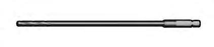
Joint Preparation Instruments Used: 1. Fenestration Drill, 2.5mm x 6" [27]

Using a lateral approach, reduce the joint to the correct position by rst exposing the subtalar joint. Distract the joint using a lamina spreader. Prepare the joint by completely removing cartilage from the posterior and middle facets using a sharp osteotome, a curette, and a rongeur until there is exposed bleeding subchondral bone. Leave the overall contours of the bones intact. Once all cartilage is removed, use a sharp osteotome to “ sh-scale” the posterior and middle facets. The 2.5 mm Fenestration Drill can be used to aid in creating bleeding bone and feathering the joint surface. Assure that the bleeding bone surfaces are in apposition before proceeding. Place any graft material if desired.

3
Place the Guidewire
Instruments Used: 1. Guidewire, 2.4 mm x 380 mm [19]
Make a 2 cm incision down to the bone at the posterior-plantar junction of the calcaneal tuberosity.
Compress the joint before placing the Guidewire and keep joint in proper orientation and under compression throughout procedure. Steinmann pins may be used to xate the subtalar joint if desired.
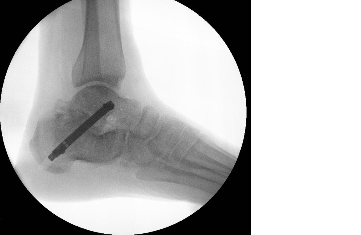
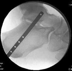
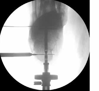
Guidewire Placement Tips On the lateral view, aim the Guidewire anterior to the bula and toward the anterior third of the talar body. Refer to the “Safe Zone” in the image to the left.
Advance the Guidewire until the Tip is about 2-3 mm short of the anterior cortex.

Ensure that the trajectory of the Guidewire does not cross the bula on lateral uoroscopy. On A-P uoroscopy, Guidewire should appear centered or slightly biased toward the medial side. If necessary, the foot may be plantar exed to create more space to drill for the talar screw.
Safe zone between dashed lines

4
Reaming Entry Canal
Instruments Used: 1. Soft Tissue Protector [20] 2. 7.5 mm Cannulated Drill (if using 7 mm Nail Implant) [11] 3. 8.5 mm Cannulated Drill (if using 8 mm Nail Implant) [14]

Place the Soft Tissue Protector over the Guidewire against the posterior aspect of the calcaneus. Select the cannulated drill that is 0.5 mm larger than the selected Implant diameter and insert over the Guidewire into the Soft Tissue Protector. Drill over the path of the Guidewire until the proximal tip of the drill is a few millimeters distal to the anterior cortex of the talus.
TECH TIP • If difficult to insert the Nail Implant, then drill 1 mm larger than the selected Implant diameter.
5
Determining Implant Length Instruments Used: 1. Trial Sizer, 60 mm - 100 mm [23]
Several methods are available to determine appropriate nail length.
Option 1: Lasermarks on the Cannulated Drill may be read off the back of the Soft Tissue Protector. Subtract 40 mm from the lasermark reading to determine the necessary Nail Implant length (A).
TECH TIP • Select a Nail Implant length that is at least 5 mm shorter than the tunnel depth to allow the Nail Implant to be inserted
Screw Hole:
sub-flush and to accommodate for Manual Compression.
Option 2 (Recommended): Remove the Cannulated Drill and insert the Trial Sizer into the reamed tunnel until the proximal screw hole is in the desired position in the talus, as viewed on lateral uoroscopy.
The proximal screw hole should be just anterior to the bula. Use the etched lines on the distal end of the Implant Trial to determine the appropriate position of the distal end of the
TECH TIP • If the Trial Sizer is inserted over the Guidewire, the screw holes will not be visible. In such cases, remove the Guidewire. If necessary, the Guidewire can be reinserted through the Trial Sizer after sizing is determined.
Transverse Talar
Implant in the calcaneus (B).
Verify that the fibula is not obstructed

Distal end of Nail Implant:
Verify at least 5 mm sub-flush to allow for manual compression
A
B
Implant Attachment Instruments Used: 1. Targeting Frame [5] 2. Bone Apposition Sleeve [6] 3. Compression Knob [7] 4. Retention Knob [8] 5. DynaNail Mini Implant
Attach the pre-stretched DynaNail Mini Implant Assembly onto the Targeting Frame and turn the Retention Knob clockwise to securely tighten. Thread the Bone Apposition Sleeve onto the Compression Knob by turning counter-clockwise until it stops (A). With the Bone Apposition Sleeve oriented up, advance the Manual Compression Knob over the DynaNail Mini Assembly and down past the ball bearing until it clicks into place.
TECH TIP • Before inserting the Nail Implant, check the drill targeting by inserting the Guide Sleeve, Drill Guide, and 4 mm Drill into the appropriate hole in the Targeting Frame and advance the Drill until it passes through the proximal screw hole in the Nail Implant.
A
DynaNail Mini Assembly

Bone Apposition Sleeve
Compression Knob
Targeting Frame
Retention Knob

7
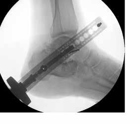
Implant Insertion Instruments Used: 1. Targeting Frame [5]
Insert the Nail Implant into the drilled canal such that the Arm of the Targeting Frame is on the lateral side of the foot. If necessary, mallet on the Retention Knob to help advance the Implant. Do NOT mallet on any other part of the Targeting Frame beside the Retention Knob.
Use uoroscopy to determine that proper depth has been reached.
TECH TIPS • Check Implant positioning on A-P and lateral fluoroscopy before proceeding to the next step.
Recommendations for Implant Placement: On lateral uoroscopy, ensure that the bula is not obstructing the proximal talar screw hole.

The distal end of the Nail Implant can be visualized as a translucent area in the Nail Guide on lateral uoroscopy.

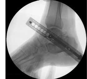
Transverse Talar Screw Hole:
Verify that the fibula is not obstructed
Distal end of Nail Implant:
Verify at least 5 mm sub-flush to allow for manual compression
8
Provisional Fixation of Targeting Frame Instruments Used: 1. Steinmann Pin, 2 mm x 9" (quantity 2) [17]
Provisional xation is recommended for stabilizing the frame and ensuring proper screw placement. To provisionally xate the Targeting Frame, drill two Steinmann Pins through the small holes anterior and posterior to the intended hole for drilling the Transverse Talar Screw hole.


9
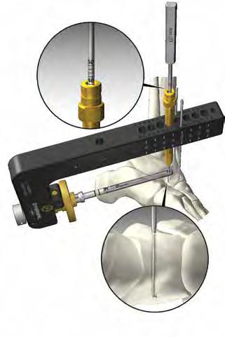
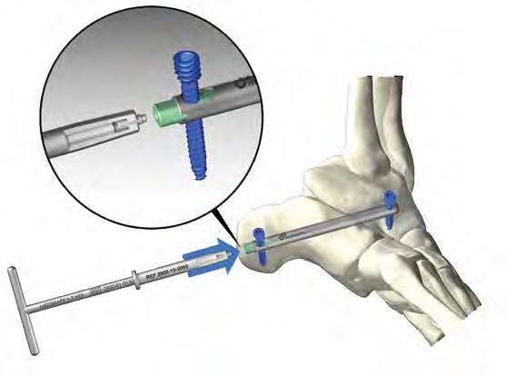
Drilling for Transverse Talar Screw Instruments Used: 1. 6.5 mm Guide Sleeve [9] 2. 4 mm Drill Guide [10] 3. 4 mm Transverse Screw Drill [15]
Insert the 6.5 mm Guide Sleeve into the appropriate hole on the Targeting Frame corresponding to the selected Nail Implant length. If necessary, make an incision where the Guide Sleeve contacts the skin. Insert the 4 mm Drill Guide into the Guide Sleeve. Do NOT rest the Drill Guide on the bone as this may alter the drilling trajectory.
TECH TIPS • Ensure the incision does not push on the drill guide before drilling
Using the 4 mm Transverse Stepped Drill, drill to the medial cortex through the proximal screw hole in the Nail Implant. Use uoroscopy to ensure full drill depth has been reached. Advance the Drill Guide against the bone prior to the next step.

TECH TIPS • Do NOT advance the Drill tip beyond the medial cortex such that the Drill extends past the taper. The end of the Headless
Screw is tapered and will lose purchase on far cortex if over drilled.

10

Measuring Screw Length Instruments Used: 1. Screw Depth Gauge [18]
There are two methods for determining screw length:
Option 1 With the Drill Guide abutted to the bone, read the lasermarks on the Drill off the back of the Drill Guide.

Option 2 The Screw Depth Gauge may be inserted through the Drill Guide. With the Drill Guide against the bone, read the lasermarks on the Depth Gauge off the back of the Drill Guide.
Transverse Talar Screw Insertion Instruments Used: 1. 3 mm Hex Driver [2] 2. Blue-Handle Ratchet Driver [4] 3. Headless Screw
Attach the 3 mm Hex Driver to the Blue-Handle Ratchet Driver. Remove the 4 mm Drill and Drill Guide from the Guide Sleeve. Place the Transverse Headless Screw onto the 3 mm Hex Driver and insert into the Guide Sleeve. The Transverse Headless Screw does not provide any tactile feedback to indicate when it is fully inserted. When the lasermarking on the 3 mm Hex Driver approaches the back of the Guide Sleeve, use lateral uoroscopy while advancing the nal turns, ensuring the Screw tip does not extend beyond the medial cortex of the talus. Remove the Hex Driver and Guide Sleeve from the Targeting Frame.
TECH TIP • Do NOT use power for Headless Screw insertion. • Check on A-P fluoroscopy to verify screw depth.
12
Apply Manual Compression Ensure the plantar incision is big enough for the Bone Apposition Sleeve to butt against the bone before applying manual compression. To apply manual compression, turn the Compression Knob in a clockwise direction as indicated by the arrows on the Knob.
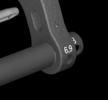
The approximate amount of manual compression applied can be determined by reading the lasermarkings on the Bone Apposition Sleeve of the Targeting Frame and taking the difference before and after applying manual compression.
IMPORTANT NOTE: The Compression Knob will disengage from the Targeting Frame once the distal end of the Nail Implant has reached the posterior cortex of the calcaneus to prevent it from being positioned outside the bone.


Laser markings
13
Calcaneal Screw Drilling & Insertion Instruments Used: 1. 6.5 mm Guide Sleeve [9] 2. 4 mm Drill Guide [10] 3. 4 mm Transverse Screw Drill [15] 4. 3 mm Hex Driver [2] 5. Blue-Handle Ratchet Driver [4] 6. Headless Screw
Insert the 6.5 mm Guide Sleeve and 4 mm Drill Guide into the distal hole on the Targeting Frame. Make an incision parallel to the sural nerve down to the calcaneus. Follow the same technique outlined in Steps 8 – 10 to drill a pilot hole and determine proper screw length.
Insert a 4 mm Headless Screw using the 3 mm Hex Driver ensuring the Screw has reached but does not extend past the medial cortex in the calcaneus. Remove the Guide Sleeve.
14
Release Nail Instruments Used: 1. 2 mm Hex Driver [3] 2. Blue-Handle Ratchet Driver [4]
Attach the 2 mm Hex Driver to the Blue-Handle Ratchet Driver. To release the Nail Implant from the Targeting Frame, insert the 2 mm Hex Driver into the back of the Retention Knob. Unscrew the Connection Screw by turning counterclockwise (A).
This will release the Sliding Element from the Nail Guide and activate the NiTiNOL Compressive Element.
Connection Screw
A
Releasing from Frame


Screw insertion

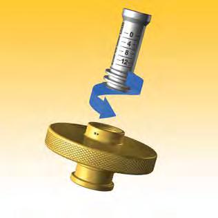
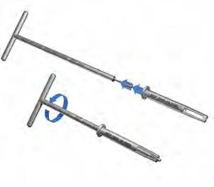
Insert End Cap Instruments Used: 1. 1.3 mm T-Handle Driver [1] 2. End Cap Holder [26] 3. End Cap
Place the End Cap onto the end of the 1.3 mm T-Handle Driver (A). Slide the End Cap Holder over the Entire Assembly until the End Cap Holder butts against the End Cap. Turn the T-Handle clockwise until several threads of the End-Cap extend past the tip of the End-Cap Holder (B). Thread the End Cap into the distal end of the Sliding Element in the Nail Implant until nger tight. Check nal positioning of Nail Implant using uoroscopy (C).
Close incisions per surgeon preference.
Assembling End Cap Holder
A
B
Final insertion of End Cap