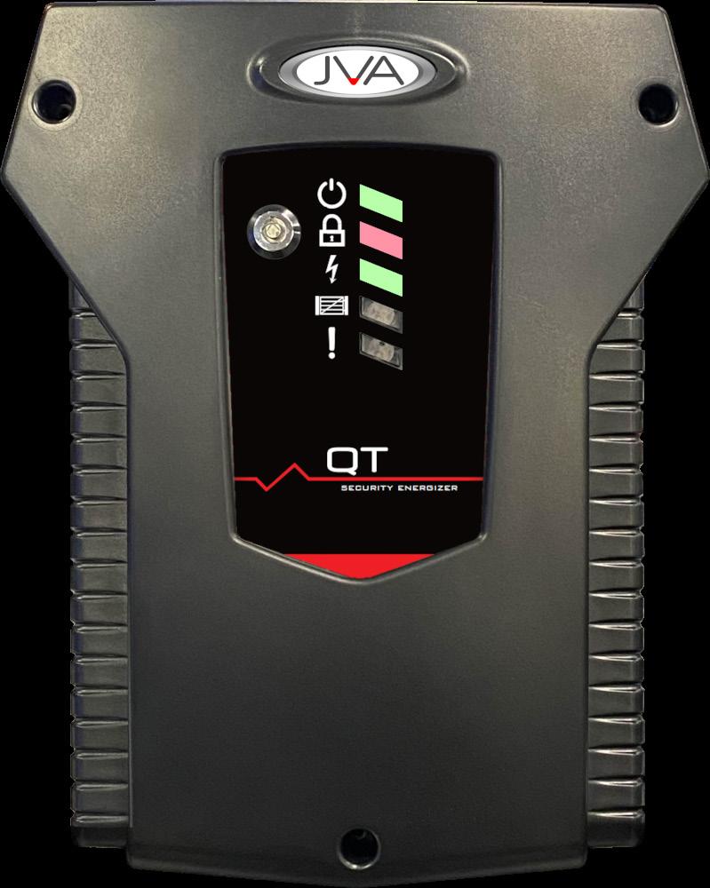

The QT Energizer is JVA’s smallest standalone security electric fence energizer.
• Meets Safety and EMC standards (reports available on request)
• 1J or 3J Output power (Model dependent)
• High power and Low power mode
• Built-in charger and space for a 12V 2.2Ah Lead Acid or 4Ah JVA LiFePO4 backup battery
• Alarms on fence short or open circuit
• AC fail, low battery and bad battery detection
• Simple LED display
• Onboard configuration switches for simple programming
• One 12V dc switch Output and two relay Outputs
• Two control Inputs configured as N.O. or N.C. contacts
• Optional Virtual Keypad Module (VKP) for advanced programming and features
• Optional 433MHz interface for Remote control or Wireless sensors
For the most up-to-date and full version of this user manual, please visit: www.jva-fence.com/qt
Indicator
The QT is powered from mains or battery
Red when the QT is operating in High Power mode
Flashing when operating in Low Power mode
Green flash indicates fence voltage is above the alarm threshold
Red flash indicates the fence voltage is below the alarm threshold
Red on indicates a fence alarm
Red flash indicates the Gate Input is open
Red on indicates the Gate Input is in alarm
Red flash(es) indicates an Error code
Low Voltage Input/Output
Terminals
Glass Fuse
Shunts to connect 12V to relay common
Key Switch Connector
433MHz Antenna connection
Alarm Settings Switch
Pairing Switch
Fence Terminals
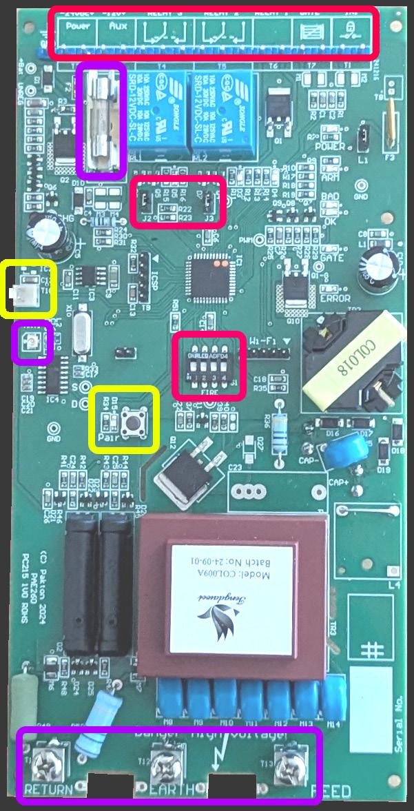
The QT contains 2 Inputs and 3 Outputs that can be used to interface to an alarm panel or other site hardware. The Input and Output functions can be altered through the optional Virtual Keypad (VKP).
The two Inputs should be connected to dry contact switches/connections as these provide a 5V, 5mA sense current.
The Siren Output provides a 2-pin powered connection, the other two Outputs are relays with change over contacts. Each Output relay has a jumper that can connect the common terminal to 12V.
The 24Vdc supply Input is protected by a slow blow 1A glass fuse.
The common terminal of each relay can be connected to the +12V supply (battery) through the jumpers J2 and J3. Remove the black jumper/shunt to make the relay a dry contact. If the battery is not fitted, the +12V supply is the battery charger. This limits the total output supply to 350mA.
The cover key switch connects to the QT circuit board at this point. This allows the switch to be easily disconnected during servicing.
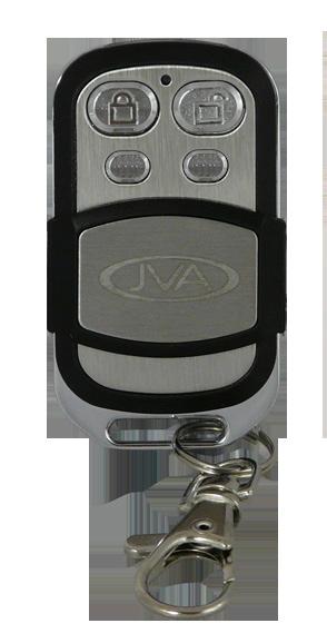
This receiver provides the ability to Arm or Disarm the energizer via a compact keychain fob remote control. The JVA remote control has individual Arm/Disarm buttons, as well as buttons for low power and panic.
The receiver can also be used to pair approved 433MHz sensors such as door contacts, PIRs, or Roboguard beams. This function is only available if the optional VKP is installed.
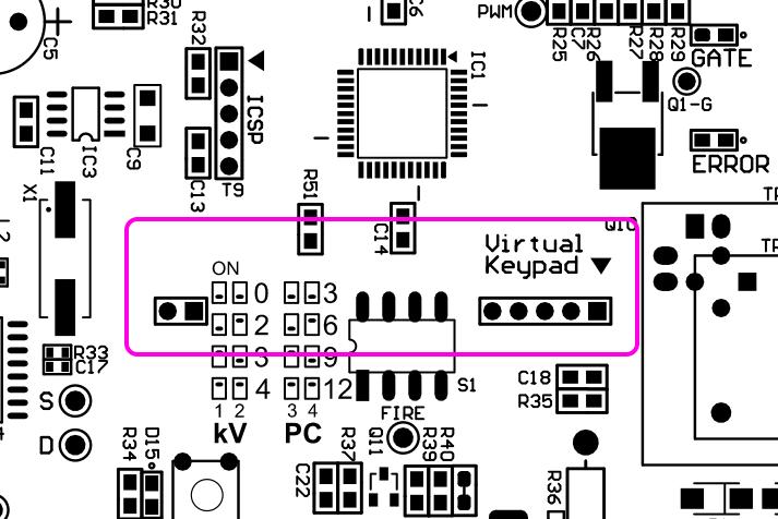
The 4 switches on the board are used for setting the fence voltage threshold and the alarm delay time. There are 4 values for each of the voltage and delay settings.
The push button is used in the pairing process for the 433MHz remotes. This button is also used to default the board, or VKP settings.
High voltage cabling (fence feed and return) should be run using suitably rated cable. Double insulated electric fence “underground” cable is suitable. High voltage cables must never be run within the same conduit as low voltage cables. A minimum distance of 50mm should be kept between high voltage and low voltages cables.
Low voltage cables must be installed in the enclosure channel to the right of the battery to ensure a good isolation from the high voltage components and terminals.
The Virtual Keypad Module provides a browser-based user interface accessible over the 2.4GHz frequency band via smartphone, tablet, or computer.
This module allows for improved configuration of the QT Energizer. It also provides a gateway between the QT and either of the JVA Cloud services:
• IP Energizer Controller
• Cloud Router.
To access these services, a continuous internet connection is required. Each user will also have to install the relevant App (Android/iOS) on their phone. Once connected, offsite control and monitoring of the QT can be achieved as long as the phone has internet access.
When the Virtual Keypad module is installed onto the QT, it will disable the switch settings on the main board. These settings are now configured via the user interface.
JVA recommends installation by qualified technicians.
1. Read the entire manual first!
2. Design and build the fence (beyond the scope of this manual). Ask your distributor for help if required.
3. Decide where to mount the QT. If on an external wall, it should be housed within a waterproof equipment box and not in direct sunlight.
4. Secure 2 screws to the mounting point at 100mm separation. A template is provided on the box. Ensure the screw heads stand 5mm proud of the mounting surface.
5. Remove the 3 QT enclosure screws and place the cover down, taking care of the light pipes. The PCB should not need to be removed.
6. Fit the mains cable into the back of the QT enclosure base, directly into the power supply.
7. Secure the mains cable with a cable tie.
8. Mount the QT enclosure base onto the wall screws. Tighten the screws down
9. Wire the low voltage cables to the pluggable blue terminals*.
10. Wire the high voltage cable to the fence terminals*.
11. Connect the Mains plug to the socket and turn it on, confirm the unit powers up.
12. Turn the Mains off and confirm the unit powers off.
13. Fit the battery to the PCB. Confirm the unit powers up.
14. Replace the front cover, fitting the key switch cable onto the pins.
15. Turn on the Mains.
16. Use the key switch to confirm the QT starts firing.
* NOTE: Keep high voltage and low voltage cables at least 50mm apart. Do not run high and low voltage cables in the same conduit.
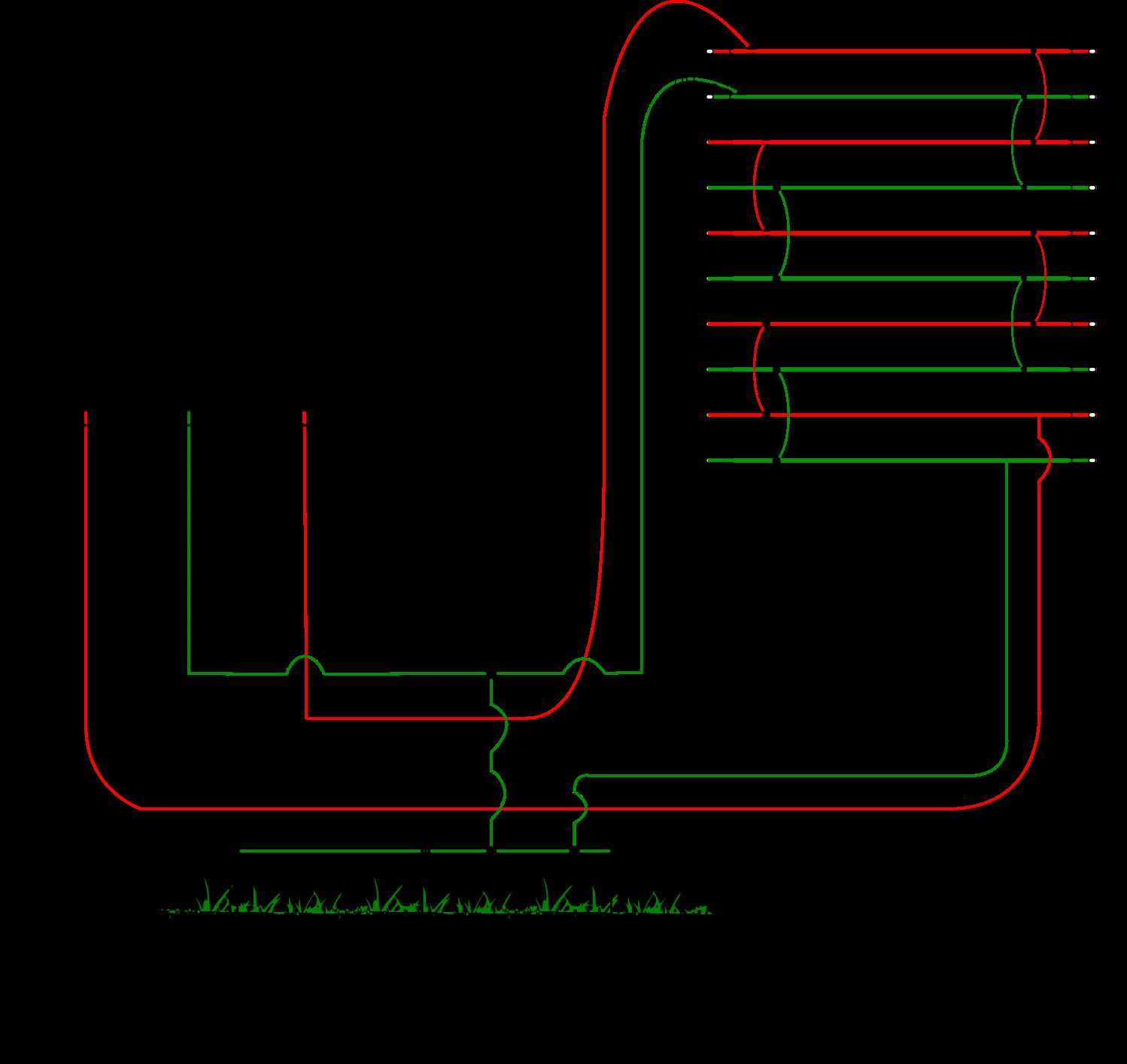
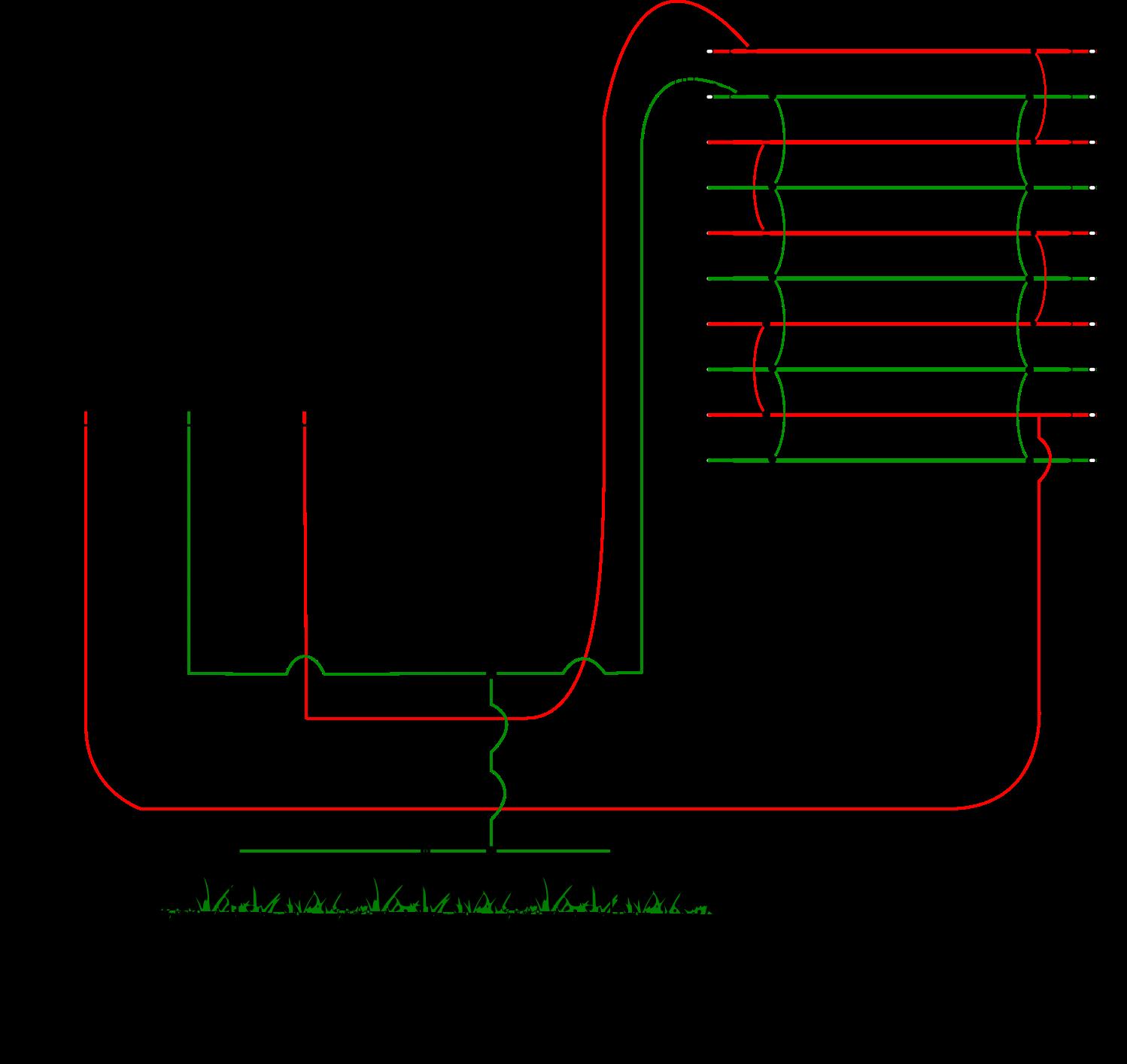
The QT security energizer may be Armed/Disarmed using any of the following:
• Key switch
• Control Input (IN1)
• Remote control (requires optional 433MHz receiver)
• Virtual Keypad (requires optional Virtual Keypad Module)
• Mobile App (requires optional Virtual Keypad Module)
More than one method may be used in the one installation.
The 4-position slide switch controls the alarm settings when the VKP module is not fitted.
SW1 SW2 Alarm Threshold Low Power Threshold
OFF OFF 0kV (Alarm Disabled) Alarm Disabled OFF ON 2kV 30V ON OFF 3kV 50V ON ON 4kV 100V
SW3 SW4 Alarm Delay (Pulse Count) OFF OFF 3 pulses OFF ON 6 pulses ON OFF 9 pulses ON ON 12 pulses
A return voltage below the Alarm Threshold for consecutive Alarm Delay pulses will trigger the fence alarm.
If the QT is armed and the fence is tampered with, the red fence light will flash and then remain on. A siren and/or strobe connected to the unit will turn on.
An alarm will also occur if the gate Input is opened and the entry/exit delay time has elapsed.
The Siren will be silenced if the QT is Disarmed.
There is also a MUTE button in the VKP to allow the Siren to be silenced without Disarming.
The Strobe Output (Output 2) will remain on after the QT is Disarmed, it will turn off when the QT is re-armed.
There is also a CLEAR button in the VKP to turn off the Strobe Output without Disarming the QT. The Cloud Router App can also clear the Strobe Output. The Output will turn back on immediately if the fence voltage is still below the alarm setting.
The 433MHz interface provides the QT with wireless control using the JVA Remote Control. The QT can pair with up to 12 remotes providing Arm, Disarm, Arm Low, and Panic functionality through individual button control.
To pair a remote, press the Pair button. The Pair LED will start to flash to indicate it is ready to pair. On the remote, press the Disarm button once, wait 1 second and press it again. The Pair LED will change from flashing to ON for 2 seconds to show that the remote has been paired. Pressing the button again will be indicated on the Pair LED as a short flash.
The 433MHz antenna may require fitting to the ANT1 connection after installing the antenna. The connector needs to be aligned with the ANT1 header and then firmly pressed onto it. The fitting is a ‘press fit / snap’ which allows this to be disconnected again if necessary.
If the optional Virtual Keypad module is added to the QT board, the 433MHz interface can be used to monitor up to 8 sensors. NOTE: The maximum number of 433MHz devices that can be paired is 12.
Pairing of sensors can only be achieved through the VKP interface.
To remove all paired devices without a VKP module, power off the QT Energizer by unplugging both the battery and Mains connections. Power the device on again and, within the first 10 seconds, press and hold the Pair button for 3 seconds.
The LEDs will start to cycle in sequence, indicating the Default process has started. This will clear all RF Devices and any other pre-programmed settings.
NOTE: this method only works with energizers that do not have the VKP module fitted. If your energizer has a VKP module, see section 6.6 on page 20.
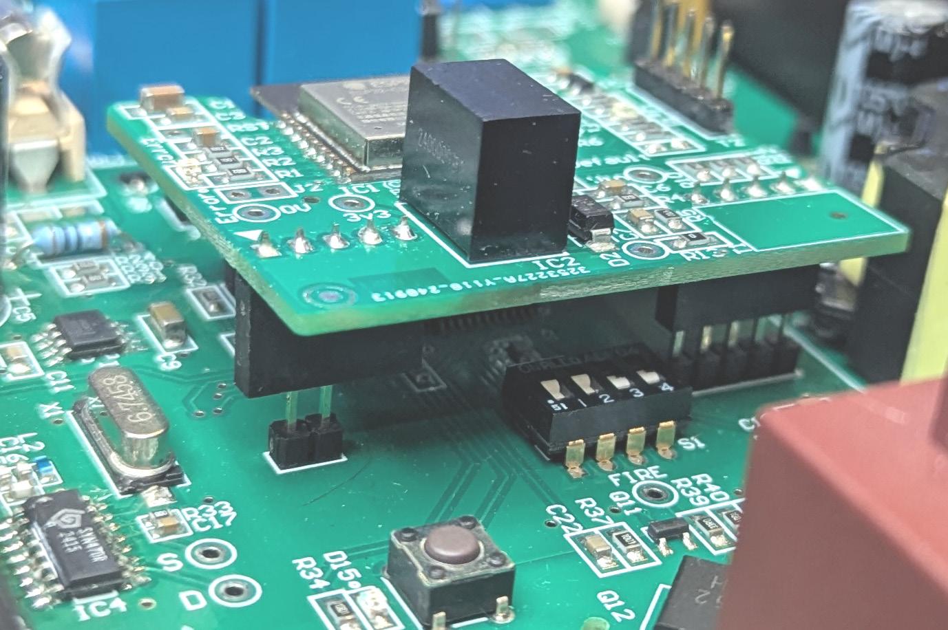
Ensure the QT is not powered and then align the Virtual Keypad PINs on the QT Energizer with the VKP module socket. There are 2+5 pins that are marked as “Virtual Keypad”. Press the module down until it is fully seated.
SSID Password: jvasecure
Browser Address: 192.168.4.1
The JVA Virtual Keypad (VKP) is a browser based user interface used to view and manage the QT. To connect to the VKP ensure the QT is powered and you are within 25m of the unit. On a smartphone/tablet open the WiFi settings and connect to the SSID containing the serial number of the QT. Enter the SSID Password and press the connect button.
The phone browser should automatically open to the QT Main page. If it does not, manually open a browser and access the VKP by entering the address 192.168.4.1 into the browser.
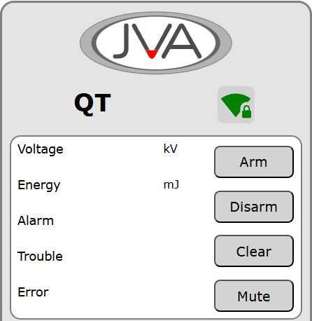
The main screen contains the control buttons for the Energizer. It also displays the fence readings and any alarm messages. The information on the page refreshes every 2-3 seconds.
The lower section contains the QT details including mains supply and battery voltage readings.
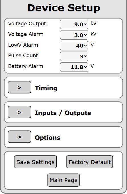
The device setup page contains 4 sections for configuring the QT Energizer.
To expand the sub pages, press the > button. To hide again, press the ^ button.
After changing the settings, press the Save Settings button to send the new values to the QT.
Pressing the Factory Default button will send the Default command to the QT. The Reload Settings button will flash to update the page with the updated values.
This section is for configuring the Siren Output On/Off/Cycle times (explained further in ‘Output Functions’ on page 16) and Delays, explained below:
Gate Delay - A Gate Input will trigger an alarm if the Input remains ‘open’ for longer than the Gate Delay.
Entry Delay - An Entry or Entry/Exit Input will trigger an alarm if the Input triggers and the QT is not Disarmed before the Entry Delay elapses.
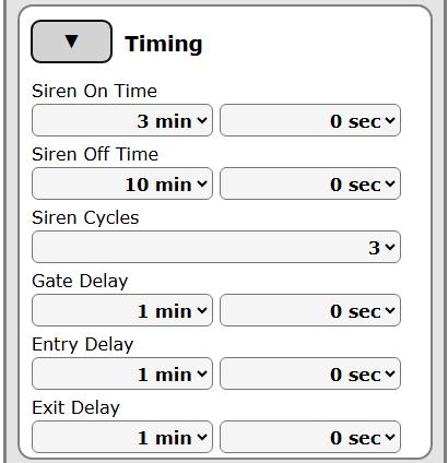
Exit Delay - An Exit or Entry/Exit Input is “bypassed” for the Exit Delay after the QT is armed. This allows someone to Arm and then exit the site through a dedicated path.
Each of the two Inputs and three Outputs can be configured for many functions.
Outputs normally follow the Output function until the fault/alarm clears. Setting a Latch Time can ensure the fault/alarm reports for a shorter time. If the fault/alarm clears earlier than the Latch time, the relay will also clear.
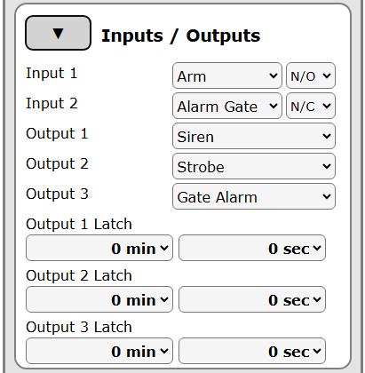
Input 1 default: Normally Open - Arm
Input 2 default: Normally Closed - Gate
Input Function Description
Arm This Input will Arm/Disarm the energizer.
Low Power This Input will switch the Armed energizer between High Power to Low Power.
Alarm Instant An Input Alarm will trigger on Input activation.
Alarm 3sec An Input Alarm will trigger after 3 seconds of continuous Input activation.
Alarm Gate The Gate Alarm trigger if the Input remains activate for the Gate Time value.
Entry/Exit Route
Combined Entry and Exit route system.
Entry Route When activated, the Entry Time starts to count down. The Alarm will trigger if the timer reaches zero and the GPIO is not Disarmed. This allows someone to enter the site through a dedicated path and access a keypad to Disarm without triggering the alarm.
Exit Route Inputs configured as Exit are “bypassed” for the Exit Delay after the GPIO is armed. This allows someone to Arm and then exit the site through a dedicated path.
Pass Thru The value of the Input is passed to a JVA App.
Input Function Description
Tamper A Tamper Alarm will trigger on Input activation.
Tamper Shutdown A Tamper Alarm will trigger on Input activation and the QT will be Disarmed.
24hr 24hr Alarm. This Alarm is not latched. It will follow the Input state, allowing an Alarm that does not require clearing through an App or the Virtual Keypad.
Input Hardware Description
N/O Normally Open Input, the function will trigger when the Input closes/shorts.
N/C Normally Closed Input, the function will trigger when the Input opens.
Tag Momentary Input, the Input function will toggle when the Input activates briefly.
Output 1 default function: Siren
Output 2 default function: Strobe
Output 3 default function: Gate Alarm
Output Function Description
Alarm The Output will trigger on a Fence Alarm.
Alarm or disarmed The Output will trigger on a Fence Alarm, or if the QT is Disarmed.
Armed The Output will trigger when the QT is Armed.
General This Output triggers on Supply Fail / Gate Alarm / Low Battery / Tamper.
Siren When an Alarm occurs, the Siren Output will turn on for the Siren On time, it will then turn off for the Siren Off time. This will repeat for the Siren Cycles.
Strobe The Output will trigger on an Alarm and it will remain latched if the QT is Disarmed. The Output will clear on the next Arm, or if the Clear button in the VKP is pressed.
Output Function Description
Supply Fail
Low Battery
Tamper
Gate Alarm
Input 1 Alarm
Input 2 Alarm
6.4.3
The Output will trigger if the Mains supply fails.
The Output will trigger if the battery voltage drops below the threshold.
The Output will trigger when the QT is in Tamper.
The Output will trigger with a Gate Alarm.
The Output will trigger if Input 1 Alarms.
The Output will trigger if Input 2 Alarms.
Option Description
VKP Low Power Button
Bypass Battery Fail
Bypass Supply Fail
Siren: Arm Chirp
Siren: Gate Chirp
When enabled, the Main Page of the VKP will display the Arm Low Power button for use.
The unit will continue to operate without detecting / reporting any battery faults.
The unit will continue to operate without detecting / reporting a fault with the 24V supply.
The Siren Output will turn on for 0.2 seconds to indicate it has been Armed.
The Siren Output will turn on for 0.2 seconds twice to indicate it has been Disarmed.
The Siren Output will turn on for 1 second to indicate the Gate Input has been opened.
The Siren Output will turn on for 1 second twice to indicate the Gate Input has been closed.
Default Option enabled: Siren Arm Chirp.
This page is accessed from the main screen of the QT VKP.
The options for App selection are:
• IPEC App - Simplified interface initially designed for Agric Energizers
• Cloud Router - Detailed Security App with logging and PC browser support
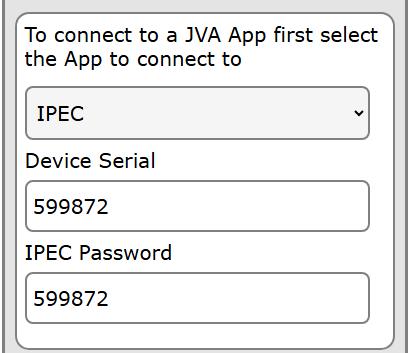
• Disabled - For direct VKP connection using a PC or Tablet - no App download required
The Device Serial will be used in both the IPEC and Cloud Router App to add the QT to the system.
The IPEC Password is user configurable and is required when adding the QT to the IPEC App system.
The next step is to press the SCAN button to detect available Access Points in the area. Select the best option and then enter the Password.
Finally, press the CONNECT button. The VKP module must restart to connect to the App systems. This means the phone/tablet will need to reconnect to the VKP to access the user interface again.
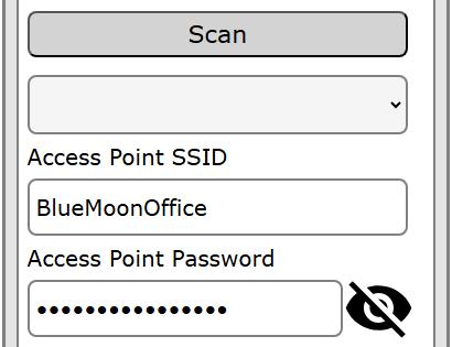
The LEDs on the VKP board will flash to indicate the progress of the App connection.
• 2 fast flash - attempting connection
• 3 fast flash - connection established
• Slow flash - connection to the App server established
The RF Devices page is accessed from the main screen of the VKP. The page shows the paired devices in the order that they were paired. Each device can be named to provide a useful reference.
To pair a device, press the type of device to be paired. The Pair LED on the QT will begin to flash. Trigger the device:
• Press the Disarm button on a remote
• Trigger the Alarm on a PIR
• Trigger an Alarm on a Door Contact
• Trigger the Tamper switch on a Roboguard
After Pairing, press the Stop button
The device should appear in the list. Enter a name for the device and then press the Save Names button.
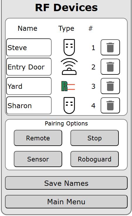
To unpair a device, press the bin icon to the right of the device.
The VKP can be updated to the latest version through the Firmware Update page. This will only update the VKP, not the main board of the QT Energizer.
To perform an update, the VKP needs to be connected to the network through the Cloud App Settings page first.
The Firmware Update system will connect to the JVA Servers to find the available versions. Choose the version to be installed (the newest version available will be selected automatically). Press the button to Install this version.
The installation will take up to 10 minutes to complete. The two LEDs on the VKP module will flash alternately to show it is progressing.
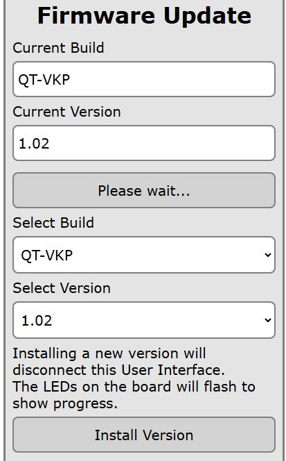
The VKP will stop responding to user actions during this process and it will restart once complete. The Error LED on the VKP will show if there was an issue with the download by blinking a pattern.
The VKP Settings can be altered to improve the security of the VKP system.
VKP Name This will be the name of the VKP to connect to with a phone, tablet or computer.
VKP Password This is the connection password required to access the VKP. It is recommended that this is changed from the default value.
IP Address
When connecting to the VKP, this is the default IP address to enter into a Browser to access the interface.
If the connection details for the VKP are forgotten, the factory default values can be returned. power off the QT Energizer by unplugging both the battery and Mains connections. Power the device on again and, within the first 10 seconds, press and hold the Pair button for 3 seconds.
The LEDs will start to cycle in sequence, indicating the Default process has started. The VKP LEDs will then start to flash showing the factory default was successful.
Spec Condition Value Supply Voltage
Minimum (required to charge the battery) 28Vdc 16Vdc Battery Voltage Flat Battery
Battery
QT11 current (from 12.5V battery)
QT13 current (from 12.5V battery)
Charging Average (Light Load)
Charging Peak (Light Load)
Charging Average (Heavy Load)
Charging Peak (Heavy Load)
QT13 Peak Fence Energy @500R
QT13 Peak Stored Energy @500R
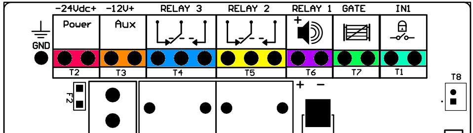
Label Pins
Description
1 Connect to a reliable mains earth/ground before the product is operated.
24Vdc 2 24Vdc power Input.
12V 2 12V auxiliary Output. Fused at 0.5A.
Relay 3 3 Relay contacts. Default function is Gate Alarm.
Relay 2 3 Relay contacts. Default function is Strobe.
Relay 1 2 Switched 12V Output. Default function is Siren. The left pin is +ve
Gate 2 Input 2. Default function is normally closed Gate Alarm.
IN1 2 Input 1. Default function is normally open Arm/ Disarm.
The QT has two sources of power: 24Vdc (integrated power supply) and 12V (battery). The internal standby battery provides sufficient power to maintain the operation of the QT if mains power is lost for a short time. If the mains interruption is prolonged, the battery may discharge fully and become damaged.
The QT battery chemistry can be either a sealed lead-acid/gel or a lithium battery. Ensure the Li shunt is fitted for a lithium battery.
The QT will flash the status LED to indicate an error.
The QT uses the following system to display error codes:
• A slow, 0.5 second flash represents a count of 1
• A fast, 0.2 second flash represents a count of 5
• Counts are to be summed together to display the error code
For example, two fast flashes followed by two slow flashes would be error 12 (5 + 5 + 1 + 1) - Battery Over-Temperature.
Main capacitor charged, but not Fired.
24Vdc Input voltage is too high.
Writing to internal memory failed.
Connecting leads - electric conductor used to connect the energizer to the electric fence or the earth electrode.
Physical barrier - a barrier not less than 1.5m high intended to prevent inadvertent contact with the pulsed conductors of the electric fence.
Secure area - an area where a person is not separated from pulsed conductors below 1.5m by a physical barrier.
Public access area - any area where persons are protected from inadvertent contact with pulsed conductors by a physical barrier.
Pulsed conductors - conductors that are subjected to high voltage pulses by the energizer.
Electric security fences and their ancillary equipment shall be installed, operated and maintained in a manner that minimizes danger to persons, and reduces the risk of persons receiving an electric shock unless they attempt to penetrate the physical barrier, or are in the secure area without authority.
Electric security fence constructions that are likely to lead to the entanglement of persons shall be avoided.
Gates in electric security fences shall be capable of being opened without the person receiving an electric shock.
An electric security fence shall not be supplied from two separate energizers or from independent fence circuits of the same energizer.
For any two separate electric security fences, each supplied from a separate energizer, the distance between the wires of the two separate electric security fences shall be at least 2.5m. If this gap is to be closed, this shall be effected by means of a physical barrier of high voltage insulating material or earthed conducting material such that the two separate security fences cannot be contacted at the same time.
A spacing of 2.5m shall be maintained between uninsulated connecting
leads supplied from separate energizers. This spacing may be less where
• the connecting leads are covered by insulating sleeving rated to at least 10 kV at mains frequency; or
• the connecting leads consist of insulated cables rated to at least 10 kV at mains frequency; or
Barbed wire or razor wire shall not be electrified by an energizer.
For earthing recommendations, follow the relevant national standard for electric security fence earthing. If this does not exist then follow the energizer manufacturer’s instructions and recommendations.
The distance between any electric security fence earth electrode and other earth systems shall be not less than 2 m, except when associated with a graded earth mat.
Where possible, the distance between any electric security fence earth electrode and other earth systems should preferably be at least 10 m.
Exposed conductive parts of the physical barrier shall be effectively earthed.
Where an electric security fence passes below bare power line conductors, the highest metallic element shall be effectively earthed for a distance of not less than 5 m on either side of the crossing point.
Connecting leads that are run inside buildings shall be effectively insulated from the earthed structural parts of the building. This may be achieved by using insulated high voltage cable.
Connecting leads that are run underground shall be run in conduit of insulating material or else insulated high voltage cable shall be used. Care shall be taken to avoid damage to the connecting leads due to the effects of vehicle wheels sinking into the ground.
Connecting leads shall not be installed in the same conduit as the mains supply wiring, communication cables or data cables.
Connecting leads and electric security fence wires shall not cross above overhead power or communication lines.
Crossings with overhead power lines shall be avoided wherever possible. If such a crossing cannot be avoided, it shall be made underneath the power line and as nearly as possible at right angles to it.
If connecting leads and electric security fence wires are installed near an
overhead power line, the clearances shall be not less than those shown in table.
If connecting leads and electric fence wires are installed near an overhead power line, their height above the ground shall not exceed 3 m.
This height applies either side of the orthogonal projection of the outermost conductors of the power line on the ground surface, for a distance of
• 2m for power lines operating at a nominal voltage not exceeding 1,000 V.
• 15m for power lines operating at a nominal voltage exceeding 1,000V.
Electric security fences shall be identified by prominently placed warning signs.
The warning signs shall be legible from the secure area and the public access area.
Each side of the electric security fence shall have at least one warning sign.
Warning signs shall be placed
• at each gate;
• at each access point;
• at intervals not exceeding 10 m;
• adjacent to each sign relating to chemical hazards for the information of the emergency services.
Any part of an electric security fence that is installed along a public road or pathway shall be identified at frequent intervals by warning signs securely fastened to the fence posts or firmly clamped to the fence wires.
The size of the warning sign shall be at least 100 mm × 200 mm.
The background colour of both sides of the warning sign shall be yellow. The inscription on the sign shall be black and shall be either
• the symbol shown below, or
• the substance of “CAUTION: Electric fence”.
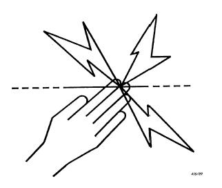
Ensure that all mains operated, ancillary equipment connected to the electric security fence circuit provides a degree of isolation between the fence circuit and the supply mains equivalent to that provided by the energizer.
Mains supply wiring shall not be installed in the same conduit as signalling leads associated with the electric security fence installation.
Protection from the weather shall be provided for the ancillary equipment unless this equipment is certified by the manufacturer as being suitable for use outdoors, and is of a type with a minimum degree of protection IPX4.
8.3.1 General
An electric security fence should be installed so that, under normal conditions of operation, persons are protected against inadvertent contact with pulsed conductors.
This requirement is primarily intended to establish that a desirable level of safety is present or is being maintained in the physical barrier.
When selecting the type of physical barrier, the likely presence of young children should be a factor in considering the size of openings and a risk assessment shall be made prior to installation.
The electric fence should be separated from the public access area by means of a physical barrier.
Where an electric fence is installed in an elevated position, such as on the inner side of a window or skylight, the physical barrier may be less than 1.5m high where it covers the whole of the electric fence. If the bottom of the window or skylight is within a distance of 1.5m from the floor or access level then the physical barrier need only extend up to a height of 1.5m above the floor or access level.
Pulsed conductors shall not be installed within the shaded zone shown in Figure 8.
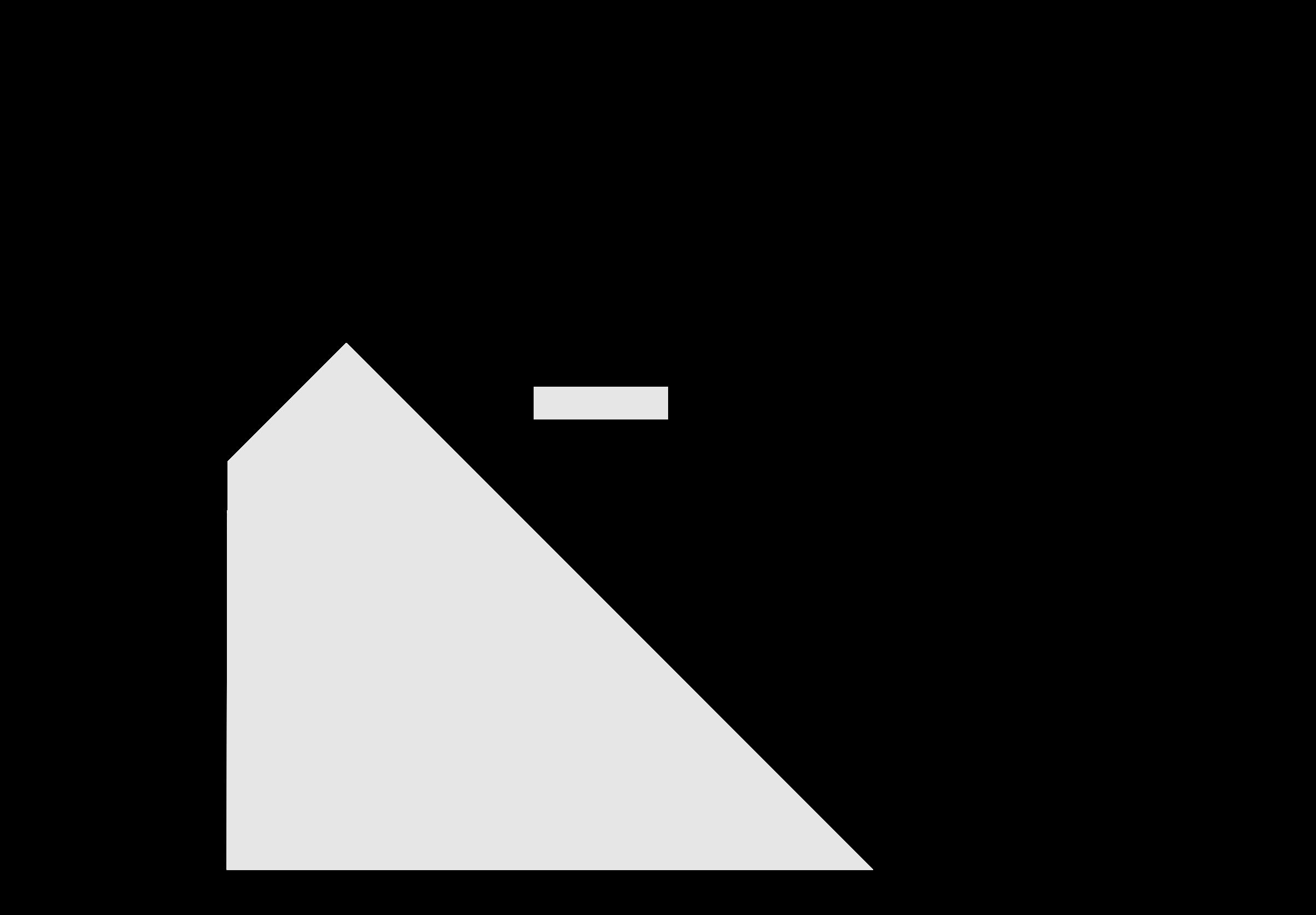
Where an electric security fence is planned to run close to a site boundary, the relevant government authority should be consulted before installation begins.
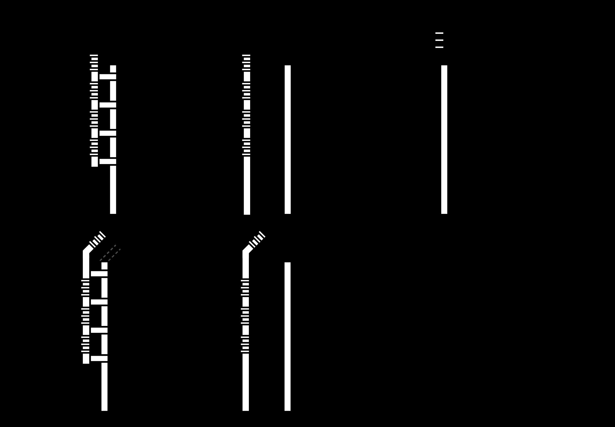
Typical Constructions where an Electric Security Fence is Exposed to the Public
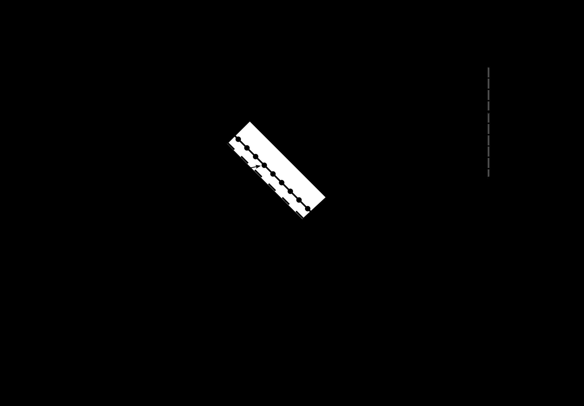
Typical fence constructions where the electric security fence is installed in windows and skylights
Where a physical barrier is installed in compliance with section 8.3.3, at least one dimension in any opening should be not greater than 130 mm and the separation between the electric fence and the physical barrier should be:
• within the range of 100 mm to 200 mm or greater than 1 000 mm where at least one dimension in each opening in the physical barrier is not greater than 130 mm;
• less than 200 mm or greater than 1 000 mm where the physical barrier does not have any openings.
NOTE:
1. These restrictions are intended to reduce the possibility of persons making inadvertent contact with the pulsed conductors and to prevent them from becoming wedged between the electric fence and the physical barrier, thereby being exposed to multiple shocks from the energizer.
2. The separation is the perpendicular distance between the electric fence and the physical barrier.
8.3.5
Electric fence conductors should not be mounted on a support used for any overhead power line.
8.3.6
The conductors of an electric fence should not be energized unless all authorized persons, within or entering the secure area, have been informed of its location.
Where there is a risk of persons being injured by a secondary cause, appropriate additional safety precautions should be taken.
NOTE: An example of a secondary cause is where a person may be expected to fall from a surface if contact is made with pulsed conductors.