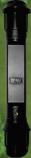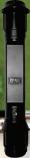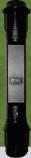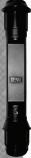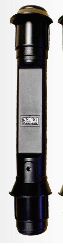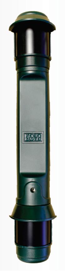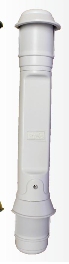


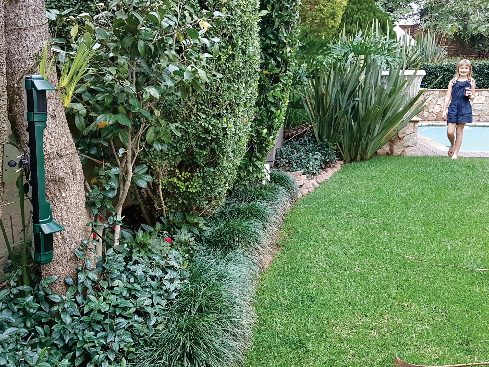

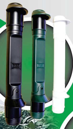


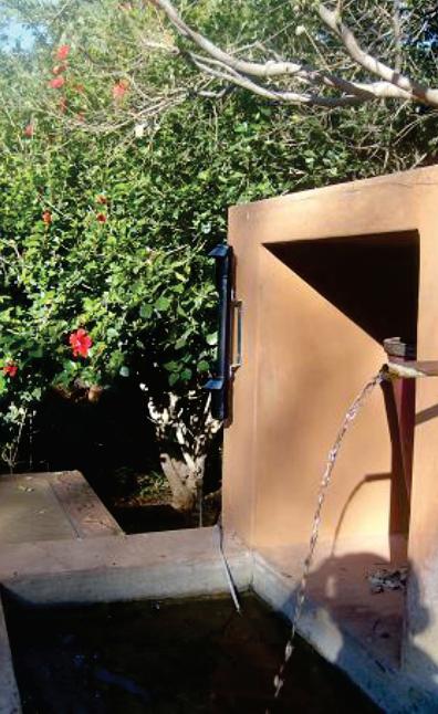
RoboguardBeam
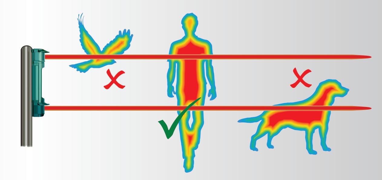
This is a battery operated, dual sensor, outdoor movement detector designed to detect intrudersandwirelesslytransmittheinformationtoaRoboguardBaseStation.
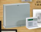
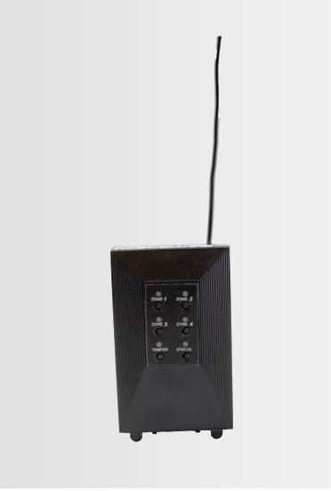
Portable Headquarters (HQ)
A portable 8-zone, 4-output, base station is used to receive and announce signals from up to 8 Roboguard Sensors. The HQ can also be wired to a siren and/or a hard-wired alarm panel.

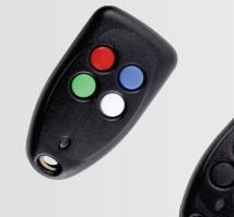
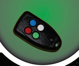
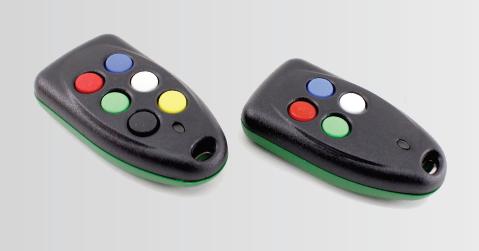
Keyfob Transmitter
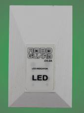
LED
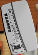
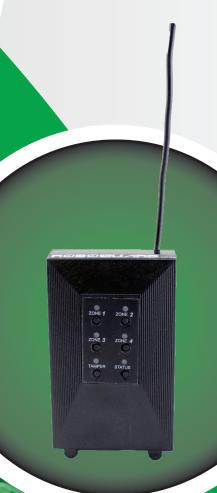
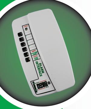
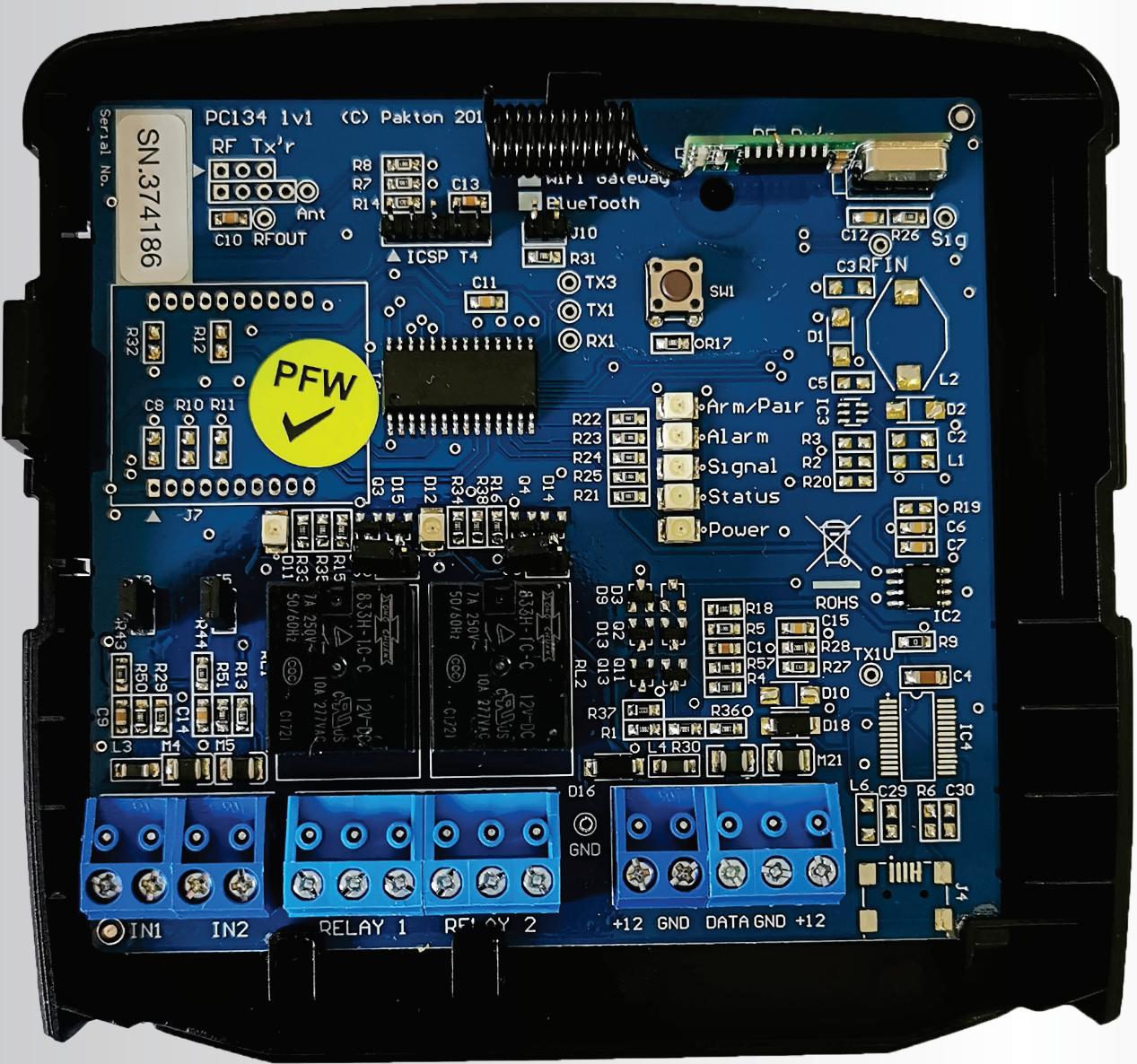
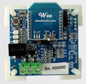
Alarm Interface
The Roboguard alarm interface is used to interface up to 4 Roboguards with individual intruder detect, tamper and status LEDs.
Power pack
The HQ interfaces with external devices such as a siren and/or alarm panel. It is a complete solution with a 7A/h battery, 16VDC transformer, tele-cable, DC power to HQ and 5 relay out-put PCB.
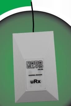
Receiver
A separate receiver provides the data stream for the Keypad and for the repeater station.
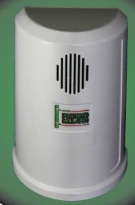
Transmitter
A Roboguard Transmitter is capable of transmitting roboguard intruder and roboguard remote alarms in response to triggering from externally connected systems.
The LED Driver unit is used to indicate visually the status of the Roboguard system. The status is indicated via an add-on LED. LED indicates Armed, Disarmed or Alarm conditions.
A handheld remote transmitter is used as a panic button and remote control for radio base stations. 4-button and 6-button versions are available.


This Australian designed and manufactured device is highly reliable and boasts the following features and benefits:
Can monitor up to 8 wireless zones
Can monitor up to 2 wired zones (sacrificing 2 wireless zones)
Can be paired with up to 20 remotes
Alarm reporting for each zone – through a User Interface
Programmable Options – easy to customize the device to suit varying site requirements
2 programmable function relay outputs
Frequency range:
150M – Roboguard Detectors
60m – PIR Detectors
40m – Remotes

Basic Stand-Alone Configuration
Programming Roboguards into the JVA RFI via the program button: arm and disarm the system via a JVA Remote or Roboguard Remote; when a Roboguard detects motion, the RFI will trigger the Siren and Strobe.
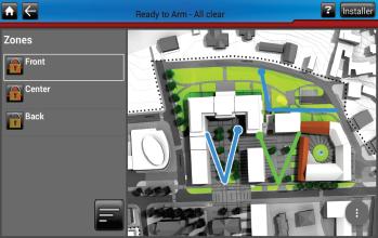
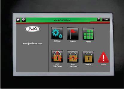
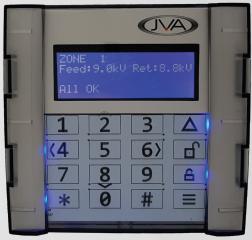
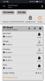
JVA Android Keypad Configuration
Program the Roboguards into the JVA RFI via the program button or the JVAAndroid Keypad. Arm and disarm the system via a JVA Remote or Roboguard Remote or JVAAndroid Keypad.
When a Roboguard detects motion, the RFI will trigger the Siren and Strobe outputs and the zone name will display on the JVAAndroid Keypad Mimic screen. Zones can be named for easier identification. If you have a JVA Energizer, this can also be linked to the system.
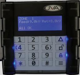
JVA 4-Line Keypad Configuration
Program the Roboguards into the JVA RFI via the program button or the JVA 4-Line Keypad. Arm and disarm the system via a JVA Remote or Roboguard Remote or JVA 4-Line Keypad. When a Roboguard detects motion, the RFI will trigger the Siren and Strobe outputs and the zone number will display on the JVA 4-Line Keypad. If you have a JVA Energizer, this can also be linked to the system.
JVA CloudRouter™ Configuration
Program the Roboguards onto the JVA RFI via the program button or the JVAAndroid Keypad or JVA 4-Line Keypad.

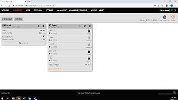

Arm and disarm the system via a JVA Remote or Roboguard Remote or JVA Android Keypad or JVA 4-Line Keypad or via the CloudRouter™ portal from a laptop, tablet or smart phone.
When a Roboguard detects motion, the RFI will trigger the Siren and Strobe and the zone will display on the CloudRouter™. You can choose what notification you should receive: SMS, Email or Facebook Messenger. Zones can be named for easier identification. If you have a JVA Energizer, this can also be linked to the system.
You can control your system from anywhere in the world as long as you have access to internet. Up to 4 users, with a 500 event log, can control and supervise the system.
WALK TEST MODE
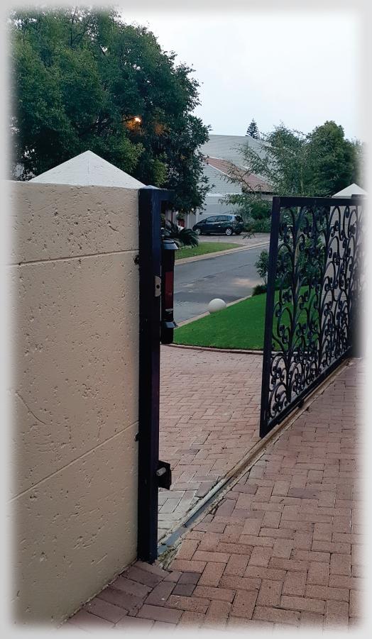
Setting up the beam array for optimal performance: After mounting your Roboguard, make sure it is detecting intruders. If its range seems very short, you will need to adjust the beams to make them level with the ground and parallel to each other. The Walk Test allows you to hear the beams as they detect and make these adjustments.
1. Remove the battery cover from the Roboguard or press and release the tamper switch. The on-board buzzer will activate for about 20 minutes before going silent again.
2. Ensure that the securing screw of both top and bottom sensor boxes is over the middle line of the adjustment slot.
3. The Roboguard will now beep once for every time the bottom sensor detects, and twice for every time the top sensor detects. You should hear three 'beeps' which means that both sensors are detecting.
4. Walk across the path cutting the beams from left to right and back again, and keep increasing the distance between you and the Roboguard. Don’t walk directly towards the Roboguard.
5. If only 1 'beep' is heard, only the bottom sensor is detecting you and the top beams are most probably set too high.
6. Top Sensor: Loosen the retaining screw. Sliding the sensor box up will lower the beam, pulling it down will raise the beam (seesaw effect). A 1mm adjustment will move the beam 1 metre up or down over 10 metres, so make only slight adjustments until you hear the beam strike you. Tighten the retaining screw
7. Bottom sensor: Follow the same instructions if only the top sensor is detecting you, this time moving the bottom sensor box.
8. Work slowly and methodically and check every beam in the pattern. Pause for 2 seconds between 'beeps' to catch the next beam.
9. Note: Move slowly; if only 1 sensor is detecting you, the Roboguard takes longer to react as it is waiting for the other sensor to detect.