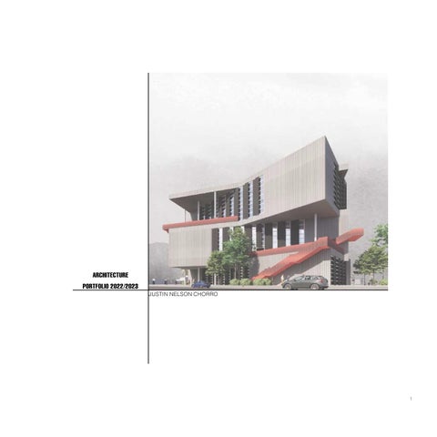
ARCHITECTURE PORTFOLIO 2022/2023 JUSTIN NELSON CHORRO
1
2
Table of Contents
Lincoln Park Co-Lab Makerspace
Pages 4-9
Santa Ana Transit District (The Connector)
Pages 10-13
Luken’s Residence Auxiliary Dweling Unit (ADU)
Pages 14-22
Mixed-Used Residential Housing Pages 24-27
3
Chapter 1: Lincoln Park Co-Lab Makerspace Justin Nelson Chorro For this first project the location’s cultural and historical significance played a crucial role in shaping the building’s design and function. Incorporating the surrounding natural elements into the building’s design, such as the use of large windows and skylights to provide ample natural light and views of the nearby park. The building’s design also allowed for a direct connection to Lincoln Park High School, which is located just a short distance away. This connection was intentional, serving as a space for learning and growth for students of all ages. By integrating the two spaces, the designers were able to create a seamless transition between education and community involvement. The site near the Plaza de la Raza played a crucial role in shaping the formal design of the building, resulting in a direct connection to Lincoln Park High School. The building’s vibrant colors, bold geometric shapes, and use of natural elements reflect the area’s rich cultural history and provide a space for learning and growth for students and the community as a whole. The building’s main formal strategy are the rotations in elevation that create unique terrace spaces, which are utilized as usable spaces. Rotating floors in architecture can create unique and dynamic terrace spaces. As you ascend the building, each floor can be rotated at a different angle, creating a variety of outdoor spaces for occupants to enjoy. This design element not only provides an aesthetic appeal but also offers functional benefits. The rotation of floors can optimize sunlight exposure and views, while also providing wind protection and privacy. Additionally, these rotating terraces can serve as green spaces or gardens, enhancing the sustainability and livability of the building. Overall, rotating floors offer a creative and practical solution for architects seeking to create distinctive and functional outdoor spaces in their designs.
4
LEGEND: 1 FAB LAB 2 PRINT LAB
A
1 B
B
2
A
SITE AREA GROUND PLAN SCALE: 1/32” = 1’-0” 100” 0” 25” 50”
5
LEGEND:
LEGEND:
A
1 CO-LAB MAKERSPACE
A
1 WOOD SHOP
2 STORAGE
2 PATIO
3 LOUNGE 3 PATIO
1 2 1 B
B
B
B
2
N
3
3
1
2 1
2
THIRD FLOOR PLAN SCALE: 1/16” = 1’-0” 25” 0”
SECOND FLOOR PLAN SCALE: 1/16” = 1’-0” 25” 0”
A
A
80’-0”
80’-0”
4
5
4
6
50’-0”
3
5
3
3
20’-0”
6
20’-0”
2
5
1
6
1
0’-0”
0’-0”
7
7 14’-0”
14’-0”
7
7 28’-0”
28’-0”
LEGEND:
LEGEND: LONGITUDINAL SECTION A SCALE: 1/16” = 1’-0” 25” 0”
6
4
50’-0”
1 FAB LAB
5 CORE
2 PRINT LAB
6 PATIOS
TRANSVERSE SECTION B SCALE: 1/16” = 1’-0” 25” 0”
1 FAB LAB
5 CORE
2 PRINT LAB
6 PATIOS
3 CO-LAB MAKERSPACE
7 STORAGE
3 CO-LAB MAKERSPACE
7 STORAGE
4 WOOD SHOP
8 PARKING
4 WOOD SHOP
8 PARKING
EAST ELEVATION SCALE: 1/16” = 1’-0” 0”
25”
NORTH ELEVATION SCALE: 1/16” = 1’-0” 0”
25”
7
8
1
2 3
4
5
6
7
8
9
10
LEGEND:
DETAILED WALL SECTION SCALE: 3/32” = 1’-0” 0”
5”
10”
20”
1 METAL FLASHING
6 CONCRETE FLOOR WITH TILE FLOOR FINISH
2 BENDHEIM VENTILATED GLASS
7 RIGID INSULATION
3 STRUCTURAL SUPPORT FOR VENTILATED GLASS 8 METAL FINISHING 4 STEEL BEAM
9 WINDOW SILL
5 WINDOW HEADER
10 METAL SHADING LOUVERS
9
Chapter 2: Santa Ana Transit District (The Connector) Justin Nelson Chorro, Eric Cubacub, Clarissa Chong For this second project the idea of using the transportation center as a gateway connecting people to the vibrant urban destination at Santa Ana brings up opportunities to bring the community together and improves pedestrian connection by introducing a variety of open spaces that unifies the three distinct main elements such as the Lifestyle, Transit, and Art. The site is organized in a manner that the transportation center is centrally located which allows travelers to get around easily to the other primary destination areas which are spread out from north to south. The Santa Ana Regional Transportation Center is close to the heart of the city. It offers mixed-mode transit services consolidated in one central location, yet the transportation center is ineffective in providing a seamless transit experience as a successful transit hub for both visitors and the community. This project aims to transform the transportation center as a gateway to connect people to different key urban destination areas of the site that offers a unique experience through public spaces. Overall, the transportation center will play a role in connecting people to their final destination enhanced through public space or a continuous destination experience that starts from the north to south that allows one to choose their own experience.
10
SANTA ANA TRANSIT DISTRICT
ERIC CUBACUB II JUSTIN CHORRO II CLARISSA CHOONG Proctor Topic Sudio Fall 2022
0’ 50’
BLVD
TA
BLVD
TIA
TIAG
SET
O STR EET
D STR FIEL
EET
GAR
EET
STR
O STR
11
N SAN
POIN
TIAG EET
EET
EET
D STR
D STR
FIEL
GAR
EET
FIEL
EET
GAR
EET
STR
O STR
STR
E 6TH STREET
E 6TH STREET
E 4TH STREET
GREEN SPACE DIAGRAM
FRONT AND BACK OF HOUSE DIAGRAM
LEGEND
LEGEND
RESIDENTIAL
LIBRARY/MEDIA TECH
OFFICES
HOTEL
BACK OF HOUSE
RETAIL
TRANSIT HUB
PARKING
GREEN SPACES
FRONT OF HOUSE
SITE
GRAND AVE
E 4TH STREET
E 4TH STREET
N EASTWOOD AVE
TERMINAL STREET
GRAND AVE
N EASTWOOD AVE
E 4TH STREET
E 6TH STREET
E 6TH STREET
TERMINAL STREET
GRAND AVE
N EASTWOOD AVE
TERMINAL STREET
GRAND AVE
N EASTWOOD AVE
TERMINAL STREET
E 4TH STREET
LEGEND
ANA
E SAN
N SAN
TIA SET
TIAG
TIA
EET
EET D STR
E 4TH STREET
BLVD
E FRUIT STREET
BLVD
E 6TH STREET
PROGRAM DIAGRAM
ANA
GRAND AVE
ANA
POIN
N SAN
SET
O STR TIAG
FIEL
GAR
EET
STR
E 6TH STREET
E 4TH STREET
EET
TA
E SAN
E 6TH STREET
TA
E SAN
E FRUIT STREET
BLVD
POIN
N SAN
TIA SET POIN E 4TH STREET
MASTERPLAN
O STR
ANA
E SAN
500’
TIAG
TA
ANA
E SAN
GRAND AVE
BLVD
E SAN
E 6TH STREET
TA
EET
GRAND AVE
GRAND AVE
ANA
BLVD
E FRUIT STREET
E FRUIT STREET
TA
ANA
E SAN
300’
N SAN
TA
O STR TIAG
BLVD
EET
ANA
O STR
EET O STR
TIAG
TIAG
N SAN
N SAN
N SAN TA
E SAN
150’
NS
TIA AN
ST
T
ET RE ST
ET RE ST
GO TIA AN NS
TIA ET INS PO
GRAND AVE
N EASTWOOD AVE
TERMINAL STREET
MASTERPLAN
E 4TH STREET E 4TH STREET
E 6TH STREET E 6TH STREET
GRAND AVE
E RE
LVD A TA
D
GO
T EE TR DS IEL RF GA
12
B NA AN ES
BLV NA A TA AN ES
E FRUIT STREET
IAGO NT N SA
O IAG NT N SA
VD A BL
A AN NT
E SA
GRAND AVE
GRAND AVE
ET RE ST
ET RE ST
VD A BL
A AN NT
E SA
E FRUIT STREET
E FRUIT STREET
VD A BL
A AN NT
VD A BL
E SA
A AN NT
E SA
ET
ET
RE
RE
ST
IA ST
IAGO
TT
NT
INSE
N SA
PO
IELD
RF
GA ET
RE
ST
FIEL
ET RE ST
ET RE IA ST TT INSE
O IAG NT N SA
PO
GAR ET RE D ST
E 6TH STREET
E 6TH STREET
E 6TH STREET
E 6TH STREET
GRAND AVE
N EASTWOOD AVE
TERMINAL STREET
GRAND AVE
N EASTWOOD AVE
TERMINAL STREET
E 4TH STREET
E 4TH STREET
E 4TH STREET
E 4TH STREET
PROGRAM DIAGRAM
GREEN SPACE DIAGRAM LEGEND GREEN SPACES
LEGEND RESIDENTIAL
LIBRARY/MEDIA TECH
OFFICES
HOTEL
RETAIL
TRANSIT HUB
PEDESTRIAN CICULATION DIAGRAM
TRANSIT CIRCULATION
LEGEND
LEGEND
SITE
OC STREET CAR
SIDEWALKS
BUS STOP
EXISTING BUILDINGS
BIKE LANE
13
Chapter 3: Mixed-Used Residential Housing Justin Chorro For this third project the purpose was to develop a detailed design proposal for a multi-family urban housing project on the subject site. Create a design to allow for commercial and residential program. The design proposed must be resolved and be able to translate to basic Type V construction techniques. Utilize a simple Type V shear wall construction technique that is common in the region and housing industry as the standard. The final part of the project will focus on the comprehensive development of a portion of the mixed-use project design that demonstrates the ability to execute a more comprehensive project. Develop wall sections, perspective sections, circulation diagrams, framing diagrams, HVAC diagrams, and plumbing diagrams The property is located at the northeast corner of the intersection at Sunset Blvd. and the Vermont Ave in Hollywood. The site currently supports a carwash and two residential buildings that will be demolished for the new development. The alley dividing the site will be relocated to the east of 4638 Prospect Ave. The relocated alley to the east is 15’ wvide and may provide vehicular access. The site is to be assumed flat in the design. The parcel is zoned C2-1D and is in sub areas B and C of the Station Area Neighborhood Plan. The FAR and the density are to be assumed as per SNAP with the 18’ podium commercial base included. The design is produced from utlizing the outline of the site to create structures that allow for the usage of program. The program is seperated with the public program being the first two floors and the private program closed to the residents of the building. The building consists of corridors that are facing the Hollywood sign at the top three floors of the building. Within these corridors are lounge areas that allow for the implementation of public and private space within the project. Architecture unit plans, plans, sections, axons, and renders were developed.
14
N VERMONT AVE
HO
LL YW
OO
BL
D
PROSPECT AVE
D
SITE PLAN SCALE 1/8” = 1’ 5’ 10’
20’
15
A
A
STUDIO
CAFE
PARKING
2 BEDROOM STUDIO
STUDIO
PODIUM
GYM
EFX546
EFX546
EFX546
EFX546
EFX546
EFX546
EFX546
EFX546
2 BEDROOM
STUDIO B
B
B
B 2 BEDROOM
STUDIO
GIRLS RESTROOM MENS RESTROOM
2 BEDROOM STUDIO
PARKING
LOBBY
1 BEDROOM
A
A
1 BEDROOM
STUDIO
2 BEDROOM FIRST FLOOR LEVEL PLAN SCALE 1/8” = 1’ 5’ 10’ 20’
SECOND FLOOR LEVEL PLAN SCALE 1/8” = 1’ 5’ 10’ 20’
A
A
BACLONY
STUDIO 1 BEDROOM
2 BEDROOM
2 BEDROOM STUDIO
1 BEDROOM STUDIO
BACLONY
2 BEDROOM
2 BEDROOM
BEDROOM STUDIO B
B
1 BEDROOM
B
BACLONY
B
2 BEDROOM
2 BEDROOM
CL. LIVING ROOM
STUDIO
BEDROOM LIVING ROOM 1 BEDROOM
2 BEDROOM
BATHROOM
2 BEDROOM STUDIO
CL. LIVING ROOM 1 BEDROOM
A
BEDROOM
1 BEDROOM
A
1 BEDROOM
STUDIO
BATHROOM
1 BEDROOM
KITCHEN
CL.
STUDIO
2 BEDROOM
KITCHEN
KITCHEN BATHROOM
BATHROOM
CL.
2 BEDROOM
THIRD FLOOR LEVEL PLAN SCALE 1/8” = 1’ 5’ 10’ 20’
FOURTH FLOOR LEVEL PLAN SCALE 1/8” = 1’ 5’ 10’ 20’
2 BEDROOM PLAN SCALE 1/4” = 1’ 1’
A
4’
1 BEDROOM PLAN SCALE 1/4” = 1’ 8’
1’
4’
STUDIO PLAN SCALE 1/4” = 1’ 8’
1’
4’
8’
A
TOWNHOUSE
TOWNHOUSE
TOWNHOUSE
TOWNHOUSE
LOUNGE TOWNHOUSE
TOWNHOUSE
B
B
LIVING ROOM
CL.
B
B TOWNHOUSE
TOWNHOUSE
CL. BACLONY BEDROOM
TOWNHOUSE
TOWNHOUSE
BEDROOM
KITCHEN
BATHROOM CL.
BATHROOM
A
A
TOWNHOUSE LOWER PLAN SCALE 1/4” = 1’ FIFTH FLOOR LEVEL PLAN SCALE 1/8” = 1’ 5’ 10’ 20’
16
SIXTH FLOOR LEVEL PLAN SCALE 1/8” = 1’ 5’ 10’ 20’
1’
4’
8’
TOWNHOUSE UPPER PLAN SCALE 1/4” = 1’ 1’
4’
8’
BATHROOM
BACLONY
ROOF PARAPET
BATT INSULATION
FINISH FLOORING
DOUBLE TOP PLATE
SUBFLOOR
BOTTOM PLATE
BALCONY
FLOOR JOISTS
GLASS GUARDRAIL
VERTICAL ALUMINUM LOUVER
HORIZONTAL ALUMINUM SUPPORT
PERSPECTIVE SECTION NTS
17
TOP OF ROOF 83’-0”
SIXTH LEVEL 70’-0”
FIFTH LEVEL 58’-0”
FOURTH LEVEL 45’-0”
THIRD LEVEL 32’-0”
SECOND LEVEL 19’-0”
FIRST LEVEL 0’-0”
NORTH ELEVATION SCALE 1/8” = 1’ 5’ 10’ 20’
TOP OF ROOF 83’-0”
SIXTH LEVEL 70’-0”
TOWNHOUSE FIFTH LEVEL
%<UserText("block", "XSIZE", "ZSIZE", "ZSIZE", "YSIZE", "YSIZE", "0.0000")>% "XSIZE", "815.5826")>% "1666.9595")>%
58’-0”
1 BEDROOM
2 BEDROOM FOURTH LEVEL %<UserText("block", "XSIZE", "ZSIZE", "ZSIZE", "YSIZE", "YSIZE", "0.0000")>% "XSIZE", "815.5826")>% "1666.9595")>%
%<UserText("block", %<UserText("block", %<UserText("block", "XSIZE", "YSIZE", "ZSIZE", "XSIZE", "YSIZE", "ZSIZE", "1666.9595")>% "815.5826")>% "0.0000")>%
45’-0”
STUDIO
2 BEDROOM THIRD LEVEL %<UserText("block", "XSIZE", "ZSIZE", "ZSIZE", "YSIZE", "YSIZE", "0.0000")>% "XSIZE", "815.5826")>% "1666.9595")>%
%<UserText("block", %<UserText("block", %<UserText("block", "XSIZE", "YSIZE", "ZSIZE", "XSIZE", "YSIZE", "ZSIZE", "1666.9595")>% "815.5826")>% "0.0000")>%
32’-0”
STUDIO
2 BEDROOM SECOND LEVEL
%<UserText("block", "XSIZE", "ZSIZE", "ZSIZE", "YSIZE", "YSIZE", "0.0000")>% "XSIZE", "815.5826")>% "1666.9595")>%
%<UserText("block", %<UserText("block", %<UserText("block", "XSIZE", "YSIZE", "ZSIZE", "XSIZE", "YSIZE", "ZSIZE", "1666.9595")>% "815.5826")>% "0.0000")>%
19’-0”
GYM
FIRST LEVEL 0’-0”
SECTION A SCALE 1/8” = 1’ 5’ 10’
18
20’
PARKING
WEST ELEVATION SCALE 1/8” = 1’ 5’ 10’ 20’
WEST ELEVATION SCALE 1/8” = 1’ 5’ 10’ 20’
TOWNHOUSES
TOWNHOUSES
2 BEDROOM
2 BEDROOM 2 BEDROOM
2 BEDROOM 2 BEDROOM
2 BEDROOM 2 BEDROOM
2 BEDROOM
2 BEDROOM
2 BEDROOM 2 BEDROOM
2 BEDROOM 2 BEDROOM
2 BEDROOM 2 BEDROOM
2 BEDROOM
2 BEDROOM
2 BEDROOM 2 BEDROOM
2 BEDROOM 2 BEDROOM
2 BEDROOM 2 BEDROOM
2 BEDROOM
CAFE
CAFE
SECTION B SCALE 1/8” = 1’ 5’ 10’
20’
SECTION B SCALE 1/8” = 1’ 5’ 10’
GYM
GYM
20’
19
SILL PLATE RIGID INSULATION
FLOOR JOISTS
BATT INSULATION
GLASS GUARDRAIL
DOUBLE TOP PLATE
BALCONY
BOTTOM PLATE
CONCRETE PODIUM ANCHOR
WINDOW SILL
EARTH
WALL SECTION A SCALE 1/2” = 1’ 1’
20
2’
4’
8’
SILL RIGID INSULATION 2x10 FLOOR JOISTS
CONCRETE PODIUM
DOUBLE TOP PLATE
BATT INSULATION
BOTTOM PLATE EARTH
WALL SECTION B SCALE 1/2” = 1’ 1’
2’
4’
8’
21
22
23
Chapter 4: Luken’s Residence Auxiliary Dweling Unit (ADU) Justin Nelson Chorro For this fourth and final project the objective was to design an ADU on a residential site with zoning that allows for an accessory unit. Develop a freestanding structure to accomodate the program. Demonstrate the ability to organize a residential environment horizontally and vertically to accomodate functional needs, privacy, views, acees to the site and environment, natural light/ ventilation. The site is the SE corner of the property located at 3425 West 27th Street, Los Angeles. It is currently an unpaved parking area on the site of the Lukens hoouse designed by Raphael Soriano. The site fronts onto 27th street and an alley to the east. There is a +/-3’ grade seperation (lower) between the ADU site and the remainder of the Lukens House site. The design is introduced from extruding half of the building in plan to allow for the development of the second floor. The program is seperated by floor with the first floor consisting of public program and the second floor consisting of private program. A rooftop patio was created by excavating the first floors roof. Architecture plans, sections, axons, and renders were developed.
24
AXONS SCALE 1/4” = 1’ 1’
4’
8’
25
26
SECTION A SCALE 1/8” = 1’ 5’ 10’
20’
SECTION A SCALE 1/8” = 1’ 5’ 10’
20’
SECTION B SCALE 1/8” = 1’ 5’ 10’
20’
SECTION B SCALE 1/8” = 1’ 5’ 10’
20’
27