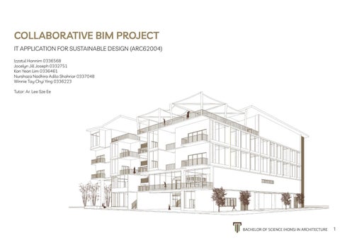
COLLABORATIVE BIM PROJECT IT APPLICATION FOR SUSTAINABLE DESIGN (ARC62004) Izzatul Hannim 0336568 Jocelyn Jill Joseph 0332751 Kan Yean Lim 0336461 Nurshaza Nadhira Adila Shahriar 0337048 Winnie Tay Chyi Ying 0336223 Tutor: Ar. Lee Sze Ee
BACHELOR OF SCIENCE (HONS) IN ARCHITECTURE
1
TABLE OF CONTENTS
01
INTRODUCTION
02
CASE STUDY
03 04
05
1.1 Project Introduction ……………………………………………………………………………………………………………………..….... 4 1.2 Introduction to BIM (Building Information Modelling) ............................................... 5-6 1.2.1 Importance of BIM ……………………………………………………………………………………………………………. 7 1.2.2 Pros and Cons of BIM ……………………………………………………………………………………………………… 8 1.2.3 BIM Tools and Process …………………………………………………………………………………………………... 9-10 1.3 Introduction to Common Data Environment (CDE) ………………………………………………….. 11 1.3.1 Cloud Collaboration (BIM 360) ………………………………………………………………………………... 12 1.4 BIM Conclusion ……………………………………………………………………………………………………………………………………... 13 1.5 Methodology ………………………………………………………………………………………………………………………………………….. 14
2.1 Roles & Responsibility ………………………………………………………………………………….…………………………..…..… 16-18 2.2 Design Description …………………………………………………………………………………………………………………………….. 19 2.3 Project Management Plan ………………………………………………………….……………………………………………..… 20 2.3.1 Project Milestone …………………………………………………………………………………..…………………...……... 21-22 2.3.2 Schematic Plan and Sketches ………………………………….……………………….…………….……….. 23 2.3.3 Gantt Chart ………………………………………………………………………………………….…………………….….……... 24 2.3.4 Coordination Platform …………………………………………………………….…………………….…….……….. 25 2.3.5 Master Planning - Site Analysis and Precedent Studies & Design Concept & Programming Layout.……………………………………………......... 26 2.3.6 Master Planning _ Room Layout & Building Energy Proposal…......... 27 2.3.7 Schematic Design……………………………………………………………………………………………………………….. 28 2.3.8 Design Finalisation ……………………………………………………………………………………………………………. 29-30 2.3.9 Documentation …………………………………………………………………………………………….……………………... 31 2.3.10 Building Analysis ……………………………………………………………………………………………………………... 32 2.3.11 Modeling Process ……………………………………………………………………………………………………..…….. 33-34 2.4 Information Quality Assurance and Control …………………………………………………….…………….. 35 2.4.1 Level of Development (LOD) ………………………………………………………………………….………….. 35-37
REFLECTION …………………………………………………………………………………………………………………………………...… 39-40 APPENDIX
4.1 Project Correspondence, Minutes & Internal Memos ………………………………….………….. 42-46 4.2 Stakeholders Objectives ………………………………………………………………………………………………………..………… 47 4.3 Schedule of Finishes ……………………………………………………………………………………………………………….….………. 48-57 4.4 Query Approval ……………………………………………………………………………………………………………………………….…….. 58 4.5 Building Cost ………………………………………………………………………………………………………………………………………..…… 59 4.6 Building Efficiency ……………………………………………………………………………………………………………………………..…. 60 4.7 Architecture Drawing ………………………………………………………………………………………………………………………... 61-71 4.8 Clash Report ……………………………………………………………………………………………………………………………………………... 72-73 4.9 Timeline COnstruction Process …………………………………………………………………………………………………… 74
REFERENCE
2
1.0 INTRODUCTION 1.1 Project Introduction 1.2 Introduction to BIM (Building Information Modelling) 1.2.1 Importance of BIM 1.2.2 Pros and Cons of BIM 1.2.3 BIM Tools and Process 1.3 Introduction to Common Data Environment (CDE) 1.3.1 Cloud Collaboration (BIM 360) 1.4 BIM Conclusion 1.5 Methodology
3
01
INTRODUCTION
1.1 Project Introduction Project Requirements : 1. Maximum land size: as per land given by client. 2. To develop preliminary design in compliance with LOD 200 requirements. 3. Use appropriate BIM authority tools (Autodesk Revit, Autodesk Naviswork) to collaborate the informations. Client :
Taylor’s University SDN. BHD.
Stakeholders :
Quantity Surveyor
Interior Designer
Hotel Management
Creative Media Marketing
Designing a 5 storeys hotel :
adapting to the sustainable features
collaborative practice using the BIM methods and procedure.
PROJECT AIM Analysed the workflows , project requirement technical issues and the consideration of a collaborative project.
Applying the skills of BIM technology to reduce the risk or clashes occur among collaborative.
Take in communication and collaborative skills by identifying and understanding on the roles and responsibility of each members during the design planning.
4
01
INTRODUCTION
1.2 Introduction to BIM (Building Information Modelling) What is BIM? BIM (Building Information Modelling) is a process that improves how architects and engineers design and construct buildings. Architects can create a digital 3D model of the building using the BIM authoring tool, allowing them to see a representation of how it will look and function. Authoring
Plan
Extract Building Model
Process
Informations
+
A 3D model process to organise the work flow
Collaborate & interact with other project stakeholders
Authoring
Manage / Coordinate
Authorise
Design
Extract Building Model
Example of Door
It is a process of providing the information using the technologies digital software or tools to create a 3d model design with every detail of the building.
5
01
INTRODUCTION
1.2 Introduction to BIM (Building Information Modelling) What is BIM? BIM (Building Information Modelling) is a process that improves how architects and engineers design and construct buildings. Architects can create a digital 3D model of the building using the BIM authoring tool, allowing them to see a representation of how it will look and function. Rating
Authorise
Building Model
Size Material
Informations
Door Type
Manage
+
Method Statement
Location
A 3D model process to organise the work flow
Collaborate & interact with other project stakeholders
Manage / Coordinate
Position
Building Model Planning
Construct
Design Constructability
Maintenance Analyse
Extract
Building Model
Scheduling
Visualisation
Performance
Construct Clash Detection
Maintenance
6
01
INTRODUCTION
1.2.1 Importance of BIM
Breaking limitation of traditional modelling by providing more function.
Allows design and construction teams to work more efficiently.
Why BIM? Allows them to capture the data they create during the process to benefit operations and maintenance activities.
Essay access for modification.
The model can be used for analysis to explore design options and to create visualizations that help stakeholders understand what the building will look like before it's built.
7
01
INTRODUCTION
1.2.1 Pros and Cons of BIM
● ●
PROS
CONS
Better planning and design
Incompatibility with partners
It allow to visualise a complete building before the construction process start. Have the advantage of having information for the best outcome of building.
Chances of having partners that may not use BIM and may not be able to use the given models.
●
Legal issues
Fewer rework ● ●
It allow to see potential problem areas and fix them before the error happen in real world. Reduce the need for cost revision.
●
Savings on materials ●
Able to track and provide detailed information hence less likely to order more than needed.
Cost of software ●
Support for prefabrication ●
Allows you and your partners to more easily prefabricate components of the project offsite, which saves time and money.
The legal ramifications of using BIM software have not yet been extensively tested.
BIM software requires a substantial investment in new technology.
Lack of experts ● ●
There are limited numbers of experts working in the field. May require an additional investment in training and education.
8
01
INTRODUCTION
1.2.3 BIM Tools Building Design Architects and engineers are creating high-performing building designs
Revit
FormIt Pro
Civil 3D
Infrastructure
Construction
Use connected workflows to improve predictability and profitability
Evaluate design intent while also communicating construction intent
InfraWorks
AutoCAD
Revit
Create precise 2D construction documentation
Use BIM tools to create detailed, reliable construction models
Design and document buildings with Building Information Modelling
Sketch early stage design concepts in 3D. Connects with Revit
Design, optimize and document roadway, bridge, and rail projects
Dynamo Studio
Insight
Revit
ReCap Pro
Navisworks Manage
ReCap Pro
Integrate vertical structures with horizontal infrastructure designs
Generate accurate existing conditions with point cloud or mesh
Combine data from multiple trades to better control project outcomes
Design in-context with reality capture and 3D scanning
Autodesk Docs
Automate design task and explore design concepts in Revit
Conduct energy and building performance analysis
3ds Max
AutoCAD
AutoCAD
Visualize high-quality architectural renderings
Create 2D CAD designs that can bring to Revit
Streamline drafting with AutoCAD and industry specialized toolsets
Lay out conceptual roads, analyze traffic and visualize designs
Simplify collaboration with a cloud-based common data environment
9
01
INTRODUCTION
1.2.3 BIM Process
Plan
Design
Build
Operate
Inform project planning by
During this phase, conceptual
During this phase, fabrication
BIM
begins using BIM specifications. Project construction logistics are shared with trades and
operations and maintenance of finished assets. BIM data can be used down the road for
contractors to ensure optimum timing and efficiency.
cost-effective renovation efficient deconstruction too.
design, analysis, detailing and documentation are performed. The preconstruction process
combining reality capture and real-world data to generate context models of the existing
begins using BIM data to inform
built and natural environment.
scheduling and logistics.
2D Drawing
2D CAD
3D CAD
Paper drafting informs
Design drawn on the
3D
of blueprints
computer through software application
better visualisation
2D CAD/ 3D MODEL
model
3D for
With
building information provided for the stakeholders
Incorporated
carries
over
to
or
5D
4D integrated
data
with
the timeline on construction process
BIM - BASED PROCESS
Incorporated
with
the cost on each process during the construction process
10
01
INTRODUCTION
1.3 Introduction to Common Data Environment (CDE)
BIM 360 is a unified platform connecting your project teams and data in real-time, from design through construction, supporting informed decision-making and leading to more predictable and profitable outcomes.
WORKFLOW Construction Management
Centralized Management
Project Lifecycle Management
Innovation
11
1.3.1 Cloud Collaboration (BIM 360) CONSTRUCTION MANAGEMENT
CENTRALIZED MANAGEMENT
Reduce risk, improve Quality and deliver projects on time and on budget
Accelerate and improve decision making and predict project outcome
Quality Management
RFIs and Submittals
Safety Management
Constructability
Document Management
Coordination
Design Collaboration
Data and Analysis
PROJECT LIFECYCLE MANAGEMENT
INNOVATION
From design to construction within one platform
Increase predictability and profitability while driving innovation in the business
Constructability
Design Collaboration
Data and Analysis
RFIs and Submittals
Coordination
Quality Management
Safety Management
Document management
12
01
INTRODUCTION
1.4 BIM Conclusion
BIM 360
Prefabrication
Virtual Simulation
Data Accessibility
Lessen accidents at job sites
Higher building quality
Transparency from ideas to construction
Collaborative Design
Coordinated Approach
Virtual Model
Better Data Quality
Higher building efficiency
Faster project delivery
Earlier level conflict and error detection
Lifecycle building management
13
01
INTRODUCTION
1.5 Methodology BIM Methodology involves the collaboration of project management through a 3D digital model. It helps shorten the time span for the designing and the production process, hence it can gradually reduce the costs of the project. By using BIM, it allow the quality of the task to be improve for the architecture and construction. Through system optimization and streamlining phases of the project to achieve a more linear and collaborative workflow within a project team, BIM has made some changes that have taken place in the working and architectural project development methods.
Coordination
Different software is used to create different objects-and so, they can be joined together to find out possible conflicts. Anyway, the perfect solution would be the usage of models connected together since the beginning, such as, technologies of cloud computing.
Extraction of 2D sketch
During every moment in the design process, it is possible to extract from 2D sketches from the model and the designer can make sure that they are always up to date.
Communication and visualization
The 3D model is particularly useful for a deeper understanding of the planning solution, not only for the designers but also for all the stakeholders involved that are not familiar with the work of the experts. It also possible to work through the model.
Guarantee on costs
The control of the project is one of the most enriching values of BIM, because it allows us to spot and work out problems in the design phase instead of during the construction phase. Due to the control tools of the model, it is feasible to favor the building with rule-based software validation that relies on information that have been defined according to the BIM requirements.
Analysis
BIM can help architects in the simulation of the performance and life of the building. A different analysis can be run such as structural analysis, energetic analysis, sound and lights analysis.
Construction
BIM can also be adopted for the design of the security system and to study the layout of the construction site with a focus on synergies within the surrounding areas. Additionally, the simulations can be powerful for example to master the sequence of installation of the different components, the planning of the production, the building inspections and to visualize the construction phase.
14
2.0 CASE STUDY
2.1 Roles & Responsibility 2.2 Design Description 2.3 Project Management Plan 2.3.1 Project Milestone 2.3.2 Schematic Plan and Sketches 2.3.3 Gantt Chart 2.3.4 Coordination Platform 2.3.5 Master Planning - Site Analysis and Precedent Studies & Design Concept & Programming Layout 2.3.6 Master Planning _ Room Layout & Building Energy Proposal 2.3.7 Schematic Design 2.3.8 Design Finalisation 2.3.9 Documentation 2.3.10 Building Analysis 2.3.11 Modeling Process 2.4 Information Quality Assurance and Control 2.4.1 Level of Development (LOD)
15
INTRODUCTION - ORGANIZATIONAL CHART
PROJECT LEADER KAN YEAN LIM
DESIGN MANAGER
BIM MANAGER
WINNIE TAY CHYI YING NURSHAZA NADHIRA ADILA JOCELYN JILL
ARCHITECT
STRUCTURE ARCHITECT
WINNIE TAY CHYI YING
ARCHITECTURAL MATERIAL
NURSHAZA NADHIRA ADILA
UBBL
IZZATUL HANNIM
IZZATUL HANNIM
KAN YEAN LIM
LANDSCAPE ARCHITECT
CORE STRUCTURE
NURSHAZA NADHIRA ADILA
JOCELYN JILL
SUSTAINABILITY CONSIDERATIONS IZZATUL HANNIM
FLOOR PLANS
WINNIE TAY CHYI YING
ELEVATIONS
BIM COORDINATOR / BIM MODELLER (ARCHITECTURAL)
KAN YEAN LIM
WINNIE TAY CHYI YING
SECTIONS
BIM COORDINATOR / BIM MODELLER (STRUCTURAL)
CLASH DETECTION MANAGER KAN YEAN LIM
NURSHAZA NADHIRA ADILA
KAN YEAN LIM
COLUMN / SHEAR WALL
SECTIONS INDICATION
WINNIE TAY CHYI YING
IZZATUL HANNIM
WALLS / FLOOR / STAIRCASE / RAILING / DOOR / WINDOW WINNIE TAY CHYI YING
ROOF / CEILING / RAMP NURSHAZA NADHIRA ADILA
BEAMS / FOUNDATION / ROOF TRUSS NURSHAZA NADHIRA ADILA
COURTYARD / LANDSCAPING JOYCELYN JILL
16
02
CASE STUDY
2.1 Roles & Responsibility ROLE
TECHNICAL
PROCESS
PEOPLE
BIM MANAGER
Ensure software is installed and operable.
Assist in development of BIM Management Plan or BIM Execution Plan.
Implementing appropriate training and upskilling to ensure effective information delivery.
Set up and maintain CDE.
Ensure compliance of CDE and BIM.
Analyze model information to ensure it fits for the requirement.
Manage the Management and Quality Control of model distribution.
Report clash detection and creates reviews.
Coordinate management file processes.
Provide BIM point to other subordinates. Hold technical meetings with BIM technicians.
Lead in preparation of project outputs. Compile composite models. STRUCTURAL BIM COORDINATOR
Checking structural part of drawing & model are up to date and correct. Foundations, auger cast piles, grade beams, etc. Steel beams and columns. Model the correct bridging locations.
BIM workflow and ensuring that any Receive an approved steel model and incorporate potential issues during modelling, that information into the coordination model for all clash detection and data conversion trades to coordinate with. is dealt with efficiently. Review and verify within the contract documents. Verify that all trades avoid these areas. Review and verify within the contract documents.
17
02
CASE STUDY
2.1 Roles & Responsibility
ROLE
TECHNICAL
PROCESS
PEOPLE
ARCHITECTURAL BIM COORDINATOR
Wall types
Verify the dimensions shown are real and not “text” for visual purposes.
Review and verify within the contract documents.
Fire rated wall locations Chase locations Ceilings
The model must have the correct content to do proper virtual coordination.
Different types True dimensions STRUCTURAL BIM MODELLER
Work with both internal and external team members in the development of construction documents.
Model based on 2D design drawings and other models.
Work with various disciplines and external parties to create/develop Building Information Model based on 2D design drawings and other models.
Identify all issues of 2D drawings and compose the RFIs to coordinate with the client.
Work side by side with teams in-house and external teams to complete BIM projects.
ARCHITECTURAL BIM MODELLER
Set up, prepare and produce structural BIM Models using Autodesk Revit Structure for contract documents and coordination.
Prepare submission drawings with presentation format to authorities.
Work together with the Project Management team to work on projects.
CLASH DETECTION MANAGER
Carry clash detection on the revit model
Carry clash test and generate report on the clash detected that need to be solve.
Review and work with the BIM manager and BIM coordinator to ensure clashes are fix
18
02
CASE STUDY
2.2 Design Description
The 5-storeys hotel was designed based on a concentric layout with an open spaces where the central courtyard helps enhance the interaction between spaces. It also plays with openings which allows ventilation to occur across the building. It mainly uses columns and beams as the core structure with curtain wall facade inserted between the columns and a mixture of shear wall as the secondary structure.
Building Specification Pile Foundation : 2006x2006x889mm Column : 800x500mm Beam : 300mmx500mm Shear Wall : 200mm Interior Wall : 150mm
19
PROJECT MANAGEMENT
02 CASE STUDY 02 2.3 Project Management Plan
PROJECT REQUIREMENT
MASTER PLANNING (BAT-BIA-BQS-BIHM_BDCM)
CONCEPTUAL DESIGN -Site Analysis -Design Concept -Programming Layout -Room Layout -Building Energy Proposal
DESIGN DEVELOPMENT (BAT-BIA-BQS-BIHM_BDCM)
DOCUMENTATION (BAT-BIA-BQS)
SCHEMATIC DESIGN -Programming Layout -Preliminary Design Proposal -Building Structure Proposal -Building Services Proposal -Schematic Interior design
WORKING DRAWINGS -Schedule of Finishes -Door Schedule -Window Schedule -Building Plans -Submission Approval
DESIGN FINALISATION -Finalization of Design Proposal -Detailed Schematic Drawings -Visualisation Drawings (sections drawings) -Detailed Structural Plans -Landscape Proposal Plans
BUILDING ANALYSIS -Clash detection -Reporting Clash -Final Drawings -Final documents compilation
HANDLING OVER
20
02
CASE STUDY
2.3.1 Project Milestone WEEK 2
CONCEPTUAL DESIGN / MASTER PLANNING
WEEK 3
WEEK 4
SCHEMATIC DESIGN
DESIGN DEVELOPMENT
Initial design scheme based on precedent studies on hotel layout.
Delegate task according to roles and responsibilities.
Assign roles and responsibilities.
Programmed and spatial layout arrangements.
Manage and analyse the information & requirement from. Implementation and analysation on conceptual massing in relation to the sustainability features and the building settings. Initial collaboration plan formed.
Discuss amendment of services layout. Modellers generate initial architectural plans in Revit file.
BIM MANAGER ● Approves services layout. ● Prepare and analyse visualisation of layout to fit for project purpose. ● Creates Project file. ● BIM Manager prepare for structural system planning. BIM COORDINATOR ● Ensure and provide guidelines for team on project layout and rules. ● Coordinate meeting among subordinates. ● Allocate and coordinates BIM tasks within own team. ● Coordinating start report draft. BIM MODELLER ● Create detail BIM Modelling Content. ● Follow up from Architecture BIM Manager for revised project file to BIM Manager. ● Follow up from subordinates on revised layout.
21
02
CASE STUDY
2.3.1 Project Milestone WEEK 5
DESIGN DEVELOPMENT
BIM MANAGER ● Lead in project output preparations. BIM COORDINATOR ● Execute clash detection and reports. ● Guarantee functionality of merged model / integration of design model on team contribution . BIM MODELLER ● Create detail BIM Modelling Content. ● Follow up from Architecture BIM Manager for revised project file to BIM Manager. ● Follow up from subordinates on revised layout.
WEEK 6
CONSTRUCTION DOCUMENT
WEEK 7
CONSTRUCTION DOCUMENT
BIM MANAGER ● Assemble formed models ● Lead in project output and data preparation ● Coordinates management processes files
Finalised the model, compiling slides, reports and reflection of each members
BIM COORDINATOR ● Execute clash detection and reports ● Guarantee functionality of merged model / integration of design model on team contribution
Finalised report and project files to be presented and shared to client.
Include the updated BIM execution plans into report
Reflection report on the whole project and collaboration effectiveness
BIM MODELLER ● Produce accurate drawings and data of construction details based on the BIM platform
22
02
CASE STUDY
2.3.2 Schematic Plan and Sketches
guest hotel rooms -suite -deluxe king -deluxe single -deluxe twin/queen
-lobby -lift -cafe -fire staircase -M&E -storage -guest hotel rooms -courtyard -reception -lounge / activities spaces -meeting room
Column as structural element
Open floor plan layout on the ground floor Concentric circulation on upper floor
23
PROJECT MANAGEMENT
02 CASE STUDY 02 2.3.3 Gantt Chart
24
02
CASE STUDY
2.3.4 Coordination Platform COLLABORATION
COORDINATION
COORDINATION / AUTHORISATION
BAT TEAM
BAT TEAM
( Clash Analysis )
( Design & Cost Consultant ) BIA & BQS
BIM Collaborate Pro Naviswork Manage 2020
Autodesk Revit 2020 M
-BDC
HM S-BI Q B BIA
BAT-
o eting
e al M ener
-Up atch C s s gre n Pro
)
(G Provide platform for a better design collaboration and ensuring the latest info is given.General meeting is held online as not all stakeholders have the skills on technology.
Project Leader / BIM Manager Stakeholders
Microsoft Teams
ONLINE MONITORING
OFFLINE MONITORING Provide a reminder for the stakeholders to check on the updates and a record to refer on the issues and discussions.
BAT TEAM
Meeting Recording
COLLABORATION
BAT
BQS
BIA
BIHM
BAT TEAM
BAT-BIA-BQS-BIHM-BDCM
( Discussion on project )
( Weekly Progress )
Project Leader -BIA-BQS-BIHM-BDCM
( Informing for any updates or a direct platform for enquiries and questions )
BDCM
Multiple Folders
Google Drive
25
02
CASE STUDY
2.3.5 Master Planning - Site Analysis and Precedent Studies & Design Concept & Programming Layou (week 2) Site Analysis and Precedent Studies
Design Concept COLLABORATION
Project Leader : Holding meeting with the stakeholders Refer to Appendix 4.1 (session 1)
Site Analysis( positive and negative views)
All recording and progress from stakeholders are uploaded to Google Drive.
COORDINATION
BIM Manager : Compiling the requirement from the stakeholders and rearrange for a design concept ro prevent clashing of design on later stage
Programming Layout Architect : Discussion on design layout AUTHORISATION
Design Manager : Design exploration based on concept and programmes given with the references of site analysis
Precedent study on hotel layout and spatial arrangement
BAT TEAM : Analyse and gain better understanding on the site context as well as the structure of a BOUTIQUE HOTEL
ISSUES :
SOLUTIONS :
-Time Restriction on Zoom Meetings -Difficulties on approaching the stakeholders after meeting -Communication issues on understanding the requirement of every stakeholders -Difficulties in delivering the concept to other stakeholders
-Switching to Microsoft Teams -Allow offline communication via WhatsApp / calls -Catching up an referring back the progress info uploaded in Google Drive -Readjust the delivery method through sketches / images / photomontage
26
02
CASE STUDY
2.3.6 Master Planning - Room Layout & Building Energy Proposal (week 3)
Building Energy Proposal
Room Layout BIHM COLLABORATION
COORDINATION
Landscape Architect : Research and Integration of Sustainable Features into the Design
Design Manager
Landscape Architect
1 Atrium
BIM MANAGER
Design Manager : Discussion among the BAT DESIGN TEAM with the guidance on room dimension and suggestion from BIHM
2 Courtyard COORDINATION Unit type in each floor
l
Deluxe Single room (37-45 m2)
Deluxe Queen / King room (32-50 m2)
Deluxe Twin room (32-40 m2)
Suite (70-100 m2)
(9 x 4.5 m = 40.5 m2) - (2 / 3 rooms)
(9 x 5.5 m = 49.5 m2) - (4 rooms)
COLLABORATION
(9 x 10 m = 90 m2) - (1 / 2 rooms)
ISSUES :
SOLUTIONS :
-Difficulties on visualising the room layout -Difficulties on work distribution as only one man be able to work on the digital model -Waste space created due room dimension give and the room layout arrangement -Difficulties from BQS on conceptualising the building
-Retracting information from BIHM on the survey study carried by them -Allocating the workload to information compiling , modeling , and drawings /sketches -Getting advice from BQS on layout arrangement -Support the draft sketch with to scale digital drawings and concept modelfor better visualisation
Refer to Appendix 4.1 (session 2-3)
(9 x 4.5 m = 40.5 m2) - (4 / 5 rooms)
Maximise Usage of Natural Light
Lower Down Indoor Temperature
Design Manager : Integration with landscape to provide section for better visualisation
BIM Manager
Project Leader : Meeting with Stakeholders to Verify the Design and Progress Catching Up
27
02
CASE STUDY
2.3.7 Schematic Design (week 4-) BQS
Preliminary Design Proposal
Building Services & Structure Proposal
Architectural BIM Coordinator
Structural BIM Coordinator
Design Manager : Adjustment and consideration on design layout
Schematic Interior Design
Refer to Appendix 4.1 session (4)
BIM Manager
Via Microsoft Teams
Refer to Appendix 4.1 session (5)
Project Leader : Advice from BQS on design layout, fire escape and services consideration
COLLABORATION Meeting with Stakeholders : Discuss on schematic interior spaces proposal
Meeting with BIA on Spatial Layout & request for the interior programme requirement
Refer to Appendix 4.1 session (6)
COLLABORATION
ISSUES :
SOLUTIONS :
-Disagreement on courtyard layout from BQS due the cost and efficiency consideration -Uneven workload as only one person manage to work on the digital model at a time -Difficulties on visualising the interior spaces provided leading to wrong function allocation on wrong spaces
-Discuss to provide a more usable courtyard that benefit both parties -Carrying out other progress that helps to support the digital mode -Creating montage with plan allocated to demonstrate a walkthrough journey
28
02
CASE STUDY
2.3.8 Design Finalisation (week 4-5)
PROJECT LEADER
BIM MANAGER : Deliver the info and modification to be done
BIM COORDINATOR : Building model according according to the information and suggestion given
Roof Structure Proposal Insertion of AHU level and roof proposal
ARCHITECT : Distribute the task among to provide orthographic for visualisation
Refer to Appendix 4.1 session (7 )
Detail Schematic Drawings
PROS :
-The application of BIM 360 helps improve the work progress and even workload distribution -Stakeholders up to date for the latest model
ISSUES : -Technical issue on synchronising as a beginner to the BIM 360 -Forgot to release element leaving a difficulties for other to edit -Distraction from other stakeholders on model design -Not all stakeholders have the skills on using the software
Exploring and inviting team member to explore the new software. The new software helps in separating the task faster and easier.
SOLUTIONS :
Refer to Appendix 4.1 session (8 )
-Project leader researching and fixing on the issue and guide the team member -Send and request to the person to remind that person to relinquish -Adjust the setting according to the need of other stakeholders to prevent from clashing occur in model -Remain offline communication platform and update on both platform
29
02
CASE STUDY
2.3.8 Design Finalisation (week 4-5) BIM Modeller (architectural & structural)
Project Leader
Checking issue and create report for action to be taken
Synchronised and publish to cloud
Ensure the model is uploaded
Create an account and open a project template Ensure is accessible by skate holders and synchronise by team member
Create workset in Revit to and allocate task according to roles to prevent clashing
Inviting member and related stakeholders with the accessible settings fix according to the roles
BIM Manager
30
02
CASE STUDY
2.3.9 Documentation (week 5) Sections and ELevations
Schedules ( door, window & door)
BQS : Taking off the dimensions and materials of wall , doors and windows
Architecture drawing (attached on appendix 4.7)
Document Collaboration for MLE Presentation Schedule of finishes (attached on appendix 4.3) COORDINATION
COLLABORATION
BIM MANAGER
AUTHORISATION
BIM MODELLER ARCHITECT
PROJECT LEADER: Double check upon approval
PROS :
-Allow the major clash being detected before it is been handling over
Exploring new software
CLASH DETECTION MANAGER
ISSUES : -Technical issue as the beginner of Navisworks -Wrong implementation of plan from other stakeholders -Certain points missing out for presentation
Approval of query to BQS *attached on appendix
SOLUTIONS :
Meeting Minute (attached on appendix) Query approval (attached on appendix 4.4)
-Project leader online research and explore to the new software and guide then team -Indicate the issues and support with the correct layout to stakeholders -Reallocate the presentation points and practice a rehearsal
31
02
CASE STUDY
2.3.10 Building Analysis (week 6-7)
Insert exported file to Navis Manage 2020 Software
Assign Clash
CLASH DETECTION MANAGER : Carry Clash Detection
BIM MODELLER : Export NWC file from Revit
Export NWC again
Generate file type requested
Refresh in Navis and carry out clash stection again
BIM Modeller (architectural & structural)
Review : Discuss on the column placement
Handling over final files to stakeholder ( BQS & BIA )
BIM Manager Generate report in HTML ( attached on appendix )
Active : Clash that action needed to be taken
Approved : Clash is approved to be neglect
Resolved : Clash has been fix
32
02
CASE STUDY
2.3.4 Modelling Progress
Week 4 : Schematic Design Stage with Architectural Model, Considering UBBl for Fire Staircase, Forming overall Mass
1.
Initial schematic design floor plan Amended by : Winnie Tay Chyi Ying Joycelyn Jill Nurshaza Nadhira Adila Shahriar
2.
Placed fire staircase needed in accessible throughout the spaces (UBBL)
3.
Arranged and duplicated floor plans Amended by : Kan Yean Lim
Amended by : Izzatul Hannim
Week 5 : Updated Floor Plan Layout, Added Structural Column with Curtain Wall Facade, Considering Sustainability
1.
Amended and Finalised the floor plans Amended by : Kan Yean Lim
ARCHITECTURAL ELEMENT
2. Added Structural Column Curtain Wall Facade, Window and Door Amended by : Winnie Tay Chyi Ying
Walls / Floor / Staircase / Railing / Door / Window
Roof / Ceiling / Ramp
Courtyard / Landscaping
Material Finishes
3.
Considered Sustainability of the building and Materiality Amended by : Izzatul Hannim
STRUCTURAL ELEMENT Column / Shear Wall
Beams / Foundation / Roof Truss
33
02
CASE STUDY
2.3.4 Modelling Progress
Week 6 : Improve the Overall Layout Design, add Core Structure, Form Boundary of Exterior and Interior by adding Walls
1.
Finalising the Floor Layout
Amended by: Winnie Tay Chyi Ying
2. Adding Core Structural Columns and Beams Amended by: Nurshaza Nadhira Adila Shahriar
3. Adding Walls to create Spatial Boundary of Spaces Amended by : Winnie Tay Chyi Ying
Week 7 : Improve the Overall Layout Design, add Core Structure, Form Boundary of Exterior and Interior by adding Walls
1.
Added Pile Foundation & Cap
Amended by: Nurshaza Nadhira Adila Shahriar
ARCHITECTURAL ELEMENT
2. Added Landscaping for Indoor and Outdoor Environment Comfort Amended by: Joycelyn Jill
Walls / Floor / Staircase / Railing / Door / Window
Roof / Ceiling / Ramp
Courtyard / Landscaping
Material Finishes
3. Completing the Roof and Roof Material Amended by : Izzatul Hannim Nurshaza Nadhira Adila Shahriar
STRUCTURAL ELEMENT Column / Shear Wall
Beams / Foundation / Roof Truss
34
02
CASE STUDY 2.4 Information Quality Assurance & Control 2.4.1 Level Of Development (LOD) BIM Level of Development (LOD) is an industry standard that defines how the 3D geometry of the building model can achieve different levels of refinement, is used as a measure of the service level required. These development models are purpose built for various stages of design, 3D visualization, construction-caliber quantities, scheduling, estimations, on-site production control and fabrication. LOD 200 - Schematic Design / Design Development The Model Element is graphically represented within the Model as a generic system, object, or assembly with approximate quantities, size, shape, location, and orientation. Any information derived from LOD 200 elements must be considered approximate.
FLOOR SLAB CONSTRUCTION
FOUNDATION
Element modelling include generic slab with approximate thickness The model elements to include: Approximate floor dimension with supporting structural grids Pile foundation Element modeling to include: Approximate shape and size of foundation element. Structural building grids for local project coordinate system are defined in model
STAIRS CONSTRUCTION
Generic model element with simplified riser and threads. Nominal overall unit scope will include: Plan dimension on length and width, Vertical dimension on the level and landings. Fire escape staircase according to the UBBL.
STAIRS RAILING
Generic model elements without articulation of materials or railing structure such as baluster
35
02
CASE STUDY
2.4.1 Level Of Development (LOD)
LIFT
BEAM
SHEAR WALL
FLOOR CONSTRUCTION
Generic representation of the system envelope. Approximate shape and size for the normal lift and the service lift.
Element modelling include beam with approximate shape and size The model elements to include: Approximate structural beam dimension.
Element modelling include generic shear wall with approximate thickness The model elements to include: Approximate wall dimension.
Element modelling include floor with approximate thickness The model elements to include: Approximate floor dimension with supporting structural grids and the approximate supporting framing members.
36
02
CASE STUDY
2.4.1 Level Of Development (LOD)
COLUMN
Element modelling include column with approximate shape and size The model elements to include: Approximate structural column dimension.
ROOFING
Generic assembly that contains spatial (layer) allowance for structural framing system.
CEILING
Element modelling include ceiling with approximate shape and size The model elements to include: Approximate ceiling dimension.
WALL
Generic wall objects separated by material such as concrete. Approximate overall wall thickness represented by a single assembly.
CURTAIN WALL
Generic wall objects representing the proposed curtain wall assemblies. Overall curtain wall assembly dimension represented by a single model object.
DOOR
Units are represented with simple frame and panel or modeled as a simple, door component;
37
3.0 REFLECTION
38
Kan Yean Lim On the first week , i feel excited on this module when being introduced to the this project on the BIM 360 admin and opportunity to collab with other stakeholders. Throughout the collaboration , i encounter many issues and challenges and started to experience in a way that Architecture is far beyond than just design , communication really plays an important role coming to working field . It is not a self stand alone on the design concept but involving the discussion and requirement viewing on different perspective from the stakeholders. WIth that , the collaboration helps to improve my communication skills as well as giving an opportunity for me to get in touch with different knowledge from other modules. For instance , learning to calculate efficiency , discovering the ways and idea on promoting through creative media, etc.. Other than that, I’m happy that the dream of wanting to try the revit collab has come true. Even challenges faced during the process of exploring , it is fun and satisfying to figure out a new skills that help to improve the works efficiency . Yet , coming to Naviswork manage , it really brings frustration to realised all the clashes detected and the software itself that clashed where redoing keep takes place. It is very helpless as a beginner to this software, but I’m glad to actually get exposed to this idea the impact on the building information that may leads coming to real life. More consideration should be taken before hand to prevent creating a failure on construction. Lastly, I enjoy this module . THis module helps to improve critical thinking skills and problem solving as well as gaining a better visualisation on the construction flow with the helps of IT technology.
Nurshaza Nadhira Adila Shahriar This project has been challenging for me. It taught me how to communicate, corporate, compromise with other school in how to handle a real life project. It teaches me things that i have never encountered before such as handling other's school work pace, how they do and handle their own task, how to collaborate with their ways of thinking and perspective in a project, learning other school’s modules and relate back to our own module. This project gave me the opportunity to gain knowledge and experience on how does the real world work life is going to be. Despite all that, i can say that i enjoyed this project due to the challenges, ups and downs faced throughout the whole process. Also thanking my group mates for cooperating and keeping up with the workflow for this project to make it a success. It has been a challenging to learn ways of critical thinking, knowing how to manage our own roles and responsibilities, communications skills where it is the major skill to have in a project involved by other schools. Being the leader takes a whole new level of responsibility when it comes to a project that collaborates with other profession and it takes patience and dedication in making a project successful. Thank you.
Jocelyn Jill Joseph First of all, I am grateful for the opportunity to be able to do this project as it reflects on a real life project and taught me how to collaborate and mend problems that we faced ongoing. We were paired with different schools of different professions and were able to learn from each other on how they work. Fortunately for my group and I, we were lucky to be working with a lot of amazing people to complete the project within a short amount of time and communication was not a problem that we faced. However, the challenges that we faced at first was having to collaborate in strategies, common goal and vision of the conventional hotel. That challenges are very common in real life projects as every group has their very own perspectives. Despite the challenges, I am very happy that we were able to overcome those obstacles in the few weeks of collaborating and work very efficiently in the next couple weeks working together. Secondly, I am grateful to be working in this team of 5, as each and everyone of my team are very responsible and respectful of each other. Challenges that we faced as a group were solved quickly and efficiently. I am happy to be able to explore Revit 360 Collaboration together as they were a big help in understanding and exploring revit collaboration. This is definitely a good way to understand more in terms of sustainability in the IT technology world. Lastly, this module has helped to be more diligent in working with others and be more responsible in my interaction with my team and others.
39
Izzatul Hannim My personal review and reflection on the project are that first and foremost, since it is a group assignment that itself was a challenge on top of that, it was not fully online but more of a hybrid but due to the sudden covid wave it changed to fully online based hence it can be harder to communicate with one another. However, we manage to corporate well throughout the whole journey by being rational and put equal amount of hard work in the project. This project also have taught me new skills regarding BIM and also CDE. During the first week, we had the introduction to the module and briefing about the first assignment which need us to design an office with LOD 200 requirement using BIM as the collaborative platform within the group. I think that this module is necessary for us learn in this advanced era, it allow us to gather all documents and information in one platform instead of using the traditional method. We also had a face-to-face tutorial where we consult our tutor Ms Sze-ee for some feedbacks of the design which we have came out with the layout and spatial planning of the hotel design between group members. When we learned about the CDE, I found that it was fascinating because it able us to do our own task at the same time. So this software really able to save time. We also learned about Naviswork, it is interesting because we got to detect some clashes and if it’s a prominent enough for it to be fix for in life construction or not. One of the issue we face is miscommunication during the CDE with the other schools, due to different school it leads to different understanding. Im thankful for my group leader, Yean Lim for being patient and a great leader who handled it smoothly. Overall, it has been an interesting project and throughout the whole process, I have gain a lot of useful BIM knowledge for my future career.
Winnie Tay Chyi Ying In the beginning, when we were told to have a collaboration project with students from different school, I feel very excited at the same time challenging. But overall, I am grateful that it is such a happy and fun experience although it is somehow very tiring. What I have learn and understand the most is that communication is very important, a project is not everything relying on an Architect, but we should learn to be open minded and respect every stakeholders and listen to their opinion. It is a great and helpful opportunity for me as along the journey, I have learnt a lot from them such as how to think from different perspective and collaborate within each other as all these will be very beneficial to my future work life. Despite the experience with other stakeholders, I am also grateful to learn new software and new collaborate method within our own BAT team. It is very useful as it’s such a relief for me as I don’t have to carry out the model alone. Coming to NavisWork is where making me feel very helpless when we first detected 2k+ clashes from our model. But overall, I am grateful to have this opportunity to learn and explore new skills. Lastly, this module has helped me with a more critical thinking way and a more efficient collaboration with team members. A special thanks to all my teammates for being helpful and responsible to our own roles throughout the project. Overall, this is an interesting and satisfying experience to me.
40
4.0 APPENDIX 4.1 Project Correspondence, Minutes & Internal Memos 4.2 Stakeholders Objectives 4.3 Schedule of Finishes 4.4 Query Approval 4.5 Building Cost 4.6 Building Efficiency 4.7 Architecture Drawing 4.8 Clash Report 4.9 Timeline Construction Process
41
04
APPENDIX
4.1 Project Correspondence, Minutes & Internal Memos SESSION 1 DATE | TIME | LOCATION 9th April 2021 | 2:30 pm – 3:30 pm | Zoom Meeting
MEETING CALLED BY KAN YEAN LIM (BAT)
TYPE OF MEETING Discussions & Progress inspection
IN ATTENDANCE : Kan Yean Lim 0336461 Jocelyn Jill Joseph 0332751 Izzatul Hannim 0336568 Nurshaza Nadhira Adila Shahriar 0337048 Winnie Tay Chyi Ying 0336223 DISCUSSION : Briefing of designs and progress from each group. Providing site analysis and asking questions regarding to the drafted concept and design. (*with stakeholders) CONCLUSIONS : Get a concept from the overall stakeholder requirements and provide schematic plan layout. ACTIONS ITEMS :
✔ Proposal Raised 1.
Go through the site context and analysis done
2.
Propose the idea on Boutique Hotel through Precedent
3.
Explain the roles and project requirement from our BAT team
SESSION 2 DATE | TIME | LOCATION 16th April 2021 | 2:30 pm – 3:30 pm | Zoom Meeting
✔ Questions asked 1.
The sense of spatial experience should it be more home-stay or modernism
2.
Number of rooms that we need for minimum (BIHM)
3.
Steel Structure workability and cost consideration (BQS)
4.
Programmes needed (BIA)
MEETING CALLED BY KAN YEAN LIM (BAT)
TYPE OF MEETING Discussions & Progress inspection
IN ATTENDANCE : Kan Yean Lim 0336461 Jocelyn Jill Joseph 0332751 Izzatul Hannim 0336568 Nurshaza Nadhira Adila Shahriar 0337048 Winnie Tay Chyi Ying 0336223 DISCUSSION : Reviewing of first draft of drawings and provide a visualization of the hotel design to all the stakeholders. (*with stakeholders) CONCLUSIONS : Draft out the ideas behind Malaysia Culture concept for better understanding and come out with the main hoten function or the hotel type. ACTIONS ITEMS :
✔ Proposal Raised
✔ Questions asked
1.
The schematic layout of the design
1.
The sense of spatial experience should it be more home-stay or modernism
2.
Material Suggestion and spatial layout ideas
2.
Number of rooms that we need for minimum (BIHM)
3.
Disagreement to the design suggestion by BQS
3.
Steel Structure workability and cost consideration (BQS)
4.
Removing the idea of swimming pool and gym program
4.
Programmes needed (BIA)
5.
Propose Malaysia Culture activities
6.
Fixing the issue of BDCM survey form on the Biophilic as the main concept
42
04
APPENDIX
SESSION 3 DATE | TIME | LOCATION 17th April 2021 | 2:30 pm – 8:00 pm | Microsoft Teams
MEETING CALLED BY KAN YEAN LIM (BAT)
TYPE OF MEETING Discussions & Progress inspection
IN ATTENDANCE : Kan Yean Lim 0336461 Jocelyn Jill Joseph 0332751 Izzatul Hannim 0336568 Nurshaza Nadhira Adila Shahriar 0337048 Winnie Tay Chyi Ying 0336223 DISCUSSION : Sorting out the ideas and concept of Malaysia Culture (*with stakeholders) CONCLUSIONS : Meeting room and business area is the main attraction Making the proportion of space for meeting room the largest follow by an equal among of activities spaces and activities spaces ACTIONS ITEMS :
✔ Proposal Raised 1.
The ways Malaysia culture in promoting wellness.
2.
The ways Malaysia Culture helps in promoting business
3.
The target users should be Business man
4.
List of Cultural Activities
5.
Concept Diagram
6.
Impact towards workers. visitors, and users
SESSION 4 DATE | TIME | LOCATION 23th April 2021 | 2:30 pm – 3:30 pm | Microsoft Teams
✔ Questions asked 1.
Does it helps to gain a better understanding or a clearer idea on the concept
MEETING CALLED BY ALFRED TAN (BQS)
TYPE OF MEETING Discussions & Progress inspection
IN ATTENDANCE : Kan Yean Lim 0336461 DISCUSSION : Walkthrough journey on the spatial layout and the amend on spatial arrangement CONCLUSIONS : Reducing open spaces and walkway to increase building efficiency ACTIONS ITEMS :
✔ Action Raised 1.
Discuss the purpose of the suggested layout by BQS
2. Maintain the courtyard location at the centre with reasons
✔ Questions asked 1. Ways to ensure efficiency 2. Targeted or minimum efficiency required for the building 3. Standard requirement of the services room
43
04
APPENDIX
SESSION 5 DATE | TIME | LOCATION 24th April 2021 | 11:00 pm – 2:00 pm | Microsoft Teams
MEETING CALLED BY KAN YEAN LIM (BAT)
TYPE OF MEETING Discussions & Progress inspection
IN ATTENDANCE : Kan Yean Lim 0336461 DISCUSSION : Workability of structural part and efficiency. (*with stakeholders) CONCLUSIONS : Partial of the roof should be amend for water storage tank and steel pole for fabric roof supportment. ACTIONS ITEMS :
✔ Proposal Raised
✔ Questions asked
1.
Fabric canopy for the design aesthetic purpose
1.
Calculation on building efficiency
2.
Embedded pipe column for water recycle
2.
Workability of he fabric canopy
3.
Placement of water storage tank above ceiling
3.
Better placement of the water storage tank
4.
Steel roof design
5.
Atrium with exposed truss
SESSION 6 DATE | TIME | LOCATION 25th April 2021 | 8:00 am – 8:30 am | Whatsapp Platform
MEETING CALLED BY KAN YEAN LIM (BAT)
TYPE OF MEETING Discussions & Progress inspection
IN ATTENDANCE : Kan Yean Lim 0336461 DISCUSSION : Courtyard Layout and the scale of the interior layout . (*with BIA ) CONCLUSIONS : Minor modification on courtyard for interior design purpose
ACTIONS ITEMS :
✔ Action Raised
✔ Questions asked
1.
DWG file and preliminary SKP file provided
1.
Type of cultural activities on courtyard
2.
Checking on the scale of the interior layout
2.
Interior finishes
3.
Providing information on better understanding the courtyard spaces
3.
Progress of other interior layout spaces
4.
The expected amount of users within the courtyard spaces
44
04
APPENDIX
SESSION 7 DATE | TIME | LOCATION 27th April 2021 | 2:30 pm – 3:30 pm | Microsoft Teams
MEETING CALLED BY KAN YEAN LIM (BAT) TYPE OF MEETING Discussions & Progress inspection
IN ATTENDANCE : Kan Yean Lim 0336461 DISCUSSION : Walkthrough journey on the spatial layout and guidance on BIM 360 admin (*with stakeholders) CONCLUSIONS : Settings needed to be adjust according to roles and ensuring software is well install and able to access ACTIONS ITEMS :
✔ Action Raised
✔ Questions asked
1.
Briefing on BIM 360 admin
1.
Confusion on the settings
2.
Explore the usage of BIM 360
2.
The meaning and item of take off
3.
Confusion if is workable for everyone
SESSION 8 DATE | TIME | LOCATION 28th April 2021 | 4:00 pm – 6:00 pm | Zoom Meeting
MEETING CALLED BY ALFRED TAN (BQS)
TYPE OF MEETING Information On Approval
IN ATTENDANCE : Kan Yean Lim 0336461 DISCUSSION : Information on Approval of the schedules. (*with stakeholders) CONCLUSIONS : Double check on dimensions of door and windows. Approved the material of finishes ACTIONS ITEMS :
✔ Action Raised
✔ Questions asked
1.
Discuss on the door and window dimensions
1.
The impact of modifying the dimensions
2.
Approve the material finishes
2.
Due date on finalization
3.
The purpose of signature
45
04
APPENDIX
SESSION 9 DATE | TIME | LOCATION 30th April 2021 | 2.30pm – 5:30 am | NEXT GEN STUDIO
MEETING CALLED BY KAN YEAN LIM (BAT)
TYPE OF MEETING Discussions & Progress inspection
IN ATTENDANCE : Kan Yean Lim 0336461 DISCUSSION : Name , Logo and presentation flow for MLE presentation. (*with stakeholders) CONCLUSIONS : Brown tone template, Rafflesia as hotel name and Esquire as team name. Slides are to be completed within one week.
ACTIONS ITEMS :
✔ Action Raised
✔ Questions asked
1.
Exploded axonometric to show spaces of each floor
1.
Information that is presented for all stakeholders
2.
Walk through on floor plan
2.
Pre-rehearsals before presentation
SESSION 10 DATE | TIME | LOCATION 6th May 2021 | 8:00 pm – 9:30 pm | Miicrosoft Teams MEETING CALLED BY KAN YEAN LIM (BAT)
TYPE OF MEETING Discussions & Progress inspection
IN ATTENDANCE : Kan Yean Lim 0336461 DISCUSSION : Slides coordination and making the slides more infographic , Logo new ideas from BDCM. (*with stakeholders) CONCLUSIONS : Time each of the presenter with 3 minutes of presenting , helping with BIHM and BDSM on slides preparation
ACTIONS ITEMS :
✔ Action Raised
✔ Questions asked
1.
Time the whole presentation
1.
Floor plan used by BIA is not up to date
2.
Re-adjust the slides
2.
Ways to present efficiency (BQS)
3.
Ensuring the main ideas are presented
3.
The design ideas behind the logo (BDCM)
4.
Ensuring all slides are nearly completed
46
04
APPENDIX
4.2 Stakeholders Objectives
STAKEHOLDERS
Bachelors in International Hospitality Management (BIHM)
Bachelor of Arts (Hons) in Interior Architecture (BIA)
ROLES
1. 2. 3. 4. 5. 6. 7. 8.
OBJECTIVES
Project Scope Definition Determining the current market trends Market Survey Site Study Economical Study Identification of Stakeholders SWOT Analysis Idea/Concept Viability
●
Interior design on 3 main categories of spaces
●
●
Propose an appropriate concept to capitalize on the opportunity of a business environment. The hotel innovation management module will allow students to conceptualize an idea while working along a multi-disciplinary environment, as well as with the external community.
Divert to a functional approach that is suitable to be paired as a ‘hybrid stay’ opportunity. The clues and regeneration of the term can be explored in culture curation perspective, lifestyle, forgotten values, essence of sustainability, technology, passion and interest according to the research students to develop concept design for the ‘Brand Identity’ that represents a creative and distinguishable skills and application towards the chosen Hybrid opportunity
1. 2. 3.
Activities Spaces Eating Spaces Staying Spaces
●
Bachelors in Quantity Surveying (BQS)
1. 2. 3. 4. 5.
Advising Architect on layout arrangement Advising Architect on material selection Conceptualising the design concept Provide cost estimation Provide calculation for building efficiency
●
Guiding the Architects and interior Architect to achieve a higher efficiency building layout
Bachelor of Design (Hons) in Creative Media (BDCM)
1. 2. 3. 4.
Carrying out survey Provide Visual References Provide ideas for the boutique hotel Logo Design
●
To provide the team with sufficient data from the survey on people's opinions regarding our boutique hotel as well as branding the hotel through logo design
47
04
APPENDIX
4.3 Schedule of Finishes LOCATION
FLOOR
WALL
CEILING
DOOR
WINDOW
GROUND FLOOR Lobby/Reception
150x600mm 'Infoland' Homogenous Tiles
Plaster and Paint
Fibrous Plaster Ceiling
Aluminium sliding door, glazed with 8mm thick tinted glass; overall size 3600mm x 2100mm
Fixed glass panel; aluminium natural anodised with overall size 1200mm x 1200mm high
Open Lounge
150x600mm 'Infoland' Homogenous Tiles
Plaster and Paint
Fibrous Plaster Ceiling
-
Fixed glass panel; aluminium natural anodised with overall size 1200mm x 1200mm high
Services(Laundry/ Utilities/ Locker Space)
300x300mm anti slip approved Guoceria ceramic tiles, waterproofing, upturn
Plaster and Paint
Plasterboard ceiling
Single leaf fire rated timber door; 1 hour rated as specified; all manufactured to the approval of Fire Authorities. Overall size 900mm x 2100mm high door.
-
Administration Office
150x600mm 'Infoland' Homogenous Tiles
Plaster and Paint
Fibrous Plaster Ceiling
Single leaf flush timber door, 38mm thick as specified complete with all necessary timber framing; overall size 900mm x 2100mm high door
Composite window overall size 1200mm x 1500mm high comprising 2 equal no. side hung window each size 600mm x 1125mm high and 2 equal no. fixed glass panel each size 600mm x 1200mm high
Toilet
300x300mm anti slip approved Guoceria ceramic tiles, waterproofing, upturn
300x300 ceramic tiles up to 1.8m height, plaster and paint
Plasterboard ceiling
Single leaf flush timber door, 38mm thick as specified complete with all necessary timber framing; overall size 900mm x 2100mm high door
Fixed louvered window overall size 1200mm x 600mm high in 4 equal panel infilled with 4 mm thick timber
Locker Space (Kitchen)
Cement Render
Plaster and Paint
Skim coat and paint
Single leaf flush timber door, 38mm thick as specified complete with all necessary timber framing; overall size 900mm x 2100mm high door
Top hung aluminium window in powder coated finish as specified; overall size 1800mm x 600mm
Kitchen Storage
300x300mm anti slip approved ceramic tiles, waterproofing, upturn
300x300 ceramic tiles up to ceiling height
Fibrous Plaster Ceiling
Single leaf fire rated timber door; 1 hour rated as specified; all manufactured to the approval of Fire Authorities. Overall size 900mm x 2100mm high door.
Top hung aluminium window in powder coated finish as specified; overall size 1800mm x 600mm
48
04
APPENDIX LOCATION
FLOOR
WALL
CEILING
DOOR
WINDOW
Kitchen
300x300mm anti slip approved Guoceria ceramic tiles, waterproofing, upturn
300x300 ceramic tiles up to ceiling height
Fibrous Plaster Ceiling
Single leaf fire rated timber door; 1 hour rated as specified; all manufactured to the approval of Fire Authorities. Overall size 900mm x 2100mm high door.
Composite window overall size 1200mm x 1500mm high comprising 2 equal no. side hung window each size 600mm x 1125mm high and 2 equal no. fixed glass panel each size 600mm x 1200mm high
Cafeteria
150x600mm 'Infoland' Homogenous Tiles
Plaster and Paint
Plasterboard ceiling
Aluminium sliding door, glazed with 8mm thick tinted glass; overall size 2700mm x 2700mm
Composite window overall size 1200mm x 1500mm high comprising 2 equal no. side hung window each size 600mm x 1125mm high and 2 equal no. fixed glass panel each size 600mm x 1200mm high
Outdoor Cafeteira
150x600mm 'Infoland' Homogenous Tiles
Plaster and Paint
Fibrous Plaster Ceiling
Aluminium sliding door, glazed with 8mm thick tinted glass; overall size 2700mm x 2700mm
Fixed glass panel; aluminium natural anodised with overall size 1200mm x 1200mm high
Fire Control Room
Cement Render
Plaster and Paint
Skim coat and paint
Single leaf fire rated timber door; 1 hour rated as specified; all manufactured to the approval of Fire Authorities. Overall size 900mm x 2100mm high door.
-
Storage
Cement Render
Plaster and Paint
Skim coat and paint
Single leaf fire rated timber door; 1 hour rated as specified; all manufactured to the approval of Fire Authorities. Overall size 900mm x 2100mm high door.
Fixed louvered window overall size 1200mm x 600mm high in 4 equal panel infilled with 4 mm thick timber
Service Lift Lobby
150x600mm 'Infoland' Homogenous Tiles
Plaster and Paint
Skim coat and paint
Single leaf fire rated timber door; 1 hour rated as specified; all manufactured to the approval of Fire Authorities. Overall size 900mm x 2100mm high door.
-
Lift Lobby
150x600mm 'Infoland' Homogenous Tiles
Plaster and Paint
Fibrous Plaster Ceiling
Single leaf fire rated timber door; 1 hour rated as specified; all manufactured to the approval of Fire Authorities. Overall size 900mm x 2100mm high door.
-
49
04
APPENDIX LOCATION
FLOOR
WALL
CEILING
DOOR
WINDOW
GROUND FLOOR - M&E ROOM TNB Distribution Room
Powder Float with floor hardener
Plaster and paint
Skim coat and paint
Single leaf fire rated timber door; 1 hour rated as specified; all manufactured to the approval of Fire Authorities. Overall size 900mm x 2100mm high door.
-
Telekom Room
Powder Float with floor hardener
Plaster and paint
Skim coat and paint
Single leaf fire rated timber door; 1 hour rated as specified; all manufactured to the approval of Fire Authorities. Overall size 900mm x 2100mm high door.
-
Pump Room
Powder Float with floor hardener
Plaster and paint
Skim coat and paint
Single leaf fire rated timber door; 1 hour rated as specified; all manufactured to the approval of Fire Authorities. Overall size 900mm x 2100mm high door.
-
CCTV Room
150x600mm 'Infoland' Homogenous Tiles
Plaster and Paint
Fibrous Plaster Ceiling
Single leaf flush timber door, 38mm thick as specified complete with all necessary timber framing; overall size 900mm x 2100mm high door
Side hung window overall size 1200mm x 1200mm high in 2 equal panel each side 600mm x 1200mm high
Security Office
150x600mm 'Infoland' Homogenous Tiles
Plaster and Paint
Fibrous Plaster Ceiling
Single leaf fire rated timber door; 1 hour rated as specified; all manufactured to the approval of Fire Authorities. Overall size 900mm x 2100mm high door.
Side hung window overall size 1200mm x 1200mm high in 2 equal panel each side 600mm x 1200mm high
Stairs
Cement Render with nosing tiles
Plaster and paint
Skim coat and paint
Single leaf fire rated timber door; 1 hour rated as specified; all manufactured to the approval of Fire Authorities. Overall size 900mm x 2100mm high door.
Side hung window overall size 1200mm x 1200mm high in 2 equal panel each side 600mm x 1200mm high
Refuse Chamber
300x300mm anti slip approved Guoceria ceramic tiles, waterproofing, upturn
300x300 ceramic tiles up to ceiling height
Bare finish
Single leaf fire rated timber door; 1 hour rated as specified; all manufactured to the approval of Fire Authorities. Overall size 900mm x 2100mm high door.
Top hung aluminium window in powder coated finish as specified; overall size 1800mm x 600mm
50
04
APPENDIX LOCATION
FLOOR
WALL
CEILING
DOOR
WINDOW
Courtyard
250mm x 250mm approved cow grass turf; 50mm thick topsoil as specified, watering and tendering until well established, to flat ground
Plaster and paint
NIL
-
-
Loading/ Unloading Bay
Cement Render
Plaster and Paint
Skim coat and paint
Insulated Vertical Side door; motor unit completed with an in-built safety drive system
Top hung aluminium window in powder coated finish as specified; overall size 1800mm x 600mm
FIRST FLOOR Stairs
Cement Render with nosing tiles
Plaster and paint
Skim coat and paint
Single leaf fire rated timber door; 1 hour rated as specified; all manufactured to the approval of Fire Authorities. Overall size 900mm x 2100mm high door.
Side hung window overall size 1200mm x 1200mm high in 2 equal panel each side 600mm x 1200mm high
Outdoor Smoking Area
Cement Render
Plaster and paint
Skim coat and paint
Aluminium sliding door, glazed with 8mm thick tinted glass; overall size 2700mm x 2700mm
-
Salt therapy Room
150x600mm 'Infoland' Homogenous Tiles
Plaster and Paint
Fibrous Plaster Ceiling
Double leaf flush timber door, 38mm thick as specified complete with all necessary timber framing; overall size 1200mm x 2100 mm high
Composite window overall size 1200mm x 1500mm high comprising 2 equal no. side hung window each size 600mm x 1125mm high and 2 equal no. fixed glass panel each size 600mm x 1200mm high
Locker Space/Changing Room
300x300mm anti slip approved Guoceria ceramic tiles, waterprofing, upturn
300x300 ceramic tiles up to 1.8m height, plaster and paint
Plasterboard ceiling
Single leaf flush timber door, 38mm thick as specified complete with all necessary timber framing; overall size 900mm x 2100mm high door
Top hung aluminium window in powder coated finish as specified; overall size 1800mm x 600mm
Toilet
300x300mm anti slip approved Guoceria ceramic tiles, waterproofing, upturn
300x300 ceramic tiles up to 1.8m height, plaster and paint
Plasterboard ceiling
Single leaf flush timber door, 38mm thick as specified complete with all necessary timber framing; overall size 900mm x 2100mm high door
Fixed louvered window overall size 1200mm x 600mm high in 4 equal panel infilled with 4 mm thick timber
51
04
APPENDIX LOCATION
FLOOR
WALL
CEILING
DOOR
WINDOW
Restaurant (Buffet)
150x600mm 'Infoland' Homogenous Tiles
Plaster and Paint
Fibrous Plaster Ceiling
Aluminium sliding door, glazed with 8mm thick tinted glass; overall size 2700mm x 2700mm
Fixed glass panel; aluminium natural anodised with overall size 1200mm x 1200mm high
Restaurant Balcony area
150x600mm 'Infoland' Homogenous Tiles
Plaster and Paint
Fibrous Plaster Ceiling
Aluminium sliding door, glazed with 8mm thick tinted glass; overall size 2700mm x 2700mm
Fixed glass panel; aluminium natural anodised with overall size 1200mm x 1200mm high
Open Lounge
150x600mm 'Infoland' Homogenous Tiles
Plaster and Paint
Fibrous Plaster Ceiling
-
-
Gallery Space
150x600mm 'Infoland' Homogenous Tiles
Plaster and Paint
Fibrous Plaster Ceiling
Double leaf flush timber door, 38mm thick as specified complete with all necessary timber framing; overall size 1200mm x 2100mm high
Fixed glass panel; aluminium natural anodised with overall size 1200mm x 1200mm high
Batik Painting Workshop
150x600mm 'Infoland' Homogenous Tiles
Plaster and Paint
Fibrous Plaster Ceiling
Double leaf flush timber door, 38mm thick as specified complete with all necessary timber framing; overall size 1200mm x 210 mm high
Composite window overall size 1200mm x 1500mm high comprising 2 equal no. side hung window each size 600mm x 1125mm high and 2 equal no. fixed glass panel each size 600mm x 1200mm high
Storage
Cement Render
Plaster and Paint
Skim coat and paint
Single leaf flush timber door, 38mm thick as specified complete with all necessary timber framing; overall size 900mm x 2100mm high door
-
Fire Riser
Cement Render
Plaster and paint
Skim coat and paint
Single leaf fire rated timber door; 1 hour rated as specified; all manufactured to the approval of Fire Authorities. Overall size 900mm x 2100mm high door.
-
Service Lift
150x600mm 'Infoland' Homogenous Tiles
Plaster and Paint
Skim coat and paint
Single leaf fire rated timber door; 1 hour rated as specified; all manufactured to the approval of Fire Authorities. Overall size 900mm x 2100mm high door.
-
Lift
150x600mm 'Infoland' Homogenous Tiles
Marble/homogenous/ plaster and paint
Fibrous Plaster Ceiling
Single leaf fire rated timber door; 1 hour rated as specified; all manufactured to the approval of Fire Authorities. Overall size 900mm x 2100mm high door.
-
52
04
APPENDIX LOCATION
FLOOR
WALL
CEILING
DOOR
WINDOW
FIRST FLOOR - M&E ROOM Telephone Riser
Cement Render
Plaster and paint
Skim coat and paint
Single leaf fire rated timber door; 1 hour rated as specified; all manufactured to the approval of Fire Authorities. Overall size 900mm x 2100mm high door.
-
ELV Riser
Cement Render
Plaster and paint
Skim coat and paint
Single leaf fire rated timber door; 1 hour rated as specified; all manufactured to the approval of Fire Authorities. Overall size 900mm x 2100mm high door.
-
Electric Riser
Cement Render
Plaster and paint
Skim coat and paint
Single leaf fire rated timber door; 1 hour rated as specified; all manufactured to the approval of Fire Authorities. Overall size 900mm x 2100mm high door.
-
Electric Meter
Cement Render
Plaster and paint
Skim coat and paint
Single leaf fire rated timber door; 1 hour rated as specified; all manufactured to the approval of Fire Authorities. Overall size 900mm x 2100mm high door.
-
Pump Room
Cement Render
Plaster and paint
Skim coat and paint
Single leaf fire rated timber door; 1 hour rated as specified; all manufactured to the approval of Fire Authorities. Overall size 900mm x 2100mm high door.
-
Corridor
150x600mm 'Infoland' Homogenous Tiles
Plaster and Paint
Fibrous Plaster Ceiling
-
Fixed glass panel; aluminium natural anodised with overall size 1200mm x 1200mm high
53
04
APPENDIX LOCATION
FLOOR
WALL
CEILING
DOOR
WINDOW
SECOND & THIRD FLOOR Guest Room
150x600mm 'Infoland' Homogenous Tiles
Plaster and Paint
Plasterboard ceiling
Single leaf flush timber door, 38mm thick as specified complete with all necessary timber framing; overall size 900mm x 2100mm high door
Composite window overall size 1200mm x 1500mm high comprising 2 equal no. side hung window each size 600mm x 1125mm high and 2 equal no. fixed glass panel each size 600mm x 1200mm high
Toilet
300x300mm anti slip approved Guoceria ceramic tiles, waterproofing, upturn
300x300 ceramic tiles up to 1.8m height, plaster and paint
Plasterboard ceiling
Single leaf flush timber door, 38mm thick as specified complete with all necessary timber framing; overall size 900mm x 2100mm high door
Fixed louvered window overall size 1200mm x 600mm high in 4 equal panel infilled with 4 mm thick timber
Storage
Cement Render
Plaster and Paint
Skim coat and paint
Single leaf flush timber door, 38mm thick as specified complete with all necessary timber framing; overall size 900mm x 2100mm high door
Fixed louvered window overall size 1200mm x 600mm high in 4 equal panel infilled with 4 mm thick timber
Stairs
Cement Render with nosing tiles
Plaster and paint
Skim coat and paint
Single leaf fire rated timber door; 1 hour rated as specified; all manufactured to the approval of Fire Authorities. Overall size 900mm x 2100mm high door.
Top hung aluminium window in powder coated finish as specified; overall size 1800mm x 600mm
Outdoor Smoking Area
Cement Render
Plaster and paint
Skim coat and paint
Aluminium sliding door, glazed with 8mm thick tinted glass; overall size 2700mm x 2700mm
-
Fire Riser
Cement Render
Plaster and paint
Skim coat and paint
Single leaf fire rated timber door; 1 hour rated as specified; all manufactured to the approval of Fire Authorities. Overall size 900mm x 2100mm high door.
-
Service Lift
150x600mm 'Infoland' Homogenous Tiles
Plaster and Paint
Skim coat and paint
Single leaf fire rated timber door; 1 hour rated as specified; all manufactured to the approval of Fire Authorities. Overall size 900mm x 2100mm high door.
-
Lift
150x600mm 'Infoland' Homogenous Tiles
Marble/homogenous/ plaster and paint
Fibrous Plaster Ceiling
Single leaf fire rated timber door; 1 hour rated as specified; all manufactured to the approval of Fire Authorities. Overall size 900mm x 2100mm high door.
-
54
04
APPENDIX LOCATION
FLOOR
WALL
CEILING
DOOR
WINDOW
SECOND & THIRD FLOOR - M&E ROOM Telephone Riser
Cement Render
Plaster and paint
Skim coat and paint
Single leaf fire rated timber door; 1 hour rated as specified; all manufactured to the approval of Fire Authorities. Overall size 900mm x 2100mm high door.
-
ELV Riser
Cement Render
Plaster and paint
Skim coat and paint
Single leaf fire rated timber door; 1 hour rated as specified; all manufactured to the approval of Fire Authorities. Overall size 900mm x 2100mm high door.
-
Electric Riser
Cement Render
Plaster and paint
Skim coat and paint
Single leaf fire rated timber door; 1 hour rated as specified; all manufactured to the approval of Fire Authorities. Overall size 900mm x 2100mm high door.
-
Electric Meter
Cement Render
Plaster and paint
Skim coat and paint
Single leaf fire rated timber door; 1 hour rated as specified; all manufactured to the approval of Fire Authorities. Overall size 900mm x 2100mm high door.
-
Pump Room
Cement Render
Plaster and paint
Skim coat and paint
Single leaf fire rated timber door; 1 hour rated as specified; all manufactured to the approval of Fire Authorities. Overall size 900mm x 2100mm high door.
-
Corridor
150x600mm 'Infoland' Homogenous Tiles
Plaster and Paint
Fibrous Plaster Ceiling
-
-
FOURTH FLOOR Meeting Room
Fitted carpeting with approved carpet tile 300mmx 300mm x 3mm thick
Fixed glass panel; aluminium natural anodised with overall size 600mm x 1200mm high
Fibrous Plaster Ceiling
Double leaf flush timber door, 38mm thick as specified complete with all necessary timber framing; overall size 1200mm x 2100 mm high
Outdoor Smoking Area
Cement Render
Plaster and paint
Skim coat and paint
Aluminium sliding door, glazed with 8mm thick tinted glass; overall size 2700mm x 2700mm
Composite window overall size 1200mm x 1500mm high comprising 2 equal no. side hung window each size 600mm x 1125mm high and 2 equal no. fixed glass panel each size 600mm x 1200mm high
55
04
APPENDIX LOCATION
FLOOR
WALL
Toilet
300x300mm anti slip approved Guoceria ceramic tiles, waterproofing, upturn
300x300 ceramic tiles up to 1.8m height, plaster and paint
Fire Riser
Cement Render
Storage
CEILING
DOOR
WINDOW
Plasterboard ceiling
Single leaf flush timber door, 38mm thick as specified complete with all necessary timber framing; overall size 900mm x 2100mm high door
Fixed louvered window overall size 1200mm x 600mm high in 4 equal panel infilled with 4 mm thick timber
Plaster and paint
Skim coat and paint
Single leaf fire rated timber door; 1 hour rated as specified; all manufactured to the approval of Fire Authorities. Overall size 900mm x 2100mm high door.
-
Cement Render
Plaster and Paint
Skim coat and paint
Single leaf flush timber door, 38mm thick as specified complete with all necessary timber framing; overall size 900mm x 2100mm high door
Fixed louvered window overall size 1200mm x 600mm high in 4 equal panel infilled with 4 mm thick timber
Service Lift
150x600mm 'Infoland' Homogenous Tiles
Plaster and Paint
Skim coat and paint
Single leaf fire rated timber door; 1 hour rated as specified; all manufactured to the approval of Fire Authorities. Overall size 900mm x 2100mm high door.
-
Lift
150x600mm 'Infoland' Homogenous Tiles
Marble/homogenous/ plaster and paint
Fibrous Plaster Ceiling
Single leaf fire rated timber door; 1 hour rated as specified; all manufactured to the approval of Fire Authorities. Overall size 900mm x 2100mm high door.
-
FOURTH FLOOR - M&E ROOM Telephone Riser
Cement Render
Plaster and paint
Skim coat and paint
Single leaf fire rated timber door; 1 hour rated as specified; all manufactured to the approval of Fire Authorities. Overall size 900mm x 2100mm high door.
-
ELV Riser
Cement Render
Plaster and paint
Skim coat and paint
Single leaf fire rated timber door; 1 hour rated as specified; all manufactured to the approval of Fire Authorities. Overall size 900mm x 2100mm high door.
-
Electric Riser
Cement Render
Plaster and paint
Skim coat and paint
Single leaf fire rated timber door; 1 hour rated as specified; all manufactured to the approval of Fire Authorities. Overall size 900mm x 2100mm high door.
-
56
04
APPENDIX LOCATION
FLOOR
WALL
CEILING
DOOR
WINDOW
Pump Room
Cement Render
Plaster and paint
Skim coat and paint
Single leaf fire rated timber door; 1 hour rated as specified; all manufactured to the approval of Fire Authorities. Overall size 900mm x 2100mm high door.
Pump Room
Corridor
150x600mm 'Infoland' Homogenous Tiles
Plaster and Paint
Open Space
-
-
Stairs
Cement Render with nosing tiles
Plaster and paint
Skim coat and paint
Single leaf fire rated timber door; 1 hour rated as specified; all manufactured to the approval of Fire Authorities. Overall size 900mm x 2100mm high door.
-
Open rooftop
150x600mm 'Infoland' Homogenous Tiles
Plaster and Paint
Open Space
Open rooftop
-
57
04
APPENDIX
4.4 Query Approval
58
04
APPENDIX
4.5 Building Cost
PRELIMINARY COST ESTIMATE Ref.
Description
Cost/GFA
Amount (‘000)
1
Substructure
314.16
2,404
2
Superstructure
749.74
5737
3
Finishes
143.23
1,096
4
Fittings and Furnishing
44.17
338
5
Services
1,145
8,769
6
External Works
170.41
1,304
7
Preliminaries
378.46
2,896
2,945.17
22,206
Total Cost
59
04
APPENDIX
4.6 Building Efficiency
PRELIMINARY EFFICIENCY ESTIMATION Floor Ref.
GFA
G level
1437
01 level
USABLE
ANCILLARY
Circulation
Division
Efficiency%
264
315
819
39
18
1500
911
97
335
157
61
02 level
1570
43
97
175
296
67
03 level
1570
43
97
175
296
67
04 level
1575
1134
76
300
65
72
Total
7652
2395
682
1804
853
58
60
04
APPENDIX
4.7 Architecture Drawing
A’
GROUND FLOOR PLAN
COURTYARD
B
B’
LOUNGE
OUTDOOR CAFE
A
61
04
APPENDIX
4.7 Architecture Drawing
A’
FIRST FLOOR PLAN
BATIK PAINTING WORKSHOP B
B’
SALT THERAPY ROOM
A
62
04
APPENDIX
4.7 Architecture Drawing
A’
B
SECOND & THIRD FLOOR PLAN
B’
DELUXE SINGLE ROOM
OPEN LOUNGE
A
63
04
APPENDIX
4.7 Architecture Drawing
FOURTH FLOOR PLAN
A’
B
B’
A
OPEN ROOFTOP EVENT SPACE
64
04
APPENDIX
4.7 Architecture Drawing
A’
B
ROOF PLAN
B’
A
65
04
APPENDIX
4.7 Architecture Drawing
SECTION A’-A (NTS)
66
04
APPENDIX
4.7 Architecture Drawing
SECTION B’-B (NTS)
67
04
APPENDIX
4.7 Architecture Drawing
NORTH ELEVATION (NTS)
68
04
APPENDIX
4.7 Architecture Drawing
SOUTH ELEVATION (NTS)
69
04
APPENDIX
4.7 Architecture Drawing
EAST ELEVATION (NTS)
70
04
APPENDIX
4.7 Architecture Drawing
WEST ELEVATION (NTS)
71
04
APPENDIX
4.8 Clash Report Naviswork The Naviswork have 4 categories of status for the clash detection such as review, active, approved and resolved.The function of it, is that it act as a reminder for the clash detection manager what needed to be fix or make amendments to the BIM modeller (architectural).
Review: Discuss on the column placement
Active: Clash that action needed to be taken
Approved: Clash is approved to be neglect
Resolved; Clash has been fix
72
04
APPENDIX
4.8 Clash Report The clash report was done to show the detect clashes between the structural framing and other architectural elements, such as the walls, and floors. Clashes were combed through to identify real clashes that will affect real life construction and those that are only visual clashes in Naviswork. The following are clash reports that have real clashes that needed to be fixed. Report: https://drive.google.com/file/d/1nvD8Pu4yeYi8Puex60ooh8sB3isfQLi0/view?usp=sharing Clashes:
Clash 1, 146 Clashes between structure column Into floor slab
CLash 51, 58 Wall clash into the floor slab
CLash 116 Structural column that puncture the roof
Images: https://drive.google.com/drive/folders/13m_uoI-ljVRqc03i08hbyGp61MeCbw6A?usp=sharing Video: https://drive.google.com/file/d/179eaVsDBPhnUVK41Feoktx66Su1gBtLP/view?usp=sharing All the clashes that would be detrimental in real life construction have been fixed.
73
04
APPENDIX
4.9 Timeline Contruction Process
Video: https://drive.google.com/file/d/179eaVsDBPhnUVK41Feoktx66Su1gBtLP/view?usp=sharing The video shows the timeline construction process before it is proceed for the 5d scheduling that is incorporated with the cost
74
23 Room Types or Types of Room in Hotels | Resorts. (2012). Setup My Hotel. https://setupmyhotel.com/train-my-hotel-staff/front-office-training/96-room-type-definitions-in-hotels.html
5.0 REFERENCE
Construction Management Software | Autodesk. (2021, March 29). BIM 360. https://www.autodesk.com/bim-360/ NWC File Replace for Updated Revit Model (2012, November 15). Autodesk Community. https://forums.autodesk.com/t5/navisworks-forum/replace-nwc-files-without-losing-clash-status-how/td-p/36 6672#:%7E:text=Before%20you%20launch%20your%20NW,can%20select%20your%20new%20file.
BIM Level of Development (LOD) 100, 200, 300, 400 & 500 ( 2021) Srinsoft. https://www.srinsofttech.com/bim-level-of-development-lod-300-400-500.html
What is BIM? Building Information Modeling. (2021) Team System. https://www.teamsystemconstruction.com/magazine/what-is-bim/
75