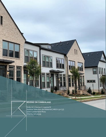
REVERIE ON CUMBERLAND Emily M | Chioma E | Joanna W Systems Selection and Material | ARCH 2311 (3) 4000 Cumberland Pkwy Atlanta, GA 30339
1 I
VOTE OF THANKS We would like to thank the Ashton Woods Company for accomodating us and willingly take us through this learning process. With a project of this magnitude, we appreciate the Project Managers, Mr. Bart and Ms. Ashley. We would also like to thank the school for enabling this experience.
II
INTRODUCTION PROJECT NAME: REVERIE ON CUMBERLAND
LOCATION 4000 CUMBERLAND PKWY, ATLANTA GA 30339
PROJECT OWNER: ASHTON WOODS
PROJECTED FINISH DATE APRIL 2020
Reverie on Cumberland is an upcoming luxurious community 2 miles from SunTrust Park. The community is made up of Townhomes, Lofts and Single- Family Homes and a swimming pool. With 246 units all structures are wood framed most being three story while some are two story homes. With 2020 around the corner, the site is very busy however for this project, focus is on the three story constructions
III
The site is about 67,000 square feet and Ashton Woods designed and are constructing a total of eleven elegant designs for this community and these are floor plans for one of their projects.
Tilson, 3 Bedroom TownHouse
IV
TABLE OF CONTENT
TABLE OF CONTENT TABLE OF CONTENT TABLE OF CONTENT TABLE OF CONTENT TABLE OF CONTENT TABLE TABLE OF OF CONTENT CONTENT Introduction TABLE OF CONTENT I Plans - Site Visit Timeline TABLE OF CONTENT About - Floor Introduction TABLE OF CONTENT
2
6
10
14
36
40 V
Introduction Introduction Foundation Introduction Introduction Introduction Foundation Introduction ExavationFoundation - Footing - Inspection - Concrete Pour Foundation Introduction Introduction Foundation Framing Foundation Foundation Foundation Framing Foundation Framing Foundation Framing DensGlassSystems - Wood Trusses - Platform Framing - Fire Framing Rated Wood Framing Framing Systems Framing Systems Systems Framing Framing Systems Finishes Systems Systems Connections - Plumbing and Electricity - Insulation Systems Finishes Staircase Systems Finishes Systems Finishes Issues on site Finishes Finishes Finishes Issues on site Exterior Finishing Finishes- Load Diagrams - Wall Sections Issues on site Interior Issues on site Finishing Finishes Finishes Issues on site Conclusion Issues Issues on on site site Issues on site Conclusion Issues on site Conclusion Issues on site Conclusion ObservedAppendix Challenges and Outcomes Conclusion Conclusion Conclusion Appendix Conclusion Appendix Appendix Conclusion Conclusion Appendix Appendix Appendix Appendix Appendix Appendix
SITE VISIT TIMELINE SITE VISIT TIMELINE
1 1
10.11.2019
22
10.15.2019
33
10.17.2019
44
10.18.2019
55
10.24.2019
66
10.28.2019
77
10.31.2019
88
11.01.2019
99
11.14.2019 1
FOUNDATION
2
FOUNDATION
The site nee existing tre obstacles t
The site needs to be prepared for contruction by removing any existing trees that are on the site and removing any other obstacles that could affect the contruction process.
The site needs to be prepared for contruction by removing any existing trees that are on the site and removing any other obstacles that could affect the contruction process.
The site needs to be prepared for contruction by removing any existing trees that are on the site and removing any other obstacles that could affect the contruction process.
The land is taken through the exavation process. Soil is removed until reaching the needed depth. In this instance, the land dug has been dug about 8 feet down as shown here. The soil is then flattened and removed of any steepeness the topography of the land might have. All this is done in preparation for the placement of the footings.
8 feet
The land is removed un was dug ab Then the so topogrophy All in prepa
The land is then taken through the excavation process. Soil is removed until reaching the needed depth. In this instance, the land The been land isdug then taken through the process. Soil is on has about 8 feet down asexcavation shown in the two images removed until reaching the needed depth. In this instance, the land the left. The soil is then flattened and removed of any steepness the was dug about 8 feet down as shown in the two images on the left. topogrophy of the land might have. Then soil isin flattened and for removed of any steepness the All thisthe is done preparation the placement of the footings. topogrophy of the land might have. All in preparation for the placement of the footings.
3
The land is then taken through the excavation process. Soil is removed until reaching the needed depth. In this instance, the land
FOUNDATION FOUNDATION
Footings are placed along with reinforcing bars to form the foundational base of each home. The rebars are placed to give the concrete that is to be poured a better structural integrity. Every footing must be placed correctly and after the site pases an inspection done by an engineer, the site is ready for conrete pours.
Footings are placed along with reinforcing bars to form the foundational of each The rebarsbars are placed give Footings arebase placed alonghome. with reinforcing to formtothe the concrete that is to be poured a better structural integrity. foundational base of each home. The rebars are placed to give Every footing must betoplaced correctly and after the site pases an the concrete that is be poured a better structural integrity. Footings are placed along with reinforcing bars to form the inspection done by an engineer, the site is ready for conrete Every footing must be placed correctly. It is here that the pours. foundational base each home. rebarsfor are placed to give site undergoes anofinspection andThe is ready concrete pouring. the concrete that is to be poured a better structural integrity. Moving on to the next step is determined by the engineer Every footing must be placed correctly and after the site pases an during inspection. inspection done by an engineer, the site is ready for conrete pours.
4
FOUNDATION FOUNDATION FOUNDATION
Once the site passes inspections the process begins to move fairly quickly. Concrete is poured into the formwork that was created. Thepasses concrete is mixed offsite and brought to move the Once the site inspections the process begins to construction location.isAbout 7 -into 10 days need to bethat allowed fairly quickly. Concrete poured the formwork was for the concrete to before anyoffsite work and can done begins onthe top to of move it. created. Thethe concrete is mixed brought to Once sitedry passes inspections the be process construction location. Aboutis7 poured - 10 daysinto need be allowed forwas fairly quickly. Concrete thetoformwork that Once the site passes inspections the can process begins the concrete dryconcrete before any work be and done on to topmove of the it. created.toThe is mixed offsite brought to fairly quickly. Concrete is poured into the formwork that was construction location. About 7 - 10 days need to be allowed for created. The concrete is mixed offsite and brought to the the concrete to dry before any work can be done on top of it. construction location. About 7 - 10 days need to be allowed for the concrete to dry before any work can be done on top of it.
5
FRAMING
6
OSB lumber 2x4 stud Screw Sill plate Foam Concrete
DensGlass The DensGlass functions as sheating between the house units. It also functions as a sound-proof material, this is useful because the house units are side by side.
Wood Truss The trusses are tranported to the top of the second floor by a construction vehicle because of its weight. There is no stairway constructed yet, therefore the construction workers have to access the second floor by ladders.
7
DensGlass is placed between all the house units instead of OSB lumber. OSB lumber is placed only on the sides of the house units that do not intersect.
Vertical lumber The vertical lumber is temporal because the cantilever has no structural support to carry its load.
Metal strip
The DensGlass has been cut to custom height and width on site to create space for the diagonal metal strip. The sub-floor is 3/4” thick and is connected by tongue joints.
8
The type of framing done on site is Platfrom framing. It has a number of advantages such as: - use of shorter stud. - it is cost effective. -it reduces the time for fire spread.
Keeping in mind that there are various floor plans used, in this house unit, there is no cantilever which will function as the balcony space.
Fire rated plywood is used for the roof. DensGlass is placed in the middle of the roof. The roof rafters do not overhang in most of the house units because they intersect.
9
DensGlass is placed between all the house units instead of OSB lumber. OSB lumber is placed only on the sides of the house units that do not intersect.
Vertical lumber The vertical lumber is temporal because the cantilever has no structural support to carry its load.
Metal strip
The DensGlass has been cut to custom height and width on site to create space for the diagonal metal strip. The sub-floor is 3/4” thick and is connected by tongue joints.
10
The truss system is a triangulated member of straight interconnected elements. It is good for construction because it helps to remove unnecessary loads. The wood truss is held together by metal plates. To connect the wood truss to other structural members like joist, a metal joist hanger is used at the intersection. A connection is also needed at the point of intersection between the DensGlass and joist. The joist hanger is very simple, in comparison to the complex joist hanger between the truss and joist
Bond nailing The most common type of nailing done on site are toe nailing and bond nailing.
Toe nailing
11
The Theplumbing plumbingsupply supplylines linesare areallallPEX. PEX. ItItisisplaced before the concrete placed before the concrete mixture mixturefor forthe thefoundation foundationisispoured poured into the formwork. into the formwork.
The Theeletrical eletricalwiring wiringsystem systemisis done before the duct done before the ductsystem system and andthe theinsulation insulationisisplaced, placed, because becauseititwould wouldcause causesome some interference. interference. This Thissystem systemconsists consistsofofwires wires and cables that and cables thatconnect connectallall around aroundthe thehouse. house.
The ThePVC PVCduct ductsystem systemisisused usedfor forairair circulation circulationaround aroundthe thehome. home.ItIt distributes distributesheated heatedororcooled cooledairair totodifferent differentparts partsofofthe thehouse. house. There Thereisisa aeletrical eletricalfireplace fireplaceininthe the house, house,which whichmeans meansthat thatseveral several ducts ductsneed needtotobe beconnected connectedtotoit.it.
12
Sheep’s wool is the material used for insulation. Firated foam is used to seal any gap or opening in the framing. It reduces the fire spread in the framing.
Tread
The house has a straight stairway. The stair components are all wood
Nosing Riser Stringer
Blocking Ledger Carriage
13
FINISHING
14
The first part in the process of roofing is fire rated plywood. A roof felt is placed on the plywood as an ice and water shield. The roof shingles are a‘asphalt 3 tab’, which is an architectural dimensional shingle for texture.
Ashton Woods make their own vapor barrier.The vapor barrier protects the OSB lumber from moisture and other weather situations.
The windows are put in before the wood sidings.These are drywall windows composed of a double glaze and vinyl frame. Georgia has energy perfomance rating requirements for windows. The window is a 0.29 solar heat gain coefficient and 0.35 U-factor.
The hardie plank wood sidings are placed on the sheating. The sidings are pressure treated and do not rot. It requires painting every five to six years.
15
The brick facade requires scaffolding to be placed in front of the house.For construction,a Queen size shale brick is used. The dimensions are 23/4” width x 23/4” height x 7 5/8” length. It is also a residential grade brick.
The breaking of brick depends on the mason. The mortar is mixed on site, and the ratio of the mixture varies depending on the weather and color of mortar.
The brick course is Stretcher and the joint is flush. The mortar is placed in the cavities to ensure the brick facade is much more structural. The brick ties are necessary to ensure the structural integrity of the wall. 16
The flat iron ledge is placed around the bottom and top of the window frame, it is also placed at the top of the door frame. The iron ledge is used because of the brich facade, it supports the load.
DETAIL & SYSTEMS
The wo0d sidings are painted after the brick facade has been finished. The paint color solidifies the color pallete.
17
The load of the wood joists and rails are transfered to the wood brackets, transfered to The trusswhich systemare is athen triangulated member of the walls. straight interconnected elements. It is good for construction because it helps to remove unnecessary loads. The wood truss is held together by metal The load of the wood joists and railsthe arewood transfered plates. To connect truss to other to the wood brackets, which are thenlike transfered to joist structural members joist, a metal the walls. hanger is used at the intersection.
A connection is also needed at the point of intersection between the DensGlass and joist. Thefor joist is very simple,toinresist comparison The lumber used thehanger cantiliver is treated to the complex joist hanger between the truss weather actions. It is also customized to acheive and joist the desired design for the railings and such.
The lumber used for the cantiliver is treated to resist weather actions. It is also customized to acheive the desired design for the railings and such.
Bond nailing The most common type of nailing done on site are toe nailing and bond nailing.
Toe nailing
The door overhang is similar to the features of a roof overhang. It does not only perform a decorative funThe door overhang similar to the ction, it protects the isdoor from features of a roof overhang. It does weathering conditions. not only perform a decorative function, it protects the door from weathering conditions.
18
The second floor has a cantilever that is about 8 feet long. Steel beams are used to support the load of the cantilever.
The second floor has a cantilever that is about 8 feet long. Steel beams are used to support the load of the cantilever.
The load of the wood joists are transfered to the steel beams.
The load of the wood joists are transfered to the steel beams.
After most of the exterior finishing is done, the sidewalks are made. The concrete mixture is made on site. To ensure is workable, Afterthat mostthe ofmixture the exterior finishing is a slump is done. The in The the done,test the sidewalks arejoints made. concrete aremixture control/contraction. concrete is made on site. To ensure that the mixture is workable, a slump test is done. The joints in the concrete are control/contraction.
19
4” BRICK PROVIDE LADDER WIRE OR METAL TIE
STUD WALL
1' - 0"
HORIZONTAL REBAR
START HORIZONTAL REBAR SPACING
1' - 0"
0' - 4"
4” THICK CONCRETE SLAB
0' - 10"
WATERPROOF MEMBRANE
2' - 0"
1' - 8"
20” X 10” THICK CONTINUOUS POURED CONCRETE FOOTING WITH (2) REBAR
STEM WALL WITH BRICK SKIRT SCALE: 3/4”=1’-0” 20
WALL HEIGHT =
2' - 0"
7' - 0"
VERTICAL REBAR
WALL SECTION
7/16 Roof Sheathing Uplift Anchor Roof Truss Double Top Plate 1/2 Wall Sheathing 2/4 Stud Wall
3/4 Floor Sheathing Joist/ Truss per plan SECOND LEVEL
Rim Board
FIRST LEVEL
Non- Corrosive Flashing
6x6 P.T. Post
BASEMENT
Treated Sill Simpson Post Base Grade
4” Patio Slab as occurs
TYPICAL EXTERIOR LOAD BEARING WALL SECTIONBASEMENT SCALE: 1/4”=1’-0”
21
Wooden panels are nailed onto the floor to cover framing and to give a flat surface to be able to place final flooring finishes on top of. Wooden panels are nailed onto the floor to cover framing and to give anailed flat surface to befloor able tocover Wooden panels nailed onto the Wooden panels areare onto the floor to to cover place final flooring finishes on top of. framing and to give a flat surface to able framing and toare give a flat surface bebe able to to Wooden panels nailed onto the to floor to place final flooring finishes of. to place final finishes onon toptop of.done cover and toflooring give a flat surface. this is be able to place the final flooring finishes on top of
Wooden floors are placed, however wedges are put inbetween the floor and walls to maintain the two from glueing together and alot space for future baseboard placement and final flooring. Wooden floors are placed, however wedges are put inbetween the floor and walls to maintain theare two Wooden floors placed, however wedges are Wooden floors areare placed, however wedges putput from glueing together and alot space for future inbetween floor and walls maintain two inbetween thethe floor and walls to to maintain thethe two baseboard placement and final flooring. from glueing together and alot space future from glueing together and alot space forfor future baseboard placement and final flooring. baseboard placement and final flooring.
Final flooring has been placed however the next room has not had the final flooring placed therefore a wedge is used to maintain space for the future flooring. Baseboards are placed above and below walls, however they are not yet painted
22
Stairs are given temporary railings while the finishes on them are being added. As with the flooring, Stairs are given temporary railings stairs are composed of wooden while the finishes on them are panels and then primed to later being added. As with the flooring, be given the final wooden flooring. stairs are composed of wooden Stairs are given temporary railings panels and then primed to later while the finishes on them are be given the final wooden flooring. being added. As with the flooring, stairs are composed of wooden panels and then primed to later be given the final wooden flooring.
Final railings are added however the completion of the step flooring has not been finalized
23
The completion of the final finishes in the bathrooms move much faster than other areas in the home. Final light fixtures are placed along with mirrors. This bathroom particularly had a sliding door to reduce the space that a swing dooe would take from a narrow bathroom. Clear doors are placed to enlose the showering area. Toilets are insalted where the drainage tubes are located for the toilets.
24
Appliances in the restrooms such as the sink and cabiinets are added. Flooring is also added, however it is covered along with the sink and the cabinets to protect them from ongoing jobs that are still going on in the bathrooms
Tubs and water resistant wall tiles are placed in the showers and floors are covered to protect them from this process
25
Walls are marked and primed in preparation for painting. The baseboards are specially coated to give a different glossy look from the rest of the walls. Light switches are installed as well
26
The fireplace installations are made, covered with a fire resistant stone material that keeps the fire from catching onto the walls. Some fire places are textured using a marble material
27
Final windows and doors are installed. This is done to be able to work on the exterior masonry however door knobs are yet to be put in place alongside painting of the doors
The door parts - Strike plate, Head, Jamn - are all wooden and connected to the door using a hailed hinge
28
Installations such as plumbing for the sink and exhaust connections are placed in the kithcen
Cabinets are prepped for painting and when ready are painted white. Light fixtures for the kitchen are installed as well as the sink. Appliances and small parts like handles are yet to be placed due to further painting and detailing to be done
29
Final finishes are added to the interior of the home. Wooden flooring is pplaced and walls are primarily painted white. Textured tiles are added on some walls, especially the bathrooms and kitchen. Flooring laminations also differ in some areas of the home depending on the purpose of the area.
In the kitchen, the walls near the sink and the stove are covered with a whitew, octagonal-pattern lamination to give the kitchen a better aesthetic. It is also easier to clean on these laminations and cheaper to replace incase of any damage in the kitchen. The countertop is finished off by sealing it with a dark marble look on the surface
Appliances such as the sinks, ovens stoves and the exhaust hood are placed in the kitchen
30
The ceiling is simply horizontal rods that run across and intersect each other. Light window blinds are placed infront of the windows to give privacy yet still allow light in and maintain view of the back porch The final flooring in the living room iss wood as is the case of most of the home
31
The living room ceiling seems to be trying to represent the structural components of the home by having wooden decorative beams run across the livng room, The light fixture in the livng room mimics the ceiling by simply being hoorizontal rods that run across and intersect each other
Light window blinds are placed infront of the windows to give privacy yet still allow light in and maintain view of the back porch. The final flooring in the living room is wood as is the case in most of the homes.
32
The aesthetics of the home are maintained with the abstract choice of wall decor placed around the interior of the home
Cabinets in the laundry room follow the same dark tone as the Kitchen Cabinets to provide contast to the walls. The flooring pattern enhances the harmony in the color scheme
33
Walls in the room tend not to be flat and are very structural in their design. The structural look is given by the placement of the decorative strips
Windows in the rooms have the same blinds as in the livingroom. Rooms also have several windows, giving lots of light to the rooms and heat from the sun to warm the rooms during winter
Closet Racks are installed and flooring in the closets maintains to be wood
34
Water resistant tiles are placed on the shower walls and final appliances are added such as shower heads and shower curtain roads
The detail in the bathroom appliances such as the light fixtures and the shower heads follow a goledn color scheme. The shower flooring is added and is water resistant. All tiling in the restrooms and showers must be durable and able to resist some loads of water to avoid water from seeping into other areas
35
ISSUES ON SITE
36
Helical Piers TThe main issue we saw on th esite was the site’s ability to pass the The main issue we saw on the site was the site’s ability to pass the inspection of the engineer, This was because the soil in this particular area inspection of the engineer. This was becuase the soil in this particular was to soft to bbuild on. Generally, this is not an issue here in Georgia due area was too soft to build on. Generally this isn’t an issue here in Georgia to strong red clay soil, however on this site, some particular areas had very due to the strong red clay soil, however on this site, some particular soft soil. areas had very soft soil. The footings had to be completely removed along The footings had to be completely removed along with the rebars to be with the rebars to be able to compact the soil and make it strong enough able to compact the soil and make it strong enough to build on. Helical to build on. Helical piers had to be installed due to the unsuitable soil piers had to be installes sue to the unsuitable soil conditions. conditions. Helical Piers The main issue we saw on the site was the site’s ability to pass the inspection of the engineer. This was becuase the soil in this particular area was too soft to build on. Generally this isn’t an issue here in Georgia due to the strong red clay soil, however on this site, some particular areas had very soft soil. The footings had to be completely removed along with the rebars to be able to compact the soil and make it strong enough to build on. Helical piers had to be installed due to the unsuitable soil conditions.
Later a relization came that the area was not dug deep enough and the footings were not exactly placed in their correct locations therefore everything had to be removed in order to dig deeper and correctly place the footings.
37 Later a relization came that the area was not dug deep enough and the footings were not exactly placed in their correct locations therefore everything had to be removed in order to dig deeper and correctly place the footings.
Later a relization came that the area was not dug deep enough and the footings were not exactly placed in their correct locations therefore everything had to be removed in order to dig deeper and correctly place the footings. Later a realization came that the area was not dug deep enough and the footings were not exactly placed in their correct locations. Therefore everything had to be removed in order to dig deeper and correctly place the footings.
the area was not dug deep enough and the footings were not exactly placed in their correct ng had to be removed in order to dig deeper and correctly place the footings.
While working on masonry, the windows need to be installed before hand because the masonry will ultimately leave an opening to be able to see through the windows. This exposes the windows to falling bricks and possibly getting need smashed When doing masonry, the windows to be by one asbefore was the case in the photographs installed hand becuase the masonry on will the left. This wastes of to windows ultimately only leave materials an opening be ableand to see requires the replacement theexposes broken the window(s) through windows.of This windows to falling bricks and possibly getting smashed by one as was the case in the fotos to the left. This wastes materials of windows and requires someone to replace the broken window.
38
When doing masonry, the windows need to be installed before hand becuase the masonry will ultimately only leave an opening to be able to see through the windows. This exposes the windows to falling bricks and possibly getting smashed by one as was the case in the fotos to the left. This wastes materials of windows and requires someone to replace the broken window.
Weather is also a large inhibitor of production at contruction sites, especially rainy weather. Rain stops almost every exterior finishes and does not allow siting activities. In some instances if weather gets too cold, it shuts down masonry work. Brick cannot be installed under 32 degrees farenheit. To be able to install masonry, the weather must be 35 degrees farenheit or higher. Unsuitable weather can also affect the duration and the wellness of concrete cures. Unsuitable weather slows down all different forms of production at construction sites
Weather is also a large inhibitor of production at contruction sites, especially rainy weather. Rain stops almost every exterior finishes and does not allow siting activities. In some instances if weather gets too cold, it shuts down masonry work. Brick cannot be installed under 32 degrees farenheit. To be able to install masonry, the weather must be 35 degrees farenheit or higher. Unsuitable weather can also affect the duration and the wellness of concrete cures. Unsuitable weather slows down all different forms of production at construction sites
When framing, sometimes a roof truss breaks when delivering them to the top of the structure.In such instances an engineer comes up with a repair letter and this could add more materials to the roof truss bringing in other considerations as to where the loads are now going and how strong the truss system is.
When framing, sometimes a roof truss breaks when delivering them to the top of the structure.In such instances an engineer comes up with a repair letter and this could add more materials to the roof truss bringing in other considerations as to where the loads are now going and how strong the truss system is. 39
APPENDIX
40
1. EXAVATION 2. GROUNDWORK 3. FOUNDATION 4. WOOD FRAMING 5. INSULATION 6. SYSTEMS 7. EXTERIOR FINISHING 8. INTERIOR FINISHING
41
42
Exavation_1
Exavation_2
Exavation_3
Exavation_4
Exavation_5
Exavation_6
Exavation_7
Exavation_8
Exavation_9
Exavation_10
Groundwork_1
Groundwork_2
Groundwork_3
Groundwork_4
Groundwork_5
Groundwork_6
Groundwork_7
Groundwork_8
Groundwork_9
Groundwork_10
Foundation_1
Foundation_2
Foundation_3
Foundation_4
Foundation_5
Foundation_6
Foundation_7
Foundation_8
Foundation_9
Foundation_10
Wood Framing_1
Wood Framing_2
Wood Framing_3
Wood Framing_4
Wood Framing_5
Wood Framing_6
Wood Framing_7
Wood Framing_8
Wood Framing_9
Wood Framing_10
43
44
Insulation_1
Insulation_2
Insulation_3
Insulation_4
Insulation_5
Insulation_6
Insulation_7
Insulation_8
Insulation_9
Insulation_10
Systems_1
Systems_2
Systems_3
Systems_4
Systems_5
Systems_6
Systems_7
Systems_8
Systems_9
Systems_10
Exterior Finishing_1
Exterior Finishing_2
Exterior Finishing_3
Exterior Finishing_4
Exterior Finishing_5
Exterior Finishing_6
Exterior Finishing_7
Exterior Finishing_8
Exterior Finishing_9
Exterior Finishing_10
Interior Finishing_1
Interior Finishing_2
Interior Finishing_3
Interior Finishing_4
Interior Finishing_5
Interior Finishing_6
Interior Finishing_7
Interior Finishing_8
Interior Finishing_9
Interior Finishing_10
45
THE END
46
47