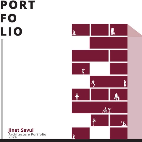
POR T FO LI O
J inet Sa vul
Architecture P or t fol i o 2024
C
O
N
T
Indoor Public Corridor
Outdoor Public Corridor
01 1
3D View 2
CLOUD ON THE HILL
03
02
03
04
FUSION CENTRAL
URBAN WALK-UP HOUSING
NARKOMFIN HOUSING
13
19
25 1
REINFORCED CONCRETE (VARIABLE)
WATERPROOFING
SATIN PLASTER (2cm)
REINFORCED CONCRETE
PLASTIC PAINT 7,5 13,2 5 4
NATURAL STONE THERMAL INSULATION WATERPROOFING
25
REINFORCED CONCRETE
E
N
T
538
370
T
ARTIFICIAL STONE 3cm MORTAR 3cm LEVELING CONCRETE 4cm REINFORCED CONCRETE 20cm ROUGH PLASTER 2cm 90
SATIN PLASTER PLASTIC PAINT
22
PLASTIC PAINT SATIN PLASTER
Ø45 mm PAINTED ALUMINIUM HANDRAIL
ROUGH PLASTER 1,5cm REINFORCED CONCRETE WALL 30cm
20
ARTIFICIAL STONE STEP
19 18 17 16
90
15 14 13 38,75 38,65
1110
20
11
370
6
12
339
10 9 8 7 6 30
ARTIFICIAL STONE 3cm
5
MORTAR 3cm LEVELING CONCRETE 4cm
4 90
ROUGH PLASTER 2cm SATIN PLASTER
2
PLASTIC PAINT
SATIN PLASTER ROUGH PLASTER 1,5cm
1
22
REINFORCED CONCRETE WALL 30cm Ø45 mm PAINTED ALUMINIUM HANDRAIL
33,90 33,80
16,8
16,8
PLASTIC PAINT
344
REINFORCED CONCRETE 20cm
3 16,8
30
21 20
ARTIFICIAL STONE STEP
19 18 17
ARTIFICIAL STONE 3cm MORTAR 3cm
16
REINFORCED CONCRETE 20cm
15
SATIN PLASTER
90
ROUGH PLASTER 2cm
14
PLASTIC PAINT
B2051 FIRE STAIR
13 12
6
35,05 34,95
370
20
11
339
10 9 8 7 202
30
6
176
5
ARTIFICIAL STONE 3cm MORTAR 2cm
4 90
LEVELING CONCRETE 5cm REINFORCED CONCRETE 10cm
3
GRAVEL FILL 40cm REINFORCED CONCRETE 50cm
2 1 30,20 30,10
40
10
10
16,8
16,8
16,8
30
06
07
08
09
WATCHTOWER
EAA STAIR DETAILS
3D WORKS
COLLAGE & ASSEMBLAGE
29 2
33
37
41
01
Cloud On The Hill Positioned in the heart of Madrid, the complex, strategically placed across from COAM, deftly weaves nine diverse programs—three Educational Spaces, three Sports facilities, and three miscellaneous functions—within the constraints of a small site defined by narrow streets and low residential buildings. Tailored to fit the urban context, each program is thoughtfully designed in varying sizes—Small, Medium, and Large—ensuring a seamless integration with the surrounding environment. Amidst the challenges posed by spatial limitations, the Educational Spaces provide unique learning experiences, the Sports facilities cater to diverse athletic pursuits, and the miscellaneous functions contribute to the overall vibrancy. In the bustling heart of Madrid, my design introduces a transformative architectural concept that redefines the interaction between the city’s ground plane and its citizens. At its zenith, a ‘cloud’—a versatile theater space—floats, offering a beacon of culture and community engagement against the urban skyline.
This project is not merely an architectural endeavor but a vibrant, multipurpose venue designed to host a myriad of events, enriching Madrid’s cultural landscape. The structure’s essence lies in its ability to engage with users on multiple levels, creating a series of unique spatial experiences as one moves through it. Central to the design is the creation of open spaces within the urban density, providing much-needed respite and communal areas in the city’s core. These spaces serve as urban retreats, where the dynamism of city life meets the tranquility of open, accessible areas. My design philosophy embraces the complex relationship between form, functionality, and the urban fabric, ensuring that each interaction within the structure is distinctive. This project aspires to be more than just a building; it seeks to become a landmark that embodies the spirit of Madrid, offering new perspectives and experiences to all who engage with it.
3
4
Horizantal Circulation Vertical Circulation Diagonal Circulation
Concept Diagram
Circulation Diagram
Site Plan
Program Diagram
Elevation
5
6
Site Analysis
7
“Cloud Level”
8 Level 2
Level 1
Ground Level
Basement Level
EXHIBITION
RESTAURANTS
C E N T E R CREATIVITY
F A B L A B
C E N T E R 9
ENTERENCE
G
TV
RECORDING
K
R
O
PLAYGROUND
10
O
M
Y I
M D
S
Model experimenting with the night view
Materiality Reference Project: OMA Serpentine Gallery Pavilion
Cloud from 14 ping pong balls
11
Cloud from water baloons
12
02
FUSION CENTRAL This urban design studio embarked on a transformative project in the neighborhoods of Mission Hill and Roxbury, Boston. The endeavor began with a comprehensive analysis that included mapping, photographic documentation, and historical study, uncovering the layers of change shaped by policy, expansion, and community action. It became evident that the evolution of these areas had impacted their diverse communities unevenly, setting the stage for our forward-looking urban design interventions. In this project I collaborated with 2 other architecture students to develop a framework that proposes integrated solutions for building design, program distribution, and the creation of dynamic public spaces. Central to this vision is the enhancement of community gathering spaces, accessibility, and local economic vitality.
the local economy through support for retail. Ensuring universal accessibility is a cornerstone of the project, aiming to create an inclusive environment for all residents. Access to healthy food options stands as a priority, promoting well-being within the neighborhoods. The project aims to be a testament to the power of collaborative urban design, combining architecture, landscape architecture, and planning, to craft a holistic vision. This initiative strives not only to reimagine the physical space but to foster a resilient community spirit in Mission Hill and Roxbury, enriching the lives of residents for decades to come.
Our design proposals focus on fostering open spaces for community engagement, improving multi-modal transportation for seamless accessibility, and bolstering 13
14 1
3D View 2
Illustrative Axonometric
9'-0" Sidewalk
4'-0" Plating Zone
10'-0" Travel Lane
10'-0" Travel Lane
6'-0" Bike Lane
4'-0" 8'-0" Plating Sidewalk Zone
15
Design Framework Diagram
9'-0" 4'-0" Sidewalk Plating Zone
16
10'-0" Travel Lane
10'-0" Travel Lane
6'-0" 4'-0" 8'-0" Bike Plating Sidewalk Lane Zone
Landscape Driven Building Forms
RE
Shap thou shar
URBAN EDGE Activate the urban edge by designing ground-floor spaces,contribute to the public realm by providing well-designed sidewalks and pedestrian zones enriched with street furniture, greenery, and amenities to foster a welcoming environment for residents and passersby.
BUILDING ENTERENCE BUFFER ZONE In the buffer zone, incorporate low planters or fencing to define the patio space, fostering privacy, while adhering to a maximum height of 4 feet to maintain a visual balance that preserves street views.
PEDESTRIAN ZONE Provide a sidewalk with a width of 4 to 5 feet to accommodate pedestrians, ensuring a safe and comfortable pathway for walking within the designed space.
Offset the building entrance by 2 feet to create a distinct and visually emphasized entry point, facilitating resident orientation and effectively distinguishing individual unit entrances from the primary building entrance.
GROUND FLOOR OFFSET All ground floor units must have a minimum setback of 4 feet from the main building facade to allow for the creation of private patios.
FRONTAGE ZONE Ensure a 6-foot frontage zone is integrated into the private patio design, providing residents with a designated area for personalization.
PLANTING ZONE
BIKE LANE
Incorporate a 3 to 4-foot planting zone as a boundary between the sidewalk and the bike lane, ensuring a well-defined separation, and plant trees with a minimum spacing of 20 feet between them to enhance the aesthetic and functional aspects of the urban environment.
Establish a one-way bike lane with a recommended dimension ranging from 5 to 6 feet.
CURB ZONE Integrate a 2-foot curb between the bike lane and the transportation lane to enhance safety by clearly delineating the spaces, mitigating potential conflicts, and ensuring a secure environment for both cyclists and other forms of transportation.
PUBLIC (Urban Edge)
TRANSPORTATION LANE Allocate a 10-foot lane for cars to facilitate smooth and safe vehicular movement, ensuring proper traffic flow and accommodating standard vehicle dimensions within the designed transportation infrastructure.
17
ESIDENTIAL APARTMENT
pe residential apartment structures in an "L" configuration to ughtfully integrate with existing buildings, fostering the creation of a red open space withing the block.
OPEN SPACE EDGE Incorporate green buffers and diverse landscaping to seamlessly transition between the built environment and open space, enhancing visual appeal, and ensure well-defined, accessible pathways along the open space edge to facilitate easy connectivity for residents, considering pedestrian flow and universal design principles.
OPEN SPACE Common open space with oppertunities of community gathering.
Design Guidelines Transections
This residential project’s design guidelines integrate private and public realms within an urban context, prioritizing accessibility and pedestrian engagement. The entrance and urban edge are inviting and interactive, blending seamlessly into open, green spaces that extend peaceful views to residents. Functional ground offsets incorporate nature at the doorstep, enhancing livability. Transportation solutions, including dedicated bike lanes, ensure safety and promote eco-friendly travel. Pedestrian zones are accentuated with ample lighting and greenery, facilitating a pleasant and environmentally sound atmosphere. Public seating and interconnected pathways encourage community connectivity and social interaction, while open communal areas offer recreational opportunities, creating a vibrant and cohesive urban living environment. GROUND FLOOR UNIT ENTERENCE Create a 3-foot pathway connected to the urban pathway, facilitating direct access to the ground floor unit entrances, ensuring a well-defined and accessible route for residents to reach their homes from the common urban pathway.
BUILDING ENTERENCE Establish a 6-foot pathway seamlessly connected to the urban pathway, leading directly to the building entrance, ensuring a clear and accessible route for residents to navigate towards the entrance with ease.
FRONTAGE ZONE Incorporate a 6 to 8-foot frontage zone within the patio design, providing residents with an ample and personalized space, enhancing the overall livability and aesthetic appeal of the outdoor area.
BUFFER ZONE Include a 1 to 1.5-foot buffer zone between the open space and the patio to establish clear boundaries, allowing for decorative elements such as plants, with a height restriction not exceeding 3 feet to maintain an aesthetically pleasing transition while ensuring an open and inviting atmosphere.
PRIVATE (Open Space Edge) PUBLIC SEATING Integrate benches into the buffer zone to serve as public seating, enhancing the open space's usability and providing a welcoming environment for residents and visitors to enjoy the surrounding area.
URBAN PATHWAY
OPEN SPACE
18
Leverage the open space created by enclosed buildings to incorporate diverse programs, such as recreational activities, cultural events, and interactive installations, with the aim of engaging and attracting visitors, fostering a vibrant community atmosphere, and enhancing the overall appeal of the site.
Ensure the 12-foot urban pathway is designed to accommodate both pedestrians and cyclists, adhering to ADA accessibility standards, thereby promoting inclusive mobility and creating a versatile space for residents to walk or ride within the enclosed environment surrounded by buildings.
03
WALK UP HOUSING In this project my focus is to the design housing intended to function as a prototype for site-specific urban interventions. A central emphasis is be placed on walk-up units, prioritizing wood-frame buildings without elevators as a relatively unexplored, low-cost, and high-density alternative in urban residential development. The project recognizes the potential social benefits of diverging from the conventional elevator-and-corridor circulation model. Particularly noteworthy is the versatility of organization afforded by walk-up wood-frame buildings, allowing for a wider array of circulation solutions compared to traditional double-loaded corridor structures. I aimed to explore innovative avenues in housing design with a keen eye on cost efficiency, density, and social considerations.
surrounding context. Plans are developed both as single modules and aggregations of three building modules, with a focus on housing Northeastern University graduate students and allocating 13% for the City of Boston’s affordable housing program. Unit designs for upper floors aligns with a social agenda, contemplating bedroom proximity, layout efficiency, and spatial variety, while also providing private open spaces. The final step was designing ground floor accessible units and their private open spaces, modeling the prototype, refining facades, and designing open spaces, emphasizing front and rear gardens, pedestrian alleys, and optional elements like deciduous trees.
In this multifaceted design process, the first step involved selecting a circulation approach for a four-floor prototype, either with a single stair or a single corridor on the third floor. The subsequent phase required generating alternative plans adhering to design guidelines and considering the relationship to the 19
Interior POV
Exterior POV 20
Level 1 Floor Plan
Level 2 Floor Plan
Ground Floor Site Plan
Level 3 Floor Plan
Level 4 Floor Plan
Section Perspective
21
Axonometric View
22
23
24
04
NARKOMFIN HOUSING In analyzing a housing precedent, I focused on comprehensively understanding its circulation armature, organizational concept, and the spatial/experiential outcomes of these organizational strategies. This involved generating analytical diagrams to elucidate the key features. The analysis specifically delves into critical plans and sections, providing insights into the scale of the building and highlighting the nuances of its spatial and experiential aspects. The ultimate goal is to gain a profound understanding of the organizational principles that shape the housing precedent, facilitating both comprehension and effective presentation to the designated section. The Narkofmin Housing, constructed during the Constructivist movement in Russia under the USSR, represented a paradigm shift from individual family housing to collective communal living. Embracing avant-garde architecture, the design aimed to foster a socialist lifestyle by encouraging residents to engage in communal spaces rather than confining themselves to individual households. The apartments featured a
to individual households. The apartments featured a vertical separation, allocating bedrooms on the upper floors and communal living spaces on the lower, with minimal kitchen space to encourage the use of shared facilities. The complex comprised two distinct living spaces, “Type K” for families with larger living areas, and “Type F” for smaller groups embracing communal living with compact cooking and dining spaces. Designed for workers at the Russian Ministry of Finance, the building adopted a single orientation with a single-loaded corridor every third floor to optimize natural light. Elevated on piers, the ground and top floors were dedicated to communal living, while intermediate floors housed long corridors and two-level apartments. A connecting bridge facilitated public access, featuring kitchens, a dining hall, and a library. Beyond architectural innovation, the project aimed to influence inhabitants’ habits and manners, promoting collective and communal behaviors to reshape social norms.
25
Pedestrian / Vehicular Access
Cross Section Through Residential Block 26
Project Imgery
Public Common Area Vertucal Circulation Main Access Cooridoor Open to the outside
Main Access Corridor open to the outside Vertical Circulation
Program Diagram
Public Common Area
27
Floors 3-5 Includes apartment unit type F spanning three floors access by another interior cooridoor.
Ground Floor Plan
First Floor Plan
Second Floor Plan
Second Floor Type K Upper Level
Second Floor Type K Upper Level
Type F
Site Plan Private 63%
Indoor Public Corridor
54
Total Units
Other 25%
Second Floor Type K Lower Level
Circulation 12% Project Distribution
Second Floor Type K Upper Level
Ground Floor
10
54
% Open Space
Units per Acre
Penthouse
16
1T ype F
16 16
2T ype K
Type F
3T ype K
Unit Distribution
4,05
1.7
Average % Outdoor Corridor Unit Area Public Net-to-Gross
42,000
18,185
2.5
Parcel Area Total SF
Building Area Total GSF
Typical Floor Total GSF
Floor Area Ratio
Project Data Summary
28
6
42,000
Ground Floor
Indoor Public Cooridor
Outdoor Public Coordior
Type K
Typical Units
07
WATCHTOWER This project focuses on exploring the expressive potential of wood light frame construction through the design of a two-level ‘watchtower.’ The location is intentionally non-specific and flat, allowing the structure to highlight the characteristics of wood frame construction, such as lightweight standardized elements, modular planning, simple assembly, and diverse formal possibilities. The configuration requirements aim to showcase the “load path,” emphasizing how loads follow a specific path to reach the ground. Notably, heavy timber materials are prohibited, limiting the use of ‘2x’ members, with none exceeding a length of 16 feet. This project encourages a deep exploration of wood construction principles and their potential for architectural expression.
level, must have a minimum floor area of 100sf and 80sf of rough openings for windows. The upper level must be supported by stairway walls, with cantilevered space beyond the lower level’s footprint. The roof, featuring cantilevers, must demonstrate proper support and drainage at one or two points. Preliminary submissions require schematic design drawings, including first and second floor plans, roof plans, a section, and elevations. The final project involves constructing a 1/2” = 1’-0” scale basswood model, accurately representing wood framing pieces without using a laser cutter.
The foundation includes a 4’ deep crawl space with a 2’ wide by 1’ deep footing and a 10” thick poured-in-place concrete foundation wall. The lower level is limited to a stair, an entry door, and landings, with specific dimensions for treads and risers. The upper level, situated at least 9 feet above the lower 29
2
3
First Floor Plan
4
1
Second Floor Plan
Roof Plan 30
31
32
07
EAA STAIR DETAILS 270
Ø45 mm PAINTED ALUMINIUM HANDRAIL
ARTIFICIAL STONE 3cm MORTAR 3cm REINFORCED CONCRETE 20cm
PLASTIC PAINT
ROUGH PLASTER 2cm 90
SATIN PLASTER ROUGH PLASTER 1,5cm REINFORCED CONCRETE WALL 30cm
SATIN PLASTER PLASTIC PAINT
125
Ø45 mm PAINTED ALUMINIUM HANDRAIL 38,75 38,65
ARTIFICIAL STONE STEP
90
During the summer of 2023, I had the opportunity to intern at Emre Arolat Architecture in Istanbul, Turkey, working under the guidance of a renowned Turkish architect, Emre Arolat. My primary responsibility was to create detailed stair drawings for a prestigious project known as Nef Gölköy, located in what is often referred to as the paradise bay of Bodrum. This luxury development was set to feature 89 independent villas with private pools, 42 of which boasted unique designs, spread across a 46,000 square meter site. The villas varied in size from 400 to 1200 square meters. Being part of a project team dedicated to this development, I was meticulously guided through the stair design process by my group leader, ensuring the accuracy of my work. Given that the project was already under construction, the importance of precision in my drawings was paramount to avoid delays, emphasizing the need for minimal errors due to the time-sensitive nature of the work.
125
33
2
1
GRAVEL 4cm PROTECTIVE CONCRETE 5cm GEOTEXTILE MAT POLYSTRENE HEAT INSULATION TILE 13cm ELASTOMER BITUMINOUS POLYESTER WATER PROOF (2 x 3mm) 10 5
20
5 5
BITUMINOUS PRIMER
5 5
WATERPROOFING
WATERPROOFING
REINFORCED CONCRETE
PLASTIC PAINT
538
370
25
7,5 13,2 5 4
THERMAL INSULATION REINFORCED CONCRETE
ARTIFICIAL STONE 3cm MORTAR 3cm LEVELING CONCRETE 4cm REINFORCED CONCRETE 20cm ROUGH PLASTER 2cm 90
SATIN PLASTER PLASTIC PAINT
22
PLASTIC PAINT SATIN PLASTER
Ø45 mm PAINTED ALUMINIUM HANDRAIL
ROUGH PLASTER 1,5cm REINFORCED CONCRETE WALL 30cm
20
ARTIFICIAL STONE STEP
19 18 17 16
90
15 14 13 38,75 38,65
1110
20
370
6
12 11
339
10 9 8 7 6 30
ARTIFICIAL STONE 3cm
5
MORTAR 3cm LEVELING CONCRETE 4cm
4 90
ROUGH PLASTER 2cm SATIN PLASTER
2
PLASTIC PAINT
SATIN PLASTER ROUGH PLASTER 1,5cm
1
22
REINFORCED CONCRETE WALL 30cm Ø45 mm PAINTED ALUMINIUM HANDRAIL
33,90 33,80
16,8
16,8
PLASTIC PAINT
344
REINFORCED CONCRETE 20cm
3 16,8
30
21 20
ARTIFICIAL STONE STEP
19 18 17
ARTIFICIAL STONE 3cm MORTAR 3cm
16
REINFORCED CONCRETE 20cm
15 90
ROUGH PLASTER 2cm SATIN PLASTER
14
PLASTIC PAINT
B2051 FIRE STAIR
13 12
6
35,05 34,95
370
20
11
339
10 9 8 7
176
202
30
6 5
ARTIFICIAL STONE 3cm MORTAR 2cm
4 90
LEVELING CONCRETE 5cm GRAVEL FILL 40cm REINFORCED CONCRETE 50cm
2 1 16,8
16,8 10 10 40
34
REINFORCED CONCRETE 10cm
3 16,8
30
30,20 30,10
5 10
THERMAL INSULATION
REINFORCED CONCRETE (VARIABLE)
NATURAL STONE
20
NATURAL STONE
SLOPED SCREED (VARIABLE 5-8cm) SATIN PLASTER (2cm)
2
1
1
A
5
A
45
60
22x(30/16.82)
03
120
45
125
30
60
03
30
60 125
60
120
35,05? ±0,00 34,95
22x(30/16.82)
45
REINFORCED CONCRETE 25cm ROUGH PLASTER 1,5cm SATIN PLASTER PLASTIC PAINT
30
REINFORCED CONCRETE 25cm ROUGH PLASTER 1,5cm SATIN PLASTER PLASTIC PAINT
*NATURAL STONE
2
270 30
20 15
Ø40 mm PAINTED ALUMINIUM HANDRAIL
*ARTIFICIAL STONE STEP
8
330
7
14
9
15
8
16
7
17
6
Ø40 mm PAINTED ALUMINIUM HANDRAIL
625
6
10
330
30
30
30
13
11
02
10
9
12
30
12
01 11
30
*ARTIFICIAL STONE STEP
20
3
21
125
2
1
*ARTIFICIAL STONE STEP
*ARTIFICIAL STONE STEP
*ARTIFICIAL STONE STEP
30
30,20? ±0,00 30,10 60
60
60
45
FIRE 17
30
30
170
M01 FIRE STAIR 17,9 m² 164
30
30
45
4
22
30
*ARTIFICIAL STONE STEP
1
19
ANTI SLIPPERY SANDING
170
2
*ARTIFICIAL STONE STEP
30
3
5
30
125
4
18
30
5
30
ANTI SLIPPERY SANDING
60
20
45
+ 30,10 LEVEL FLOOR PLAN
35
2
2
1
REINFORCED CONCRETE 25cm ROUGH PLASTER 1,5cm SATIN PLASTER PLASTIC PAINT 45 60
30
03
*NATURAL STONE
20 15
30
20 15
*ARTIFICIAL STONE STEP
8
16
7
30
14 *ARTIFICIAL STONE STEP
15
16
6
17
625
17
13 Ø40 mm PAINTED ALUMINIUM HANDRAIL
30
15
B
9
330
30
10
14
12
02
13
02
30
11
30
30
01 30
01
30
45
30
*NATURAL STONE
60
30
270
30
155
22x(30/16.82)
3
35,05? ±0,00 34,95 60
30
45
120
30
60
125
60
38,55 ±0,00 38,65
30
5
A
4
3
*ARTIFICIAL STONE STEP
2
*ARTIFICIAL STONE STEP
1
20
21 22
170 60
30 30 30
20
45
+ 33,80 LEVEL FLOOR PLAN
36
45
60
60
60
45 20
60
30
30
30
165
200
M01 FIRE STAIR 17,9 m² 165
30
270
30
30
37,60 ±0,00 37,50
200
M01 E STAIR 7,9 m²
19
30
*ARTIFICIAL STONE STEP
22 33,90 ±0,00 33,80
125
30
20
21
18
125
30
19
5
30
18 125
ANTI SLIPPERY SANDING
+ 37,50 LEVEL FLOOR PLAN
08
3D WORKS
Gyroid
Tools: Rhin Printer
37
d
Dissolving Cup
no, Grasshopper, 3D Material: Wire
38
Evolving Skins, Sculpting Light
Throughout this project, I embarked on a journey that melde tools such as ChatGPT, GHPython, and Grasshopper to delve into fascination with gyroid structures introduced me to the challenges to my fledgling familiarity with the necessary software. This challeng equally captivating realm of Voronoi patterns. The shift was facilitated as crucial guides, filling the gaps left by my attempts to collaborate wi and 3D printing of a cube adorned with Voronoi patterns, realized a thoughts on the practical application of such designs, from decorati was not just a test of my problem-solving capabilities but also a pro preciation for the synergy between parametric design and architectu
39
ed creativity with technical exploration, utilizing the intricacies of parametric design. My initial s of materializing complex designs, largely due ge nudged me toward the more accessible yet d by an array of tutorial videos, which emerged ith AI. My endeavor culminated in the modeling across various scales. This exploration spurred ive lamps to architectural facades. This project ofound learning experience, deepening my apural aesthetics from a first-person perspective.
40
09
COLLAGE & ASSEMBLAGE
London Sky, 2023 mix media This collage showcases the vibrancy of London through a triptych of city scenes under bold, colored skies. The left panel contrasts historical architecture with a serene green sky, the middle pulses with the city’s hustle beneath a royal red, and the right offers a peaceful residential street under a calm blue. This piece captures the essence of London’s dynamism and architectural charm.
41
Andalucia Patterns, 2023 mix media “Andalucía Patterns” is a collage inspired by my recent journey through Andalucía, where the intricate patterns, architectural structures, and lush vegetation of the city left a profound imprint. This artwork captures the essence of Andalucían symmetry and proportions, weaving together the visual rhythms and textures encountered, to create a piece that embodies the vibrant spirit and cultural tapestry of the region.
42
Little Windows on Narrow Streets, 2023 mix media, collage on paper A captivating collage that draws its inspiration from the enchanting cityscape of Madrid. This artwork meticulously encapsulates the unique charm and mystique of the city’s narrow windows, each framing a distinct narrative yet collectively exuding a harmonious beauty. Elements of mystery and coziness, portraying Madrid’s streets as a tapestry of intimate tales and aesthetic allure. Turkish Thanksgiving, 2023 mix media As a Turk, Thanksgiving is not a holiday I grew up celebrating. However, this collage represents the food I grew up eating and how I imagine Thanksgiving would look like when I host a Thanksgiving dinner in 2070.
43
Urban Patchwork, 2023 mix media, collage on paper A surrealistic perspective of urban life, where the vibrancy of Madrid’s architecture is celebrated in a gravity-defying display. In this elevated nook, the intimacy of indoor life—complete with cozy furnishings and the warmth of domesticity—is starkly framed against the sprawling cityscape. It’s a creative exploration of private and public realms. 44