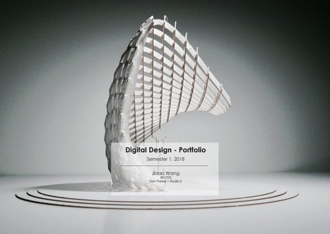
Digital Design - Portfolio Semester 1, 2018 Jiaao Wang
881703 Dan Parker + Studio 6
1
email: jiaaow@student.unimelb.edu.au
Content:
03
Design Precedent Study: Burnham Pavilion
05
Generating Design Through Digital Processes
Education:
Reflection:
2017 - current Bachelor of Design, University of Melbourne, Major in Architecture 2015 - 2017 Bachelor of Engineering, South China Agricultural University, Major in Civil Engineering
In Module 1, when I did some researches for Burnham Pvilion, a video interested me a lot. Two dancing people can be obviously seen in the evening because the light from pavilion lit them up. On the contrary, the pedestrians are not easy to be seen because they are not be lit up. So there is a invisible threshold between public and private area being defined by light, instead of physical threshold like doors or windows. That inspired me and was used in my design in Module 3.
Work Experience: 2018 Group
16
Site Worker, Zhongtian Construction
Queen Victoria Garden Pavilion: Light Island Awards / Exhibition: 2017
MSDx: Design Studio Alpha Exhibition
Lots of skills I learn during this course. For digital design, I
2017
FOD: R Exhibition, AFLK Gallery
can use grasshopper to help me to create many parametric designs. I can use Unreal Engine to render my model. In terms of fabrication, I can use lazer cutting for waffle making. Anohter exciting skill is I know how to fabricate through 3D printing, which is awesome.
Skills: Rhino Grasshopper Unreal
I enjoy the experience when I was brainstorming to find my ideas to design in Module 3. As a designer, my aspiration is to design something that can suprise myself. If I was not excited by a idea, I would not stop to explore more.
Photoshop Illustrator Indesign Fabrication
Because many ideas that I had were exciting me a lot but I can not model them in Rhino, the area I need improvement should be digital design tools. I may explore more skills, preparing for more difficult design
2
ideas.
Diagramming Design Precedent
When I studied Burnham Pavilion as a precedent for threshold, I found another kind of threshold that was not simply a physical door or seat. This kind of threshold is created by light. When it is dark around Burnham Pavilion, the pavilion itself becomes a huge light source. The area that is lit on will be a public area, on the contrary, the dark area will be a more pravate space naturally. This idea inspired me a lot in Module 3.
Isometric of your precedent study
3
Circulation Diagram
Threshold Diagram
4
Generating Ideas Through Process
5
Design Matrix
Lofts
1.1
1.2
1.3
Key
1.4
{0,0,0} {-143,129,143}
{-30,105,150 }
{-90,45,1 50}
{-129,143,143}
{57,143,143}
{0,143,143}
{-143,0,143}
{71,143,143}
{143,143,114}
{135,0,1 5}
{-135,90, 0}
{-75,150,0}
Grid Points
{143,0,143} {15,150,15} {100,143,0}
{0,0,0}
{93,13,150}
{96,28,150}
{-35,143,0}
{0,0,0}
{-143,43, 0}
{-12,17,105}
{112,117,0}
{0,0,0}
{15,15,0} {129,0,0}
{86,-30,0} {143,0,0}
{0,0,0}
Paneling Grid & Attractor Point
{Index Selection}
{Index Selection}
{Index Selection}
{Index Selection}
2.1
2.2
2.3
2.4
{58,-6,144}
{-25,159,12}
{122,23,149}
{143,0,143} {0,0,127}
{100,143,0} {134,118,6} {14,0,31}
Paneling
{Attractor Point Location}
{Attractor Point Location}
{Attractor Point Location}
{Index Selection}
3.1
3.2
3.3
3.4
+
6
Attractor / Control Po
Attractor / Control Cu
{-11,108,105}
Surface and Waffle
The panels on this side have solid and sharp sense that is what I want to create contrast to the other surface. Each single panel is made of two extruded cones. One cone (Series A) is pointing up sharply. The other one (Series B) is much more plane. The cones in Series A become sharper and sharper from bottom to top, from front to back, which is controled by two attractive points. However, the volumes of the cones in Series B become smaller form front to back, which is controled through adjusting the points on these panels.
This side’s panels show a sense of dissolution. All panels seem like totally plane and solid but actually there is a very narrow gap in each single panel to let the inner light come out slightly. The light will light up the panel, creating a sense of penetration. Also, the gaps in two panels, that neighbour directly with each other, face different directions to create varietion.
The waffle is created by two very twisted surfaces so it shows that each piece of this waffle structure is rotating and scaling. This idea inspired me when I was designing the shape of my pavilion in Module 3. Similarly, the waffle structure in my pavilion has the sense of rotating and scaling.
Because I wanted these two surface to be as twisted as they can, I manipulated them by controling their end points. The model I made shows that the ‘rotating and scaling effect’ is already reached but one lesson I learned is that I should consider the difficulty of fabricating this kind of twisted model.
7
Computation Workflow
Surface: Choose eight points that
Panelling: Use paneling tools
Waffle Making: Create a waffle
Extract the Edges of waffle: Extract
are on the edges of a box. Line them up and create two surfaces.
to create panels on two based surfaces
structure based on two surfaces I choosed.
the edges of the waffle structure and arrange them in a specific order.
8
9
Insert photos of assembly process or other detail related to your fabrication process
For knowing fabrication tools better, I used two cutting tools in this module. One is lazer cutting and the other is card cutting. Lazer cutting is more presice and neat, which is a better choice. Although card cutting is free and usually I don’t need to queue for it, but it is not neat enough so it is better to use when emergency.
10
11
SOLID AND VOID
This model could be seen as a pavilion with several opennings and a corridor. In the top drawing, the arrow indicates the entrance to the corridor that is getting more and more narrow, which is leading people to explore interal space. There are three open frames at the left side. They could be some waffle seats for people who want to sit and have a rest. At the right side, it is totally open to outside. There could be a public space for gallery or eating space.
In terms of geometry, because I used mathematics to control the scale of all the geometries, so the space and hollow section have a flow from bigger to smaller. And it is interested to find out that the hollow spaces in different surfaces are various.
12
Design Matrix
Grid Manipulation
1.1
1.2
1.3
Key
1.4
{0,0,0}
{21,0,-150}
Attractor / Control Poin
Attractor / Control Curv
{156,0,186}
Grid Points {124,150,150}
{-28,146,-29}
{132,0,74}
{13,144,71}
{110,30,-20} {78,143,-29}
{150,150,0}
Geometries Distribution
{Curve Attraction}
{Curve Attraction}
{Curve Attraction}
{Curve Attraction}
2.1
2.2
2.3
2.4
{51,88,33} {78,143,-29}
{51,88,33}
Geometries Transformtion
{Point Attraction}
{Curve Attraction}
{Random Attraction}
{IDirection Attraction}
3.1
3.2
3.3
3.4
{Rotate All Geometries by Grasshopper}
{Use Mathematic Way to Enlarge the Scale’s Variation}
{-150,100,0}
{Input Geometry (Octahedron)}
{Attractive Point Changes Geometries’ Scale}
13
Computational Process
Point Grid: divide a plane by 4*4
Cell Grid: Use several points and
Place Geometries: place geometries
point grid. Then move this point grid to create three more point grids.
lines to attract and manipulate these grid points. Create cell grid by there manipulated point grids.
through matching thier center point to these point grids. Use mathematic expressioin to scale these geometries.
14
M2 Task 2 3D Printing
Photo of physical model.
When the model I want to 3D print has hollow holes, I need to rotate the model to an appropriate angle, which can reduce the amount of supporting materials. After I did that, the fee and time will reduce too.
15
The light effect of the physical model when it is very dark.
LIGHT ISLAND
The concept of my pavilion is aiming to create a light pavilion. Through this pavilion I want to achieve a effect called ‘LIGHT THRESHOLD’. The space in this pavilion is totally enough for a seminar during lunchtime and it can provide shade for the people inside. In the evening, the pavilion would be a large light source. Accompanied with the platform, the pavilion could be a stage for quarter’s performance. The platform and pavilion would be lit up to be a public space, where everyone nearby could see. On the contrary, audience can stand at the dark area, around the platform, where could be a private space. The pavilion would be reinforced to the timber platform by bolting them together. There will be support material in timber platform to bear the load from the people on it. And there will have foundation to support the platform and pavilion on the ground. Because I want sunlight to lit up the interior space for lunchtime seminar. More importantly, the pavilion will be a light source in the evening so the material should let the light penetrate from inside to outside. So the material of the panels on my pavilion should be semi-transparent. They may be made of glass or plastic.
16
Isometric
17
Design Iteration
First Version: I wanted to create a organic relationship between roof and seats through using grasshopper. Where roof is going down, the seat will sink down to be the ground. The area of the ground depends on how far the roof goes down.
Second Version: Start to rethick about my idea in Module 2. Continue to develop the rotating and scaling effect.
18
Final Version: Continue to develop the idea. Slightly change the skeleton of my pavilion for having a sense of flowing and waving.
19
20
21
Computational Process
Basic Skeleton: Use grasshopper to
Waffle Making: Create waffle
Populate lights on platform: Use curve
3D Panels: Use attracting points to
build up this skeleton. This is inspired by my rotating and scaling waffle strucutre in Module 2.
surfaces based on the skeleton. use grasshopper to create notches on these surfaces.
and point attractor tools to populate the lights on platform. To reach the effect that the pavilion is absorbing these lights, leading people to go inside.
scale the paneling grid in order to let the 3D panels become smaller and smaller from front to back.
22
Fabrication process
I used two fabrication tool to make my physical model. One is lazer cutting. I used it to cut my waffle structure. The waffle is very precise and neat, which is the advantage of lazer cutting. But it is too labour-intensive. I spent about four hours to assemble these waffle pieses. The other tool is 3D print. It is labour-saving and efficient but the surfaces of the product are not very smooth and neat.
23
360 Image Output
Digital Design Semester 1, 2018 24