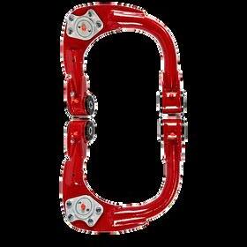
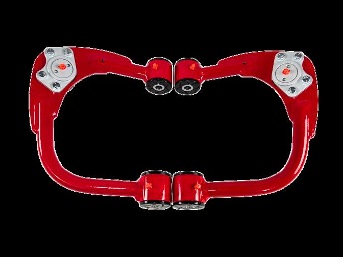
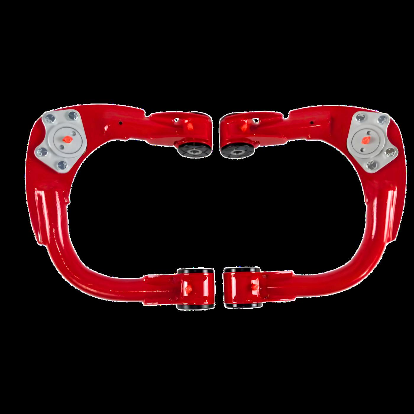
Toyota Tacoma 2005-2023
Toyota 4Runner 2003-2024
Toyota FJ Cruiser 2007-2014
Lexus GX470 2003-2009
Lexus GX460 2010-2023
Toyota Hilux/Vigo 2005-2015
PLEASE
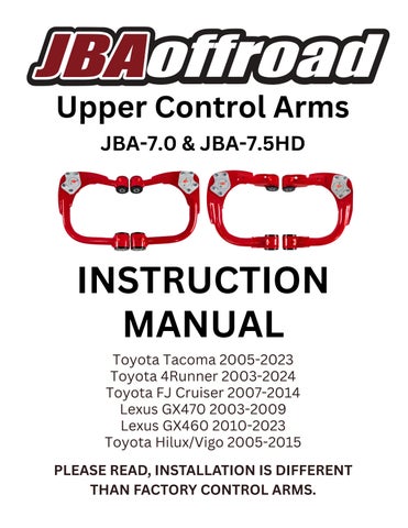
Toyota Tacoma 2005-2023
Toyota 4Runner 2003-2024
Toyota FJ Cruiser 2007-2014
Lexus GX470 2003-2009
Lexus GX460 2010-2023
Toyota Hilux/Vigo 2005-2015
PLEASE
DO NOT ADD BALL JOINT SPACERS OR MODIFY THE BALL JOINT MOUNTS. ADDING SPACERS CREATES ADDITIONAL LEVERAGE AND STRESS ON THE UPPER CONTROL ARM, WHICH CAN CAUSE BENDING, CRACKING, OR SUDDEN STRUCTURAL FAILURE. THIS CAN RESULT IN LOSS OF VEHICLE CONTROL, SERIOUS INJURY, OR DEATH.
JBA UPPER CONTROL ARMS ARE ENGINEERED FOR SPECIFIC GEOMETRY WITHOUT SPACERS OR MODIFICATIONS. SUCH MISUSE VOIDS ALL WARRANTIES AND IS DONE ENTIRELY AT THE USER’S OWN RISK. JBA ASSUMES NO LIABILITY FOR ANY DAMAGES, INJURIES, OR LOSSES RESULTING FROM MODIFICATIONS OR MISUSE.
GENERAL WARNINGS: NEVER WORK UNDER AN UNSUPPORTED VEHICLE. ALWAYS USE JACK STANDS RATED FOR YOUR VEHICLE'S WEIGHT.
JBA UPPER CONTROL ARMS SHOULD BE INSTALLED BY A QUALIFIED TECHNICIAN OR EXPERIENCED INSTALLER. A PROFESSIONAL FRONT-END ALIGNMENT IS REQUIRED AFTER INSTALLATION.
RE-CHECK ALL MOUNTING HARDWARE TORQUE SPECIFICATIONS AFTER THE FIRST 100–300 MILES.
GREASE BALL JOINTS AND BUSHINGS WITH LITHIUM MOLY FORTIFIED EP GREASE BEFORE FIRST USE AND EVERY 3,000–5,000 MILES THEREAFTER.
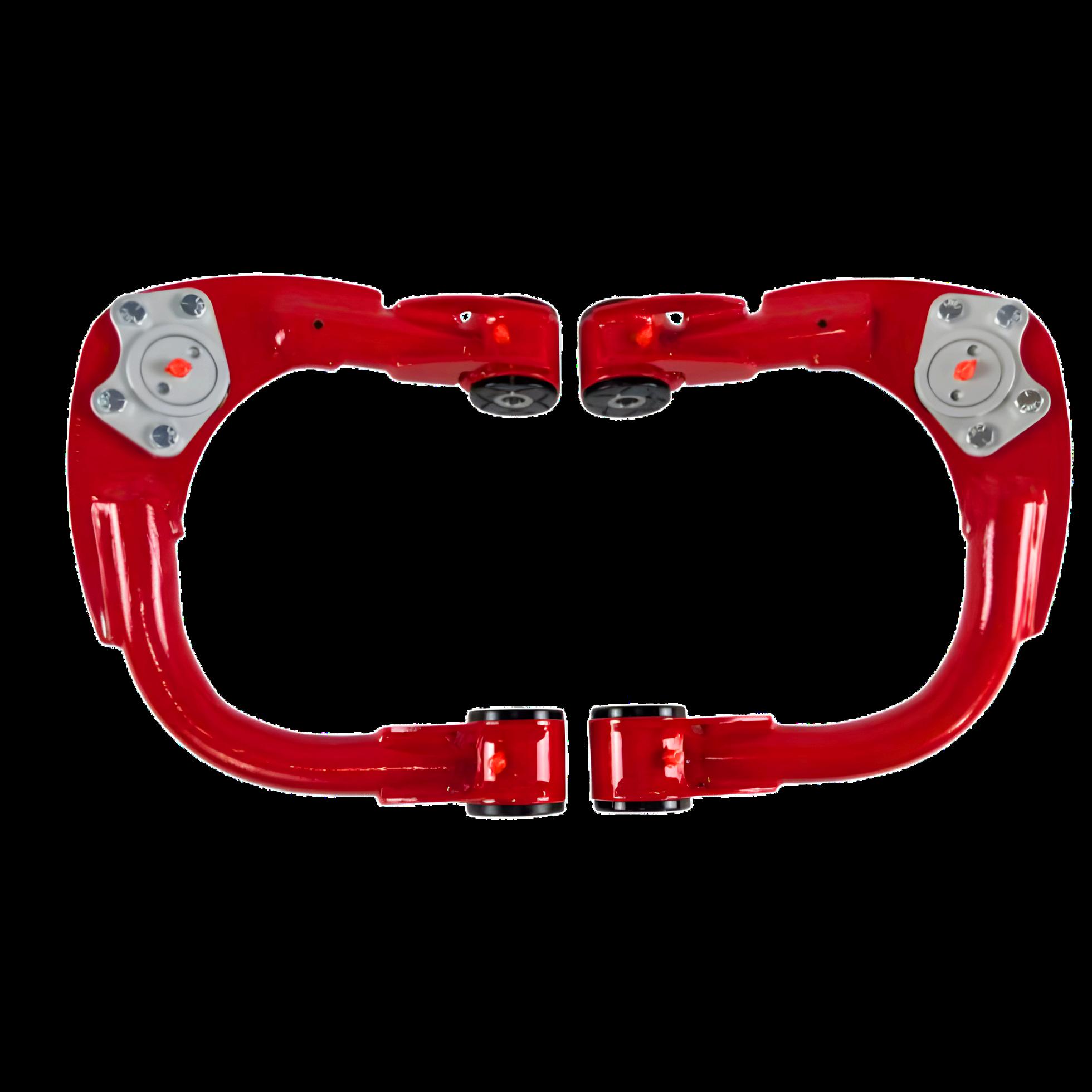
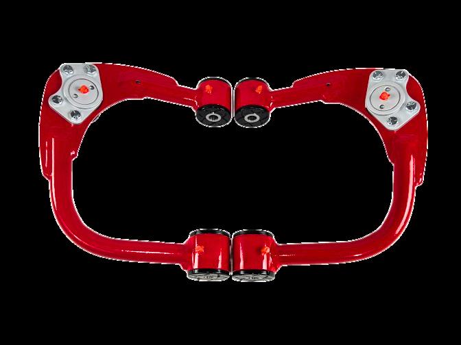
JBA upper control arms are engineered for specific vehicle applications. Use outside intended specifications voids warranty coverage. Warranty determinations are made at JBA’s discretion. JBA Offroad components should be installed by a qualified technician or experienced installer.
JBA has a lifetime warranty on the structural integrity of our upper control arms.
JBA has a one-year warranty on ball joints, bushings, and powder coating.
Adding ball joint spacers to the JBA upper control arms. Adding spacers creates additional leverage and stress on the upper control arm, which can cause bending, cracking, or sudden structural failure. Adding bump stops that hit the JBA upper control arms.
Adding limiting straps attached to the JBA upper control arms. Cutting, grinding, welding, or modifying the JBA upper control arms.
Using the JBA arms on a vehicle, and/or a lift kit they were not designed for.
JBA upper control arms are not designed to be used when stacking two lift kits together.
Taking part in any of these practices voids all warranties and constitutes misuse for which JBA bears no responsibility or liability.
To submit a claim, please provide:
Proof of purchase (including order ID).
Description of the issue.
Scan to begin your claim.
Clear photos of the affected component.
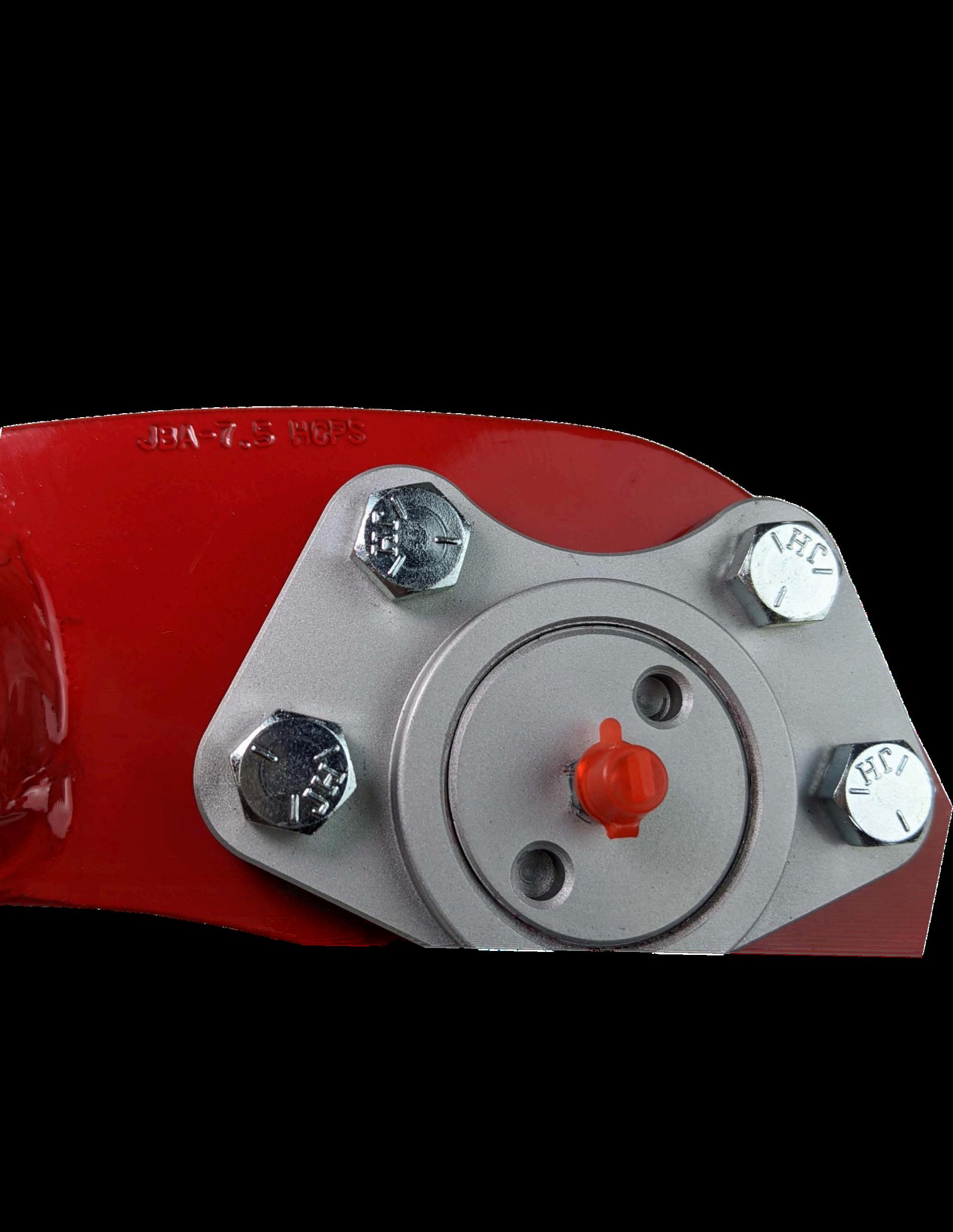
BEFORE INSTALLATION, CONFIRM THE FOLLOWING:
Part number matches your order.
High Caster or Stock geometry version.
Driver or Passenger side (USA driven vehicles).
Matching left and right arms.
If anything is incorrect, contact us before installation and we will
Do not disassemble your vehicle until your parts have been verified.
REAL PEOPLE. REAL BUILDS. REAL RESULTS.
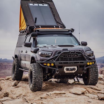
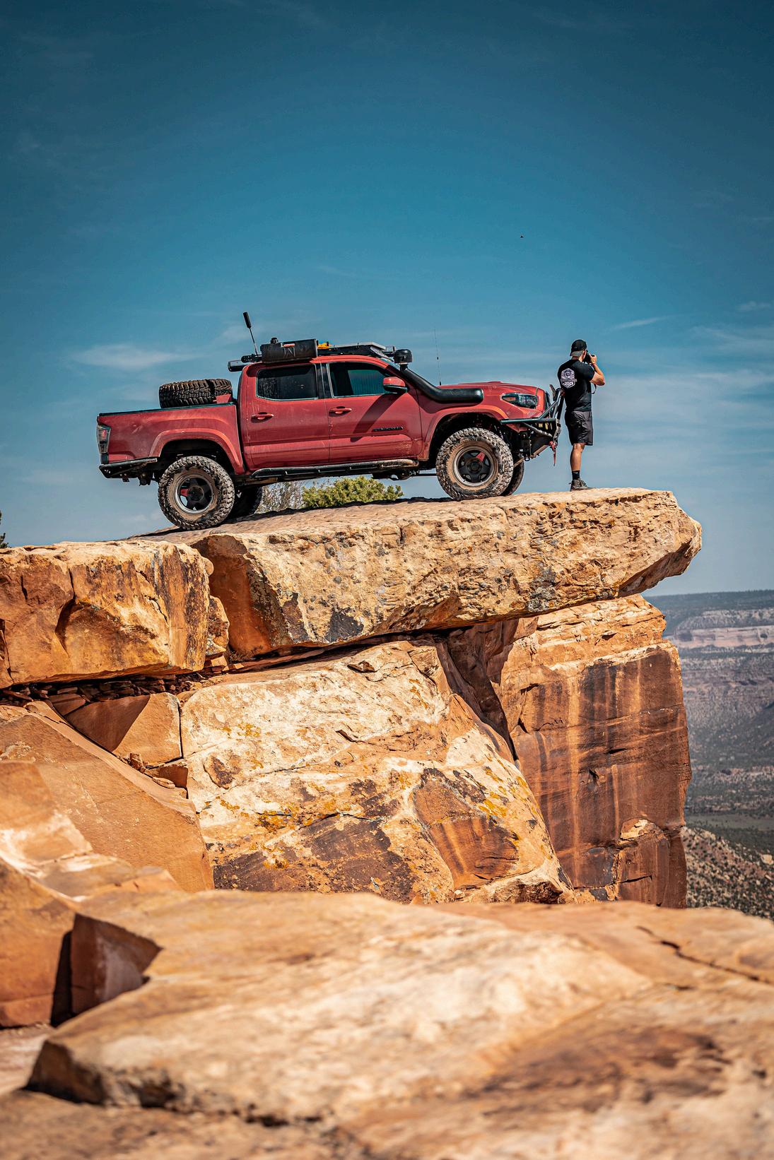
Explore our database of customer builds using JBA Upper Control Arms. Filter by vehicle, lift height, tire size, and more.
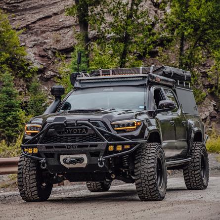
Owner: @Panahrama
2016 Toyota Tacoma
Tire Size: 315/70/r17
Wheel Offset: -38
Lift Height: 3"
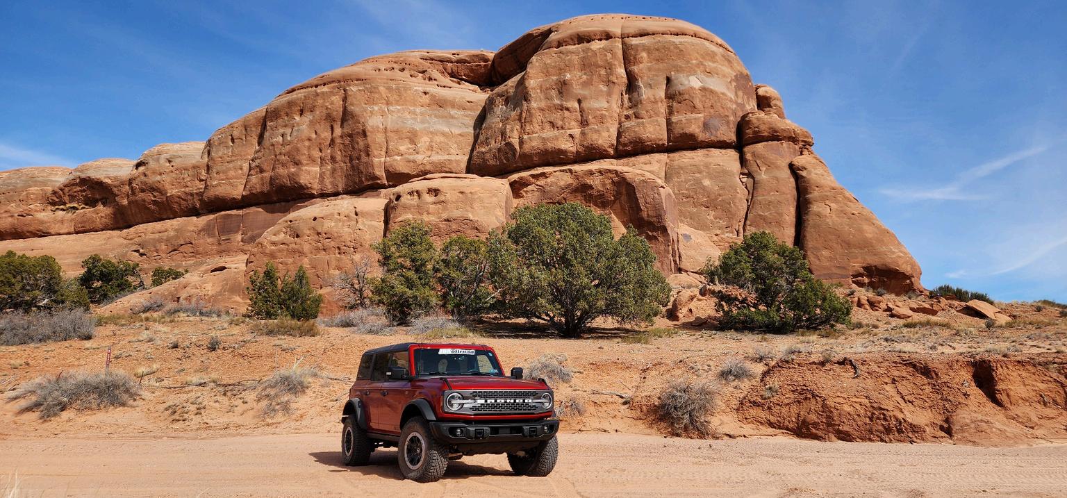
Control Arm: HD High Caster
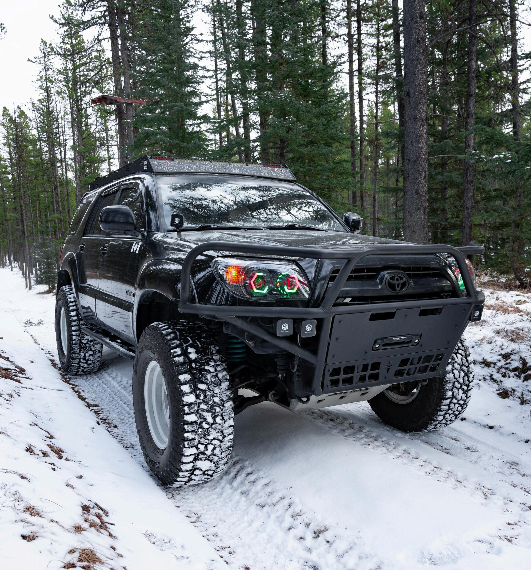
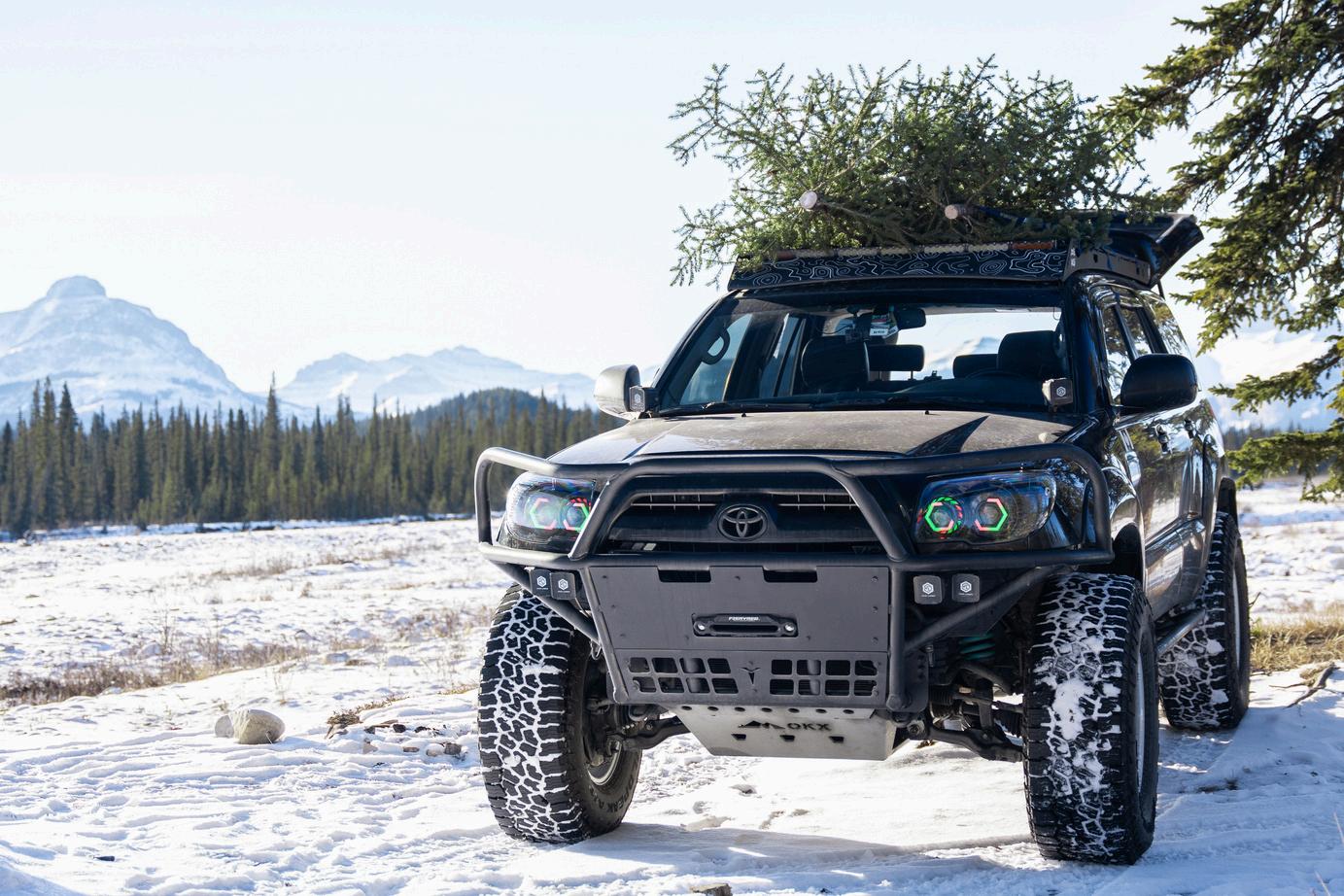
Owner: @LooseAxles
2007 Toyota 4Runner
Tire Size: 35x12 5 R17
Wheel Offset: -38
Lift Height: 3.5"
Control Arm: HD High Caster
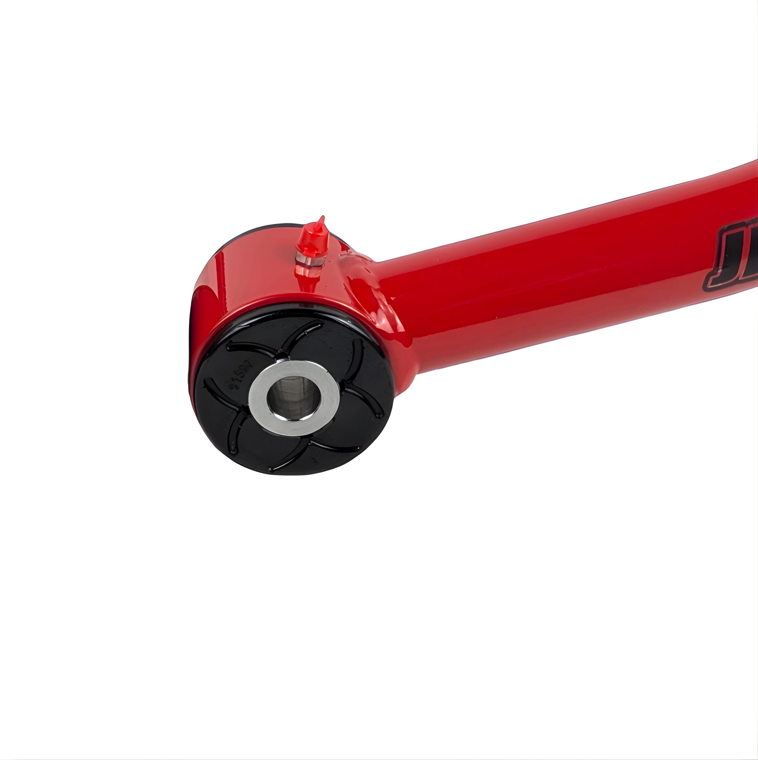
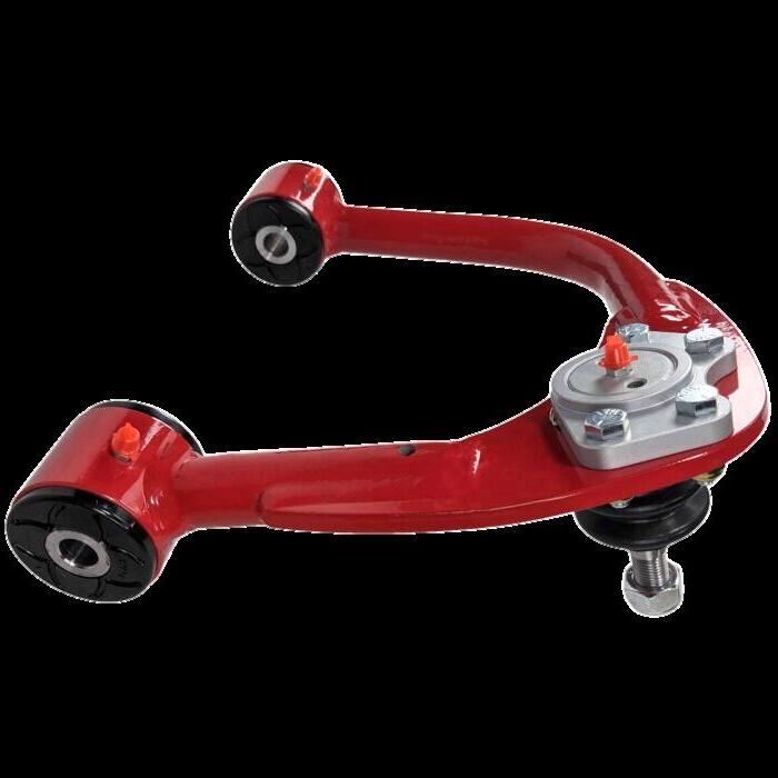
JBA EZ Lube Bushings are patented, fully serviceable bushings designed for durability and quiet performance.
One way relief valves seal out dirt and water. Advanced synthetic elastomer construction.
Internal lubrication channels for full surface greasing.
Serviceable without loosening control arm mounting bolts.
EZ Lube Bushings are used in all JBA Upper Control Arms.
To Service Bushings:
Do not loosen mounting bolts during greasing.
Attach grease gun to bushing fitting.
11,953,070
12,247,631
Pump lithium moly fortified EP grease until fresh grease appears between washers.
Wipe away excess grease.
Service Interval:
Grease every 3,000 to 5,000 miles.
After deep mud, water crossings, or heavy off-road use.
Inspect For:
Squeaking, binding, and excess movement.
Damaged fittings.
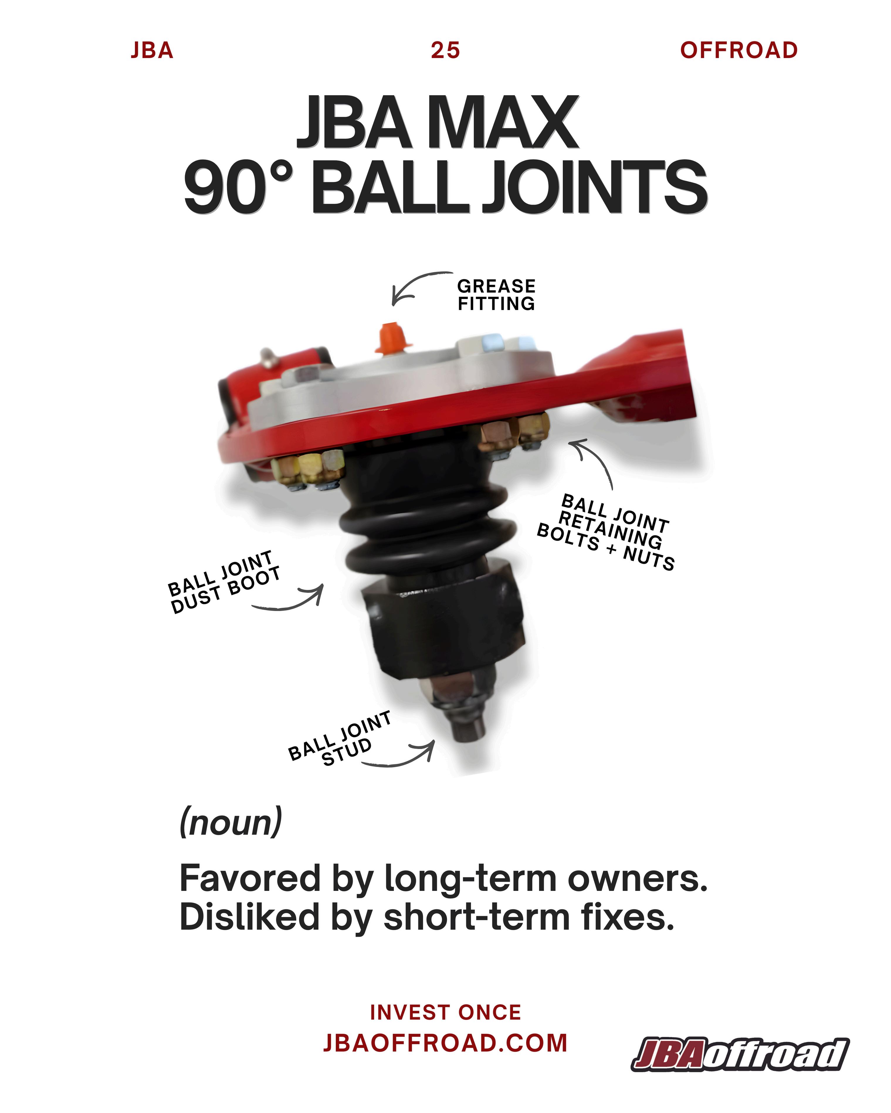
JBA joints are fully serviceable and designed for long term durability.
Heavy duty construction for off-r
Replaceable internal components
Greaseable design for extended lif
Serviceable without replacing the en control arm.
90 degrees of articulation.
WARNING: DO NOT ADD BALL JOINT S MODIFY THE BALL JOINT MOUNT. DOI
RESULT IN LOSS OF VEHICLE CONTRO INJURY, OR DEATH.
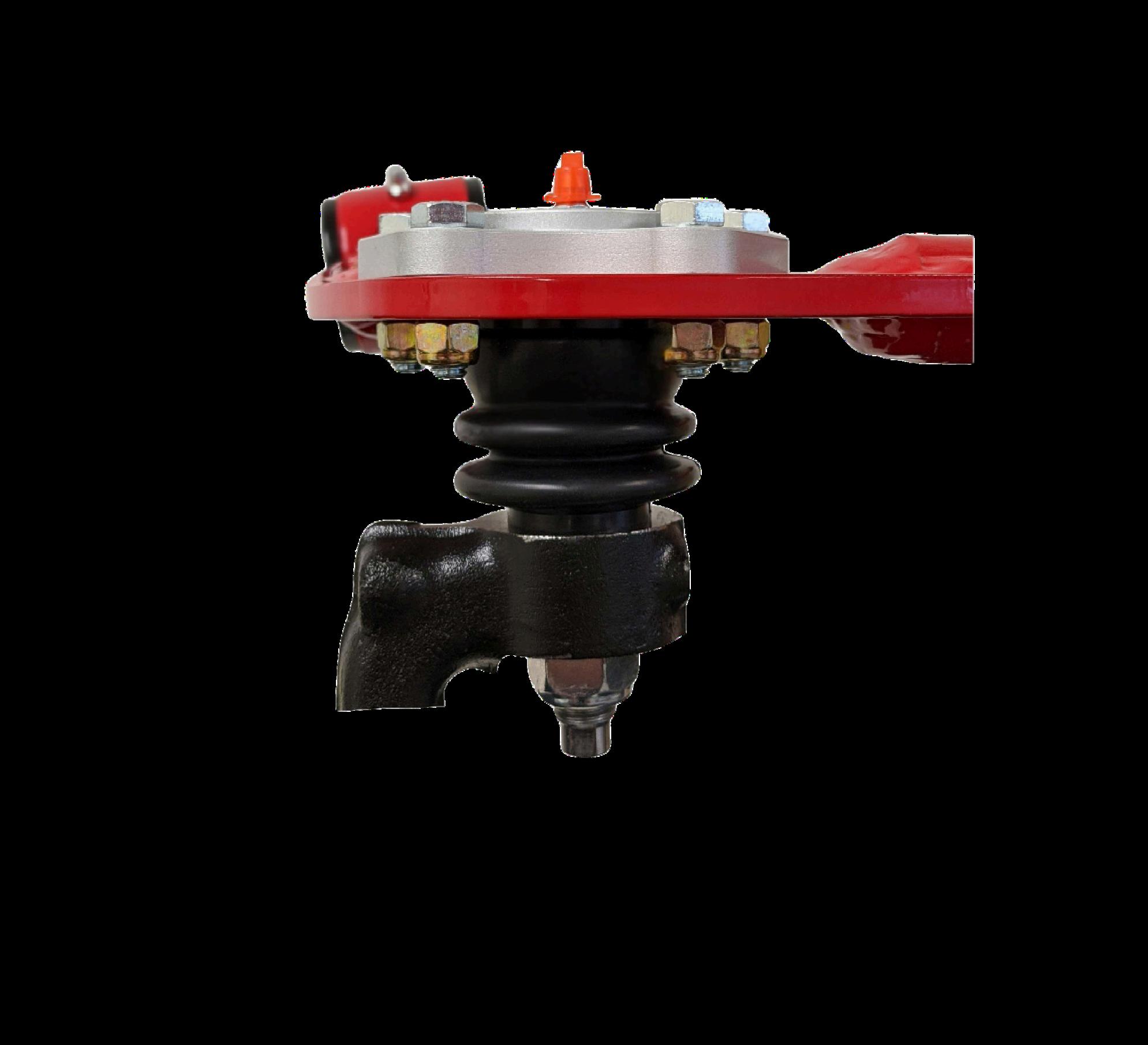
For long lasting ball joints, ensure you:
Add 3 to 5 pumps of lithium moly fortified EP grease until the boot slightly expands. Old grease may vent out of the boot.
Clean the grease fitting before and after servicing.
Service every 3,000 to 5,000 miles or after mud, water, or heavy off-road use.
Inspect for:
Boot cracks or tears. loose or damaged fittings.
Excess play or noise. Contamination.
How to Check JBA Ball Joints: Scan to learn more!
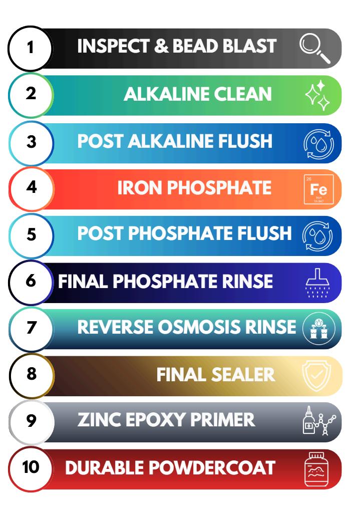
JBA steel upper control arms undergo a 10-stage industrial powder coating process.
Each step prepares the steel, prevents corrosion, and ensures maximum coating adhesion for long term durability.
This multi stage system protects against rust, chipping, peeling, and premature coating failure.
Every JBA upper control arm undergoes a final visual inspection to verify coating consistency, full coverage, and finish quality before leaving our facility.
The upper control arms are finished with Tiger Drylac Bengal Red powder coating and oven cured at 400°F to achieve a fully cured, durable, and long-lasting finish.
Minor chips or shop accidents can happen. We offer factory matched touch up paint. Scan the code for ordering details.
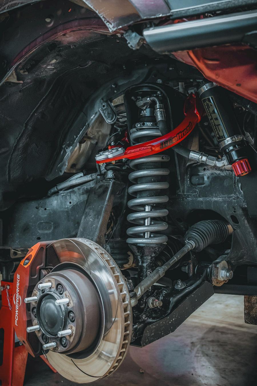
1.Prior to installation, verify the part number matches your order. Confirm Driver and Passenger side arms are correctly identified and oriented prior to removal (stamped near the ball joint).
2.Raise the vehicle and support it securely with jack stands placed under the frame rail behind the front wheel. Remove the wheel. Never work under an unsupported vehicle.
3.Loosen the nut from the ball joint stud and separate the ball joint from the steering knuckle. If striking the steering knuckle beside the stud does not loosen the press fit, a puller tool may be required.
4.Use a jack stand to support the loose spindle. Make sure the brake lines are not being stretched and remove the ABS wire from the top of the UCA.
5.Remove splash guards from wheel well and remove the nut/washer on the end of the long shear bolt. (You may have to unbolt the brake line bracket from the frame).
6.Start removing the shear bolt. On the passenger side, the AC line may block the bolt from sliding out. If needed, unclip the AC line from its holder and remove the bolt securing the AC line bracket so the line can move slightly out of the way. This will allow the shear bolt to slide out completely. Do not remove the nuts on the AC line, as this will release refrigerant. The driver’s side is not obstructed, so the shear bolt can be removed normally. You may need to gently bend the inner wheel well sheet metal to allow the shear bolt to slide past.
Installation Procedure
1.Apply a light coat of grease to the outer surface of the EZ Lube bushings prior to installation.
2.Position the UCA in place and insert the long shear bolt from the front of the vehicle toward the rear. You may need to install one side of the arm first, then angle the thin washer on the opposite side to guide the bushing into position.
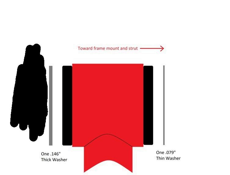
Shear bolt head → 0.156" thick washer → black bushing → red bushing sleeve → black bushing → 0.074" thin washer → UCA tube mounted to chassis → 0.074" thin washer → black bushing → red bushing sleeve → black bushing → 0.156" thick washer → nut. Apply thread locker (Loctite) to the bolt and nut threads.
3.If needed, unbolt the brake hard line bracket and move the line slightly out of the way to allow a torque wrench to fit. Torque the shear bolt nut to 85 ft-lbs.
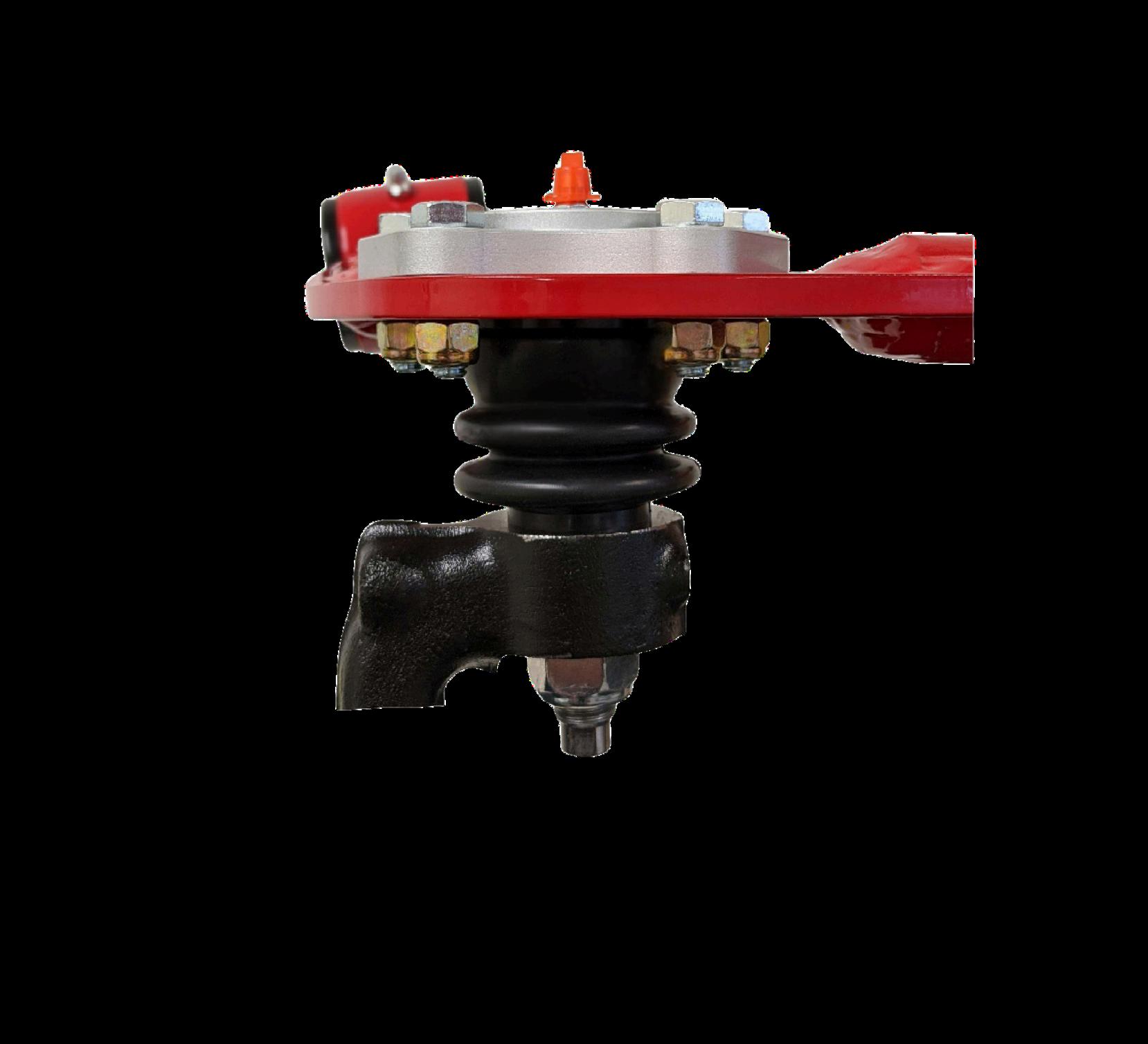
4.Insert the ball joint stud into the spindle. Install the nut finger tight, then torque to 60 ft-lbs. If the stud spins, use a 3/8" hex wrench to hold it while tightening.
5.Torque the ball joint retaining nuts to 13 ft-lbs.
6.Reattach the ABS wire to the top of the UCA and reattach the brake line bracket to the frame.
Installation continued on next page.
Installation Procedure Continued
7.Reinstall splash guards and clips.
8.Reinstall the wheel and torque lug nuts in a star pattern. Lower the vehicle from the jack stands.
9.Grease the ball joint with 3–5 pumps of lithium moly fortified EP grease until the ball joint boot just begins to swell.
10.Grease the bushings with lithium moly fortified EP grease until fresh grease is visibly pushing out from the EZ Lube ports.
11.Repeat the procedure on the opposite side.
12.Re-check all mounting hardware torque specifications after the first 100–300 miles.
Scan to view the full installation video. The video follows the same steps outlined in this manual.
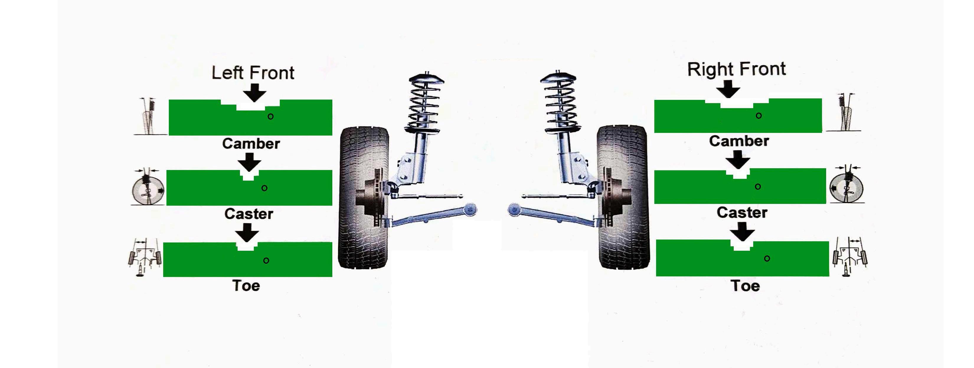
Camber is the inward or outward tilt of the tire when viewed from the front of the vehicle. Too much negative or positive camber can cause uneven tire wear.
Caster is the forward or rearward tilt of the steering axis when viewed from the side. More positive caster improves straight-line stability and steering wheel return to center.
Toe is the direction the tires point relative to each other when viewed from above. Incorrect toe is the fastest way to destroy tires.
Lifting an independent front suspension reduces positive caster, which can cause light steering and reduced highway stability. JBA upper control arms restore lost caster to improve tracking, steering return, and overall stability.
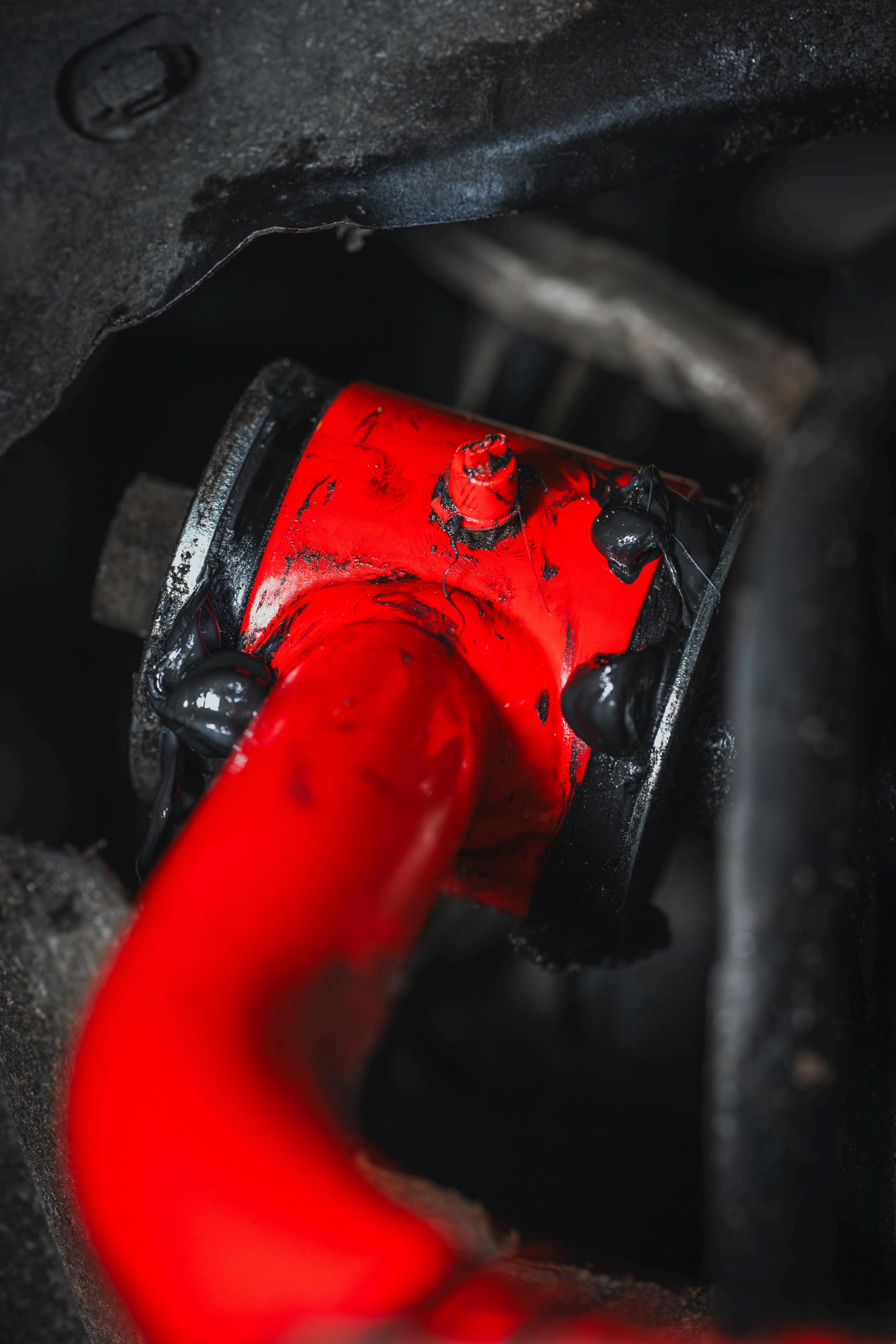
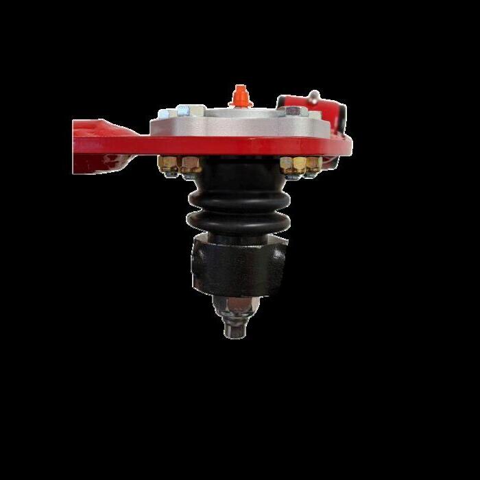
Pumpgreaseintotheballjointzerkfittinguntiltherubberboot juststartstoswell,atleast3-4pumps.
Pumpgreaseintothebushingzerkfittinguntilfreshgrease exitstheEZLubeports.
PumpfreshgreaseintotheballjointsandEzLubeBushingsevery3000-5000milesor afterdeepmud,watercrossings,orheavy off-roaduse.
UseonlylithiummolyfortifiedEPgrease.Usingthewronggreasecanlead toprematurewearandfailure.
APPROVEDGREASEEXAMPLES:
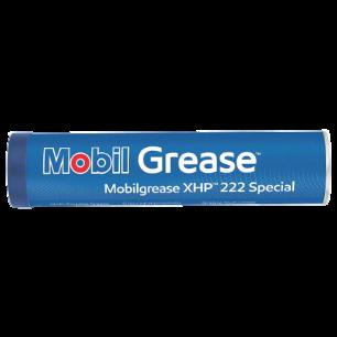
Mobilgrease XHP 222 Special Grease
Chevron EP Moly
OUR#1PICK:
MOBILGREASEXHP222 SPECIALGREASE
Valvoline Multi Vehicle Moly Fortified
REPEATEVERY3-5KMILES
Pennzoil EP with Moly
John Deere HD Moly
Motomaster Moly Extreme Pressure
Shell Rotella SD Moly
Phillips 66 Megaplex XD5
Liqui Moly LM 47 Grease Plus MoS2
Part Number: #JBA-TC-69000-EZ-XX
1.Press the inner bushings into the control arm first.
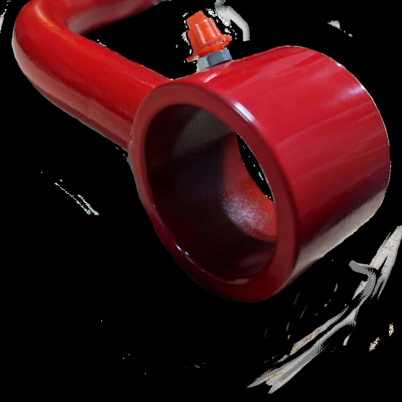
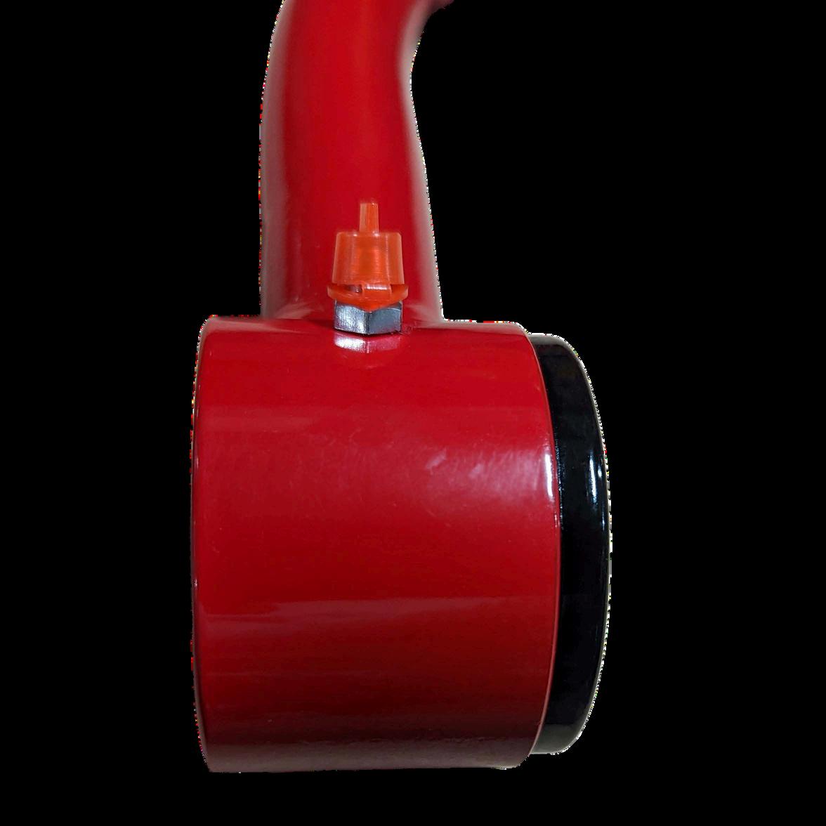
2.Open the supplied grease packet. Apply grease evenly to the inside surface of each bushing bore (¾" inner diameter).
3.Apply a thin, even coat of grease to the steel sleeves.
4.Apply additional grease between the inner bushing faces to ensure the cavity between the bushings is fully lubricated.
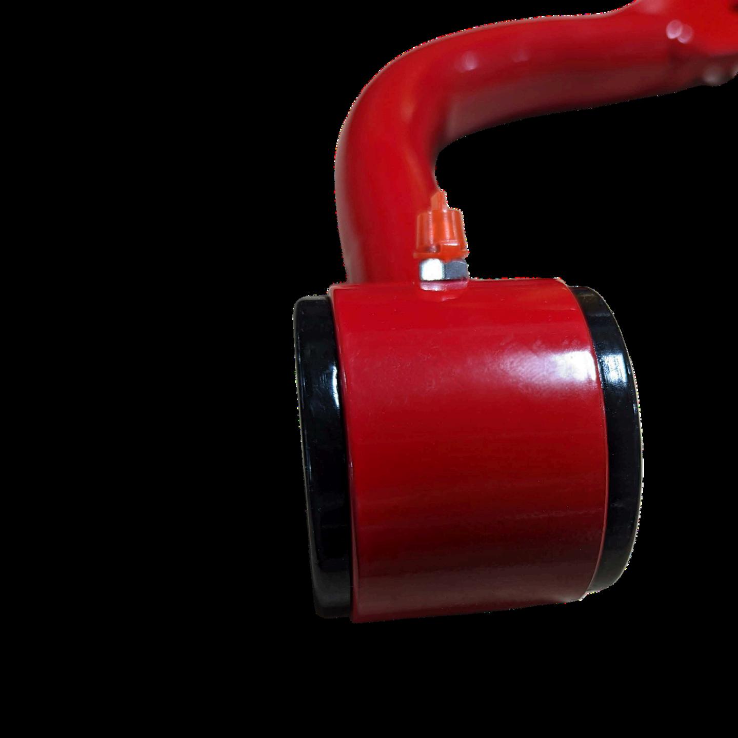
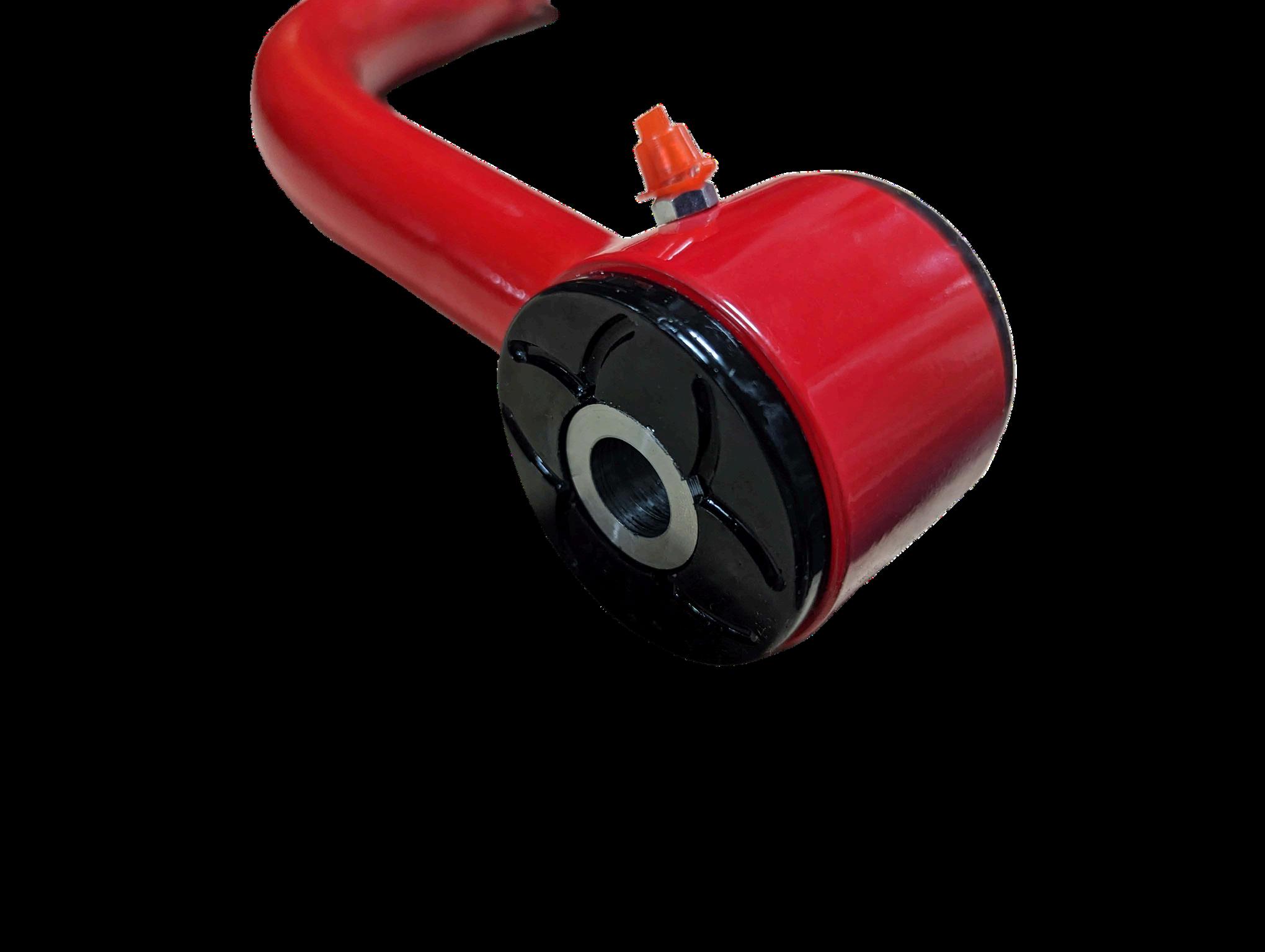
5.Press the outer bushings into the control arm housing until fully seated.
Part Number: #JBA-TC-69000-EZ-XX
6.Install the steel sleeves through the bushings until flush and fully seated.
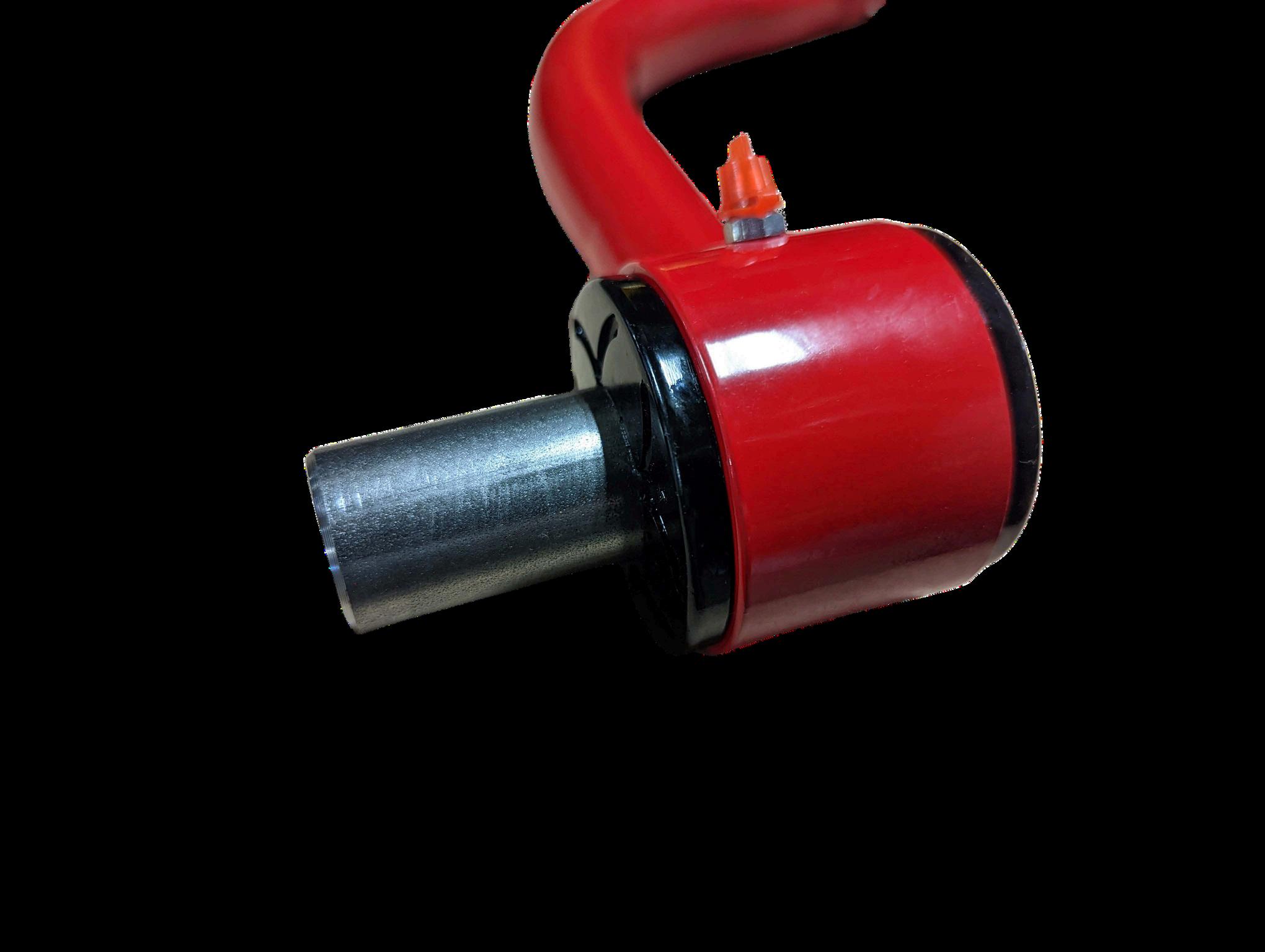
Spread any excess grease evenly around the outer faces of the
8.Continue installation per the Upper Control Arm Installation Procedure.
InstallationDate:
VehicleMileage:
InstallationNotes:
Measurefromcenterofwheelhubtobottomedgeoffenderflare.
DriverSide
Before: After: __________________________
PassengerSide Before: After: __________________________
Every3monthsor3,000-5,000miles.
Mileage: Date:
Mileage: Date:
Mileage: Date:
Mileage: Date:
DriverSide Before: After: __________________________
PassengerSide Before: After: __________________________
Mileage: Date:
Mileage: Date:
Mileage: Date:
Mileage: Date:
Retainyouralignmentprintoutwiththisrecordforfutureservicereference.
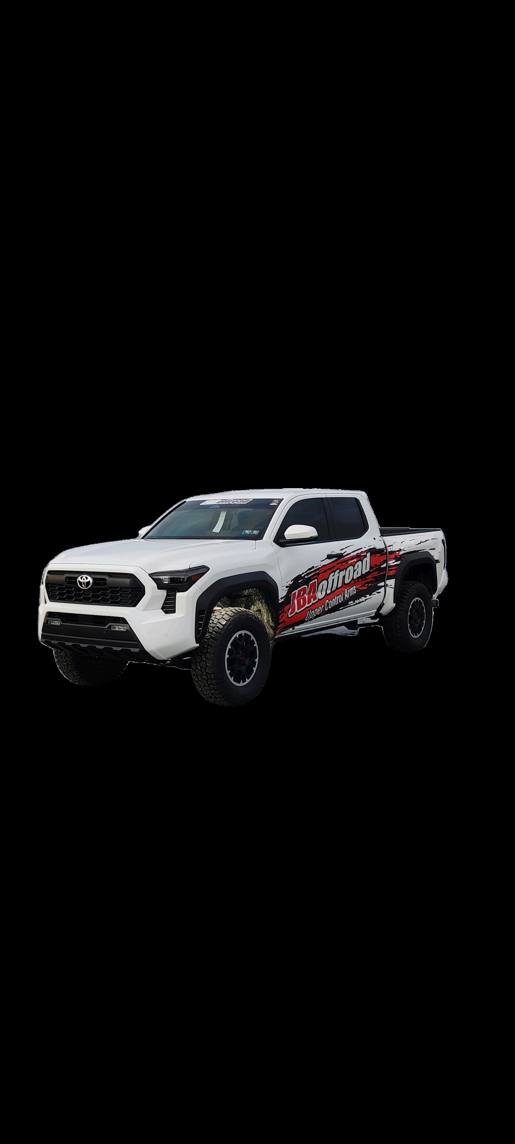
JBAstartedin2004whenAlHandyliftedhisJeep Libertyandthefactoryuppercontrolarmsfailed prematurely.Asanengineer,herefusedtoacceptthat compromisewasnormal.Hedesignedabetterupper controlarm,modeledafterovaltrackracecar geometry,andinstalledthefirstgenerationonhisown vehicle.Onesolutionbecameamission.
Throughmultiplegenerationsofrefinementandexpandedplatforms,that originaldesignevolved.In2007,MarlinGehman’sownershipcarriedthevision forward,improvingserviceability,introducingbolt-inballjoints,andultimately focusingexclusivelyonbuildingthebestuppercontrolarmspossible.Growth didn’tmeanchasingeverything.Itmeantsharpeningourfocus.
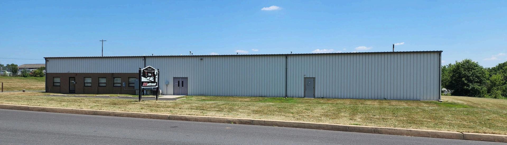
Weareafamily-runcompany,andwestrivetotreatpeoplethewaywewould wantourownfamilytreated.Thatappliestoourcustomers,ourteam,andour partners.
OurChristianfaithguideshowwedobusiness.Forus,thatmeanshonesty, humility,fairness,andkeepingourword.Itmeanstakingresponsibilitywhen wefallshortandworkingtomakeitright.Webelievetheopportunitytobuild andserveothersissomethingwe’reentrustedwith,andwetakethatseriously. Business,tous,isstewardship usingourskillsandresourcesinawaythat reflectsintegrityandrespect.
Ifyouhavequestionsaboutyourparts,installation,maintenance,orfitment, we’regladtohelp.Youcanreachusbyphoneoremailduringregularbusiness hours.
Phone:(215)660-3770
Email:sales@jbaoffroad.com
MailingAddress: 704FormanRoad
CONTACTINFORMATION: BUSINESSHOURS: Monday–Friday 8:30AM–4:30PM Closedonholidays Westrivetorespondpromptlyand respectfullytoeveryinquiry.
Souderton,PA18964
FollowusonInstagram,Facebook,andYoutubeforproductupdates,installs, customerbuilds,ando befeatured:@jbaoffroad
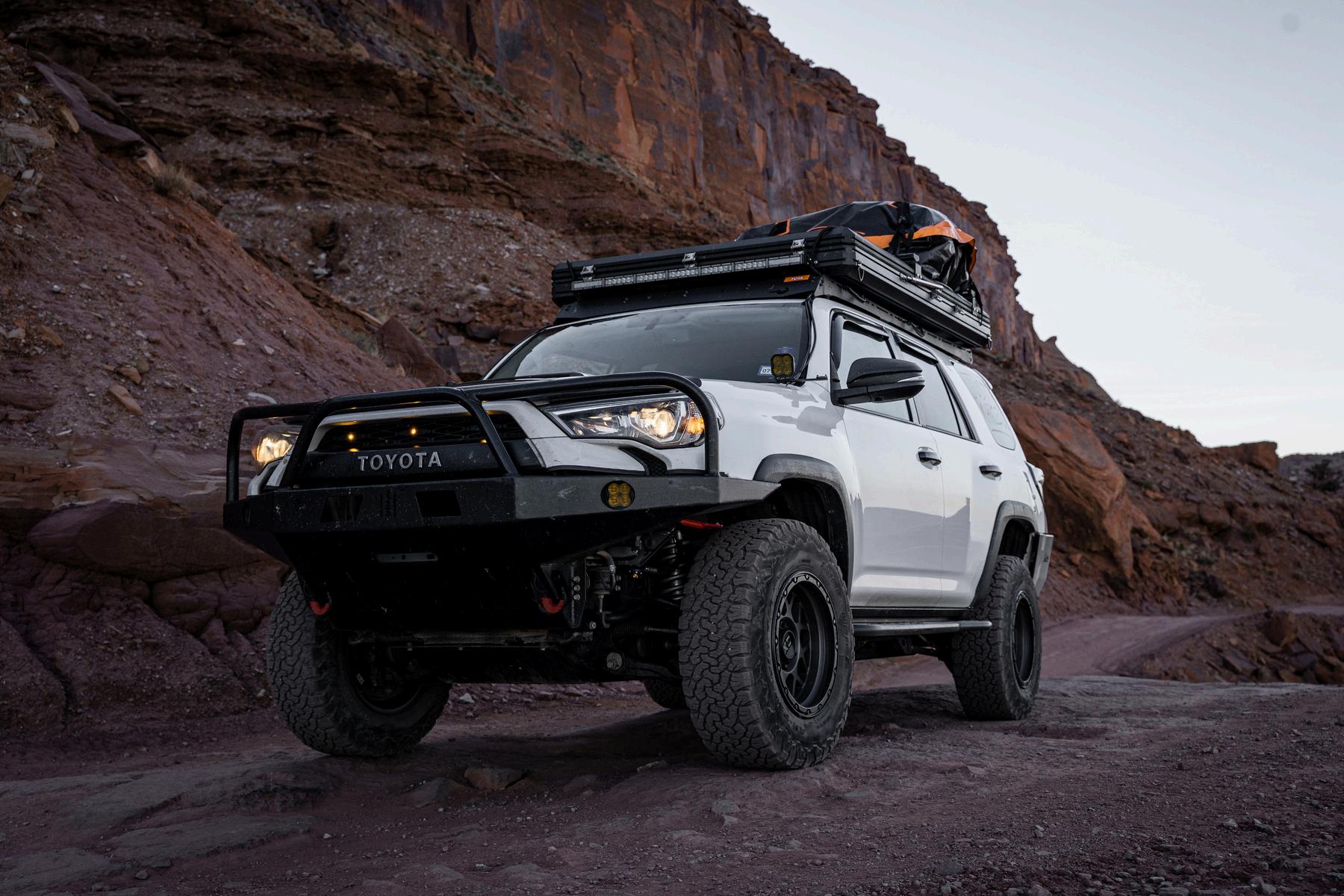
Our FAQ (Frequently Asked Questions) page on our website may have the answers you are looking for - scan the QR code to check!
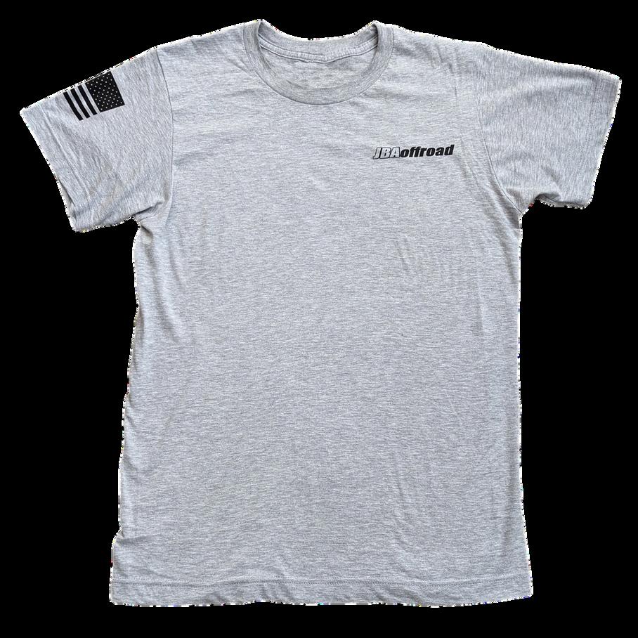
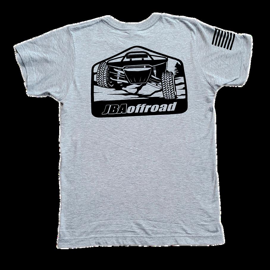
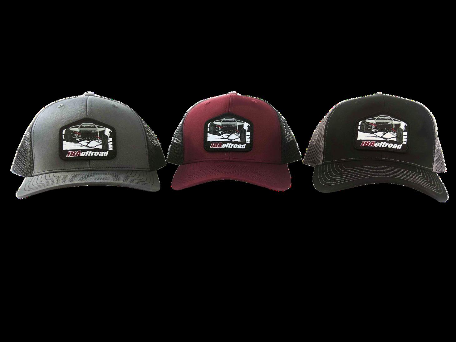
Official apparel and accessories. Built for the shop, the trail, and everyday wear.
Scan to shop the full collection.