14 minute read
15 Tactical Air Navigation (TACAN

from RADIO
(a) System Malfunctions. When the DMC detects a VOR/ILS malfunction, a VOR/ILS avionics built-in test (AVBIT) caution is given.
(b) Built-in Test. The VOR/ILS system contains built-in test equipment (BITE) which is active from when electrical power is applied. The built-in test (BIT) has three modes of operation:
Advertisement
(i) Power-Up Built-in Test. The VOR/ILS receiver does a PBIT when power is first applied or after a power shut-down >5.3 ±0.5 seconds, PBIT duration is <5 seconds. PBIT results are not shown and are thus implemented as part of CBIT.
(ii) Continuous Built-in Test. The VOR/ILS receiver will do a CBIT until power is removed from the receiver. CBIT is performed against the selected mode (including marker), the non-selected mode is monitored for CBIT failures.
(iii) Initiated Built-in Test. An IBIT facility is available through the INITIATE BIT format on the MFD. Selection of the VOR or ILS soft key, depending upon the VOR/ILS receiver frequency selected, will initiate the VOR or ILS and the Marker IBIT. The IBIT will be indicated as follows after 2.5 to 6 seconds:
(aa) The soft key legend will box (The soft key will not box if the DMC cannot communicate with the VOR/ILS receiver).
(ab) The marker beacon valid signals will be shown on the ADI format and the HUD as well as the applicable audio signals.
(ac) The termination of the test will be indicated by the soft key legend being unboxed and the result being shown on the INITIATE BIT format on the MFD. The test result is shown as a PASS (green) or FAIL (red).
16. Checks Carried Out on Hawk Mk-132 A/C. The VOR/ ILS system test is to be carried out in accordance with VT-101B-44132-1M2 MP 72-44/1 and SP 3/5. To carry out the VOR/ ILS system test, the special tools and equipments required are as follows:
(a) IFR 4000 NAV/ COMM Test Set.
(b) Headset, Part No. MT8H550F-B2412 (Qty 2).
(c) PEC, Part No. MBEU72396 (Qty 2).
17. Following checks are carried out on VOR/ILS system:
(a) VOR MODE Check. In this VOR frequency, RF level, VOR TO/FROM, VOR BRG and TONE should be checked.
(b) LOCALISER MODE Check. In this LOCALISER frequency, RF Level and LOCALISER DDM (for left right & 0.093 to 0.200) should be checked.
(c) GLIDESLOPE MODE Check. In this GLIDESLOPE frequency, RF level and GLIDESLOPE DDM (for up &down 0.091 to 0.175), should be checked.
(d) MARKER BEACON MODE. In this mode MARKER frequency, TONE and POWER to be checked.
CHAPTER-15
TACTICAL AIR NAVIGATION (TACAN)
Introduction
1. The Tactical Air Navigation (TACAN) system is a radio aid to navigation. The system provides data in relation to the bearing, slant range, course deviation and time-to-go to a selected transmitting ground station or suitably equipped aircraft. The ground station selected for interrogation transmits an identification code which is heard through the pilot's headset. The system operates up to 300 nautical miles from a TACAN ground station or a co-operating aircraft. Since the TACAN operational limit is restricted to line-of-sight, the actual range is dependent on aircraft altitude.
2. The TACAN operates on any one of 252 channels which are equally divided into 126 X-channels and 126 Y-channels, spaced at 1 MHz intervals. Each channel has two related frequencies, one for transmission and the other for reception. The operating channels have a separation of 63 MHz. The frequency range of the transmitter is 1025 MHz to 1150 MHz and the frequency range of the receiver is 962 MHz to 1213 MHz.
3. Related Systems. The TACAN interfaces with the components/systems that follow:
(a) Communication Control System (CCS).
(b) Radar Warning Receiver system (if fitted) (RWR).
(c) Display and Mission Computer (DMC).
(d) Multi Function Display (MFD).
(e) Head Up Display (HUD).
(f) Data Entry Panel (DEP).
(g) Identification of Friend & Foe (IFF).
Components
4. Transceiver (Fig 15.1).
(b) Function. The transceiver transmits to a beacon or similarly equipped aircraft and receives pulse coded and amplitude modulated signals to determine range and bearing values as follows:
(i) Determines the bearing of the selected TACAN station in relation to the aircraft to give output data for processing and display.
(ii) Determines the slant range to the selected TACAN station in relation to the aircraft to give output data for processing and display.
(iii) Determines the range rate velocity at which the aircraft is flying directly toward the selected TACAN station to give output data for processing and display.
(iv) Receives the ground beacon 3 letter identity as morse code at every 30 sec and gives an audible low frequency morse code output to the headsets.
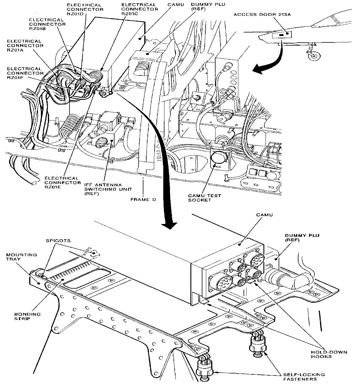
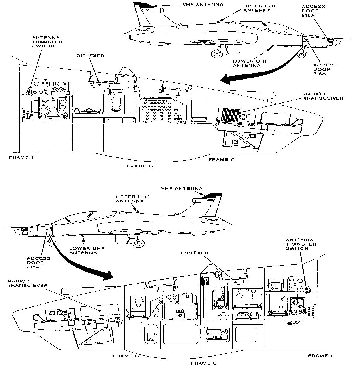
Fig 15.1 Component Locations - Fuselage
(c) Electrical Receptacles. The six receptacles on the transceiver front panel, for electrical and antenna connections to the unit are as follows:
(i) Main connector Power supplies, data bus address and antenna control connector.
(ii) ANT 1 Connector Terminated with 50 Ω dummy load.
(iii) ANT 2 Connector Antenna connector
(iv) BUS AA Data bus A
(v) BUS BB Data bus B
(vi) SUP in/ OUT Suppression pulse connector, to/ from IFF and RWR (when fitted).
5. Antenna.
(a) Location. The antenna is fitted to the bottom of the front fuselage on the centre line.
(b) Function. The antenna is a high speed L-band antenna for use in the UHF frequency band 962 to 1213 MHz. The vertically polarised element is enclosed in a resin reinforced glass fibre shell.
6. Dummy Load.
(a) Location. A 50 ohm dummy load is fitted to transceiver connector ANT 1.
(b) Function. The dummy load provides antenna impedance matching.
7. TACAN ON/OFF Switch.
(a) Location. The two position TACAN ON/OFF switch on the right console in the front cockpit.
(b) Function. When set to ON the switch completes a ground signal to the TACAN transceiver which enables system initialization.
8. Power Supply. Power for the TACAN system is supplied from the 28V DC generator bus bar through fuse 36 on the right supply panel.
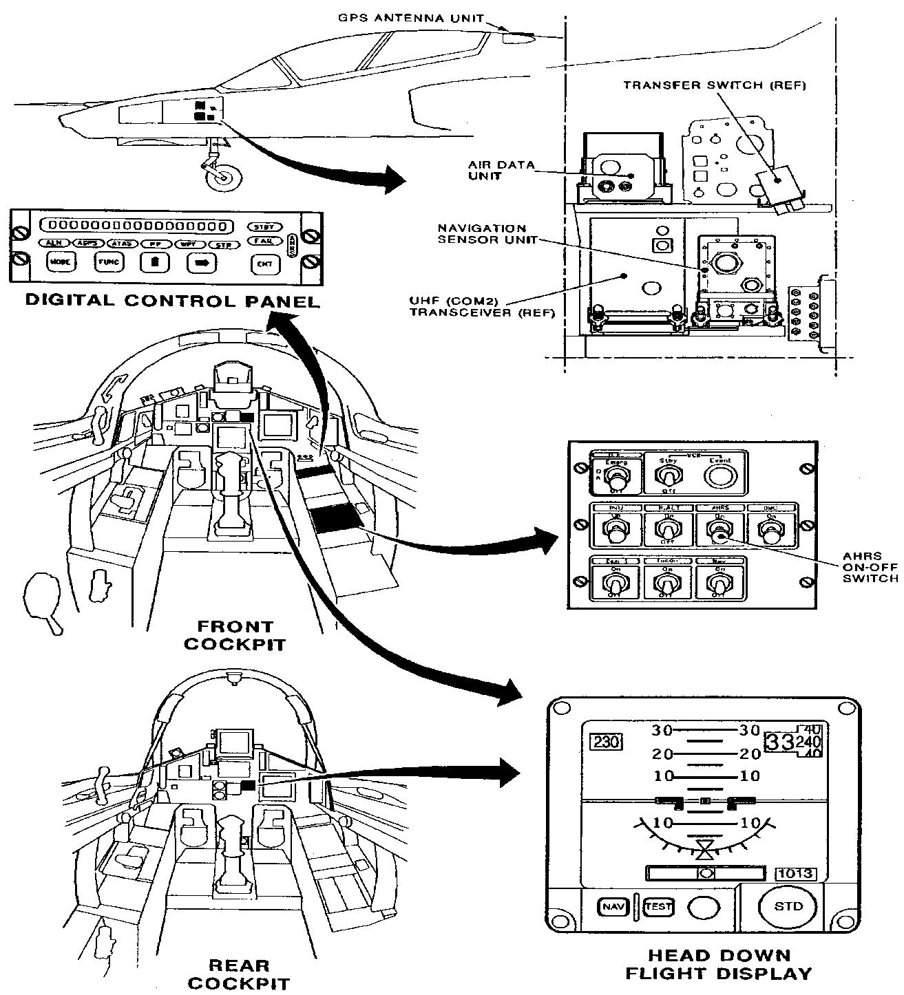
9. Controls and Switches (Fig 15.2). TACAN functions are controlled through:
(a) Multi-Function Display. TACAN system parameters are shown and controlled through the CNI MENU and RNAV formats of MFD.
(b) Data Entry Panel. The DEP has push-button keys that let the operator control system modes and edit or enter alphanumeric data as required. The data is shown on a scratchpad on the HUD.

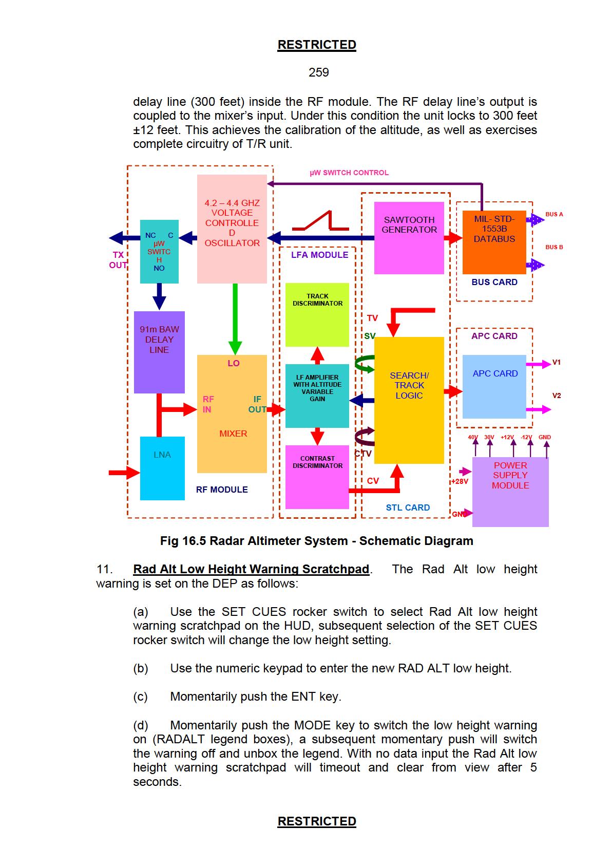
Fig 15.2 TACAN System - Schematic
(c) Audio Control Panels. The TACAN audio and volume is controlled on the ACP. A push-button switch labelled TAC selects the audio to the headset and the TACAN audio volume is controlled with the NAV rotary control.
(d) CRS/HDG Switch. A course/heading switch is fitted to both front and rear cockpit instrument panels. The control is used to move respective symbology on the MFD as follows:
(i) Course Control. Selection of CRS +/- changes the required course input to the navigation system. On the MFD HSI format the course line is rotated with the control and on the ADI format the course pointer is rotated. When MFD MAP formats are shown, the control is used to rotate course line about the steer point.
(ii) Heading Control. Controls the position of the manual heading index on all MFD primary flight formats. HDG R moves the heading index in a clockwise direction around the compass rose. HDG L moves the heading index in a counter-clockwise direction around the compass rose.
Operation
10. Modes of Operation (Fig 15. 3). The DME is a secondary radar system providing slant range by pulse technique. The aircraft interrogator transmits a steam of Omni directional pulses on the carrier frequency of ground transponder and on ground the received interrogation are retransmitted with a delay of 50 µs. The airborne equipment identifies the reply and measure the time interval between transmission and reception pulses. The width of interrogation pulse is 3.5 µs and they are transmitted in pairs (The interval between individual pulses of pair is 12 µs for X channel and 36 µs for Y channel). The TACAN system has three modes of operation as follows:
(a) Air-to-ground Receive Mode (RX). In the receive mode the system receives identification and bearing data signals from a selected ground station. From the received signals, course deviation and TO/FROM data can also be derived for processing and display.
(b) Air-to-ground Transmit/Receive Mode (T/R). In the T/R mode the system receives signals as in the receive mode. In addition, the transceiver transmits interrogation pulses to trigger the ground station. The transceiver receives a reply pulse and the slant range distance is calculated from the signal.
(c) Air-to-Air Mode (A-A). In the air-to-air mode, the system interrogates a co-operating aircraft and receives and calculates bearing and slant range data. If the interrogated aircraft is not suitably equipped, only slant range is calculated. In this mode the system transmits distance replies to other aircraft, when interrogated.
(d) When operating in the air-to-air mode, for an aircraft to be considered as co-operating. The TACAN channel selected in the cooperating aircraft must have a channel separation of at least 63 channels from the host aircraft TACAN channel. Bearing data is only available if the other aircraft TACAN installation has bearing transmission facilities.

(a) Multi Function Displays. TACAN parameters are shown on the CNI MENU and RNAV formals on the MFD. TACAN parameters are set through the TACAN RNAV formats.
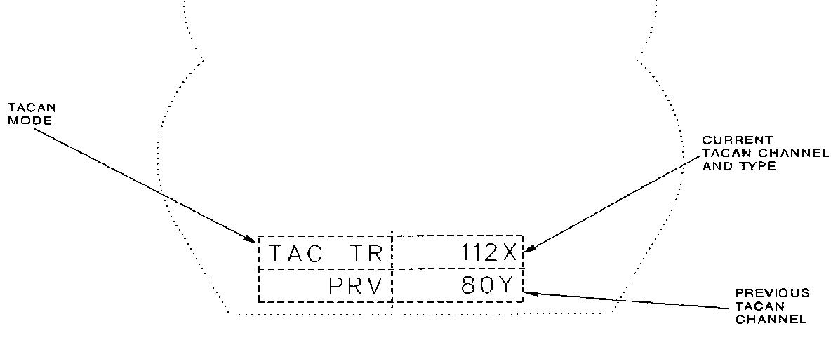
(b) CNI MENU Format (Fig15.4). The CNI MENU format shows the current TACAN channel and mode of operation. If the TACAN is off or has malfunctioned the channel and mode information is not shown. A momentary push of the RNAV soft key will show the RNAV format.
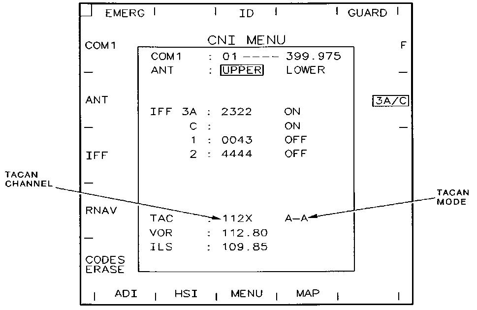
Fig 15.4 MFD CNI MENU Format
(c) RNAV Format (Fig15.5). The RNAV format is selected from the CNI MENU formal and shows TACAN, VOR and ILS information. When TACAN is off or has malfunctioned, channel and mode information is not shown. Table 1 lists the RNAV format soft key functions.

Soft key Legend Function
1 CNI MENU Selects CNI format 2 TAC Selects RNAV (TAC) format. TACAN scratchpad is shown on HUD and legend boxes. When legend is boxed, momentarily pushing soft key will, Unbox legend and show RNAV format. Remove TACAN scratchpad (when shown) and terminate data entry sequence. 3 VOR Selects RNAV (VOR) format. VOR scratchpad is shown on HUD and legend boxes. Soft key is not available if VOR/ILS unit is off or malfunctioned 4 ILS Selects RNAV (ILS) format. ILS scratchpad is shown on HUD and legend boxes. Soft key is not available if VOR/ILS unit is off or malfunctioned 6 ADI Selects ADI format 7 HSI Selects HIS format 8 MENU Selects MENU format 15 F,R, AVBIT TEMP Refer MFD Menu Format 18 ID Selects IFF system 'identification of position' mode.
(d) RNAV (TAC) Format (Fig15. 6). The RNAV (TAC) format is shown when the TAC soft key on the RNAV format is momentarily pushed and boxed. The format provides TACAN channel switching, control functions and access to TACAN mode selections. Table 2 lists the soft key functions in addition to these listed under the RNAV format in Table 1.

Soft key Legend Function
3 PRV CHAN
Toggles between current and previous TACAN parameters, as shown on RNAV formats and TACAN scratchpad 4 MODE Selects RNAV (TAC-MODE) format 11 X/Y Toggles TAC channel between X and Y. Only available when TAC soft key is boxed and TACAN scratchpad is shown. Not available when ranging function is selected and current operating TAC channel is being edited
(e) RNAV (TAC-MODE) Format (Fig 15.7). The RNAV (TAC-MODE) format is shown when the MODE soft key on the RNAV (TAC) format is momentarily pushed. The format provides TACAN mode control. Table 3 lists the soft key functions in addition to those listed under the RNAV format in Table 1.

Fig 15.7 MFD RNAV (TAC-MODE) FORMAT
Table 3 RNAV (TAC-Mode) Format Soft Key Functions/Indications
Soft key Legend
Function
2 RX Selects TACAN to air-to-ground receive mode and returns MFD to RNAV (TAC) format. RX legends on both RNAV and CNI MENU formats will be boxed. 3 T/R Selects TACAN to air-to-ground transmit/receive mode and returns MFD to RNAV (TAC) format. T/R legends on both RNAV and CNI MENU formats will be boxed. 4 A-A Selects TACAN to air-to-air mode and returns MFD to RNAV (TAC) format. A-A legends on both RNAV and CNI MENU formats will be boxed.
(f) TACAN navigation data is shown on three main formats on the MFD as follows:
(i) MAP. The MAP format (Fig15.8). Encircled with a compass rose, represents the horizontal position of the aircraft in relation to destinations. Additional data is shown which includes digital readouts of course, bearing and groundspeed. When valid TACAN data is received, a TACAN bearing pointer is shown on the compass rose to give a related bearing indication to the selected TACAN station. A TAC caption is shown on the left as soft key allocation for TACAN steering selection.
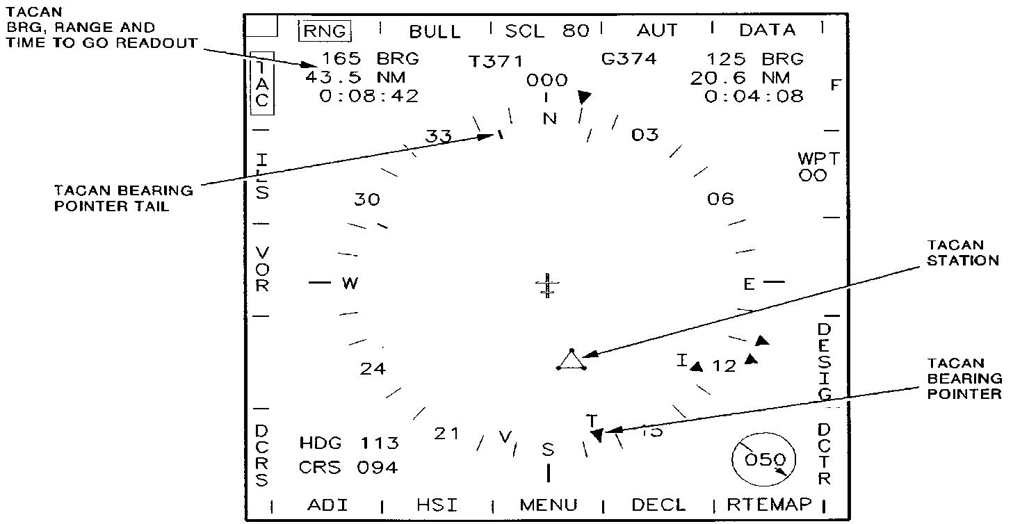
Fig 15.8 MFD MAP
(ii) HSI. The HSI format (Fig 15.9), includes a compass rose, bearing and selected course pointers. A deviation indicator to give conventional course deviation and TO/FROM indications. Additional data includes digital readouts of course, bearing and groundspeed. When valid TACAN data is received, a TACAN bearing pointer is shown on the compass rose to give a related bearing indication to the selected TACAN station, the reciprocal of this bearing is indicated with a tail. A TAC caption is shown on the left as soft key allocation for TACAN steering selection.

Fig 15.9 MFD HSI Format
(iii) ADI. The ADI format (Fig15.10), shows aircraft attitude. Additional data includes digital readouts of course, bearing and groundspeed. When valid TACAN data is received a TACAN bearing pointer is shown on the compass rose to give a related bearing indication to the selected TACAN station. A TAC caption is shown on the left as soft key allocation for TACAN steering selection.

Fig 15.10 MFD ADI Format
(g) TACAN Steering. When the TAC soft key, available on the MFD MAP, HSI and ADI formats is selected, or TACAN edit via DEP is terminated with a momentary push of the GOTO key, TACAN derived
data for navigation and display purposes will be selected. The TAC soft key legend is boxed and the steering bug changes colour from cyan to white. The data that follows is also shown.
(i) MFD MAP Format.
(aa) A digital readout of the bearing in relation to the currently selected TACAN station.
(ab) Course line/demanded track to the selected TACAN station, and direction of track demand arrow.
(ac) Digital readout of range and time to go to the selected TACAN station
(ad) TACAN bearing pointer, shows bearing to the TACAN beacon when read against the compass rose. The position of the TACAN station in relation to the aircraft present position.
(ii) MFD HSI Format.
(aa) A digital readout of the bearing in relation to the selected TACAN station.
(ab) TACAN bearing pointer shows bearing to the TACAN beacon when read against the compass rose.
(ac) Digital readout of range and time to go to the selected station.
(ad) Selected course pointer and course deviation indications with TO/FROM indication.
(iii) MFD ADI Format.
(aa) Digital readout of the bearing in relation to the selected TACAN station.
(ab) TACAN bearing pointer, shows bearing to the TACAN beacon when read against the compass rose (TACAN pointer tail is not shown on the ADI format).
(ac) Digital readout of range and time to go to the selected TACAN station.
(iv) When TACAN data becomes invalid the TAC soft key changes colour to amber and the invalid data is removed. A related
TACAN INVALID message is shown (in amber), on the MFD HSI, ADI and MAP formats for 5 seconds as follows:
(aa) TACAN bearing and range invalid "TACAN INVALID" is shown.
(ab) TACAN bearing invalid "TACAN BRG INVALID" is shown.
(ac) TACAN range invalid "TACAN RNG INVALID" is shown.
(v) When TACAN is selected as the RNAV aid, the RNG soft key on the MFD MAP, HSI and ADI formats will box. The soft key will remain boxed when TACAN is the active RNAV aid for steering. Range and time-to-go is shown when valid.
(h) Head-Up Display (Fig 15.11 & 15.12). The display is presented in multi-selectable formats. TACAN radio navigation data is shown in the general navigation format (Fig.15.11) when TACAN is the selected steering aid. The general navigation format primarily shows steering data to a selected destination and also gives other flight display data. The format includes course deviation indicators, when the TACAN is selected in relation to the current TACAN station. When TACAN is selected, a TAC legend replaces the steer point number.