6 minute read
Load Sensing Device (LSD)


BOBR/ETAP/BCCW & BLC wagons are provided with automatic two stage empty load device to cater for higher brake power in loaded condition instead of the conventional manual empty load' device. With the provision of this, brake cylinder pressure of 2.2 kglcm² is obtained in empty condition and 3.8 kglem2 is obtained in loaded condition.
So as to obtain this a changeover mechanism called "Load Sensing Device" (LSD) is interposed between the bogie bolster and spring plank. The mechanism gets actuated at a pre-determined change over weight and the distributor valve which has the additional feature (Le.EK PT/C32) controls the brake cylinder pressure.
Advertisement
Automatic Pressure Modification
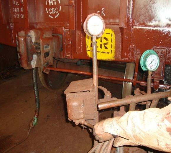
1. APM device is interposed between bogie side frame of Casnub bogie and the under frame of wagons.
2. APM should sense the gap only at the time of air brake application. 3. During remaining time it should not be in contact with the bogie side frame.
Rake Test can be performed by using a portable device called "RAKE TEST RIG". The test rig provides all facilities like a locomotive to conduct the test.
The rake test rig has air supply and mobile test rig. The mobile test rig is having a cubical structure and is mounted on wheels. It can be taken to the yard.
A rake consisting of 60 wagons can be tested with this rig. This rig may be used for testing the train in yard before attaching the engine.

Single Wagon Test
• Couple up all Brake Gear Fittings properly.
• Keep the handle of the Empty Load Box in "Empty" position and keep the Hand Brake Handle in the "Off" position.
• Move SWTR near to the Wagon and connect Brake Pipe of the Wagon to SWTR.
• Dummy the other end of the Brake Pipe at Palm end of the Hose Pipe.
• Fit a Pressure Gauge on Brake Cylinder.
• Connect SWTR to the main source of Air Compressor with 6 - 10 kg/cm2 capacity.
• Set the Pressure Regulator to 5 kg/cm2
• Open the Cut off Angle Cocks on both ends of the Wagon.
• Keep Brake Valve in charging position and charge the Wagon at Brake Pipe Pressure of 5 ± 0.1 kg/cm2. If there is drop in pressure, locate the leakage with Soap Water and arrest it by changing the "O" Ring.
• To check the leakage in Brake Pipe close the cocks for 1 minute and then open them. Allow leakage of 0.1 kg/cm2 for 1 minute.
• Bring Brake Valve in position for full service application. Brake should apply with a pressure drop in BP by 1.3 to 1.6 kg/cm2 in 18 to 30 secs.
• Record time for filling air to the maximum pressure in Brake Cylinder of3.8 ± 0.1kg/cm2 Record the Piston Stroke of Brake Cylinder. It should be 85 ± 10 mm for Empty and 130 ± 10 mm in Load Position.
Testing Procedure For Dirt Collector
• Mount the dirt collector on base of the test bench.
• Close two openings on the dirt collector using dummy flanges. Keep cooks (2) and (3) closed .Open cock (1)
• Charge the reservoir to 10 kglem
• Open cook (2), check the pressure at BP pressure gauge. It
• should be equal to 10 kg/cm³.Close cock (2)
• Check for leak over the body and joints with the help of soap solution, no leak is permitted.
• Also check for pressure drop in BP pressure gauge for 3 minutes. Pressure in the BP pressure gauge should be maintained.
• Open cock (3) and exhaust the pressure to zero. Remove the dummy flange from the outlet port
• The pressure will soon exhaust through the outlet port.
• Remove the dirt collector from the test stand.
• In case of leakage. Reassemble the joints after replacing defective components and retest.
• Report Results ,Safety Precautions
• The assembled dirt collector should be stored in such a way to prevent the following: Flange surface should be prevented from damage.
• Inlet and outlet port should be plugged with protective caps toprevent the entry of moisture and dirt inside the dirt collector.
• Specified tools and fixtures should be used for handling.mounting and removing the dirt collector from the test bench. The small metal parts like screws, nuts, bolts, washers etc. should be kept in a safe place and replaced in case found defective
TESTING PROCEDURE FOR CUT-OFF ANGLE COCK
Following out procedures should be sold step by step for performing the leakage test
Mount the angle cock saw the base of the test been Part of the of the test bench)
Move the handle to the closed position
See that cock (1) and (1c) are in closet position in now open cock 1) and 11 indicate as of 10 Kg/m2
If necessary, adjust pressure regulator (2) to maintain the pressure at 18 C Open cock (14) and chock the leakage with snap solution. There should not be any leakages drop in gauge (6b) there should not be any leakage from flange joints
Check pressure vent and port of the angle cock. Will Close cock (1c) and tighten the dummy plug and seal the out the angle c it Move the handle to open position. Open cock 1
1. Check pressure leakage from body and cap joint vent and all over the semi periphery sing soap west. Leakage is permissible Move the handle to closed position and notes a short blast of ale through the vent all. Remove the angle cock, Report results of the test
Safety Precautions
Specified jigs and fixtures should be used for assembly and disassembly operations
The metal parts like leaf spring, nut, washers, screws at should be halt In a safe place and replaced in case found defective net and outlet port of the tested angle cock should be plugged with protection cap to prevent entry of dost and moisture inside the cut off angle cock.
Tools and Equipment Test Bench
Compressor to build pressure more than 10 kglom2. Single ended spanner as per 15 2027

Across face 17 (for M12 lock nut)-1 No b) Across Fans 13 (for Mil studs) 2 Na Screw Driver-300mm, 1 No.
1 BSP dummy Plug with seal.
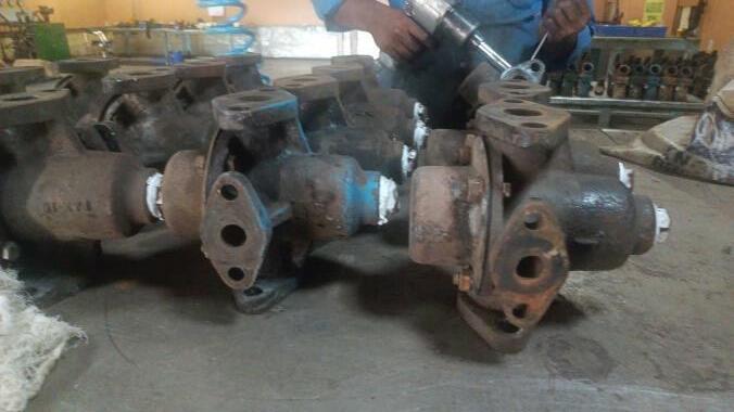
Testing Of Distributor Valve
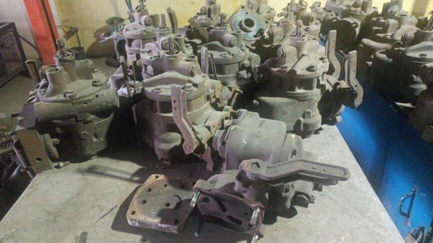
For the proper functioning of the Air Brake System, it is necessary to test the Distributor Valve. The following tests are carried out to ensure the proper functioning of Distributor valve: The following tests are conducted on the distributor valves:
• Pressure tightness test – (during charging, application and release test & emergency application test).
• Charging time.
• Full service application and release.
• Overcharge protection test.
• CR overcharge reduction test
• Emergency application.
• Sensitivity test.
• Quick service test.
• Insensitivity test.
• Re-feeding test.
• Graduated application test.
• Graduated release test.
• Quick release test
• Control reservoir check valve reset test.
Testing Procedure Of Brake Cylinder
Strength test:
• Place the brake cylinder on base (4) and connect the line.

• To brake cylinder. Brake cylinder stroke should be free. Close the safety guard, close the cock (IC).
• Open cock (1b) and let reservoir pressure reach 10 kg/cm2 Check the pressure in MR gauge (3a). Open cock (2) till-the pressure reaches 6 kg/cm2 in pressure gauge (3b) Close the cock (2) and wait for 2 minutes.
• 1.6 Open cock (le). The above test should be done with the safety guard.
Pressure tightness test:
• Mount the cylinder on the test stand and tighten the mounting
• Bolts & nuts. 2.2 Set the brake cylinder stroke at 85+ 10mm. 2.3 Open cock (2) and let the pressure gauge (3b)
• Reaches 0.8 kg/cm2. 2.4 Close the cock. (2) And wait for 1 minute till the pressure stabilize in gauge (3b).
• Check for the pressure drop which should not be more than 0.1 kglcm2 in 10 minutes.
• Open cock (c) .Repeat the test at 130+ 10mm piston stroke and 3.8 kg/cm2 pressure. Close cock (2) open cock (1c). Remove the Brake cylinder.
• If operation is not correct or leakage rate is higher, dismantle the brake cylinder and examine piston packing wear ring for proper fitment, examine plug for leakages. Reassemble the components and retest.
Multistage Distributive Valve Cleaning Machine

Process:
• Entry
• Pre wash – 6min (oils- R200 , Kaizen)
• LTST – Lateral Trust Surface
• Ultrasonic rays
• Rinser - ARP 3600 oil
• Dryer
• Exit
ADVANTAGES OF TWIN PIPE OVER SINGLE PIPE AIR BREAK SYSTEM
• With a dual reservoir system, the brake circuits are split into front and rear, and in the event of a failure, you have a much better chance of safely stopping the vehicle.
• Supply of air is unlimited, so the brake system can never run out of its operating fluid, as hydraulic brakes can. ...
• Air Line couplings are easier to attach and detach than hydraulic lines; the risk of air getting into hydraulic fluid is eliminated, as is the need to bleed brakes when they are serviced.