Since its establishment in 1987 in Five Dock, NSW, Independent Timber Importers (ITI) has been on a mission to redefine the timber wholesale and distribution landscape. ITI has worked closely with industry suppliers, customers, and associations to promote the strength, beauty, and environmental benefits of timber construction.
At the same time, ITI redefined the role of the wholesaler through its distribution and service models. With significant investment in distribution centres, product development, people, and service standards, ITI transitioned from the name Independent Timber Importers in early 2002, adopting the ITI brand and introducing the “Innovative Timber Ideas” logo to more accurately reflect the company’s philosophy.
Today, ITI operates nine distribution sites across Australia with over 140,000 m2 of undercover storage, a state-of-the-art re-manufacturing, treating, and priming facility in Chile, an office in Indonesia, four distribution locations in New Zealand, and a growing presence in the United States.
True to its name, ITI’s success lies in its commitment to innovation in both service and product development. This commitment has led to the creation of premier brands such as Design Pine, EziTrim Plus, and Spec Frame, along with the distribution of market-leading products including James Hardie, Weathertex, and ModWood. ITI has also been recognised with numerous industry awards for service excellence.
ITI Engineered Wood Products
ITI sources engineered wood products from leading manufacturers to ensure the needs of building designers through to end users are met with high-quality, reliable solutions.
The ITI Engineered Wood Products range comprises three primary systems, each designed to complement the next: Laminated Veneer Lumber (LVL), I-Joists, and glue laminated timber beams (GL). These products, together with innovative construction details and dedicated technical support staff, form an integrated platform that sets ITI Engineered Wood Products apart.
Single Member Design Software
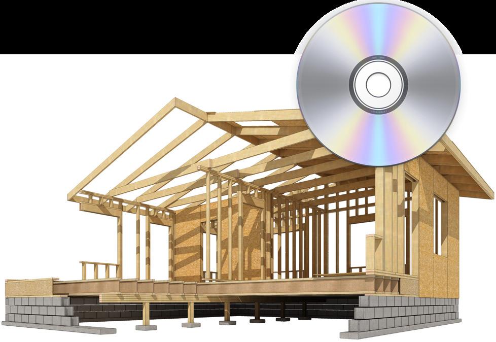
ITI Design Spec is a single-member design software package developed to assist industry professionals with the specification of ITI’s extensive range of structural timber products. Free licences are available for builders, timber merchants, frame and truss manufacturers, and engineers.
Hyne Design is a free-to-register structural design platform suitable for timber designers of all experience levels. The platform enables the specification of ITI and Hyne Timber’s broad range of structural timber products.
Email ewp@iti.net.au for details on how to access.
Note: Users must meet the requirements of the ABCB Structural Software Protocol to obtain access.
Hyne Design is a free to register structural design platform for timber designers of all experience levels a tool to specify ITI and Hyne Timber’s broad range of structural timber products. To request access please email ewpvic@iti.net.au
Note: Users are required to meet the requirements of the ABCB Structural Software Protocol to obtain access.
SPECBEAM13.2
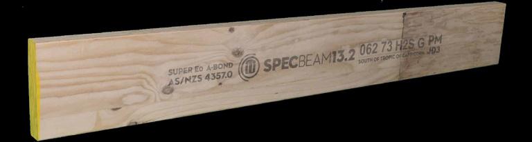
Spec Beam® 13.2 is an economical LVL E13.2 solution, available in all commonly specified sizes used by engineering professionals. The range provides suitable options for beams, rafters, and joists across residential and light commercial applications.
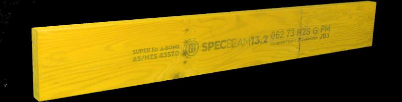
Spec Beam® 13.2 is supplied with a light sealant coating for temporary protection against the elements during construction and features pencil-round corners for splinter-free handling and ease of installation.
(1)
(2)
(3)
for
(5) The applicable Joint Group is printed on each piece of Spec Beam 13.2
It is a requirement of the Australian standard for manufacturing Laminated Veneer Lumber that an external A bond be achieved between the veneers by using a phenolic type adhesive.
Production Testing
Spec Beam® LVL is subject to more than 70 quality control checks from log receipt through to export of the finished product. Structural performance is verified through destructive bending tests every two production hours and bond strength testing every four production hours.
All Spec Beam® manufacturing facilities are audited twice annually to verify the effectiveness of quality assurance systems and production controls.
Ethically sourced wood fibre
Suppliers responsible for the provision of logs used in the manufacture of Spec Beam® LVL are required to demonstrate compliance with the Australian Illegal Logging Prohibition Act.
The wood fibre used in Spec Beam® 13.2 LVL is sourced from Pinus massoniana (China), or Picea abies (Europe)
FSC® certification is available upon request.
laminating multiple LVLs
Nail Lamination of 2-Ply & 3-ply Ply Members
NAIL LAMINATION NOTES:
Nail Lamination - 2-Ply & 3-Ply Members
Minimum Nail Sizes
45mm Members - 2.80x75mm
1. Minimum 2 rows of nails for all depths up to 290mm
2. Drive opposing nail pattern to opposite side of member
3. Nails to penetrate second member by at least 50%
4. First nails to be located approximately 135mm from the edge
5. Provide two additional nails under point loads and over supports
Bolt Lamination of 2-Ply & 3-Ply Members
2 Ply Lamination requires 2 Rows of Bolts
3 Ply Lamination requires 3 Rows of Bolts
BOLT LAMINATION NOTES:
1. M12 (8.8/S) bolts with 55mm washers at 600mm centres staggered in 2 rows for 2 ply beams
2. M12 (8.8/S) bolts with 55mm washers at 600mm centres staggered in 3 rows for 3 ply beams
3. Minimum 60mm edge clearance required
4. Ensure pre-camber of Glue Laminated Beams is set in the upward direction
5. Apply an additional 2 or 3 M12 bolts directly under any point loads
6. Bolt members together prior to applying loads
SCREW CONNECTION
Screw Lamination of 2-ply & 3-Ply Members
SCREW LAMINATION NOTES:
1. Detail applicable to a 14g Bugle Head Batten Screw
2. Not acceptable for 2-ply 45mm members
3. Drive opposing screw pattern to opposite side of member for 3-ply configurations
4. Not acceptable for members less than 200mm in depth
5. 3 Rows for 3-ply configurations
6. Refer to table for minimum edge and end distance requirements
7. Minimum of 45mm embedment into second member required
8. Suitable for both face and top loaded members
Roof Batten to Rafter Connections
D/3 max.
holes & notches in lvl
D/2 max.
6 x B min. B/4 max.
D/4 Max.
100mm Max.
Notch may be over support
Notch may be over support
D/2 max.
100mm Max.
D/8 max. No min.
D/8 max.
min.
D/4 max
D/3 min.
D/3 min.
D, less than 200mm
D/8 or 25mm max.
D/8 or 25mm max.
Notes:
D/2 or 100mm max. D/6 min.
D/2 max.
D, 200mm+ 50mm max.
1. No more than 2 holes are permitted within an 1800mm length
2. For more information refer to AS 1684 Section 4.1.6.
Greater than Hole Dia. 50mm min.
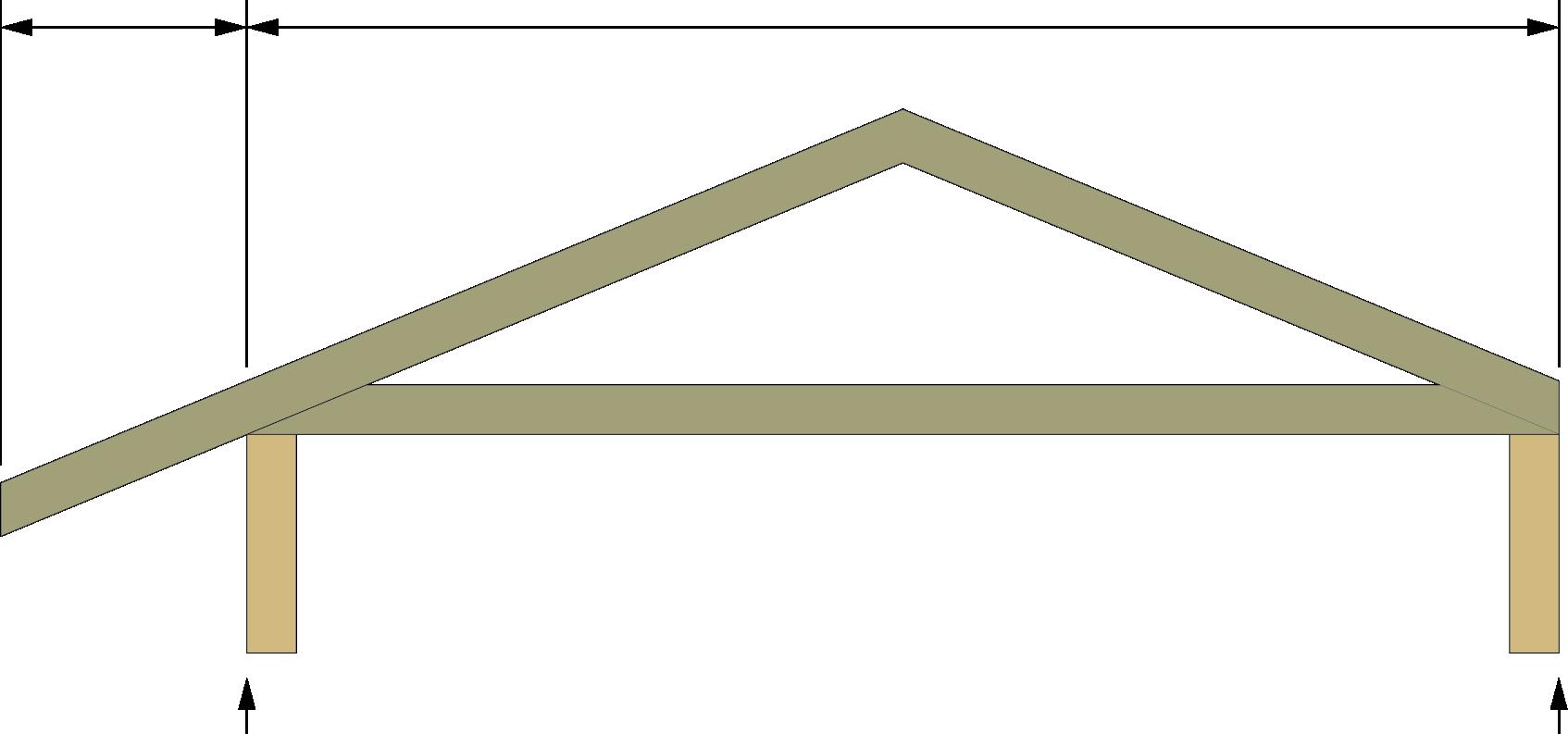
ROOF LOADINGS & DEFINITIONS
Determining Roof Load Width (RLW) at Supports - Trussed Roof
Overhang
Determining Roof Load Width (RLW) at Supports - Pitched Roof
Determining Ceiling Load Width (CLW) at Supports
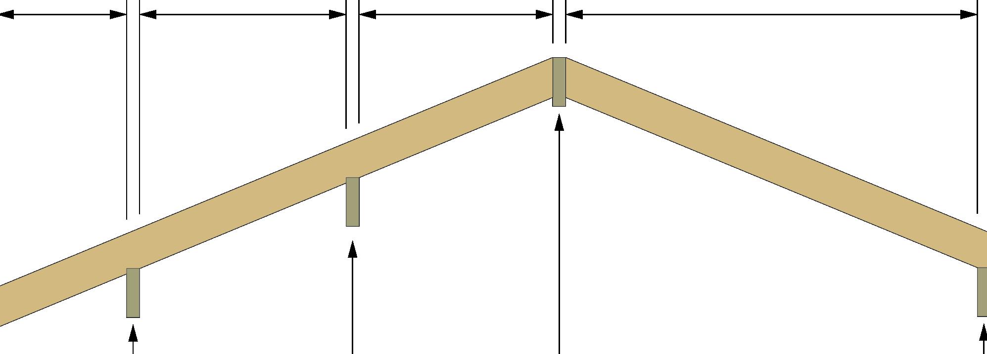
Rafter & Beam
Single Span Continuous Span
Span A
Single Span Continuous Span
Span A
Span A
Span A
Span B
Span B
A continuous span only applies when the smaller of the spans is no less than half the larger span. Where this does not apply; both spans are to be treated as singles spans or further design analysis is required. Measure spans between internal faces of the supports.
Lateral restraint to Counter, Hanging and Strutting Beams
(a) Block skew nailed to beam and support with 3/75mm framing nails to each member.
(b) Minimum 35x32mm tie nailed to the top of the beam and to the support with 2/75mm framing nails at each end.
Rafter
(c) G.I. Strap looped over beam with 2/30x2.8mm nails at either end and into the beam.
/ Taper Cut to Counter, Hanging and Strutting
Beams
17.5o Minimum cut angle
The greater of ‘D’/3 or 100mm
Roof beam ends may be taper cut to avoid interference with roof coverings. It may be necessary to cantilever roof battens and butt into the side of these members. This detail may be used for Counter, Hanging, Strutting Beams as well as combination Strutting / Counter and Strutting / Hanging Beams.
FLOOR LOADINGS & DEFINITIONS
Floor Framing Deflection
Examples:
Maximum Dead Load Deflection on a 6000mm span is 15mm as 6000/300=20mm which exceeds the 15mm limit.
Maximum Floor Live Load Deflection on a 3000mm span is 8.3mm as 3000/360=8.3mm which is below the 9mm limit.
Bearer & Joist Span Types
A continuous span only applies when the smaller of the spans is no less than half the larger span. Where this does not apply; both spans are to be treated as a singles span or further design analysis is required. Measure spans between internal faces of the supports.
Determining Floor Load Width (FLW) at Supports
Cantilever
FLOOR JOISTS & BLOCKING
Floor joists are structural members installed in parallel and designed to support floor loads. Joist spacing must comply with the requirements of the supported flooring system.
Blocking Type
1 Intermittent blocking over external support at start / end of joist run
2 Intermittent blocking over internal support at start / end of joist run
3 Intermittent blocking over external support at 1800mm centres
4 Continuous Blocking to cantilevered joists
5 Rimboard / Fascia Beam to ends of cantilevered joist
Blocking is used to provide lateral restraint to joists and to transfer concentrated loads into the supporting structure.
Common Studs
Full Height Blocking min. 35mm Thick
Blocking to Concentrated Loads
Concentrated Load
Bottom Plate
Floor Joists
Support Framing
Blocking provided to resist concentrated loads must be full height and a minimum of 35 mm thick. This blocking transfers applied loads into the supporting framing system below.
Nominal joist to support fixing
(1) Where additional uplift is not generated through abnormal span conditions or imposed loads. Refer to AS1684 for additional details where tie-down is required
FLOOR JOISTS
Refer to page 50 for specification notes
FLOOR JOISTS
FLOOR JOISTS
FLOOR BEARERS / TRIMMERS
Floor bearer or trimmer
Floor bearers and trimmers are structural members that run perpendicular to, and support, floor joists. Floor joists may be supported either on top of the bearer or into the face of the bearer using appropriate joist hangers.
Bearing capacity can be a critical factor where bearers span continuously over multiple supports. In such cases, it may be necessary to increase the width of the bearer or the width of intermediate supports.
Refer to the details below for minimum bearing requirements.
Minimum Member Bearing Lengths
Where floor joists run continuously over the top of bearers, bearers must be a minimum of 63 mm wide. Where floor joists run continuously over a bearer or cantilever from a bearer, the bearer must be a minimum of 60 mm wide, with 30 mm minimum support at the ends.
Refer to page 50 for specification notes
Refer to page 21 for specification notes
FLOOR BEARERS
FLOOR BEARERS
FLOOR BEARERS SUPPORTING ROOF LOADS
Where floor bearers are required to support roof and external wall loads, additional dead loads must be applied to the bearer in addition to floor loads.
The following tables provide typical wall and roof load weights for common residential construction.
Bearer supporting roof and wall loads
FLOOR BEARERS WITH ROOF & EXTERNAL WALL LOAD Residential - 1.5 kPa + 1.8 kN with Particle Board Flooring + 10 mm Plaster Ceiling (42
- Category 2 Sheet Roof + 10mm Plaster (32 kg/m2) + Wall Height up to 2740mm with Rendered Fibre Cement (45
FLOOR BEARERS
WITH ROOF & EXTERNAL
WALL
LOAD Residential - 1.5 kPa + 1.8 kN with Particle Board Flooring + 10 mm Plaster Ceiling (42 kg/m2) - Category 2 Sheet Roof + 10mm Plaster (32 kg/m2) + Wall Height up to 2740mm with Rendered Fibre Cement (45
Refer to page 50 for specification notes
Refer to page 50 for specification notes
FLOOR BEARERS WITH ROOF & EXTERNAL WALL LOAD
Residential Wet Areas - 1.5 kPa + 1.8 kN with Heavy Flooring + 10 mm Plaster Ceiling (87 kg/m2) - Category 2
Concrete Tiles + 10mm Plaster (72 kg/m2) + Wall Height up to 2740mm with Rendered Fibre Cement (45
+ 1.8 kN with Heavy Flooring + 10 mm Plaster Ceiling (87
- Category 2 Concrete Tiles + 10mm Plaster (72 kg/m2) + Wall Height up to 2740mm with Rendered Fibre Cement (45
Refer to page 50 for specification notes
FLOOR BEARERS WITH ROOF & EXTERNAL WALL LOAD
Residential Wet Areas - 1.5 kPa + 1.8 kN with Heavy Flooring + 10 mm Plaster Ceiling (87 kg/m2) - Category 2
Concrete Tiles + 10mm Plaster (72 kg/m2) + Wall Height up to 2740mm with Rendered Fibre Cement (45
Refer to page 50 for specification notes
BEARERS WITH ROOF & EXTERNAL WALL
Wet Areas - 1.5 kPa + 1.8 kN with Heavy Flooring + 10 mm Plaster Ceiling (87
- Category 2 Concrete Tiles + 10mm Plaster (72 kg/m2) + Wall Height up to 2740mm with Rendered Fibre Cement (45
VOID tRIMMER JOISTS
Trimmer
Void Trimmer Joists are members which run parallel to the floor joists and support 1 or 2 trimmers to frame out a void area. Void Trimmers connect to Void Trimmer Joists via a proprietary joist hanger or a designed screwed connection. It is not recommended to use cleats as bolts may protrude into the void causing issues with the plaster board lining.
Trimmer Joist Load Area Void Trimmer Joist
Void Trimmer Joist Support Void Trimmer Joist Support
Trimmer Span
Trimmer Joist
Void Trimmer
Trimmer Support
LOAD AREA
VOID TRIMMER JOISTS
Design Notes:
1. For Void Trimmer Joists supporting 2 Trimmers combine the supported Floor Load Area of both Void Trimmers to determine the correct loads per the above table
2. Designs consider worst case scenario. Trimmers may be positioned at any location.
Fix flooring to rimboard by driving 2.80x65mm framing nails at 150mm centres
Fix rimboard to each joist by driving 1x 2.80x75mm framing nail into each flange
Fix rimboard to top plate by skew nailing 2.80x65mm framing nails at 150mm centres
A6 CONTINUOUS BLOCKING OVER SUPPORTS
Same depth as Joist
A4 blocking over support 1 block at 1800mm centres
Fix flooring to each block by driving 2.80x65mm framing nails at 150mm centres
Fix blocking to top plate by skew nailing 2.80x65mm framing nails at 150mm centres Blocks required at both ends of joist runs
B2 support Nailing
Fix flooring to each block by driving 2.80x65mm framing nails at 150mm centres
Fix blocking to top plate by skew nailing 2.80x65mm framing nails at 150mm centres
c2 standard cantilever
Rimboard / fascia beam to be fitted to ends of cantilever using a 2/75x3.05mm nail.
Min. Joist Depth -20mm
Minimum of 35mm clearance required from end of Joist
Fix to support by skew nailing 75x3.05 nails through the joist on either side
e1 face mount hanger JOIST to timber connection
Min. Joist Depth -20mm
Continuous blocking to be installed to joists over the cantilevers support
Refer to page 50 for
Hanger required to be a minimum of 2/3 the depth of the supported member
3.75x40mm nails are to be fitted to every round hole in hanger
StruttingBeamSpan
ROOF RAFTERS
RafterSpan
Rafters are members positioned parallel to each other designed to support and fix the roof covering. Rafters may also be designed to support the ceiling for cathedral type roofs.
Considerations for rafter centres should include; performance of the rafter, the span of roof battens and the plasterboard or ceiling joists.
Rafters are to be fixed and tied-down at all supports to accommodate any uplift generated by wind loads. Rafters are to be supplied in a single length or joined over a support.
Refer
Roof Strut
Ceiling Joist
Strutting Beam
Underpurlin
Ridge Beam / Board
Rafter
RafterSpan
Birdsmouth
Rafter Support Types
Wedge or Tapered Plate
Maximum allowable birds-mouth to be no greater than 1/3 the rafter depth
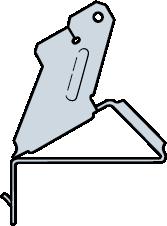
Simpson Strong-Tie VPA Connector
Wedge or Tapered Plate
Edges to be fixed down to the support without any splitting. Tie-down the rafters directly to supports
To Support 8x 75x3.75 Nails Uplift Dead 1.58 kN 2.88 kN
To Supported Member 2x 40x3.75 Nails
Simpson Strong-Tie VPA connector with additional tie-down to rafters as required. 1.58 kN maximum tiedown supplied by VPA connector.
Capacities shown apply to the VPA being fixed to a plate with a minimum joint group of JD4 using all connections as indicated in the table above.
Installation of VPA Connectors
Flange
Flange
Step 1: Install top and face 3.75x75 nails in the “A” flange to outside wall top plate
Step 2: Seat rafter with a hammer, adjusting the “B” flange to the required pitch
Step 4: Install 3.75x30 nails into face of rafter both sides
Refer to page 33 for specification notes
Step 3: Install “B” flange 3.75x75 nails in the round nail holes, locking the pitch
Refer to page 50 for specification notes
Refer to page 50 for specification notes
ROOF RAFTERS
ROOF BEAMs
Roof Beams are members designed to support Rafters. Rafters may be supported by butting into the face of Roof Beams or supported over Roof Beams. Roof Beams can be designed to transfer either just roof or roof and ceiling loads supported by the rafters.
Care should be taken to ensure the correct supports are applied to each Roof Beam support and that sufficient tie-downs have been applied. Refer to Australian Standard AS1684 for more information.
Refer to page 50 for specification notes
ROOF BEAM
ROOF BEAM
ROOF BEAM
ROOF BEAM
Ceiling Joist
Counter Beam
CEILING JOISTS
CeilingJoistSpan
CeilingJoistSpan
Hanging Beam
Ceiling Joists are members which support the ceiling lining only. Ceiling Joist spacing shall be governed by the maximum allowable span of the supported ceiling lining.
Ceiling Joists may free span between internal supports or be supported intermediately by Hanging Beams (see page 29). Ceiling Joists are to be fixed to Hanging Beams via either 35x32mm timber cleats / droppers with 2/ 75x3.15 framing nails to each member, 25x1.6mm galvanized strap, ceiling joist hangers or Simpson Strong-Tie TCP clips.
CEILING JOISTS
Refer to page 50 for specification notes
HANGING BEAMS
Ceiling Joist
Counter Beam
Beam
Block
Hanging Beams are designed to support loads transferred via the ceiling joists only. Hanging Beams are generally positioned perpendicular to the Ceiling Joists which are then hung from the underside of the member.
Where Hanging Beams are supported by external walls which also support Rafters; provisions are required to the end of the member to prevent extrusion through the roof covering. A pre-manufactured Splayed Beam or Jack Trimmer Joist will be required.
Support of Hanging Beam with Jack Trimmer Joist
Timber Cleat fixed to with 2/75x3.15 Nails to both Hanging Beam and Block
Block the same depth as Ceiling Joists and same width as Hanging Beam
2x M10 Bolts through Hanging Beam and paired rafter
Hanging
Ceiling Joist
Rafter
HANGING BEAMS
COUNTER BEAMS
Ceiling Joist
Block
CounterBeamSpan
Counter Beams run parallel to Ceiling Joists and are design to support Hanging Beams. The supported Hanging Beam will be supporting underlying ceiling joists. The spans published for Counter Beams have been determined by supporting the Hanging Beam in the worst case scenario.
Counter Beams support ceiling loads only. Where a point load is applied by a roof strut onto either the Counter Beam or the Hanging Beam these must be designed as a Counter Strutting Beam or Hanging Strutting Beam respectively.
Determining Ceiling Area supported by Counter Beam
Support to Counter Beam
Counter Beam
Hanging Beams supporting Ceiling Joists
Ceiling Joists
Support to Counter Beam
Supported Ceiling Area
HangingBeamSpan
Recommended Hanging Beam to Counter Beam Connection
Refer to page 50 for specification notes
Joist Hanger
LINTELS
Lintels are beams positioned in a wall frame designed to span across a window or door opening to support roof and/or floor loads above. Lintels are supported by Jamb Studs.
Lintel Span
Lintel Supporting Jamb Studs
Span
Single / Upper Lintel Jamb Studs
Lower Level Lintel Jamb Studs
SINGLE / UPPER LEVEL LINTELS
SINGLE
Guide Notes - General
1. Refer to pages 8 and 9 of this guide for span and span type definitions
2. Member sizes specified based on serviceability criteria outlined in the tables in AS170.3 Section 2
3. Member sizes nominated are based on the product being fully protected from moisture and maintains an average moisture content of 15% or less over a period of 12 months i.e. K4 = 1.0 per AS1720.1 clause 2.4.2.3.
4. Member sizes nominated are based on construction in coastal areas south of latitude 250 and south of latitude 160 in all other areas i.e. k6 = 1.0 per AS1720.1 clause 2.4.3
5. Bearer sizes and spans are subject to minimum bearing requirements shown on Page 14.
6. Spec Beam® LVL may be cut, drilled, or notched using standard woodworking tools, subject to the limitations outlined in this guide. All cutting and drilling must comply with the hole and notch limits provided.
7. All fixings must be compatible with timber construction and suitable for the exposure conditions of the application. Corrosion protection must comply with the requirements of the relevant Australian Standards.
Guide Notes - Floor Framing
8. Floor joist centres should be selected as such to obtain adequate support for flooring / floor sheeting
9. Refer to page 9 for common floor covering types and their required supporting joist centres
10. Floor framing members are to be installed per AS1684.2, AS1684.3 and good building practice
11. Flooring to be installed per AS1684.2 and AS1684.3. Particle board flooring to be installed per AS1860.2
12. Floor Bearers designed as Category 2 Primary Elements per Table 2.1 of AS1720.1
13. Floor Trimmer / Bearer details shown are based on the floor joists supported continuously over
14. Where members are supporting roof loads an N3 wind load has been applied
Guide Notes - Roof & Wall Framing
15. All members are designed using a wind speed category of N3
16. Rafter and Ceiling joist spacings / centres should be selected as such to obtain adequate support for Roof batten or Ceiling Material respectively. Refer to product manufacturer for details
17. Refer to page 30 for common roof covering types and their weights
18. Roof framing members to be installed per AS1684.2 and good building practice
19. Beam details shown are based on the Rafter being supported continuously over
20. Lower Level Lintels are designed as Category 2 Primary Elements per Table 2.1 of AS1720.1
21. Single Upper Level Lintels to be supported on Jamb Studs a minumum of 45mm wide
22. Lower Level Litnels to be supported on Jamb Studs a minimum of 90mm wide
Design Responsibility
This guide provides span and sizing information for common residential applications only. It does not replace project-specific engineering design.
Where conditions fall outside the scope of this guide, including but not limited to:
• Non-standard loading conditions
• Commercial or industrial applications
• Irregular framing layouts
Design must be undertaken by a suitably qualified structural engineer.
Information in the guide is to be used for ITI Spec Beam 13.2 LVL only This guide must must be used for ITI Spec Beam Green 13.2 LVL H3 Treated
Product Handling & Storage
Spec Beam® 13.2 LVL should be stored flat, off the ground, and protected from weather exposure prior to installation. Temporary exposure during construction is acceptable; however, prolonged exposure to moisture should be avoided.
Transport
While transporting or storing the product, increased moisture caused by rain or splashing must be avoided. If Spec Beam products are moved with a forklift truck, wide enough forks must be used in order to avoid damaging the product. When lifting several packs at a time, the distance between forks must be wide enough to ensure safe lifting. Surface-treated products should be delivered direct to site without additional, unnecessary off-loading during delivery.
Storage
Spec Beam products must be stored under cover. When storing the products temporarily on site, a solid, straight and dry platform should be used. The height of ground bearers must be at least 300 mm. To avoid twisting of the product, the bearers between packs must be aligned vertically with the ground bearing timbers.
The plastic wrapping of each pack must be cut open from underneath to enable moisture to evaporate from the bundles. If the products are stored on site for longer than one week, the bundles must be covered with an additional protective covering. Conditions of the products and protective cover must be monitored regularly during storage.
Handling
Spec Beam product packs may be unloaded on site with either a forklift or a crane. Approved webbing slings must be used if unloading with crane. It is forbidden to use chains or wires.
If unloading is done manually, the pack is opened and the products are carried one-by-one. While cutting the banding, beware of band’s ends. Spec Beam products should not be dragged or dropped.
Spec Beam is a light-weight material and is easy to shape, which means notable time and cost savings in construction. Spec Beam products can be processed with conventional wood working and power tools. There is no need for separate specialist tools.
Product Identification
Each Spec Beam® 13.2 LVL member is clearly marked with:
• Product name
• Strength grade
• Joint group classification
• Manufacturing information
This identification provides traceability and confirms compliance with applicable standards.
Disclaimer
This document has been prepared as a technical guide to assist designers, builders, and industry professionals. While every effort has been made to ensure accuracy, ITI does not accept liability for errors or omissions arising from reliance on this guide.
Users must ensure that all designs and installations comply with current building regulations, standards, and project-specific requirements.
Simpson Strong-Tie is one of the largest suppliers of structural building products in the world, including timber connectors, fasteners, fastening systems, anchors and lateral-force resisting systems. The company is known for its commitment to product development, engineering, testing and training as well as providing customers with quality products and exceptional service. Today, Simpson Strong-Tie has more than 3,100 employees and more than 50 factories, offices and warehouses all around the globe.
Simpson Strong-Tie began manufacturing engineered structural connectors for timber-framed construction in 1956 in California, USA. Nearly 40 years later, the company entered the anchoring industry, and the product line has expanded to include many anchoring, crack-injection repair and masonry adhesives, and a full line of powder-actuated tools and fasteners.
Dunnings understands the needs of truss and trade businesses. Through experience, expertise and local manufacturing capability, Dunnings supply products that meet or exceed all relevant Australian standards.
Dunnings engineering capability is fully supported by a large in-house Australian engineering team. Dunnings supply the fixing and load capacities for their whole range of timber connectors and builders’ hardware through their Engineering Data Book.
Manufacturing since 1951, the business is Australian owned and operated and continues to manufacture here in Australia.
We offer a comprehensive range of Australian-made timber connectors and builders hardware, as well as products sourced globally.
1. Hangers to be a minimum of 2/3 the depth of the I-Joists.
2. Nails are required to be installed to all pre-determined holes in I-Joist hangers.
3. Minimum of 65x3.75mm nails to be used into the supported member use using LUS type hangers
4. Refer to ITI Spec Sheet 2 for product capacities
Simpson Strong-Tie Beam to Beam Hangers
Dunnings Beam to Beam Hangers
Dunnings Cleats
ITI Australia has a reputation of providing customers with a diverse range of products. By stocking a wide range of structural, outdoor and decorative building products ITI can add value without overheads to our loyal customer base. Some other products on offer include the following.
SPECFRAME 10.0
Spec Frame 10.0 is ITI’s engineered Laminated Veneer Lumber (LVL) alternative to MGP10. Make wall framing straight the first time and eliminate the need to sight your framing for bow, spring or twist. With a joint group of JD3, Spec Frame 10.0, provides superior fixing capacity for bracing components.
SPECFRAME 12.1
Spec Frame 12.1 is ITI’s engineered Laminated Veneer Lumber (LVL) alternative to MGP12. Make wall framing straight the first time and eliminate the need to sight your framing for bow, spring or twist. With a joint group of JD3, Spec Frame 12.1, provides superior fixing capacity for bracing components.
SPECFLOOR 12.1
Spec Floor 12.1 is ITI’s engineered Laminated Veneer Lumber (LVL) alternative to 4inch green hardwood sub floor bearers and joists in New South Wales. Additionally Spec Floor 12.1 is available in 300x45 in Victoria. Made from light weight plantation softwood it’s lightweight, straight and easy to cut.
SPECBEAM 14.5
Available in Tasmania & Victoria Spec Beam 14.5 is available in 45mm wide sections in the same depths as traditional F17 hardwood. Exceptional bending and strength properties allow you to safely substitute Spec Beam 14.5 for any E14 LVL and F17 Hardwood products in the same section size as well as 42mm LVL 15 grade in the same depths
SPECBEAM13.2GREEN
Each sheet of veneer used in the manufactering of Spec Beam Green is pre-treated to Hazard Class 3 for use in exposed and high moisture application prior to gluing and pressing making it treated to the core. Available in New South Wales and Queensland.
SPECJO ST
Available in New South Wales, Queensland & Western Australia, Spec Joists Wooden I-Joists are comprised of high grade LVL top & bottom flanges with as OSB web. The combination of these components creates an ideal timber joist with a 300mm deep option capable of spanning 6.0m. Spec Joists can be provided docked to length and with service holes pre-cut to save time on site - consult your local timber supplier for more details.
SPECLAM 15
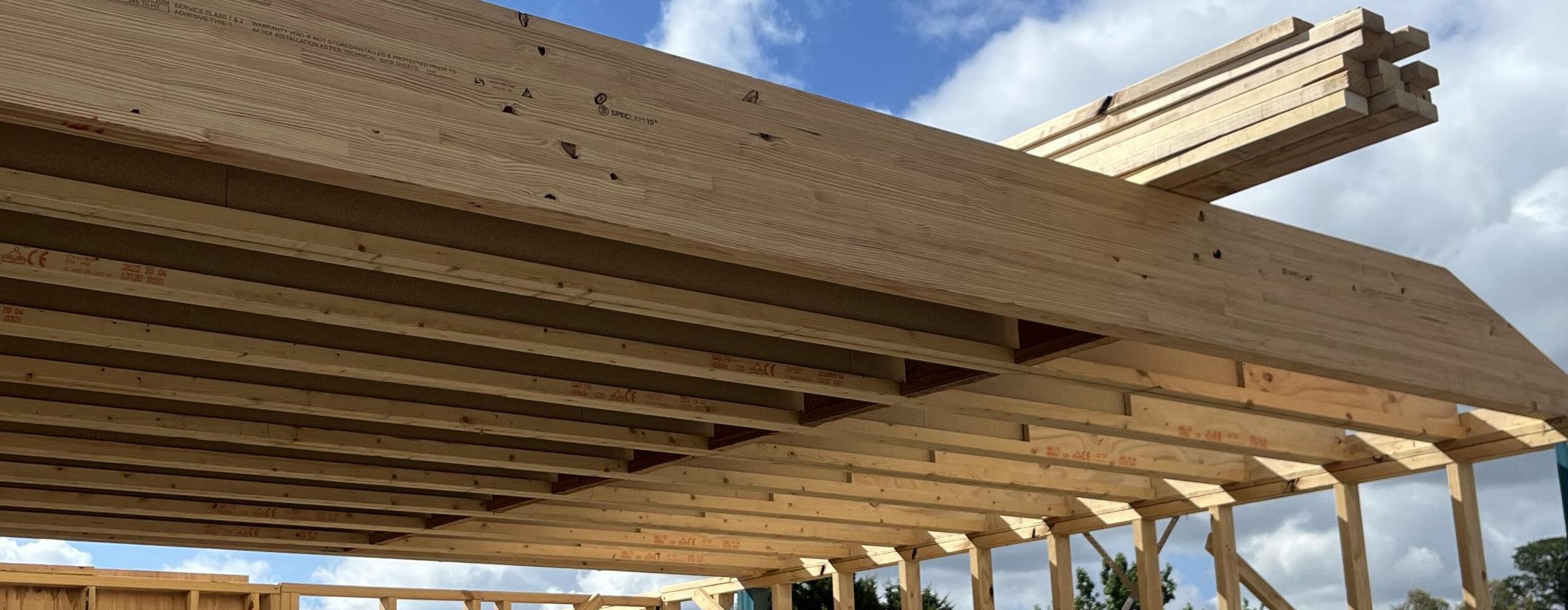
Spec Lam 15+ is an Australian-manufactured structural glue-laminated beam product developed specifically to match the depth of ITI’s broader range of Laminated Veneer Lumber and Wooden I-Joist products, along with open-web trusses commonly used in floor framing systems. Spec Lam 15+ is a non-visual / structural grade replacement for GL17 timber glue laminated beams.
Form Spec LVL is either lightweight New Zealand Radiata Pine or European Spruce designed specifically for concrete soffit forming. Weighing as much as 25% less than other products available in Australia, Form Spec LVL is ideally suited for the agile process of form working.
Edge Spec is a concrete edge forming laminated veneer lumber board designed to resist deformation generated by uneven uptake of moisture which occurs during the concrete pouring process. It boasts high quality veneers to the outer faces for a clean finish and small pencil round corners for ease of handling.
Design Link: An eco-system of design, technology, and processing
ITI Australia’s service offer surpasses providing quality, conforming building materials. With the ongoing implementation of complimenting technology, ITI can provide building professionals with a plan’s to site building solution for structural timber floor and roof systems.
ITI’s Structural Design & Specification Service
ITI Australia offer a free design, re-specification and take-off service for anyone who intends on building with ITI’s range engineered wood products incorporated in this guide. Our Design & Specification offer covers:
Floor Framing, Pitched Skillion or Gable Roof Framing using ITI’s range of I-Joists, Laminated Veneer Lumber (LVL) and Glue Laminated Timber Beams (GLT).
Particleboard Flooring and Wet Area Flooring using a stock ITI sheet product such as OxyMag or James Hardie Secura Flooring.
Balconies and Decks attached to an ITI designed First Floor using treated pine, Flame Fixx, Design Pine or any other ITI structural products.
Less Time. Less Waste. Less Mistakes. More Profit
Internal engineering support: ITI Australia understands our products better than anyone. With deep knowledge of product strengths and performance, our internal engineering experts deliver bespoke solutions for improved on-site construction outcomes.
Bill of Materials CSV Files: Provide ITI with your preferred CSV or spreadsheet format, and we will tailor a bill of materials report to meet your requirements and streamline your data entry process.
IFC & DWG data file sharing: Get all fabrication-based trades and suppliers on the same page. By sharing IFC 3D modeling files, all trades can understand their place within the overall structure, eliminating costly mistakes caused by setout height errors.
Showroom 3D Models: Showroom 3D models provide an interactive way to explore ITI’s specifications and installation details before arriving on-site. Life-size model walkthroughs are also possible using a Virtual Reality headset.
ITI LOCATIONS:
ITI Technical Support Centre
68-80 Kirkham Road West, Keysborough, Victoria 3173
E || ewp@iti.net.au
P || 03 9392 8400
ITI New South Wales (Sydney) 59 Dunheved Circuit, St Marys, New South Wales 2760
P || 02 8805 5000
E || ewpnsw@iti.net.au
ITI New South Wales (Newcastle) 19 Nelson Road, Cardiff, New South Wales 2285
P || 02 4953 7666
E || ewpnsw@iti.net.au
ITI Queensland (Brisbane) 63 Creek Street, Bundamba, Queensland 4034
P || 07 3436 8400
E || ewpqld@iti.net.au
ITI Queensland (Townsville) 54-62 Enterprise Street Bohle, Queensland 4818
P || 07 4724 5509
E || ewpqld@iti.net.au
ITI South Australia (Adelaide) 82-94 Grand Trunkway, Gillman, South Australia 5013
P || 08 8447 0400
E || ewpsa@iti.net.au
ITI Victoria (Melbourne) 68-80 Kirkham Road West, Keysborough, Victoria 3173
E || ewpvic@iti.net.au
P || 03 9392 8400
ITI Western Australia (Perth) 102-108 Bannister Road, Canning Vale, Western Australia 6155
P || 08 9256 5700
E || ewpwa@iti.net.au
ITI TASMANIA (BELL BAY) 17 Bell Bay Road, Bell Bay, Tasmaina 7253