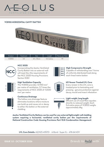
VCB1S5 HORIZONTAL CAVITY BATTEN
Product
Treatment
Size
Length
Pieces per Pack
VCB1S5
H3
65 x 35mm
5.4 metres
99
NCC 2025 Incorporating the Aeolus Ventilated Cavity Batten into an external wall will meet the rthe requirements of the NCC 2025 Housing Provisions Section 10.8.1
High Compressive Strength Capable of withstanding over 1 tonne of uniformly distributed load along each lineal metre batten
High Ventilation Capacity The VCB1S5 provides >3,700 mm2 per metre of ventilation. 3.7 times the requirements of NCC 2025 of >1,000 mm2 per metre
H3 Veneer Treated LVL Core Every veneer in the LVL core is treated prior to laminating and pressing - genuine protection against decay, mould and insect infestation
Continuous Drainage The hollow core drainage feature eliminates locations where moisture can build up and cause rot or decay to either the batten or the external cladding
Light weight, long length Efficient use of wood fibre equates directly to reduced weight. Each 5.4 metre piece of VCB1S5 weighs approximately 6kg
Aeolus Ventilated Cavity Battens can be used for any external lightweight wall cladding system requiring a horizontal, ventilated cavity batten per the requirements of National Construction Code Housing Provisions Part 10.8 Condensation Management
LVL Core Details: AS/NZS 4357.0 - A-Bond - Super E0 - 476 64 H3V
ISSUE 1.0 - OCTOBER 2026
Detail 1 - Batten Fall Direction
Install with the slope directing moisture outwards, towards the cladding face
A up ng faci text e front all Inst is is th Th
A
Detail 2 - Fixing Penetration
Fixings to penetrate through outer hollow core structure
Detail 3 - Cladding to Batten Fixings
Minimum length of fixing penetrating into cavity batten: 10x fixing thickness + 5mm
up ng faci text e front all Inst is is th Th
Detail 4 - External Corner Detail
B
Cladding Corner Detail Min. 2mm Control Gap Aeolus Cavity Batten Wall Framing up ng faci text e front all Inst is is th Th
Detail 5 - Internal Corner Detail
B
Wall Framing Min. 2mm Control Gap Cladding Corner Detail Aeolus Cavity Batten up ng faci text e front all Inst is is th Th
B
Detail 6 - Batten Cantilever A (Table Below)
A/3
Maximum cantilever equals designed wall stud spacings divided by 3
35mm Cavity Closer or fire protection as required by others
Max. Wind Classification
B - Max. Batten Spacing
N2
900mm
N3
C2 C3
A - Maximum Stud Spacings Timber Framing - JD5 minimum 450mm
600mm
2 / 3.15x75mm Nails or
2 / 3.15x75mm Nails or
1 / 10gx60mm Screws
1 / 10gx60mm Screws
2 / 3.15x75mm Nails or
2 / 3.15x75mm Nails or
1 / 10gx60mm Screws
1 / 10gx60mm Screws
900mm
1 / 10gx60mm Screws
1 / 10gx60mm Screws
450mm
Steel Framing - 0.75BMT minimum 450mm
600mm
1 / 10gx45mm Screw
1 / 10gx45mm Screw
1 / 10gx45mm Screw
1 / 10gx45mm Screw
1 / 10gx45mm Screws
2 / 10gx45mm Screws
450mm
1 / 10gx60mm Screws
1 / 10gx60mm Screws
1 / 10gx45mm Screws
2 / 10gx45mm Screws
900mm
1 / 10gx60mm Screws
2 / 10gx60mm Screws
2 / 10gx45mm Screws
2 / 14gx45mm Screws
450mm
1 / 10gx60mm Screws
2 / 10gx60mm Screws
1 / 14gx45mm Screws
2 / 14gx45mm Screws
ISSUE 1.0 - OCTOBER 2026