







This handbook consists of two volumes which describe the ITER design from its inception up to the design, construction and assembly in 2025.
The handbook is not designed to be read as a continuous sequence of chapters. Instead, it is composed of focused, self-contained sections that address specific topics. Each chapter can be read and understood independently, allowing readers to engage with the material most relevant to their needs without requiring familiarity with preceding chapters. As a result, the reader will find certain overlapping content in chapters.
It is to be noted that at the time of writing, the design for some systems is still on-going. Therefore, the reader should consider that whilst there is significant value of this important point-in-time study, an update would be required as the Project progresses
A broad Project overview is given in the first volume, to provide the reader with background information necessary to understand the context in the subsequent moredetailed chapters of the second volume, dedicated to the individual systems composing ITER.
For the overall table of contents of the Handbook and to access each one of the chapters, please refer to htps://www.iter.org/scien�sts/iter-technical-reports/iter-engineeringbasis-handbook
This chapter is authored by Gianfranco Federici and co-authored by the Handbook Editors Federico Casci, Stefano Chiocchio, Richard Hawryluk, John How, Juan Knaster, Akko Maas, Masanori Onozuka, René Raffray, Gabriella Saibene, Bill Spears and Eisuke Tada
Fusion power offers the prospect of an almost inexhaustible source of energy for future generations. However, it is not there yet, and harnessing fusion energy and deploying reliable fusion power plants relies on the ability to overcome the remaining design, physics and engineering gaps and development needs for key fusion technologies that are essential for reliable and efficient operation of a fusion reactor. The design and R&D of future fusion reactor concepts is expected to benefit from the experience gained in the design, licensing, construction and operation of ITER.
There are still significant differences of opinion around the world, even within the ITER Members, on how to bridge the gaps between ITER and a future fusion power plant. Nevertheless, there are outstanding issues common to subsequent major facilities after ITER, whether a component test facility [1], a Pilot Plant [2], a Demonstration Plant (DEMO) [3], or other. Depending on the confinement scheme and fuels postulated, these include the need to develop foreseeable sound technical solutions for crucial problems. For example, in the case of Magnetic Fusion Energy (MFE) such problems include plasma heating and power exhaust, tritium breeding and fuel cycle, cooling and extraction of high-grade heat from the breeding blanket, remote maintenance for the invessel components, robust magnet designs, qualified structural and plasma facing materials and nuclear safety.
Future fusion reactors, either with magnetic- or inertial confinement, will be affected by a high degree of complexity and system interdependencies and their optimised performance will depend on multiple design drivers across various systems. The integration of technologies into a coherent
design is a central challenge for fusion, and delaying it leads to a high risk that solutions developed would not reflect an adequately integrated design, putting at risk the ensuing assembly and operation. The perspective on fusion research and the importance of ITER is also described in Ref. [P. Barabaschi and the ITER Team, Progress of iter and its importance for fusion development, to appear in Nuclear Fusion 2026]
The commercialisation of fusion energy still carries uncertainties and depends on solving a number of overarching scientific and technological challenges. Despite the uncertainties remaining on the timeline for the realisation of fusion energy demonstration plants (i.e., next step after ITER for MFE), several teams worldwide are designing fusion power plants. MFE-based concepts are the most mature of these designs with the DEMO programme underway in Europe [3],[4] , the Chinese Fusion Engineering Test Reactor (CFETR) programme in China [5], the Spherical Tokamak for Energy Production (STEP) programme [6] in the UK, and other initiatives in Japan, South Korea, Russia and the US. Major Inertial Fusion Energy (IFE) Concepts have also been pursued in the past, most notably the effort on Laser Inertial Fusion Energy (LIFE) Engine [7], [8] and on fusion energy with lasers and direct drive targets [9] in the US. Newer IFE efforts [10], [11], [12] are also emerging following the important results achieved in the National Ignition Facility [13]. A recent review of fusion projects with a commercial ambition can be found elsewhere [14]
Despite the clear differences in approach between IFE and MFE, and the widening of the fusion portfolio, there remains a degree of commonality both in the driving issues for the design of power plants and the technical challenges they face. This is not to say that at the detailed technological level there is significant overlap between approaches, but it highlights that within these different approaches, there are some overarching challenges where commonality may be exploited
This chapter addresses the commonalities between MFE and IFE for harnessing fusion energy. The main lessons learned from the design, construction and operation of fusion devices such as the Joint European Torus (JET), NIF and some similarities with the design of advanced fission energy systems are then summarised. The prospects of alternative magnetic configurations, like stellarators, spherical tokamaks (ST), and alternative fuels and inertial confinement fusion systems are briefly looked at, with respect to the remaining critical issues for fusion power plant designs.
Common issues and technology challenges are discussed with emphasis on the low readiness of some enabling core fusion technologies. Two important examples are discussed: the breeding and recovery of tritium fuel to close the fuel cycle, and the reliability and maintainability of critical core components (fusion nuclear technologies). Some risk mitigation strategies are discussed. Finally, some considerations are given on the prospects, risks and challenges arising from fusion regulation uncertainties, skill gaps and work force development, involvement of industry and the establishment of resilient supply chains, and the role of private investors including fusion startups.
In all magnetic and inertial fusion confinement approaches, a unifying first step feature is to achieve energy gain, whereby power production from fusion reactions is greater than the required heating power to sustain the process, or the energy released exceeds the initiating energy. The gain factor, Q, quantifies this with Q=1 representing the ‘breakeven’ state where power/energy used for heating the system is balanced by that produced by fusion (see Chapter 4). Such breakeven is a key threshold in the development of fusion energy but a more telling global measure is to consider the gain from the fusion energy compared to the energy demand of the whole plant (including the efficiency of the heating systems and other energy consumption).
A useful parameter for assessing the performance of a thermal fusion plasma towards producing gain is the fusion triple product, which balances plasma self-heating due to fusion against radiative cooling and other energy loss mechanisms. This criterion [15] provides a condition on the plasma density, n, temperature, T, and energy confinement time, τE, by evaluating the balance between fusion energy production and loss mechanisms. Collectively, these three parameters are termed the ‘fusion triple product’ and can be used to provide a simple condition for the state in which plasma self-heating may be sufficient to sustain the reaction:
for the fusion deuterium-tritium (DT) reaction in the temperature range 10–20 keV. This is true for all approaches to thermal plasma DT fusion and serves to differentiate them by the way in which this criterion is satisfied.
In MFE [16], the focus is placed on maximising the energy confinement time. This is achieved by using strong magnetic fields to confine a plasma in a fixed volume for long times during which heating is applied to achieve fusion conditions. The most mature MFE concept is the tokamak [17] where a helical magnetic field is created in a torus through a combination of externally applied fields, and fields induced by currents driven within the plasma itself. The Joint European Torus (JET) holds the world record for fusion yield. In 1997, JET achieved a fusion power of 16 MW for a power input of 24 MW (so a Q of 0.6) and in 2023, JET released 69 MJ of fusion energy over 5 seconds [18], but despite these records, JET could not reach high gain required for power production due to its size.
The next stage of tokamak development, ITER, will have a plasma volume 10 times that of JET and has been extensively discussed in this book. ITER targets a Q factor of 10 by generating around 500 MW of fusion power and will be a proving ground for many important technologies. While
this will be a major step forward in fusion energy development, ITER is not designed to produce more energy than used by the entire plant nor to produce electricity.
Other magnetic confinement approaches to fusion exist alongside tokamaks with varying degrees of maturity. Notable among them is the stellarator [19] where a helical magnetic field is once again produced in a torus, but in contrast to the tokamak, this is produced entirely via external fields. This brings the advantage of offering true steady-state operation. A tokamak, by contrast, requires the ramping of a voltage in its central solenoid to induce a plasma current which would necessitate short breaks in operation to reset if the current could not be sustained non-inductively in an effective way. The steady-state operation of a stellarator comes at the cost of engineering complexity but has the potential of avoiding abrupt plasma terminations (disruptions), which affect the design of tokamak components. The critical engineering issues associated with the stellarators and spherical tokamaks are briefly discussed in section 9 4 In IFE [20], [21], the motion of the plasma is normally not constrained by magnetic fields (though there are concepts put forward, where magnetic fields are key components to IFE [22]). In IFE, the confinement time may be governed by different mechanisms depending on how the specific IFE scheme is designed; however, in all cases, this is many orders of magnitude lower than in the MFE case. Instead, the approach relies on achieving high densities, for example, by focussing high-energy lasers on a small cryogenic fuel capsule, whereby the ablation of the capsule surface drives an implosion of the fuel via rocket action.
As the fuel implodes, the core is heated to fusion conditions and the high density from compression provides the conditions necessary for the fuel to ignite. The National Ignition Facility (NIF) [23] together with the Laser Megajoule (LMJ) [24] are the largest existing IFE facilities in the world.
In 2022, the NIF demonstrated target gain with more fusion energy released (3 MJ) than delivered to the target [25] (2 MJ). Further experiments in February 2024 yielded 5.2 MJ of output from 2.2 MJ of input, and an experiment in April 2025 achieved a yield of 8.6 MJ. The implications of these results and the challenges remaining are briefly discussed in sections 9.3 and 9.7 respectively.
The record-breaking results from JET and NIF challenged the perception that controlled fusion energy is out of reach. In both cases, the gap from their largest predecessor facility was huge, with considerable uncertainties in the physics understanding upon which the machine specifications were predicated [26]. It is also true that neither JET nor NIF reached their goals immediately, and that they have been successfully operated and their performance substantially improved through significant design modifications and machine upgrades throughout their lifetimes.
With careful and periodical maintenance and enhancement, the complex JET facility was in operation more than four decades and is a good example of where a staged operational approach has been applied. Substantial increases in auxiliary power, an internal poloidal divertor, significant remote handling capability and change of the first wall and divertor materials have been implemented at various points during JET’s operational lifetime.
Fortunately, JET was designed with sufficient flexibility to prepare for the envisaged and not envisaged upgrade paths and, notably, the inclusion of D-shape TF coils in the original design proved to be a key design decision that allowed the subsequent inclusion of a divertor. In addition, remote handling (RH) tools were developed in JET from the beginning, well in advance of DT operations, and have been instrumental in the refurbishment/repair of components in conditions where machine access was very limited.
In the case of NIF, results from experiments on precursor laser facilities, such as the Nova laser facility at the Lawrence Livermore National Laboratory, and simulations of ignition target designs, pointed to the need to design NIF to deliver 60 times more energy across nearly 20 times more beamlines than Nova, an enormous scale-up of complexity that would require numerous technologies to be invented. Innovations included new techniques for fabricating the glass for NIF’s 192 laser beams and means to rapidly grow the high-purity KDP crystals that were needed to convert laser to higher frequency. In addition, a novel method was invented to rapidly and cleanly switch the laser beams into and out of the amplifier chain. In time, NIF1 met all of the challenging performance goals specified when it was designed and began operations in 2009. It did eventually reach ignition through a deliberate process of devising innovations to overcome identified hurdles.
Progress was needed on many fronts. Development of effective means to mitigate damage to laser glass enabled NIF to operate at higher energy and power levels. Target designs were refined through a combination of enhanced physics simulations on more powerful computers and vastly improved experimental diagnostics. This included choosing the optimum hohlraum trading off several aspects including laser-plasma interactions, hohlraum energetics, capsule performance, laser performance, drive asymmetry. In addition, techniques for manufacturing targets were developed to make the highly precise cryogenically cooled targets needed to achieve ignition.
While these considerations in terms of flexibility and staged operation are very important, extrapolation to the next generation of fusion reactors for both MFE and IFE with the notion of progressive learning and machine adaptation and refurbishment, requires some caution. Work in
1 Since 2008, U.S. researchers at the National Ignition Facility (NIF) at Lawrence Livermore National Laboratory have been supporting national security by conducting experiments with powerful lasers, using inertial confinement approaches, to enhance nuclear weapon stockpile stewardship and some basic fusion science. Stockpile stewardship includes science-based assessment of the reliability of nuclear weapons to assess and certify the stockpile without nuclear explosive testing.
Europe [28] addresses, at least preliminarily, the problem of designing and operating a future fusion power plant with a “staged operation” approach. The need to include sufficient flexibility in the design of EU-DEMO to accommodate improvements in plasma performance and design improvements of core components is generally supported.
However, for a nuclear fusion reactor (for example, the EU-DEMO, and even for ITER), this flexibility is limited, and it is not currently clear to what extent this can be achieved due to many interrelated aspects that affect design margins, safe operation and maintenance, regulatory conformance and machine performance. The benefits of adopting a flexible design approach are illustrated in
Figure 9 1, where a planned progressive evolution of the system (i.e. from Period 1 to Period 2 and beyond) provides a mechanism for increasing the performance of a particular function or functions over the course of the operational life.
It also provides the opportunity to close possible performance gaps with respect to the target performance levels and provides greater flexibility in agreeing system requirements. An initial analysis [28] of the potential upgrade paths for EU-DEMO is provided elsewhere. Whilst certainly not exhaustive, this analysis shows that there are interrelated aspects, and it will be necessary to investigate how this embedded flexibility affects other system attributes such as performance, safety, risk and cost. A key element of such an analysis is the capability of remote handling to replace highly activated and contaminated components in a timely manner.
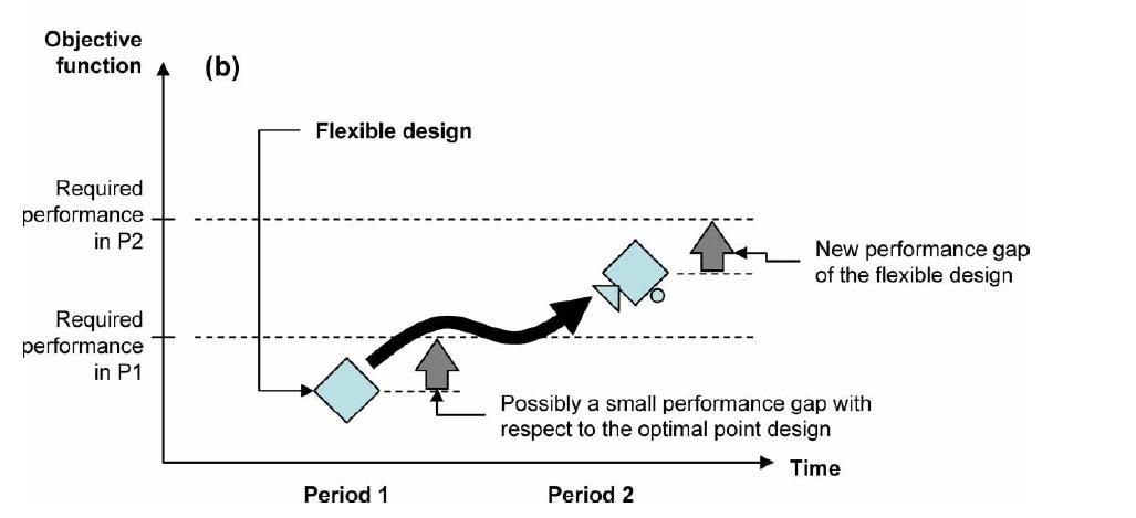
9 1 Staged approach through flexible design [137]
However, it should be noted that it is much more difficult to adapt a highly irradiated machine than previous experiments, and these limitations have to be considered in the design phases. One should for instance not expect to make major upgrades to the final physics performance by installing new equipment, and one should have the objective of simplifying and optimising things like diagnostics once one can infer what is going on, so that they interfere less with reliable
operation. Consideration of the impact that upgrades may have on established interfaces must be given great attention, e.g. the blanket remote maintenance tooling and procedures will be designed to suit a particular configuration of cooling pipes, structural attachments and other service connections. For example, it would not be possible to increase the breeding blanket operating temperature to increase the thermodynamic efficiency and the net electrical power output by installing a second set of breeding blankets made of high-performance steels. Due to an increase in temperature, this would require major upgrades of Primary Heat Transfer System and Balance of Plant System, which are unlikely to be feasible. Likewise, it will be impossible to achieve a higher blanket operating temperature by changing coolant i.e. water to helium as the coolant choice determines so much of the plant architecture (blanket design, pumps, HEXs, pipes, valves, etc.) that changing it would be completely unfeasible.
It will not be possible to increase the pulse duration by increasing for the flux swing of the central solenoid and upgrading it would be a major dismantling exercise in a nuclear environment. Nevertheless, one could think of a “progressive” approach by starting with a less optimised thermo-hydraulic or mechanics design (larger safety margin) of some of the internal replaceable components to cope with large uncertainties in the overall reactor loadings and performances.
In addition, it may be decided to deploy more efficient and performing solutions for diagnostics and auxiliary H&CD systems like Electron Cyclotron (EC) or Ion Cyclotron (IC) heating systems designed to operate into replaceable port plugs. The latter would enable extending the purely inductive pulse duration and potentially improve the plant efficiency. The benefit in this case could be, for example, an extension of the service life of in-vessel components through a reduction of the number of thermal cycles – because of an increase of pulse duration.
Other lessons learned when designing future energy systems, confirmed and amplified by the ITER experience, are the challenges linked with the complexities of the design, the integration of a large number of critical systems that have many interdependences, the overall plant performance and availability, the uncertainties of some of the underlying physics and technology assumptions, and the qualification, fabrication, assembly of first-of-a-kind (FOAK) fusion nuclear technologies. These are summarised below mostly with a focus on the MFE context.
Integration challenges- the design of ITER and indeed, of any future fusion reactor, is affected by a high degree of complexity and system interdependence and multiple design drivers across various systems that impact the design and performance of the plant. For instance, the choice of the coolant affects the overall design layout of the plant, and has a strong impact on design integration, maintenance, and safety due to the interfaces with all key nuclear systems. Safety, including radiation shielding, plays a major role in the design process, and an early engagement with licensing regulators is essential to understand and tackle licensing requirements through design.
Design dealing with uncertainties in physics and technology- A variety of fusion power plant system MFE and IFE designs have been studied in the past across the world [29], but the underlying physics and technology assumptions were found to be at an early stage of readiness. New designs must ensure that there is full compatibility between the physics and technology. The choice of the underlying assumptions made on some important physics parameters, such as density, confinement scaling law, beta, power and particle exhaust have profound implications on the size and cost of the device. System codes are used to determine machine parameters. These are programmes that attempt to model an entire fusion power plant self-consistently subject to physics and technological constraints.
The results should therefore represent a preliminary assessment of a realistic and achievable power plant - subject to the validity of the underlying assumptions. Sensitivity to these assumptions and constraints can be tested using a system code to, for example, compare the effects of an improvement in plasma energy confinement on the final plant design, or to show the consequences of having to limit heat transfer to the divertor to match the constraints on the high heat-flux materials. Establishing performance requirements and realistic project development schedules is expected to be a strong driver in the selection of the technical features of the device, possibly favouring more conservative technology choices for near-term solutions.
The development of an advanced design which incorporates significant changes in comparison with existing practice would require more R&D, feasibility tests, and the willingness to take a higher risk. As most components or materials that are used in ITER are not fully reactor relevant, further developments beyond ITER are needed and will stem from imperative design drivers that cannot be compromised by lack of representative operating data. The impact on the overall plant safety, reliability and availability of the various system design options must therefore be analysed in an integrated approach, with development testing and qualification programmes developed accordingly.
Qualification, fabrication, assembly of FOAK fusion nuclear technology – Because most of the high-tech systems and components of a fusion reactor are not commercially available, their development can require long and expensive research, development, qualification and demonstration programmes with high risk of failure. This book has shed light on the intensive efforts taken to validate all specific technologies adopted by ITER, and the risks that, nonetheless, have emerged during the fabrication and assembly of some of the critical components.
Lessons learned from fission- To make sound choices concerning the future path of fusion power, one should draw important lessons from the fission experience of developing and deploying reactor plants through successive generations. The fission evolution has been catalysed by the need for advances in safety, materials, technology and commercial attractiveness in addition to strong involvement of industry from the beginning.
Different types of new nuclear plants are being developed today that are generally called advanced reactors. In general, an advanced plant design is a design of current interest for which improvement over its predecessors and/or existing designs is expected. Advanced reactors consist of evolutionary designs2 and innovative designs3, the latter including Small Modular Reactors (SMR) requiring substantial development efforts. Those are more ambitious and differ from evolutionary designs in that a prototype or a demonstration plant is required especially, to demonstrate the overall system integration of the plant. The paradigm used in fission for the justification and the definition of the top-level requirements of a demonstration prototype in fission are described in table 9.1 [32]
Table 9.1. Key requirements driving the design goal of a prototype in fission
Safety Safety analysis of the prototype should be as similar as possible to the safety analysis of the commercial plant.
Safety and design methodologies (including the simulation/analysis codes) shall be validated.
Adequacy of the safety requirements shall be also validated.
Design and technical solution
The adequacy of the design requirements to satisfy the plant operations and safety requirements shall be validated.
Then, those design requirements shall be propagated to the plant design, verified and validated, to finally demonstrate the system integration of the plant.
Technical solutions should be based on maintaining proven design features to minimise technological risks, but both highlighted the need to take risks when the reward is significant and there is a back-up plan.
The plant design should drive R&D and not the other way round
2 Evolutionary design - is an advanced design that achieves improvements over existing designs through small to moderate modifications, with a strong emphasis on maintaining proven design features to minimize technological risks. The development of an evolutionary design requires at most engineering and confirmatory testing.
3 Innovative design - is an advanced design which incorporates radical conceptual changes in design approaches or system configuration in comparison with existing practice. Substantial R&D, feasibility tests, and a prototype or demonstration plant are probably required.
Plant availability
Component lifetime
Inspectability/ maintainability
Reliability and maintainability should be key drivers: provide design margin (overdesign) where technology limits and budget will allow, since this will increase machine longevity, reliability and capability, when considering enhancements.
Prototype should reach high availability factors → This biases the selection for conservative solutions with high TRL (i.e., reliability) from the very beginning.
Component operation under nuclear conditions must demonstrate the potential to achieve lifetimes necessary for cost-efficient plant operation.
Prototype should be designed with demonstrated inspection and RH sequences.
In contrast to fission, where the benchmark design point is represented by existing operating plants (mostly Gen II) with very high availability, the only broadly representative fusion plant that will exist in the next thirty years is ITER.
Other magnetic confinement approaches to fusion exist alongside tokamaks at varying degrees of maturity. In this section, the most extensively studied, stellarators and spherical tokamaks will be discussed.
9.4.1 Stellarators
Notable among these alternative MCF configurations is the stellarator, relying once again on a helical magnetic field in a torus but, in contrast to the tokamak, produced entirely via external fields. This has the advantage of offering true steady-state operation, however, at the expense of increased engineering complexity. A tokamak, by contrast, requires the ramping of a voltage in its central solenoid to induce a plasma current, even if it can in principle be sustained non-inductively in steady state operation employing external current drive.
The experience gained with the construction and operation of Wendelstein 7-X [33] (W7-X, as illustrated in Fig. 9.2) in Germany has been extremely valuable and will impact future stellarator developments.
The goal of the project is to demonstrate the fusion reactor potential of optimised stellarators and to operate for the first time fusion-relevant plasmas under full steady-state conditions.
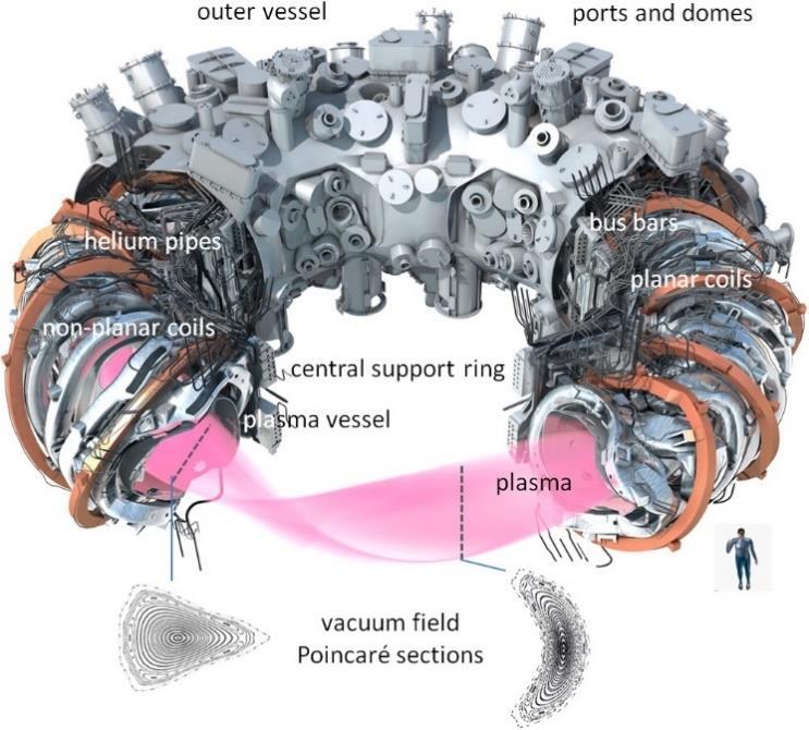
Fig. 9.2. Wendelstein 7-X with all its fittings and trimmings.
A 16-m wide container enclosing all the magnetic coils and their helium cooling liquid, with 250 access port
Since the early 1980s, several conceptual design studies of stellarator power plants have been performed in the USA [34], [35], [36], [37], Germany [38] and Japan [39]. A key breakthrough for modern stellarators has been the inception of (non-planar) modular coils [40] that provide much more freedom and flexibility in design compared to classical stellarators that rely on large helical coils. With the invention of modular coils, the W7-X design soon followed and was accompanied by corresponding reactor concept studies known as HELIAS [41].
Some effort was devoted to study compact stellarators comparable in size to advanced tokamaks to reduce capital costs, but this compactness was found to introduce complexity to all power core components, causing difficulties in fabrication, assembly, and maintenance. In recent years, there has been a renewed interest, triggered by private investors (see Section 9.10), to reconsider some of the options that were discarded in the past, or new approaches, on the basis of progress in plasma physics and technology. Stellarators are an area of active development and innovation worldwide (see for example [42], [43], [44], [45], [46], [47]).
Some of the specific critical engineering issues associated to this configuration include:
• Complexity of coil configuration and in-vessel component design - Modular, highly shaped, non-planar coils for stellarators can have quite complex geometries and result in a non-uniform coil bore and more complex in-vessel components. The non-planar coil incurs large bending forces that necessitate a more complex support structure to accommodate the loads. Large non-planar coil excursions can lead to interlocking coils that hamper assembly. New machine configurations have been developed that are compatible with sector maintenance of in-vessel systems and more conventional support structures [48]. The first wall (FW) and surrounding in-vessel components need to conform to the non-uniform plasma. Within each field period, the configuration changes from a bean-shape to a D-shape, and then back to a bean-shape (see Fig. 12.2.), continually switching the surfaces from convex to concave over a toroidal length of ~20 m. This means the FW and in-vessel component shapes vary toroidally and poloidally, representing challenges to 3D modelling, fabrication, design integration, and maintenance.
• Coil distance and shielding- An important aspect of stellarator coil design is the fact that there is a trade-off between coil shape complexity and plasma-coil distance. Generally, the non-planar coil excursions grow as the plasma-coil separation is increased. Therefore, for experiment scale stellarators, the coils are placed close to the plasma in order to reduce coil complexity. For a reactor-scale stellarator, the blanket and neutron shielding must fit between the plasma and coils, increasing the demand for plasma-coil separation, and consequently negatively impacting coil complexity. The plasma coil separation can be increased if the plasma and coils are scaled up together by the same factor, but this approach leads to large facilities. This was, for example, the case for the HELIAS-5 study because it conservatively reserved over 1.3 m space for the blanket. Any theoretical or numerical advances that lead to plasma shapes allowing for larger plasma-coil separation while retaining simpler shaped coils will have a significant impact on the design and size of future stellarator reactors. Consequently, this is an active area of research in the stellarator community. New computational tools have been developed to address the combined physics and technology requirements.
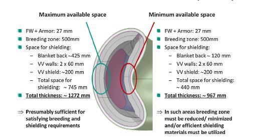
Fig.9.3. CAD model of a half field period of HELIAS 5-B showing maximum (outboard) and minimum (inboard) available space for breeding and shielding [49]
Divertor heat loads- similar to tokamaks, a large fraction of the plasma power should be radiated in order to limit the heat load on the stellarator divertor plates to below ~ 10MW/m2. Such detachment conditions have been realised in W7-X with stable conditions of nearly 10 minutes. These results seem encouraging for the energy exhaust, but at this moment the particle exhaust in W7-X lacks behind. As W7-X is an experiment, it features a flat, open divertor, which allows particles to escape both toroidally and poloidally, restricting the pressure that can be reached for effective pumping. Consequently, a reactor scale stellarator would likely need a closed divertor with baffling similar to tokamaks but is so far in the very early conceptual design phase. From the engineering side, it is important to accurately arrange and place the target elements in the 3D geometry to avoid leading edges and evenly distribute the heat. Besides careful tailoring of divertor plate shape and orientation to reduce the peaking factor, an optimised alignment of plates could lead to an acceptable solution [50]
Additional Heating Systems - Heating systems and technology with minimal port size will be needed to alleviate the streaming problem and enhance the tritium breeding ratio (TBR). For stellarators, ECRH only is capable of sufficiently heating the plasma, which allows for a high-power density and consequently small ports and blanket penetrations minimising the impact on TBR. Due to the 3D geometry, an optimal injection position needs to be found that is consistent and integrated with the complex coil set. Finally, stellarators have an advantage over tokamaks in not requiring current drive, so they can operate close to ignition and their heating systems and launch structures can be simpler. This also would decrease the re-circulating power requirements and have beneficial impacts on the operating costs of a power plant.
Fabrication, integration, and assembly- Fabrication of stellarator components (FW/blanket, shield, vacuum vessel, coils and their supporting structures) with conventional means would be very challenging and costly as such components vary in shape and curvature throughout the field
period. Innovations in fabrication technology in recent years (including additive manufacturing, nano-structured metals, precision casting, and advanced joining technologies) can create unique shapes directly from the CAD definition with reduced labour and final machining - a “game changer” for stellarators. During the fabrication of W7-X components and assembly process, many challenges arose, some of them having been foreseen, others appearing unexpectedly. One constant challenge was the required accuracy of the fit required to the numerically optimised magnetic field.
Remote maintenance and access - Maintaining and replacing stellarator components can be considerably more challenging compared to tokamaks if the access to internal elements is limited by the lateral space between modular coils [51]. This space determines the maximum dimensions of blanket and divertor modules. A port maintenance scheme is generally more complex and timeconsuming (compared to sector maintenance) resulting in a negative impact on availability. An alternative approach under consideration is based on sector maintenance, which involves removing a complete toroidal section of the reactor without removing individual coils. This approach forms for example the basis for the chosen maintenance strategy of the Stellaris reactor [52]. However, this method implies disassembly the vacuum vessel which is presently considered to be the first confinement barrier, and its opening would lead to the need to minimise the spread and control radioactive contaminants which represents a potential showstopper.
This would also require removing possible structural attachments between the sectors and the support frame, uncoupling coolant and electrical connections and removing pipe assemblies, controlling decontamination. Removal of a torus sector is a major operation which needs to be proven as feasible and accepted for its safety implications. This option was considered in the past also for tokamaks but then abandoned [53], [54]. Alternatively, demountable coils have been proposed that could offer completely new approaches to maintenance residing somewhere between port-based and sector-based maintenance. But it remains to be seen if such demountable coil technology can become a reality [55]
The spherical tokamak (ST) has also long been recognised to have the potential to provide a compact fusion neutron source for a range of fusion applications. The ST is a tokamak magnetic configuration characterised by a low plasma aspect ratio, A ≤ 2, as well as large elongation, κ ≥ 2. This geometry leads to a strong intrinsic plasma shaping and enhanced stabilising magnetic field line curvature that supress pressure-gradient driven (ballooning) instabilities. These unique ST characteristics enable the achievement of high-beta plasma (beta being a measure of the plasma pressure relative to the applied magnetic field) and provide access to an expanded range of plasma parameters and operating regimes relative to the standard aspect ratio tokamak.
The ST also offers stability at high elongation which permits operation at high bootstrap current fraction, leaving only a modest external current drive requirement. The low aspect ratio of the ST
provides a reduced surface area to volume ratio, and enhanced neutron flux peaking on the outboard side, where breeding blanket modules are located. The ST configuration can provide high neutron wall loading > 1 MW/m2 with modest device sizes (with plasma major radius in the range of 1 to 2 m). A potential advantage of the small ST is reduced fusion power and tritium consumption for a given neutron wall loading that could mitigate the requirement for tritium selfsufficiency.
The promising results from the pioneering spherical tokamak, Small Tight Aspect Ratio Tokamak (START) [56], have been further studied on MAST [57], MAST-U, NSTX [58], ST-40 and other small facilities. These include good tokamak-like confinement, low halo current magnitude and asymmetries, high natural elongation and high β capability, all of which are attractive features for a fusion power plant. The STEP programme in the UK aims at delivering an integrated concept design for a fusion power plant based on the spherical tokamak, as illustrated in Fig. 9.4 [59]. The STEP effort comprises developing and identifying solutions to the challenges of delivering fusion energy with ambitious technical objectives including the construction of a fusion power plant by 2040 [60]
However, there remain several engineering issues unique to ST (outlined below) and future plants should optimise the configuration from the engineering viewpoint, not only for physics. Performance and lifetime of the central-column- The centre-post is the focus of attention in a ST. It gives the machine its distinctive characteristics and advantages over a conventional tokamak. Two different approaches, resistive and superconducting conductors, have been explored in the design of the central column. Use of resistive conductor has considerable influence on the design and performance of the entire power plant due mainly to its electrical power requirements which are dominated by the centre rod conductor. The low aspect ratio and steady state TF coil current, combined with the effects of neutron irradiation on the structures, lead to compromises in the centre column dimensions and choice of materials and is a major engineering challenge.
It needs to be very narrow, yet carry a very large current, while being ~10 cm from the hot plasma. Besides suffering from high heat loads (>100 MW) causing very high thermal stresses, an insufficiently shielded resistive centre-post would result in the alteration of the radiation-sensitive electrical properties of the insulation of the conductors and the conductor itself which would become rapidly brittle after short operations and would need to be replaced often. With a centrepost weighing between 800–900 t, the problem of replacing the centre column very frequently would be very challenging from a technical, economical and nuclear waste standpoint.
An alternative approach is to use superconductors as in the STEP design and accept a somewhat higher aspect ratio. Shielding is required, which increases the aspect ratio modestly. The lifetime must be assessed considering the conductor material to be used and depending on what radiation-induced effects cause to the centre-post, and its impact on mechanical and electrical properties.
Tritium-breeding- Another problem is that the configuration of a ST puts a limit on how large a fraction of the torus area can be used for tritium breeding. Achieving tritium self-sufficiency in a ST is a challenging task, more so than in a conventional tokamak. The centre-post and the low aspect ratio rule out an inboard tritium breeding blanket. As in others magnetic configurations, the plasma support systems such as the divertor, the heating and current-drive and heating could cover 10%- 20% of the first wall area, reducing further the breeding blanket footprint. Tritium selfsufficiency is an unescapable requirement of any reactor concept with large fusion power and long operation time and is a key challenge for the ST
Non-inductive current drive- With the central hole of the torus squeezed as much as possible, there is little room left to fit in all the necessary equipment for a central solenoid which would be needed if a current was to be inductively driven. Consequently, for an ST configuration, instead of induction from a central solenoid, some other current drive methods must be applied. Important for the viability of the spherical tokamak concept is that progress has been made in alternative (non-inductive and other) current drive schemes, also inspired by the fact that an eventual reactor must be able to operate in a steady state, and not as a pulsed device. Several forms of noninductive start-up are presently under active investigation, aiming at minimising or eliminating the need for a central solenoid. In addition, an active area of research is current drive during both the current ramp-up phase as well as during the steady-state phase. This is a common research area with tokamaks, which plan on operating in a steady-state mode.
Plasma exhaust and the design of the divertor- As for a conventional tokamak, there are large uncertainties in the peak power density that must be handled due to uncertainties in the scrapeoff layer (SOL) thickness and the type of plasma scenario. Previous designs have recognised the challenge arising from high heat flux and high erosion rates projected in ST power plant divertors, leading to consider operating in a double null configuration, forming both an upper and lower divertor. To accommodate the high erosion rates and heat fluxes developed in the divertors a novel system based on the use of a cascading flow of silicon carbide pebbles has been evaluated [61]. Although this system might overcome the heat flux and erosion rate issues it raises new technical uncertainties that require further evaluation before its effectiveness can be assured.
More recent concepts adopt alternative magnetic configuration concepts, for example doublenull, snowflake, and super-X, which potentially could offer mitigation solutions to this issue and a route to achievable divertor power handling in DEMO [62]. However, these options impose significant changes on machine architecture, increase the machine complexity and affect remote handling and plasma physics, and so an integrated approach must be taken to assess their feasibility.
Finally, liquid metal divertors have been also advocated for solving the problem of power exhaust in STs. Although the enhancement of the power handling capability of liquid metal divertor designs compared to conventional solid divertor plate solutions, have been demonstrated in test
facilities, they have not been tested in high power fusion facilities. Experimental and modelling work is in progress in narrowing down and characterising the limited number of technical options available, where significant open technical/scientific issues (e.g., safety, corrosion, T-retention, impurity influx. design integration etc.) remain.
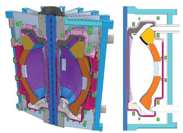
Fig. 9.4. Cross-section of the STEP spherical tokamak as shown in Ref. [59]. The left image gives a 3D cut through of the device, while the right image shows a two-dimensional slice of half the machine.
The advent of fusion start-ups during the last decade has brought renewed attention to the use of advanced fusion fuels that produce fusion with significantly reduced neutron production. The problems of radioactivity and materials damage caused by high-energy neutrons from the DT fusion reaction have led many observers to advocate for the development of so-called ‘advanced’ fusion fuels, which would create a fusion reaction with reduced neutron production, compared to DT. The two ‘advanced’ fuels generally considered most important are 1H+11B and D+3He. Reactor concepts have been proposed [63] [64] but advanced fuels do introduce new challenging problems.
H+11B → 3 4He (Q=8.7 MeV)
D+3He →4He+1H* (Q=18.3 MeV) * neutrons produced in D+D reactions
A major problem is that any other fuel would have a much lower reaction rate than DT. Because of the lower fusion reactivity, the power density in the plasma for a given plasma pressure is smaller for any other fusion fuel than for DT. Operation with advance fuels requires much higher plasma pressure in order to achieve a comparable power density implying much higher
temperature operation and increased energy confinement time or a much larger plasma volume in order to achieve the same power output. This size disadvantage may be somewhat mitigated by the reduced shielding requirement with a neutron-free fuel cycle, but the substantial fusion reactivity advantage of DT with respect to any other fusion fuel should enable the design of more compact DT fusion reactors based on any magnetic confinement concept, assuming that a sufficient Tritium Breeding Ratio (TBR) can be achieved and appropriate materials developed for a power plant.
Another point, which is often overlooked, is that the neutrons from DT fusion carry 80% of the fusion energy through the first wall to be deposited over the volume behind it, leaving at most 20% of the fusion energy to be transferred as heat through the first wall. On the other hand, a much larger fraction (approaching 100%) of the fusion energy (less any that is diverted) must be transferred as heat through the first wall or captured in some way by direct conversion of charged particles, with advanced fuels.
Advanced fuels provide an interesting opportunity for the long term, but the alternate confinement concepts with higher projected pressures which are required for plausible ‘advanced’ fuel reactor concepts are at a very early stage of development.
Different combinations of drivers, including lasers, heavy ions and Z-pinch, and targets directly coupled to the driver (direct drive) or indirectly coupled to the driver through a holhraum (indirect drive) can be envisioned as variants of the IFE approach, to develop inertial fusion energy including lasers with indirect drive targets [65], [66] as in NIF, and with direct drive targets [67]as in designs for next stage facilities such as HiPER [68]
There is an important growing effort in IFE research, with new MJ-class laser facilities, such as NIF in the USA and LMJ [24] in France, and the upgraded MJ Z-pinch ZR facility in the USA. It is also expected that globally, inertial fusion energy research will receive a major boost by the recent advances at NIF and will lead to acceleration of existing national inertial fusion energy programmes or establishment of new programmes (See section 9.3).
The projected performance of inertial fusion reactors, which are anticipated to have a large recirculating power, is very sensitive to the driver efficiency, which needs to be improved substantially from the present level for a power producing reactor. Many concepts for IFE chamber components have been advanced in design studies during the past 20 years. In general, chamber designs can be classified into three general types: dry wall, thin liquid protection and thick liquid walls. These use different schemes to ensure the survival of the first wall from the neutrons, Xrays, and target debris: gas protection for dry walls and liquid protection for the other two. In each
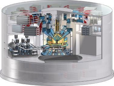
case, the requirement for survival of the first wall leads to challenging constraints on the chamber size and geometry, material choices, and maintenance of the chamber protection scheme. As an example, the LIFE power plant study [69] assumes a laser driver and indirect drive target, as illustrated in Fig. 9.5 which shows a schematic of the fusion operations building including the laser system (only the top laser beams are shown), the fusion chamber, and primary-to-intermediate heat exchangers.
Although the recent energy gain breakthrough at NIF is a major milestone on the way to inertial fusion energy production, several challenging scientific and technological open issues remain. Many of these are associated with the high repetition rate required for an IFE reactor (of the order of 1–10 Hz) including: (a) wall protection, which involves hydraulics and flow control for liquids and includes ablation damage and lifetime for solids; (b) chamber dynamics and achievable clearing rate following capsule ignition and burn; (c) cryogenic target fabrication; (d) handling, injection and tracking in the chamber environment; (e) propagation of beams to the target; (f) final-focus shielding and magnet/ optics thermal and neutron response; (g) coolant chemistry, corrosion, wetting, and tritium recovery; (h) neutron damage to solid materials; (i) safety and environmental impacts of first wall, hohlraum, and coolant choices.
Some challenges to realise fusion plants are highly concept specific, such as the development of high efficiency, high-power laser systems for IFE or developing an effective heat exhaust solution in MFE. The primary issues in contrasting the prospects of inertial and magnetic confinement reactors are the target physics and laser efficiency extrapolations required between present experience and a reactor. For magnetic fusion, the efficiency of the driver- the heating and current drive systems is less critical to projected reactor performance but can have a significant impact of the economics of a steady state tokamak or spherical tokamak.
Regardless of the core fusion system though, there are several common issues with all fusion power plant designs. This may provide opportunities for knowledge transfer and collaboration between plant designs. Table 9.2 shows a simplified list of features that distinguish ITER from the design of a succeeding fusion energy demonstration plants to explore the issues relating to a commercial fusion power plant.
Some of the overarching challenges that must be addressed in any design when stepping up from ITER include the issues of component/system reliability and the impact on plant availability, tritium breeding and extraction from the breeding blanket (to achieve tritium-self-sufficiency from day 1), tritium handling in the tritium cycle, tritium fuelling and control, nuclear shielding, remote handling and maintenance activities, and materials and their survivability in the high-energy neutron environment of DT fusion. Some further considerations on these topics are provided below.
ITER
Experimental device with physics and technologydevelopmentmissions
FutureElectricityProducingDevices
Narroweroperatingspace.
Nearer to a commercial power plant but with somedevelopmentmissions
Demonstrate adequate level of plant availability forextrapolationtoareactor.
Component reliability and plant maintenance areveryimportant.
Largenumberofdiagnostics
MultipleH&CDsystems.
No tritium breeding requirement (except small quantityinTBMs)
Conventional316stainlesssteelstructureforinvesselcomponents
Large design margins, necessitated by uncertainties, flexibility of experimental operations and lack of fully appropriate design codes.
Very modest lifetime n-fluence, low dpa and He production
Fewer diagnostics and control actuators for operation.
Optimised set of heating systems (and noninductivecurrentdriveifappropriate)
Demonstratetritiumself-sufficiency
Rely closed tritium fuel cycle tritium breeding blanket, tritium extraction, processing and recovery,tritiumstorage.
Nuclear hardened, reduced activation structural materialsforthebreedingblanket
WithITER(andother)experience,designshould havesmalleruncertainties
High n-fluence, significant in-vessel materials damage
Thermodynamicconversiontoelectricity
Cooling system optimised for minimum stresses andsizedformodestheatrejection
Experimental campaigns. Outages for maintenance and limited component replacements.
Cooling system optimised for electricity generation efficiency (e.g. higher temperature andpressure)
Maximiseavailability.Demonstrateeffectiveand efficient maintenance and component replacementtechnologies
Remote maintenance system, active handling facilities and storage, and recycling and waste management;
Demonstrate safe failure, mitigation of and recoveryfromfaultconditions
Licensingasexperimentalfacility.
Licensedasafusionpowerplant
Established codes & standards applicable to a reactor.
A recent study [70] identified the technical attribute of a fusion energy demonstration plants and their main differences with commercial fusion power plant. The examples briefly discussed here are the cost of electricity (CoE), the plant availability (see also section 9.8) and the thermodynamic conversion efficiency. The generation of electricity at an economically competitive cost is not recognised to be a necessary attribute of a fusion energy demonstration plant, at least in several programmes among the ITER participating nations. Similarly, the demonstration of availability that is comparable to contemporary industrial standards, typically 70–90% [71], is not required in a demonstration plant and given that the duty factor of existing fusion devices is less than 1%, a value of around 30% would represent a more acceptable goal, given the lack of reliability data for most components.
The same considerations would apply to demonstration of thermodynamic efficiency that is of the same order as contemporary industrial standards (typically 30–60%). It is difficult to set a specific target as there is no prior experience with a fusion device. Furthermore, the thermodynamic efficiency will be partly determined by the choice of coolant and the operating temperature of the tritium breeding blanket, which is the primary heat source of the thermodynamic cycle. Present demonstration plant designs employ water or helium cooling with an operating temperature around 500 °C. The latter is dependent upon the structural material which for present fusion demonstration plant designs is a form of martensitic steel which results in efficiencies at the lower end of the range. Supercritical carbon dioxide has been considered but would require the development of a different structural material to take advantage of the higher operational temperature.
The implications of this discussion are that there will be technical gaps between the next generation of devices that produce net electricity and economically viable power plants. In addition to closing the technology gaps, improved physics performance such as increased confinement or higher beta operation may be required to address the economic issues.
The issue of external tritium supply from non-fusion sources is recognised to be serious with major implications on fusion development pathway. In 1997, Paul Rutherford, a fusion theorist from Princeton, said when talking about the “Tritium Window for the development of DT fusion”: it is commonly believed that the timetable for D-T fusion development may be extended almost indefinitely being determined by (i) the public's recognition of the need to develop environmentally attractive long-term energy options, and (ii) the ingenuity of fusion researchers in devising superior designs for fusion reactors. This belief fails to recognise that the path to practical fusion power necessarily involves a nuclear technology testing phase, for which very substantial quantities of tritium will be required [72].
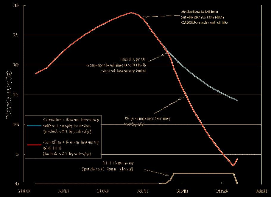
Based on the results of recent studies regarding commercially available tritium [73], [74], [75], and the forecasts of tritium production in Heavy Water Reactors (HWRs) of Canadian Deuterium Uranium (CANDU) type-reactors in countries where tritium extraction is carried out, or planned to be carried out, worst-case scenarios were identified where it would appear that there is insufficient tritium to satisfy the fusion demand after ITER (see Fig. 9.6 [76]). Tritium consumption in fusion reactors is unprecedented: a fusion reactor consumes approximately 55.8 kg of tritium per 1000 MW of fusion power per year. Tritium production rate in fission reactors is much smaller than the tritium consumption rate in fusion reactors: tritium production in light water reactors (LWRs) is limited to ∼0.5–1 kg/y whilst in CANDU type-reactors produce ∼130 g per GWe per full power-year from n-D reaction.
Ontario Power Generation group sells tritium at zero production cost at 25–30 million EUR / kg [77], [78]. The detritiation costs at the Cernavoda CANDU reactor in Romania are estimated at EUR 275 million per year (excl. capital cost) [79] i.e. tritium produced by this CANDU would cost ~158 million EUR/kg.. Future supply from CANDU depends on whether current reactors can be licensed to extend life by 20 years after refurbishment, which depends on political, national policy, and practical issues.
Furthermore, tritium generation in fission reactors requires special tritium breeding systems like Tritium Producing Burnable Absorber Rods (TPBARs) and is very expensive (∼80 –130 million USD/kg) [76]. In addition, the permeation of tritium from the rods might require special-purpose hardware for removing the rods from the core and would lead to licensing implications. Other non-fission sources, e.g. proton accelerator (APT), were proved to be uneconomical. Because of the relatively short life of tritium, which decays at a rate of ∼5.5% per year (12.32 years half-life), and the issues and limitations of tritium production in fission systems, tritium resources available now from non-fusion sources are irrelevant to evaluating availability of tritium for start-up of DEMO or other fusion devices which will be constructed 20 years from now or beyond.
Due to the limited tritium supplies available, achieving tritium self-sufficiency is an inescapable requirement for any next step nuclear fusion facility beyond ITER. This must be done with a margin sufficient to compensate radioactive decay during maintenance periods, tritium temporarily residing in materials and tritium plant, which is not available for fuelling the plasma, and for starting up new fusion plants. In addition, the site inventory will be tightly restricted by the regulator, so the amount of tritium outside the plasma at any time must be minimised and losses eliminated wherever possible.
This may have implications not only for including a breeding blanket in future DT facilities but also in restricting design and operations to reduce the tritium requirements and perhaps in constraining the tritium usage in ITER during the final operating phase.
Clearly, there is a need to better understand and monitor the future availability of tritium and understand the impact of limited resources on the timeline of future demonstrator reactors. However, there is essentially very little that the fusion community can do to exert an effect on the supply side, as tritium is a by-product of the operation of these reactors and not the primary economic incentive. Defence stockpiles of tritium are unlikely ever to be shared. The limited available tritium will also have to support both the needs of fusion start-up companies and dedicated fusion test facilities.
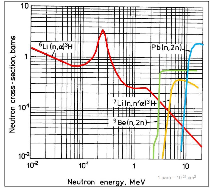
The production of tritium in a breeding blanket of a DT fusion device occur in the so-called breeder region that contains a Li-based solid or liquid material where tritium is produced through neutron capture, sustaining the following fusion reaction:
The lithium-6 reaction has a very high cross section especially in the low-energy region (see Figure 9.7). The lithium-7 reaction works with the high energy neutrons. It produces an additional n that is available for a successive reaction. Lithium-6 constitutes only 7.4% of naturally occurring lithium (the remaining 92.5 % is in the form of lithium-7). Many fusion reactor designs depend on an additional material for neutron multiplication to increase the TBR. Most blanket designs depend on either beryllium or lead as a multiplier. The latter (lead) is abundant, cheap, and geographically widespread; the former (beryllium) is not. Some blanket designs require substantial enrichment in the lithium-6 isotope due to the neutronic properties of particular blanket designs. Moreover, lithium-6 is an export-controlled commodity and worldwide production is effectively zero.
The primary problem with lithium enrichment is the lack of scalable and environmentally friendly methods for separating lithium-6 from lithium-7, which is crucial for certain advanced technologies like fusion power. Current industrial-scale enrichment relies on the COLEX (column exchange) process, which uses mercury, is expensive, environmentally damaging, and not easily scalable [80]. Work is also underway to refine the COLEX process, aiming to reduce its environmental impact and improve its efficiency and scalability. Researchers are actively exploring alternative, safer, and more efficient methods for lithium isotope separation, including those based on chemical exchange and membrane technologies. Other enrichment technologies exist, but few have been proven at benchtop scale, let alone industrial scale. Studies are investigating natural processes, like hydrothermal alteration and water-rock interactions, that can lead to lithium enrichment in certain geological formations.
Further still, breeding blanket concepts based on the use of natural lithium may avoid the aforementioned issues but potentially at a cost to the tritium breeding performance for a viable closed tritium fuel cycle. Proliferation concerns may also narrow the market for any fusion reactor that uses any level of enriched Li-6. However, identifying optimum enrichment levels that balance technical/environmental/economic feasibility with non-proliferation can facilitate public acceptance and security, which must be considered as integral to the process rather than an afterthought. These challenges should not be viewed as insurmountable, and there are opportunities for new technological approaches.
It is important to recognise that actions are needed to identify and develop effective methodologies to enrich lithium-6 to avoid a significant bottleneck or, in extremis, a resource availability with lithium-6 or supply-induced showstopper, that hinders the future rollout of commercial fusion reactors [81]
The successful commercialisation of fusion energy requires development of integrated and robust technological solutions validating all reactor systems and components in a fusion power plant environment, within regulatory and economic constraints.
As with technologies developed in other fields through an iterative sequence of activities, a guide to the maturity level of fusion design concepts is obtained using a technical readiness level (TRL) approach. The TRL scale derived from a model used by NASA [82] to assess technology development for space technology is an established metric for assessing and displaying progress in the development of technology. It assesses demonstrable technology maturity or “readiness” on a scale of 1 to 9, whereby TRL 1 is given to a technology in which only basic principles are understood with degrees of progression towards TRL 9, where full operation in the relevant environment has been demonstrated.
Assigning a TRL is a subjective exercise; it requires expert analysis and review. As it is not simply one individual component that must be developed, but the integration of several different components and systems. System Readiness Levels (SRLs) can be used to determine the maturity of combined technologies.
The design of new fusion power plants will benefit largely from the experience gained from the design, licencing, and construction of ITER, and from its crucial validation of DEMO-relevant physics and key parts of the technology basis, as shown in Fig. 9.8, increasing its TRL. Nevertheless, there are outstanding materials and engineering challenges [83], with potentially large gaps beyond ITER that need to be urgently addressed, including breeding blanket, T fuel cycle, divertor, materials, and remote maintenance. This is true for MFE and perhaps even more so for IFE.
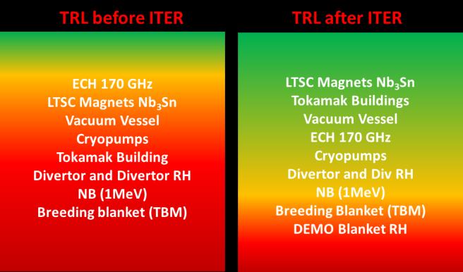
Two outstanding technological issues are the achievement of tritium self-sufficiency in the breeding blanket and of reliability and high plant duty factor for an integrated fusion reactor system. These represent potential showstoppers for fusion and are further discussed in Sect. 9.8.
The essential technology and engineering research, development, and demonstration (RD&D) areas necessary for establishing a fusion power plant are summarised below. While each area is critical, the first two are regarded as the highest priorities for DT-based fusion energy concepts.
Materials Resilient to Extreme Conditions: A major technological issue is the development of structural and other materials capable of sustained operation under cyclic stress at temperatures much higher than current LWRs, that are sufficiently resistant to radiation damage to achieve
economically relevant lifetimes of fusion reactor components. These materials need neutron activation characteristics which would enable them to qualify as low-level-waste for shallow land burial or to be recycled during decommissioning. This technology is at an early to intermediate stage of development. In particular, the shortage of material test reactors for testing material properties could hinder the development.
The EU is constructing a dedicated Deuterium-Lithium n-source facility in Granada (Spain), called the DEMO Oriented Neutron Sources (DONES), which will contribute substantially to gaining information about the degradation of material properties under neutron exposure at the high neutron fluence that EU-DEMO blankets will experience. This is mandatory in Europe for materials qualification and for the development of licensing codes. However, in these sources the irradiation volume is very small (less than 0.5 l in DONES for high-flux irradiation experiments). Therefore, it will not provide sufficient information on design reliability or effectiveness of tritium breeding and extraction. Its main role is to provide a neutron source producing high energy neutrons at sufficient intensity and irradiation volume to generate materials irradiation test data for structural design.
Tritium breeding blanket and Fuel Cycle: The breeding blanket is one of the most important and novel technical systems of any DT fusion power device (MFE or IFE) to follow ITER. Despite its criticality to the success of fusion power, the maturity of the breeding blanket is still very low with no such blanket having been built or tested to-date. There remain feasibility concerns and performance uncertainties in all currently explored concepts. The development and qualification of sound blanket concepts are, without any doubt, on the critical path for deploying fusion reactors. Given the importance of the blanket and potential associated regulatory aspects, there is an urgent need to accelerate its development and testing programme, and to ensure that adequate design data will be obtained from the operation of ITER and concurrent materials or component testing facilities, to ensure DEMO tritium self-sufficiency,
Power Exhaust: The extreme power density conditions foreseen in fusion machines during both normal operation and transient events present significant engineering challenges including for plasma-facing materials, cooling techniques and component design. This is already the case for ITER and will be even more so for DEMO-like reactors. Advancing research on suitable plasma regimes remains a key experimental accompanying programme in that respect.
Remote Handling for Maintenance: Maintenance and repair tasks must be performed remotely using advanced robotic systems. Development efforts will be needed building on the ITER experience to develop these remote handling systems for commercial fusion energy applications.
Heat Extraction: The energy generated inside the reaction chamber must be extracted efficiently and the corresponding components must have high availability, to achieve a competitive cost of electricity. This implies extracting heat at higher temperature relative to ITER operation for
improved thermodynamic efficiency. Operation at such higher temperature would require the use of advanced steels.
Advanced magnets (High Temperature Superconductor (HTS) magnets): HTS offer the promise of operating at both higher magnetic fields and higher current density coils. They also offer the potential benefit to increase the magnetic flux in the central solenoid of a long-pulse tokamak. However, quench protection of NI coils for large-scale magnets is an area in which development and qualification is still on going. The study [84], [85], [86] showed that high-field TF magnets do not necessarily lead to a reduction in machine size, as large structures are needed to withstand the forces. This is a topic of discussion within the community as can be seen in references [71] and [72]. However, even if not operated at high field but using conventional insulated coils, HTS can still offer benefits including simplifying the magnet cooling scheme thanks to the increased superconductivity temperature margin (indirect conduction cooling). This in turn can greatly simplify coil construction and minimise high-voltage risks at the terminals by decoupling the coolant and current-carrying functions of the conductor. A concern may be how well such superconductors tolerate radiation.
The integration of all the technologies needed to build a reliable device is recognised as the greatest challenge ahead. The ITER design and construction activities described in this book have, nevertheless, yielded several important lessons for those working on future steps:
1. the importance of normal and off-normal thermal transients (e.g., disruptions) for invessel component design of conventional tokamak and ST design;
2. the importance of nuclear design integration and nuclear safety and quality assurance culture during all design phases;
3. the criticality of a robust maintenance plan with clear provisions to access areas where contamination and activation could be higher than initially considered;
4. the need to address more systematically plant layout considerations, including cooling loops and auxiliary systems, and to provide adequate space to integrate all equipment, particularly in the tokamak building.
Conceptual design of commercial fusion facilities is essential for guiding fusion R&D and providing a focus for development. Conceptual design studies ensure that all physics and technology aspects are integrated within constraints imposed by physics, materials, and technologies to produce a system that is technologically feasible and economically and environmentally attractive. Through investigation of the interactions among physics and technology constraints, optimum goals are set and high-leverage areas identified which in turn guide even the current R&D effort.
The efforts and development times for the introduction of new materials, technologies, or manufacturing processes are often underestimated. For instance, developing and qualifying new
and stronger structural materials for ITER magnets has been a long and arduous road. Large reactor-scale magnets need large quantities of such steels [87], and novel steels (often with unusual constituents such as Nb or Mn) come with novel forging and welding problems to which industrial suppliers are unable to offer solutions.
Multiple high-strength steel developments for ITER, launched in the 1990s, were all discarded by 2010, with one exception (used in the inner leg of the ITER TF coil cases) and, even here, the original targets had to be much relaxed. An example of the problems that can occur with novel (and not fully investigated) steels is discussed elsewhere [88]. Another notable example was the development of a nickel-based super-alloy, called Incoloy as a jacket material for Nb₃Sn. Although thermal and mechanical characteristics of Incoloy were deemed promising, it was found to be highly sensitive to oxygen embrittlement [89]. Therefore, although Incoloy was used successfully in the ITER model coils, the risk of catastrophic failure in operation arising from the problems of oxygen control in large-scale industrial production were unacceptable. As a result, Incoloy was finally eliminated as an option from the magnet design in 2003. In addition to materials development time, there is a significant lead time for the development of manufacturing processes and tooling.
Another example is the potential application of vanadium-alloys that was considered for the first wall of ITER in 1993. The main reason for this preference was that vanadium alloys can accommodate higher heat loads than austenitic and martensitic steels. Other favourable properties included neutronic properties (low nuclear heating rates, low impact on tritium breeding performance and low helium generation rates), intrinsically low activation, excellent tensile and creep properties up to high temperatures, and high strength-to-density ratio.
Not all these properties were necessarily relevant for ITER, but they could have been important for longer term application in DEMO reactors and beyond. A serious attempt was made to understand the benefits and the risks and to estimate a minimum time and cost necessary to execute all the R&D activities to get a well-qualified alloy. It was concluded that about 30 years would have been needed to carry out the qualification, involving irradiation in material test reactors which are becoming scarcer. The total estimated cost was of the order of 400 million EUR in today’s currency. For comparison, the development time for fission reactor materials exceeded 30 years in all cases.
There are multiple strong shortcomings of vanadium alloys, including the high reactivity with nonmetallic elements, such as O, N, C and H (which can lead to embrittlement during the welding and prolonged operation at elevated temperatures) [90], [91], [92], very high H solubility which could negatively affect fusion plant tritium inventory and embrittlement due to neutron irradiation at low-to-medium temperatures.
The two most critical areas, however, appeared to stand out in imposing constraints on operation of vanadium alloy structures in ITER: low temperature radiation embrittlement and high hydrogen
isotope solubility. At temperatures in the range 200–400 0C, which was of relevance for the ITER design concept, radiation hardening severely limited ductility and induced low fracture toughness of vanadium alloys, even at low dpa levels (<0.5 dpa) [93], [94], [95]. Without precautions such as hydrogen permeation barriers, the atomic hydrogen/tritium concentration in a vanadium alloy first wall at temperatures below 300 °C would exceed 1%, which is an order of magnitude more than could be tolerated from the point of view of mechanical properties. To mitigate these effects, coatings to form tritium permeation barriers would be required. The only alternative would be to be to operate the machine with liquid lithium in contact with the vanadium alloy structure, which would ensure a sufficiently low hydrogen concentration.
However, in this case, because of the electrical properties of liquid metal, such as lithium, all the pipes would need to be coated with electrical insulators to minimise electromagnetic forces which would otherwise lead to unacceptably large pressure drops. Due to the then-anticipated tight development schedule of ITER and the associated need to realise and license its engineering design within a relatively short term, austenitic stainless steel was finally adopted because there was no other structural material with a comparably wide database that would be compatible with water coolant, and for which the limitations were well characterised and acceptable. For instance, it was well established then that swelling would start being a problem only when the fluence had reached values of ~10 dpa, exceeding the ITER design requirements.
Solution annealed 316L offered also enough ductility in terms of total elongation to withstand any plastic deformation in case of a mechanical overload. There was a general consensus among the ITER participants at the time not to base the reference design on the questionable success of R&D on key issues of new concepts. To the knowledge of the authors only limited R&D has been carried out on vanadium-alloy for fusion applications since ~2007. In view of the short deployment times advocated by some of the proponents of new advanced reactor concepts, the long times to develop and qualify new materials, including vanadium, should be considered.
9.8.1 Performance and Lifetime Issues of Structural Materials for InVessel Components
The performance and lifetime of structural and PFC materials for in-vessel components is among the foremost considerations for the successful development and deployment of future fusion reactor systems. The very demanding operational requirements (e.g., elevated operating temperature, possible cyclic operation with long hold time, prolonged periods of operation, steep temperature and stress gradients, multi-axial loading, high neutron irradiation damage and very high production rates of helium and hydrogen as well as corrosion/erosion) that the structural materials will experience in a DEMO and future fusion power plants are beyond today’s
experience (including ITER and fission reactors). The challenge is both to improve material properties towards increased radiation resistance as well as to predict failure mechanisms and lifetime under service conditions.
There is a history of more than two decades of R&D on structural materials for in-vessel components, conducted in the US, Japan and the EU, and nowadays in China and India as well. Based on the service and environmental conditions, the R&D for blanket structural materials focuses on martensitic-ferritic steels with main alloying elements Cr (8–10%) and W (1–2%).
Dependent on the application conditions, e.g., on the coolant, the cooling temperature, the operational mode (“short” cycles or quasi steady state conditions), the material needs to be optimised in its composition as well as its thermal or thermo-mechanical treatment. For the component with the highest heat flux, the divertor, there is no unique approach. For water-cooled design options, as for example in ITER, copper alloys (Cu-Cr-Zr) are the most suitable candidate materials, which have been well developed and characterised.
One of the most recent assessments of the state of development of neutron-resistant structural, high-heat flux and plasma-facing materials suitable for use in a fusion reactor can be found elsewhere [96], [97]. In addition to conventional R&D issues, predictions of degradation of mechanical properties and lifetime are a fusion-specific challenge. Irradiation campaigns are widely performed in fission material test reactors; however, they might not result in conservative data for fusion engineering. Due to the fast 14 MeV neutrons, the production rate of helium (or hydrogen) under a plasma fusion irradiation spectrum is order(s) of magnitude higher than under fission conditions, e.g. the production of He in steels is 40 times higher. There is some evidence though, that the additional effect of He on the swelling and embrittlement of martensitic steels is limited below about 30 or 40 dpa.
Several neutron sources are already available (e.g. materials test reactors), which can provide the required neutron flux. However, their energy characteristics are very different from those of a fusion reactor. Consequently, they can be of interest to study material irradiation effects, but they are not useful for the qualification of the materials in a fusion reactor. For example, neutrons produced in fission reactors have a lower energy (typically up to 1–2 MeV) and the number of transmutation reactions will therefore be much smaller than in the case of neutrons produced in a fusion-like environment with its 14 MeV neutrons. Conversely, the energy spectra of the neutrons produced in spallation sources have a very high-energy tail and, consequently, the number and type of transmutation reactions are much higher than in the case of a fusion-like environment [98]
In recent decades, a variety of concepts have been proposed for building a neutron facility for materials qualification. Most of them are based on the production of neutrons by the interaction between energetic light ions (usually D) and a light target (like Li, C or Be). In the latter case, the neutron spectra produced are not exactly the same as those in a fusion reactor, but the predicted effects in the materials have been assessed to be similar. As mentioned in Section 9.8.3, this is the
approach used by the DEMO Oriented Neutron Source (DONES). The principle is based on Li (d,xn) nuclear reactions taking place in a liquid Li target when bombarded by a deuteron beam.
The DONES Facility will produce a 125 mA deuteron beam, accelerated up to 40 MeV (5 MW beam power) and shaped to have a footprint in the range from 100 mm x 50 mm to 200 mm x 50 mm, providing an irradiation volume of up to 0.5 l that can house around 1000 small specimens irradiated to a high dose rate (over 10 dpa/ fpy). The beam will impinge on a 25 mm thick liquid lithium target intersecting the beam with a transverse velocity of about 15ms-1. The Li (d,xn) stripping reactions will generate a large number of neutrons (up to 5×10¹⁸ n/m2s) that will interact with the material samples located immediately behind the lithium target, in the Test Modules [99]
An interesting alternative approach to producing neutrons on a larger volume is represented by the so-called plasma-based 14 MeV volumetric neutron sources (VNS) in which a plasma device with small energy gain (Q<1), but with external heating and an external supply of D and T is used to produce 14 MeV neutrons. Examples are: 1) the Gas Dynamic Trap (GTD) [100] based on a special magnetic mirror system for plasma confinement; and 2) other closed magnetic field configurations, like the so-called Two Energy-Component Tokamak Reactor [101], [102], [103] Energy ‘break-even’ in any beam-heated reactor was recognised to be attainable with far less stringent plasma performance than in other fusion reactor schemes aimed at energy production. For this application, the most important system parameter is fusion power density (that is, neutron production rate) rather than power multiplication.
Conversely, to increase the energy gain (Q) significantly beyond the break-even level requires considerably better plasma confinement and somewhat higher plasma temperature, and thus considerable improvements in plasma confinement, plasma purity, power exhaust and plasma stability. VNS concepts are all based on a beam-to-target fusion approach where a near Maxwellian background plasma is sustained against energy and particle losses by neutral beam injection, and fusion reactions principally occur between the fast and target ions as the beam thermalises via Coulomb collisions.
These VNS concepts [104] are currently under investigation in Europe [105] to reduce DEMO technological risk by testing and qualifying necessary breeding blanket and other system technologies, confirming the reliability of nuclear components as well as materials necessary for DEMO prior to its construction. These low-Q driven concepts differ from recent proposals of fusion devices made for component testing utilising small aspect ratio tokamak plasma configurations with a less extensive plasma database (see for example [106], [107], [108]). These rely on the successful execution of a physics mission prior to the nuclear mission in the same VNStype device.
A VNS is complementary both to ITER, which is focused on burning plasma physics, and DONES, which is focused on large dpa in small material samples in small high flux testing volume (<1 l of
volume). However, the use of D-Li source, like DONES in properly instrumented and sufficiently large medium flux testing volumes could be useful in providing basic data, screening of blanket concepts, and establishing the infeasibility of some blanket concepts but cannot replace more representative, complex and extensive tests in a fully representative fusion environment which is needed to establish the engineering feasibility (e.g., performance and reliability) of blanket components. None of the critical issues can be fully resolved by testing in non-fusion facilities alone. Non-neutron test stands, fission reactors, and accelerator-based neutron sources (including the D-Li source) are unable to simulate the multiple effects of the fusion environment, and they cannot provide adequate space to test articles with relevant material combinations configurations, and dimensions.
Achieving tritium self-sustainment in the breeding blanket will require a form of breeder which must produce an acceptable ratio of tritium to fusion neutrons to allow for a closed fuel cycle, with surplus to start up subsequent power plants. The design of the breeder and associated tritium plant must be maintainable and must be demonstrably safe with regards to the release of tritium into the environment. However, despite the large amount of R&D in this area in most of the ITER Members, no fusion blanket has ever been built or tested. Hence, its crucial integrated functions and reliability in DEMO and future power plants are by no means assured. In addition, ITER presents a first and unique opportunity to test the response of representative component mock-ups, specifically called Test Blanket Modules (TBMs) at relevant operating conditions, in an actual fusion environment, albeit at very low neutron fluences and employing different breeding concepts.
A summary of the critical R&D issues to be resolved for the breeding blanket are described elsewhere [109], [105] together with the testing needs for its development and qualification. It is rather striking to recognise certain analogies between the design of the first wall/breeding blanket system in fusion and fuel assembly in fission reactors [110]. Albeit with different lifelimiting phenomena, they both experience very high surface and bulk heat fluxes and are subject to large neutron damage. Performance and reliability are the main design drivers for the breeding blanket. Due to its function in tritium and power generation, it is generally recognised as impacting the safety functions of tritium control, heat removal, and confinement of radioactive material.
Accordingly, the production of tritium in the breeding blanket is generally considered an important safety activity that may require demonstration and qualification before licensing a future fusion reactor depending on the regulatory requirements. One of the main knowledge gaps is the identification of failure modes and quantification of failure rates. Prior studies [111] have shown that the availability of the blanket system must be higher than 88% to meet a DEMO target availability goal of 50%. Since the time to replace blankets is long, the Mean-Time-Between Failures must be long enough to achieve a high availability target goal. Knowledge of failure modes
and rates is necessary for the breeding blanket because of their critical impact on plant availability and safety.
There is virtually no data on breeding blanket failure modes and rates under fusion reaction conditions (i.e. under energetic neutron and gamma irradiation, high-temperature gradients, subjected to high magnetic forces, under vacuum, etc.). Prudent selection of feasible and attractive designs is extremely difficult without such data. Possible failure modes are discussed elsewhere [105].
A credible risk mitigation plan should consider the following factors:
a) limitations on the external T supply to provide the large T startup inventory required for any major fusion facility
b) technology and physics uncertainties in achieving tritium self-sufficiency
c) Reliability/Availability/Maintainability/Inspectability (RAMI)
d) complex and new multiple/synergistic effects and interactions phenomena (which cannot be synthesised from “separate effects” experiments or modelling)
e) nuclear heating in a large volume with steep gradients.
Issues (b), (c), (d), and (e) should be adequately addressed only in the fusion nuclear environment of a DT plasma-based facility. Issues (a) and (b) mandate that the DT plasma-based facility must produce modest fusion power (< 50 MW) to minimise tritium consumption and depend on externally available tritium supplies. A higher power would curtail the operation of the facility without the ability to breed sufficient tritium during its operation. Issue (c) requires a very aggressive RAMI programme.
As mentioned in Section 9.9.1, Europe is exploring the technical feasibility of a plasma-based 14 MeV VNS. This would be a compact, driven device with reactor-relevant neutron wall load and fluence to test, develop and qualify fusion nuclear technology components (like the breeding blanket) required for operating a DEMO reactor aiming at electricity production. The design and construction would proceed in parallel to ITER and would provide complementary information for the finalisation of the DEMO design. Proposals of building dedicated testing facilities are made in fission to accelerate the deployment of reliable Commercial Advanced Nuclear Energy Technologies [112]
A fusion power plant contains many complex interdependent subsystems. The ultimate ability to deliver power reliably to the network therefore depends on careful subsystem design. Even if the fusion power source operates in steady state, there will be scheduled outage times when, for instance, blanket, first wall or divertor components need to be replaced. With sufficient materials development, this should be able to be kept to intervals spaced years apart, allowing such replacements to be scheduled for convenient times of lower consumer power demand, or when other plants are available.
The complexity of fusion plants is sometimes invoked as a reason they will never work. Nevertheless, we know from other complex systems that each development step leads to increased reliability. The problem for fusion is that, because the steps from basic experiment to commercial design are few, it will be important to demonstrate continued improvement in plant availability or duty factor to provide confidence in developing subsequent steps. Modelling interdependent complex systems quickly runs up against the uncertainty of the data to be used for the mean time between failures of individual components, as well as the mean time it takes to repair. Inevitably, this data spread will show that there are circumstances under which a plant will have insufficient availability.
The design needs to incorporate a) sufficient redundancy, b) ease and rapidity of maintenance and repair, and c) anticipation of failure and contingency planning to achieve the availability targets. Inevitably, however, if a key reactor component fails, power production will cease, and so every possible failure has to be considered in the design, not only to try to avoid it or to guide the ramifications onto a quick-recovery path, but to ensure if it does occur there is a safe and minimum-damage outcome, and that a rapid recovery sequence can be implemented.
For fission reactors, a probabilistic approach is taken to event analysis. This relies on event and fault tree analyses which are only at the development stage for fusion devices. For fusion devices, reliability, availability, maintainability and inspectability (RAMI) studies have been made for some sub-systems, allowing a probabilistic analysis of their reliability to be calculated. An alternative is a top-down approach [113], which divides the plant desired reliability hierarchically into the reliability per subsystem, per component, and per failure mode. Such an arrangement can then be analysed probabilistically, and the design adjusted to meet the failure mode reliability required to have a high probability of the overall plant meeting its reliability objective.
Existing experiments largely do not use DT, so do not encounter the full consequences of failures, or the delays in restarting that may be caused. Operating the Tokamak Fusion Test Reactor (TFTR) in the US and JET in Europe brought some important, but limited experience with this. It affected outage planning and how to respond to failures around the machine. The constraints of real-world
licensing on restarting operation are also only just becoming apparent. ITER will provide valuable information on RAMI in fusion systems.
Critical to the performance of a fusion plant will be the proportionate amount of time spent producing energy, known as the availability of the plant. For current energy power plants, this number is typically in the range of 80–90%. As it is described below this number is determined by the failure rates of individual components and the time to replace them, but also by unplanned stoppages of the plant core, and the time required to bring the system back online as well as planned outages. For a fusion reactor, unplanned stoppages may include off-normal events in the core fusion system which require shutdown and restart, but the reliability of the entire plant must be considered (though component failure in the fusion core remains a key risk).
The availability allocation among components of a fusion reactor system to achieve a target availability has been performed for reactor designs like INTOR [114], STARFIRE [115], and Next European Torus [116]. These studies have shown that to meet overall availability goals of about 60% a blanket system availability of more than 90% is required. These values are estimated based largely on expert opinion and the data obtained from the experience of non-fusion technology.
Failures and reliability are among the most serious concerns in the engineering development of a component. This will be even more so for fusion power plants which have more additional auxiliary systems (such as cryogenic system, vacuum system, high-voltage power supply, and tritium and fuel cycle system) than the existing nuclear fission plants. Reliability and availability analyses reveal critical concerns that need to be addressed in fusion power development including: the mean time to recover from a failure is relatively long, the surface area of the first wall is relatively large, and the vacuum environment will not tolerate operation with leaks from blanket modules.
All these factors require that the failure rate be very low, or alternately, that the mean time between failures (MBTF) be very long. Therefore, reliability growth and demonstration testing are extremely important for blanket development, and a serious reliability/availability analysis must be an integral part of the design process. As presently envisaged, ITER will provide valuable data on plant availability but was not designed to the requirements for a DEMO mainly because of the low duty cycle, low fluence, short continuous operating time, and small number of blanket testing ports. Non-fusion facility tests cannot replace the need for a comprehensive testing programme in fusion facilities.
This is motivating the consideration of another route to develop, test and qualify critical blanket technologies like the breeding blanket as described in Section 9.9.2. In parallel, there is the urgent need to establish a reliability growth programme in fusion, to ensure the development of reliable components. Reliability analysis and statistical methods have been used with great success to determine reliability testing requirements in aerospace, defence, and other industries [117],
[118]. The study [104] derives quantitative guidelines for testing requirements, including fluence, by applying available reliability analysis methods to the fusion blanket reliability testing problem.
To analyse the impact on the Cost of Electricity (CoE) arising from these considerations, the CoE can be estimated [119], [120], [121] as follows:
where the lifetime cost includes elements for the total construction, operation (including staffing costs) and maintenance, interest on loans, replacement items, deuterium and tritium, and decommissioning costs, A is the plant availability and Pe the net electrical output.
A study [122] conducted in the past showed that for a 10th of a kind 1GWe power plant, the CoE is dominated by capital costs. As most of the lifetime cost elements are minimised by small size and simplicity, for MFE this has resulted in a trend to try to reduce the physical size of the device and increase the physics performance.
However, the plant availability and the net electrical output also play an important role in CoE. Other engineering and physics factors would of course come into play when designing the reactor (such as limits on the divertor and first wall heat transfer, plasma confinement requirements, and minimal shielding requirements) but it is important to consider the whole picture including CoE when designing and sizing a fusion power reactor.
No economic studies of demonstration plants exist, but it is likely that the contributions of the core and operations to the cost will be proportionately larger given their FOAK nature while the capital and decommissioning costs will be similar. A parametric study of the operational performance factors contributing to the cost of electricity [123] showed that plant availability was the major single contributor in the operational contribution as shown in the parametric equation for the operation and maintenance (OM) costs:
where A is availability, η is the thermodynamic efficiency and Pe is the net electrical output. From a practical point of view, availability is the ratio of operating time to the sum of operating time and downtime during experimental campaigns, and A is defined as
where the sum is over all relevant systems. Generally, an availability of 30% is considered adequate for a demonstration plant and subsequent studies have shown that even this value is challenging.
While availability is largely determined by the remote maintenance scheme, the mean time between failures is determined by the reliability of any given subsystem or component and is thus directly related to the design, manufacture and materials choice. Thus, it is essential that key drivers of a demonstration plant are design for maintenance, maintainability that translate primarily in accessible to remote handling in terms of lifting points, fixings, mass, centre of gravity; design for manufacture by using qualified materials with a readily available supply chain, feasibility of manufacture using existing methods, finished product accessible to inspection; and well defined and feasible testing requirements and qualification programmes. Of course, the impact of these on capital costs will have to be considered.
Validating and qualifying essential fusion core component, like the breeding blanket, would benefit from VNS facilities which are yet to be developed (see Sects. 9.8.2 and 9.8.3). Results from these facilities would increase the availability of DEMO or pilot plants, and give greater confidence in achieving a higher value of TBR, which would minimise the need for external tritium resources. The alternative is to have the testing and development be part of the programme on DEMO or the pilot plant. There is also a need for other test facilities to resolve outstanding issues associated with the breeding blanket, fusion fuel cycle, materials and power exhaust.
The public programme in support of the fusion startups would continue to conduct fundamental scientific and technical research to improve the concept and address technology issues with test facilities, addressing near-term issues while having a longer timeline perspective. Even in the mature nuclear fission industry public programmes support the industry with both a near-term and long-term focus.
The safety for operators, the environment and the public of future power plants is a prerequisite for the successful deployment of fusion energy. The safety approach for fusion energy systems needs to be consistent with the IAEA’s Fundamental Safety Principles (SF-1) [124] which apply to all circumstances that give rise to radiation risks, including uses in the medical field, power generation, or industry applications. The fundamental objective is to protect people and the environment from harmful effects of ionising radiation. Some of the hazards are design or technology and material interaction dependent (e.g., lithium and water) and need to be considered to reduce hazards and minimise radioactive waste, where feasible.
9.9.1
Fusion plants substantially differ from existing fission power stations and existing regulatory frameworks may not be appropriate for fusion (though ITER operates under an existing nuclear regulatory framework). Except for concepts relying on advanced fuels, tritium will be a key
consideration for any future regulatory framework for fusion, and will necessarily include safety, licensing, and operational guidelines. Future fusion reactors, like ITER, will contain the following radioactive materials: tritium, neutron-activated elements in structural and plasma-facing components, and neutron-activated elements in cooling systems from the coolant and piping corrosion (activated corrosion products (ACPs)).
Significant amounts of tritium need to be transported from tritium production sites, mainly the CANDU type reactor sites to the tritium plant building of ITER [125] and in the future, to fusion reactors to provide the required amount of tritium for reactor startup, discussed above. Tritium will be present in process piping and tanks as HT or DT gas, in coolant piping as HTO, inside the plasma as an ion, in the plasma facing components, or in dust. The tritium inventory in the fuel processing and cooling systems is segregated so that the entire inventory cannot be mobilised by a single accident. Some of the activated elements in plasma facing components, however, could be mobilised as dust particles under accident conditions. The quantity of activated tokamak dust for ITER and next-step machine is still very uncertain.
The quantity of activated materials inside the coolant piping is of the same order of magnitude as that in the cooling system of fission reactor plants (of the order of 10 kg total, of which less than 10% would be in solution and the rest deposited on the interior of the cooling system surfaces). The total activity for a stainless-steel blanket and cooling system is of the order of a few curies (mostly Manganese-56). Consequently, the primary radiation hazard from a future fusion reactor, arises from its tritium fuel. This constitutes the environmental source term for a postulated worstcase (unmitigated) accident in a fusion reactor. Some fusion concepts may have lower tritium inventory requirements, which would be advantageous.
There is a need to develop a risk-based regulatory approach that is proportionate, and which aligns with the unique profile of fusion as a novel technology- and is not based on fission. This would ensure that regulation is robust (rigorous and safe) but does not stifle technological progress.
In 2022, the UK Government published a Green Paper [126] confirming that fusion will be regulated under a different framework than fission. With this different policy approach and the Government’s proposal that fission regulation should not apply to fusion energy facilities, a fusion specific National Policy Statement (NPS) was identified as essential to provide clarity to developers. In the US, in 2023, the Nuclear Regulatory Commission (NRC) announced that fusion energy would be regulated in the United States under the same regulatory regime as particle accelerators [127]
Such an approach, listed in the United States under the byproduct materials regulatory regime (10 CFR Part 30), would separate the regulatory oversight of fusion from the utilisation facilities regime (10 CFR Parts 50 & 52) that regulate nuclear fission energy.
At this point, there are many different approaches to developing an electricity producing fusion facility. Safety assessments will address the unique safety and environmental issue of each approach. Some approaches due to the potential risks, may require different regulatory frameworks than those being pursued in the UK and US. As noted above, this is likely to be the case for fusion-fission hybrids but may also occur for designs with much larger tritium inventories or have other major radiological hazards. This may motivate the development of a fusion specific regulatory framework as opposed to modifying existing frameworks. Ensuring safe operation is of utmost importance, and designs must pass rigorous safety assessments before being granted regulatory approval. Maintaining transparency with the public is also critical, as regulatory frameworks must balance public concerns with scientific evidence to ensure public confidence in fusion technology.
Member States are currently evaluating means to regulate fusion energy systems commensurate with their risks. This approach is reflective of the IAEA’s graded approach to regulations [128] Requirements and guidance already exist or are being developed in Member States for fusion energy systems and safe management of radioactive waste, consistent with national frameworks and the associated hazards. These requirements and guidance address both safety and security.
The IAEA can support regulatory bodies in developing safety requirements for fusion energy, as has been done for other regulatory regimes. Cooperation among regulators is advantageous. Common approaches and consistent decision-making across Member States, where feasible, will streamline the application process, as designers will have less need to revise their applications, technical solutions and justifications across jurisdictions. Common terms and common positions on technical matters can aid all regulators, even if different regulatory approaches are applied.
Regardless of the core system, several regulatory considerations will likely apply to any DT fusionbased power plant. A prime regulatory concern will be impact to the local environment. Careful plant design and controlled handling of tritium will be important to minimise impact on the local environment in worst-case scenarios. The design of the tritium cycle will also determine the total inventory of tritium within the plant, which will have implications for licensing, so inventory minimisation is a major design driver. While the fusion reaction products are not active, the presence of high-energy neutrons will cause transmutation in materials of the machine, and the presence of tritium will lead to residual tritium embedded in machine components.
Accurate prediction of waste and design of waste recycling, detritiation, waste management and decommissioning strategies will likely be regulatory requirements for the licencing of fusion plants. A panel of European experts was convened in 2023 to formulate a set of recommendations for the safety and licensing framework governing fusion power plants. The panel assessed insights
from existing fusion facilities, International Atomic Energy Agency and European Commission reports on fusion power plant safety, and ongoing initiatives by the UK government, US NRC mentioned above and the Canadian Nuclear Safety Commission. Additionally, ITER’s licensing process was reviewed, as the most recent licencing exercise. Twelve recommendations were presented on regulations, international databases, codes and standards, safety demonstration rules, and regulatory approaches [129]
The analysis brought to light certain commonalities between fusion and fission technologies in terms of fundamental safety objectives, potentially paving the way for alignment in specific aspects of the regulatory framework. However, it also unveiled notable distinctions, particularly regarding the inherently lower hazard potential associated with fusion power plants. The challenge is to develop an approach that remains proportionate to the safety challenges inherent to each technology, based on the physical principles underpinning fusion and fission reactors, along with their respective technologies. Recognising these differences is of paramount importance for the future development of regulatory frameworks. Additionally, the process will be expedited if standardisation of approaches towards elements such as radioactive waste classification and design codes together with a consensus on the regulatory framework basis can be achieved through bodies such as the IAEA.
Establishing regulatory frameworks ultimately depends on a nation's legal framework. Therefore, the realisation of a binding universal fusion power plant regulatory framework appears unattainable. However, much like the prevailing regulations governing nuclear power plants today, there is an opportunity to foster harmonised approaches to the minimum level of fusion power plant regulation. These approaches aim to provide consistent minimum levels of protection across jurisdictions.
Regulatory bodies would be key actors and stakeholders in the establishment of a fusion industry. They will need to build their own skills and competencies as the technology develops, including through collaboration with industry and research institutes. Collaboration across national regulatory bodies is also important to ensure sharing of knowledge across jurisdictions, support the establishment of newer regulators as well as to accelerate regulatory harmonisation. All of those are key to the development of an international market of critical size.
International organisations such as the IAEA can help facilitate bilateral and multilateral discussions among Member States developing similar regulatory frameworks. Coordination within the IAEA for consistency and coherence of effort will support all Member States in advancing their fusion regulatory structures. A decision on whether IAEA should develop safety requirements for fusion may not be warranted until fusion energy systems have matured and there is a better understanding of the associated hazards.
In the ITER design, numerous existing codes & standards, such as ISO, ASME, IEEE and ASTM, have been applied to demonstrate the design robustness, quality and safety. The codes and standards
applications have also helped the licensing process. Similarly to the fission plant design and any other industrial products, proper codes and standards which can be directly applicable for fusion reactors shall be defined and/or developed if needed in a coordinated manner among Member States.
Aspects of the underlying science in IFE are closely coupled to that of nuclear weapons. The proliferation risks associated with some aspects of IFE R&D are in the acquisition and dissemination of scientific data that would facilitate designing nuclear warheads [130]. The sensitive information is tightly controlled and subject to export control restrictions.
Magnetic confinement is not completely immune from the proliferation issue. The Russian Federation continues to pursue, with its refurbished T-15 MD experiment, the concept of using the tokamak in combination with a natural or depleted uranium, thorium, or radioactive waste blanket, in a "fusion-fission hybrid". In principle [131], [132], [133] such a device could have a better ability to breed tritium from lithium using uranium as a multiplier rather than the more conventional beryllium or lead multiplier. Natural lithium is 92% Li, which requires neutrons more energetic than 2.5 MeV to produce tritium and an additional neutron.
Unfortunately, fission (for instance) of U produces neutrons with average energy of 2 MeV, which can only react with the 8% Li in the blanket to produce tritium. Making a success of the hybrid, therefore, depends strongly on the ability to manage the overall neutron economy, along with the enrichment of lithium in the blanket, and the control of the relative amounts of uranium, thorium or plutonium isotopes in the blanket. Although it is, in principle, possible to work with natural fissionable or fissile materials to make the energy balance work, it is likely that reprocessing of these materials would be required, raising the risk of diverting materials for use in nuclear weapons. The regulatory framework for a fusion-fission hybrid, including the applicability safeguard controls is expected to be different from the controls for a pure fusion power plant.
It is important to emphasise that despite the distinctions above, fusion energy systems are intended to be used for peaceful purposes. Regulatory oversight will assure that fusion energy systems’ risks of non-proliferation are demonstrated to be acceptably low. The IAEA’s international safeguards have not been applied to existing fusion devices. Depending on the designs developed in the future, particularly if designs were to use nuclear sensitive materials (or special nuclear materials) or are designed to produce nuclear sensitive materials, existing international safeguards agreements may apply. Some Member State regulatory frameworks include additional non-proliferation controls typically under their export control regulations for relevant materials, such as tritium, and certain dual-use technologies and software and analysis codes that can be used for both civilian and military applications. Designers should be mindful of these provisions.
The improved understanding of the physics of fusion plasmas and the advent of new technologies such as for example high temperature superconducting (HTS) magnets for tokamaks, and low-cost plasma drivers and lasers, have stimulated the emergence of many entrepreneur-led and privately funded enterprises, referred to as fusion start-ups, all of which are aiming to develop fusion on a fast timescale. Most of them are all pursuing alternative designs concepts (either non-tokamak configurations or alternative fuels).
In contrast to public fusion programmes, private fusion start-ups are backed by investors who naturally want to see rapid development towards a commercial product as well as a return on investment. Private sector start-ups have a higher acceptance of risk, and by rapidly learning and adapting from failures, fusion start-ups expect to make significant progress measured in the order of years rather than decades. The approach of the start-ups, as in the public programmes 70 years ago albeit with the technology then available, is on building, testing and learning iteratively on rapid cycles, which it is argued could facilitate accelerated development towards an explicit commercial goal even at the extent to accept failures.
This approach has been used successfully in the space exploration sector, for example, by SpaceX [134]. However, there are reasons to believe that this might be harder to apply to fusion. In contrast to fabricating and launching advanced rockets and spacecraft, where substantial prototypes already have launched successfully, future fusion reactor concepts entail large uncertainties and unprecedented extrapolation in physics and nuclear technology moving towards reactor concepts. Many of the physics and technology features require substantial development and testing in an adequate fusion environment.
The development of new concepts and technologies requires a thorough examination of system integration aspects to ensure that the integrated view of the plant is maintained from the very beginning and all factors affected by the numerous design choices to be made are identified, evaluated, and properly weighed. Implementation of this approach provides an opportunity for overall design convergence, reduction of integration risk and minimisation of lifecycle costs at an early stage of the design. The development of an integrated design is done in parallel with the research and development of the fusion concept and underlying technologies.
Another important consideration that must be accounted for is that high tech development cycle for the introduction of new materials, nuclear technologies, or manufacturing processes is often underestimated. The examples given in Sect. 9.8.3 and others described in Chapter 4 point to a development cycle of the order of 20–30 years. This may result in incorporating new materials with improved performance in subsequent versions of the concept just as the airplane evolved from the biplane to modern jets. Programmes and companies that aim to build first-of-a-kind fusion reactors need also to consider the costs and time of building up the relevant supply chain.
Lessons learned from comparable projects have highlighted the importance of involving industry during the early phases of the design development – especially for complex nuclear infrastructures. For instance, Advanced Fission Systems, like Gen IV and SMR programmes have leveraged impressive support and engaged with industry as a partner from the outset. Work conducted to date in the conceptual design activities for DEMO in Europe [3] have highlighted a number of areas where harnessing of industry competencies can have significant impact during the conceptual phases in areas such as; (i) support in establishing systems and project management processes to deliver the project; (ii) translation of experience in obtaining construction and operational licenses for nuclear infrastructures, as well as pre-qualification of components and systems; (iii) identification of the applicable codes & standards applicable for the fusion reactors; (iv) assessments of design and technology maturity and prospects for licensing; (v) experience in industrial plant design and integration; (vi) development of concepts for major components and systems that incorporate manufacturability considerations; and (vii) cost assessments.
The successful transfer of fusion technologies from research and early development to commercial applications will be critical to the establishment of a thriving fusion industry. Traditionally in Europe, large-scale national and international projects have served as de facto "anchor tenancies" (a long-term commitment by a government to provide a stable revenue base and reduce financial risk for private companies), contributing significantly to maintaining the supply chain and human resources. To further develop the fusion industry, the public sector should continue to play an active role in sustaining the supply chain through its public programmes, including establishing new commercially relevant research facilities, to ensure a seamless transfer of knowledge and expertise accumulated in public programmes to industry under adequate arrangements (e.g., licensing). Establishing clear regulatory and IP frameworks are critical enablers.
One challenge to the transfer of technology from public-funded research and development is the lack of investment in technologies that are not fully mature for demonstration. Identifying opportunities for public-private consortia could bridge supply chain ecosystems to fusion energy developers bringing both public funding and private capital to build technology development platforms with shared risk.
The realisation of large fusion infrastructures like ITER or NIF has clearly identified all the challenges arising from the realisation of FOAK components/systems. Lessons learned from ITER’s experience in hardware contracting, fabrication, and delivery can inform future fusion projects and the fusion supply chain of some common challenges and their possible solutions. Experience in each stage of ITER component development has yielded improved understanding of best practices and risks in moving from design to final delivery.
Lessons learned include evaluating manufacturability early in component design, selecting contracting strategies which enable contract success, identifying suppliers and supporting supplier development for fusion components, prototyping to reduce risk and ensure overall delivery success, leveraging public and private experts and facilities which enable component completion and acceptance, and performing qualification and testing of components for fusion environments.
Planning, designing, constructing, commissioning and operating new fusion energy systems will require a robust supply chain spanning many domains, some of them very fusion specific but many of them common to other industries. Potential actors of the fusion supply chain include fusion technology vendors, key material providers and component manufacturers, plant engineering companies, general construction companies, equipment suppliers and service providers (specialists as well as non-specialists). Such an extensive supply chain is likely to be international. The building of the workforce as well as the development of its competencies and know-hows (e.g. the development of manufacturing techniques or construction and commissioning methods) will require a concerted effort and investment programme, particularly when related to fusion specific challenges.
The development times for many of the technologies necessary for this new energy source are very long, given their complexity. Additionally, many of the critical technologies are unique to the fusion environment (such as gyrotrons and components tolerant to the fusion neutron environment), and so these technologies cannot be leveraged from other industries to reduce the timeline to serial fusion power plant production, the public sector can make contributions, supporting and incubating the supply chain in areas that are costly with very long prospects for return on investments. The industrial supply chain requires strong market signals to provide confidence that new significant fusion projects will be undertaken in the near term utilising their technology. The long-time horizon of the public programme and the diversity of approaches using very different technologies has had a negative impact in the past on the development of a supply chain in many countries.
A related challenge to the development of fusion energy is that specialised components are produced by few suppliers and sometimes by a single vendor. Limitations in the supply chain could prevent the ability to build fusion energy systems at scale. Furthermore, some raw materials such as beryllium and coolants like helium are also in limited supply [135]. The latter is regarded as one of the potential coolant options for fusion reactors (not only for the blanket but also for magnet cooling and for cooling other high temperature systems such as the plasma exhaust). However, helium is becomingly increasingly expensive and is expected to be in relatively short supply, amongst a host of other problems, within the coming decades [136], [137]. The problem of lithium-6 enrichment has been discussed in section 9.7.2. It should also be noted that the increasing demand for lithium in electric vehicles and energy storage necessitates efficient and sustainable methods for lithium extraction and enrichment. In essence, the problem of lithium enrichment could become a critical bottleneck, requiring innovative solutions to ensure a reliable and environmentally responsible supply of lithium-6 [81].
To establish a resilient fusion supply chain that ensures high quality and manufacturing competitiveness, while also incorporating new ideas and technologies requires careful planning and foresight. The knowledge acquired with the fabrication of highly specialised and precision manufactured components, whether high-powered magnets or lasers, power electronics and semiconductors, ultra-efficient heat management technologies, or materials that can withstand the extreme conditions in a fusion vessel should not be wasted. The fusion technology vendors are key to the development of the fusion industry. These organisations build on research and early development work to create an industrial product which they can sell. In this role, the technology vendors invest in the development and industrialisation of the technology and perform a key role in the design, construction, commissioning and potentially operation of the energy producing facilities. Privately funded fusion companies play an important role since they are the owners and developers of commercially relevant fusion technology. These companies are pursuing a wide range of fusion energy technologies in MFE and IFE.
The build-up of the supply chain covers both materials and technologies that do not yet have any existing supply chain (e.g. blankets or enriched lithium) as well as the industrialisation of manufacturing of currently bespoke fusion components (e.g. gyrotrons) that will be required in much higher numbers for power plants than for the current plasma physics experiments. While it is unlikely that FOAK fusion power plants can be commercially competitive and might require government support like other energy sources at introduction (e.g. photovoltaics) to penetrate the energy markets, further generations of fusion power plants will require an established industrial supply chain that leads to cost reduction through learning-by-doing on their path to commercial competitiveness.
Harnessing fusion energy requires global collaborations to address the remaining research challenges, establish international supply chains, and develop a skilled workforce. Over the last sixty years, fusion energy development has advanced through extensive collaborative efforts in fusion science and technology among different nations and the ITER Project is the clearest example of this spirit of collaboration. Bridging these foundational collaborative efforts with industry is a pivotal step toward integrating the burgeoning private sector into the established fusion energy development ecosystem.
There is a need to take advantage of international cooperation and public-private partnerships as they offer opportunities for pooling expertise and sharing the cost of R&D projects, speed up mutual progress by sharing information and knowledge, and help countries build infrastructure relevant to fusion technologies. The demand for time and resources has proportionately increased with technological complexities in addressing the R&D gap areas, emphasising the need for international collaboration to promptly achieve the goal of fusion deployment and commercialisation by sharing risk and investment. A strategy that promotes healthy competition between the different fusion energy development approaches and national and/or private sector strategies should be encouraged within the context of global collaboration.
Many nations especially China and UK, as well as EU, have established R&D infrastructure for developing fusion energy through national programmes. These include fuel recovery systems, storage systems, liquid metal loop facilities, material irradiation and testing facilities, and manufacturing facilities. Due to their capital-intensive nature, establishing test facilities will be prohibitively expensive for nations starting fusion energy programmes. Sharing infrastructures internationally as well as with the broad private fusion industry can further accelerate deployment of fusion power plants and avoid duplication of efforts.
By distributing the cost among two or more countries, duplication of infrastructure can be avoided, and both parties as well as the international fusion industry will benefit. Collaboration agreements can be used to put such arrangements into action. A fusion power plant includes numerous different systems, some of them at the forefront of development, directly linked to specific fusion reactor proposals and more prone to intellectual property constraints, such as HTS magnet system or advanced divertor or blanket technologies, and many others utilising more conventional technologies such as the power cycle system or the vacuum system.
The fusion community should also recognise the vital importance of facilitating improved access to scientific data for researchers, policymakers, and the public, which will promote transparency and foster international knowledge exchange. Creating a centralised database platform for research groups working in fusion science and technology would be highly beneficial. This platform would also provide all investors and stakeholders access to scientific data in various
formats for their awareness and understanding. The database could be divided into different areas such as scientific results, engineering and materials data, safeguards, safety studies, fusion technologies, and plasma science.
Historically, fusion has been developed by governments globally, including through ITER, the largest scientific collaborative project ever undertaken. The result is that most of the people working in fusion today as well as most of the intellectual property reside within the public sector. However, there is equally a recognition that the private sector plays a vital role in delivering largescale infrastructure projects, especially at the pace and agility required in the case of fusion and because it is the private sector that ultimately will deliver a fleet of fusion plants. Therefore, many countries are increasingly pursuing variants of public–private partnerships in the delivery of fusion.
There is not a single model for establishing these partnerships. The entrance of significant, privately funded efforts raises a number of issues about how policies and processes will need to adapt to the new ecosystem. Sharing of experimental facilities, supercomputers, data, and codes will require “rules of engagement” that protect the interest of taxpayer-funded agencies as well as private fusion investors.
Government agencies will need to revisit policy decisions on funding priorities while considering how these might be best coordinated with private efforts to accelerate overall progress. We can anticipate evolution of those roles as industry efforts mature toward deployment of commercial fusion systems.
There are still many issues to be solved in fusion plasma science and technology. The roles and responsibilities for the different categories of institutions, private companies, national labs, universities, and government agencies, will need to be clarified and explored.
9.13.1
The fusion programme is aging rapidly and a first generation of fusion pioneers has left or is leaving the field. There is an urgent need to bring people into the field and ensure that they have the skills needed. Unless we continue to attract bright young minds, fusion will suffer. Education and training in fusion must play an important role in each programme. University Programs and Fusion Laboratories are vital to sustain the worldwide effort to develop fusion. In the U.S., the fusion startup companies have generated considerable excitement attracting new people to the field and
created competition for people already working in the national laboratories and universities on fusion projects.
The construction and operation of numerous experimental devices in the last four decades have provided an invaluable opportunity for training a generation of experts in plasma physics, plasma diagnostics. These devices continue to represent useful platforms for training specialised personnel who will operate ITER in the future. In the field of engineering, the realisation of a very limited number of DT installations has led to an inexorable loss of fusion engineering skills relevant for power producing nuclear installations.
Given the current limited size of the fusion community, a concerted effort is required to attract, educate, train, and develop a skilled specialist workforce of scientists, engineers, project managers, educators, and technicians capable of meeting the diverse challenges inherent to fusion technology deployment. Emphasis is needed on developing designers and individuals with broad technical acumen, capable of bridging disciplines and with experience across various stages of a project lifecycle. This is to avoid the formation of silos among specialisms or among development, design and implementation phases, as well as to support the industry in the demands that expansion and commercialisation will place on it.
Building such a workforce will greatly benefit from attracting talent, competencies and experience from other industries which could be accelerated through targeted conversion programmes. The development of a robust workforce tailored for the development of fusion energy necessitates a comprehensive approach involving both public and private national initiatives, potentially supported by international collaboration and knowledge exchange programmes.
These challenges call for an immediate discussion among the public and private sector customers, the university work force developers and the public-sector or government, which is the largest source of financial support for education. Solutions can include [138]:
• Increased direct financial support of students
• Commitments in faculty slot growth from educational institutions, which may include the endowment of faculty slots from private sector companies.
• Government-based broad programmes that have sufficient timescale and scope, which allow universities to make the long-term commitment to increase tenure-track faculty positions to provide supervisory capability and student support.
• An intentional re-balancing of faculty expertise that reflects the shifting needs of plasma and technology expertise needed by the private sector, while maintaining the required broad approach to plasma research and education, given its wide range of science and industrial applications outside of fusion.
• Shared instructional resources across universities, particularly to support the immediate demands from the industry.
• The elevation of fusion within departments and/or the creation of dedicated plasma or fusion departments, which would provide a higher profile for early-stage entries of talent into fusion at undergraduate level and improve the prospects for diverse and sustainable faculty hiring/promotion.
• Establishing apprenticeship programmes to train technicians that are needed in the fusion programme. The UK has recently established a large apprenticeship programme.
The development of the fusion industry and the industrialisation of fusion require the creation and wide dissemination of scientific, engineering, fabrication and operational knowledge. Publicly funded projects constitute today a significant part of the development and sharing of such knowledge should therefore be set up, right from the start, to maximise creation and dissemination (under appropriate protocols) of such knowledge. All actors, whether public and private, require confidence in the framework of knowledge management and sharing to participate fully. This can be facilitated through the establishment of clear and robust intellectual property frameworks. Industry can also play an important role, by promoting the sharing of information critical to aspects such as safety, security and operational excellence to the benefit of all.
A key purpose of this book is to capitalise on the knowledge gained from the design, licensing and construction of ITER. There is nevertheless a risk that if the next project to be built occurs too long after ITER, then there is a risk that this competence and highly skilled workforce would be lost.
The pursuit of fusion energy still requires significant effort and time to address the remaining technical and non-technical challenges. This chapter has indicated that approaches currently pursued in MFE and IFE have significant scientific and technical challenges. These comprise the need to develop foreseeable sound technical solutions for key problems including power input and exhaust, tritium breeding and fuel cycle, cooling and extraction of high-grade heat from the breeding blanket, remote maintenance for the in-vessel components, robust magnet designs, qualified structural and plasma facing materials, and nuclear safety. In addition, non-technical challenges, such as (i) the development of a shrinking skilled workforce, (ii) the establishment of a regulatory approach that is commensurate to the risks of fusion, (iii) the establishment of effective partnerships between public and private entities and of resilient supply chains, remain also to be urgently addressed and (iv) obtaining sufficient funding to address these key problems on a timescale to support society’s needs.
The answer to the search for the best development path for MFE or IFE configurations or alternative fuels, will require addressing the challenges emphasised in this chapter for all the technical options advocated by the various proponents. The fact that despite the different approaches, some of the challenges are common to several approaches generating an incentive to address specifically these common gaps in the near terms. Systems and conceptual design activity also contributes to the search for development paths for fusion with test-facility requirements that identifies the R&D needs and minimises the cost and development risk of fusion developments. For both MFE and IFE reactor concepts, the performance and reliability of the core systems are essential for the deployment of future fusion reactors. The low readiness of the plasma exhaust, breeding blanket and fuel cycle, that would only in part be validated by ITER, represents one of the most critical areas that is on the critical path to harnessing fusion power. Sound strategies to develop and qualify performing and reliable concepts of breeding blankets should be an area of common interest and investment.
Fusion energy development has advanced through extensive collaborative efforts in fusion science and technology between different nations and the ITER Project is the clearest example of this spirit of collaboration. ITER represents a paradigm change in MFE and the hope is that those asked to take informed decisions on the next generation of devices, could benefit from ITER’s activities across design, integration, manufacture, assembly, commissioning and operation. There are some serious challenges ahead as illustrated in this chapter, but the next generation of devices are bound to be better because of what ITER has pioneered.
Overcoming challenges in view of fusion energy commercialisation depends critically on addressing a number of outstanding scientific and technological challenges. In that regard, near term actions to accelerate the deployment of fusion power plants and developing a supply chain include:
• maintaining or developing well-funded R&D programmes, with a focus on critical areas of science, technology and engineering.
• aligning public and private sector activities towards common development goals in these critical areas.
• promoting fusion energy development by enhancing shared assets for use by the research community, such as research facilities and training programmes.
[1] C. Kessel et al., "Overview of the fusion nuclear science facility, a credible break-in step on the path to fusion energy," Fusion Eng. Des., vol. 135, pp. 236-270, 2018.
[2] S. Dean et al., "Pilot plant: an affordable step toward fusion power," J. Fusion Energy, vol. 11, no. 2, 1992.
[3] G. Federici et al., "Overview of the DEMO design-staged approach in Europe," Nucl. Fusion, vol. 59, p. 066013, 2019. doi: 10.1088/1741-4326/ab1178.
[4] G. Federici et al., "Overview of EU DEMO design and R&D activities," Fusion Eng. Des., vol. 89, pp. 882–889, 2014. doi: 10.1016/j.fusengdes.2014.01.070.
[5] Y. T. Song et al., "Concept design of CFETR Tokamak machine," IEEE Trans. Plasma Sci., vol. 42, pp. 503–509, 2014. doi: 10.1109/TPS.2014.2299277.
[6] D. Kempton and C. Waldon, "Maturing the design: challenges in maturing a first of a kind fusion power plant," Phil. Trans. R. Soc. A, vol. 382, p. 20230412, 2024. doi: 10.1098/rsta.2023.0412.
[7] E. Moses et al., "A sustainable nuclear fuel cycle based on laser inertial fusion energy," Fusion Sci. Technol., vol. 56, pp. 547–565, 2009. doi: 10.13182/FST09-34.
[8] M. Dunne et al., "Timely delivery of laser inertial fusion energy (LIFE)," Fusion Sci. Technol., vol. 60, pp. 19–27, 2011. doi: 10.13182/FST10-316.
[9] J. D. Sethian et al., "The Science and Technologies for Fusion Energy with Lasers and Direct-Drive Targets," IEEE Trans. Plasma Sci., vol. 38, no. 1, pp. 690-703, Apr. 2010. doi: 10.1109/TPS.2009.2037629.
[10] Y. Qian and B. Huang, "Recent progress for different inertial confinement fusion schemes: a systematical review," J. Phys.: Conf. Ser., vol. 2108, p. 012095, 2021. doi: 10.1088/17426596/2108/1/012095.
[11] O. A. Hurricane, P. K. Patel, R. Betti, D. H. Froula, S. P. Regan et al., "Physics principles of inertial confinement fusion and U.S. program overview," Rev. Mod. Phys., vol. 95, Apr.–Jun. 2023. doi: 10.1103/RevModPhys.95.025005.
[12] C. Häfner, C. Holly, and H.-D. Hoffmann, "Status and perspectives of high-power pump diodes for inertial fusion energy lasers," presented at the IFE Science & Technology Community Strategic Planning Workshop, 2022.
[13] H. Abu-Shawareb et al., "Achievement of target gain larger than unity in an inertial fusion experiment," Phys. Rev. Lett., vol. 132, p. 065102, Feb. 2024. doi: 10.1103/PhysRevLett.132.065102.
[14] S. Meschini et al., "Review of commercial nuclear fusion projects," Front. Energy Res., vol. 11, 2023. doi: 10.3389/fenrg.2023.1157394.
[15] J. D. Lawson, "Some criteria for a power producing thermonuclear reactor," Proc. Phys. Soc. B, vol. 70, no. 1, pp. 6–10, 1957.
[16] A. D. Sakharov and I. E. Tamm, "Physics of plasma and problem of controlled thermonuclear reactions," in Physics of Plasma and Problem of Controlled Thermonuclear Reactions, vol. 1. Oxford, UK:
Pergamon Press, 1961, pp. 20–30.
[17] J. D. Wesson, Tokamaks, 4th ed. Oxford, UK: Oxford University Press, 2011.
[18] C. Maggi et al., "Overview of T and D–T results in JET with ITER-like wall," Nucl. Fusion, vol. 64, p. 112012, 2024.
[19] L. Spitzer, Jr., "The Stellarator concept," Phys. Fluids, vol. 1, p. 253, 1958. doi: 10.1063/1.1705883.
[20] J. Nuckolls, L. Wood, A. Thiessen, and G. Zimmerman, "Laser compression of matter to super-high densities: thermonuclear (CTR) applications," Nature, vol. 239, pp. 139–142, 1972. doi: 10.1038/239139a0.
[21] N. G. Basov, O. N. Krokhin, and G. V. Sklizkov, "Heating of laser plasmas for thermonuclear fusion," in Laser Interaction and Related Plasma Phenomena, vol. 2. New York, NY, USA: Springer, 1972, p. 389.
[22] [22] R. C. Kirkpatrick, I. R. Lindemuth, and M. S. Ward, "Magnetized target fusion: an overview," Fusion Sci. Technol., vol. 27, pp. 201–214, 1995. doi: 10.13182/FST95-A30382.
[23] E. Moses, "The National Ignition Facility (NIF): A path to fusion energy," Energy Convers. Manage., vol. 49, pp. 1795–1802, 2008.
[24] M. L. André, "The French Megajoule Laser Project (LMJ)," Fusion Eng. Des., vol. 44, pp. 43–49, 1999.
[25] H. Abu-Shawareb et al., "Achievement of target gain larger than unity in an inertial fusion experiment," Phys. Rev. Lett., vol. 132, p. 065102, Feb. 2024. doi: 10.1103/PhysRevLett.132.065102.
[26] K. S. Budil and I. T. Chapman, "Delivering fusion energy needs bold decisions and sustained commitment," Nat. Rev. Phys., vol. 6, pp. 466–467, Jul. 2024. doi: 10.1038/s42254-024-00742-z.
[27] Since 2008, U.S. researchers at the National Ignition Facility (NIF) at Lawrence Livermore National Laboratory have been supporting national security by conducting experiments with powerful lasers, using inertial confinement approaches, to enhance nuclear weapon stockpile stewardship and some basic fusion science. Stockpile stewardship includes science-based assessment of the reliability of nuclear weapons to assess and certify the stockpile without nuclear explosive testing.
[28] G. Federici et al., "Overview of EU DEMO design and R&D activities," Fusion Eng. Des., vol. 89, pp. 882–889, 2014. doi: 10.1016/j.fusengdes.2014.01.070.
[29] L. A. El-Guebaly, "Fifty years of magnetic fusion research (1958–2008): brief historical overview and discussion of future trends," Energies, vol. 3, pp. 1067–1086, 2010. doi: 10.3390/en30601067.
[30] Evolutionary design - is an advanced design that achieves improvements over existing designs through small to moderate modifications, with a strong emphasis on maintaining proven design features to minimize technological risks. The development of an evolutionary design requires at most engineering
Vol.1, Ch. 9, p. 54
and confirmatory testing.
[31] Innovative design - is an advanced design which incorporates radical conceptual changes in design approaches or system configuration in comparison with existing practice. Substantial R&D, feasibility tests, and a prototype or demonstration plant are probably required.
[32] G. Federici, W. Biel, M. R. Gilbert, R. Kemp, N. Taylor, and R. Wenninger, "European DEMO design strategy and consequences for materials," Nucl. Fusion, vol. 57, no. 9, p. 092002, 2017. doi: 10.1088/17414326/57/9/092002.
[33] H.-S. Bosch et al., "Technical challenges in the construction of the steady-state stellarator Wendelstein 7-X," Nucl. Fusion, vol. 53, no. 12, p. 126001, 2013. doi: 10.1088/0029-5515/53/12/126001.
[34] R. L. Miller et al., “The Modular Stellarator Reactor: A Fusion Power Plant,” Los Alamos National Laboratory, Los Alamos, NM, LANL Report LA-9737-MS, July 1983.
[35] I. N. Sviatoslavsky et al., IEEE Trans. Plasma Sci., vol. PS-9, no. 4, pp. 163-172, 1981.
[36] R. L. Miller and The SPPS Team, “The Stellarator Power Plant Study,” University of California San Diego Report UCSD-ENG-004, 1997.
[37] F. Najmabadi, A. R. Raffray, and the ARIES-CS Team, “The ARIES-CS compact stellarator Fusion power plant,” Fusion Sci. Technol., vol. 54, p. 655, 2008.
[38] F. Warmer et al., “Overview of European efforts and advances in Stellarator power plant studies,” Fusion Eng. Des., vol. 202, p. 114386, 2024.
[39] A. Sagara et al., “Optimization activities on design studies of LHD-type reactor FFHR,” Fusion Eng. Des., vol. 83, p. 1690, 2008.
[40] W. Wobig and S. Rehker, “Stellarator fields with twisted coils,” in Proc. 7th Symp. Fusion Technology, Grenoble, France, 1972, p. 333.
[41] C. D. Beidler et al., “Helias reactor studies,” 1995.
[42] C. C. Hegna, D. T. Anderson, E. C. Andrew et al., “The Infinity Two fusion pilot plant baseline plasma physics design,” J. Plasma Phys., vol. 91, no. 3, p. E76, 2025. doi: 10.1017/S0022377825000364.
[43] D. W. S. Clark, B. Goh, S. Ramirez et al., “Breeder blanket and tritium fuel cycle feasibility of the Infinity Two fusion pilot plant,” J. Plasma Phys., vol. 91, no. 3, p. E86, 2025. doi: 10.1017/S002237782500039X.
[44] W. Guttenfelder, N. R. Mandell, G. Le Bars et al., “Predictions of core plasma performance for the Infinity Two fusion pilot plant,” J. Plasma Phys., vol. 91, no. 3, p. E83, 2025. doi: 10.1017/S0022377825000339.
Vol.1, Ch. 9, p.
[45] J. C. Schmitt, D. T. Anderson, E. C. Andrew et al., “Magnetohydrodynamic equilibrium and stability properties of the Infinity Two fusion pilot plant,” J. Plasma Phys., vol. 91, no. 3, p. E88, 2025. doi: 10.1017/S0022377825000406.
[46] A. Bader, A. Ayilaran, J. M. Canik et al., “Power and particle exhaust for the Infinity Two fusion pilot plant,” J. Plasma Phys., vol. 91, no. 2, p. E67, 2025. doi: 10.1017/S0022377825000273.
[47] L. Carbajal, J. Varela, A. Bader et al., “Alpha-particle confinement in Infinity Two Fusion Pilot Plant baseline plasma design,” J. Plasma Phys., vol. 91, no. 4, p. E94, 2025. doi: 10.1017/S0022377825000352.
[48] F. Schauer, K. Egorov, and V. Bykov, “HELIAS 5-B magnet system structure and maintenance concept,” Fusion Eng. Des., vol. 88, no. 9-10, pp. 1619-1622, 2013.
[49] F. Warmer et al., “From W7-X to a HELIAS fusion power plant: On engineering considerations for next-step stellarator devices,” Fusion Eng. Des., vol. 123, pp. 47-53, 2017.
[50] A. R. Raffray et al., and the ARIES-CS Team, “Engineering Design and Analysis of the ARIES-CS Power Plant,” Fusion Sci. Technol., vol. 54, pp. 725-746, 2008.
[51] L. M. Waganer et al., “ARIES-CS Maintenance System Definition and Analysis,” Fusion Sci. Technol., vol. 54, p. 787, 2008.
[52] J. Lion et al., “Stellaris: A high-field quasi-isodynamic stellarator for a prototypical fusion power plant,” Fusion Eng. Des., vol. 214, p. 114868, 2025. doi: 10.1016/j.fusengdes.2025.114868.
[53] M. Sniderman et al., “Fusion reactor remote maintenance study,” EPRI, Palo Alto, CA, EPRI ER1046 Project 1044-1 Final Report, 1979.
[54] L. M. Waganer, “Comparing maintenance approaches for tokamak fusion power plants,” Fusion Technology, vol. 39, no. 2P2, pp. 458-461, 2001.
[55] J. Lion, J.-C. Anglès, L. Bonauer, A. Bañón Navarro, and S. A. Cadena Ceron, “Stellaris: A high-field quasi-isodynamic stellarator for a prototypical fusion power plant,” Fusion Eng. Des., vol. 214, p. 114868, 2025.
[56] A. Sykes et al., “High-β performance of the START spherical tokamak,” Plasma Phys. Control. Fusion, vol. 39, p. B247, 1997.
[57] J. R. Harrison et al., “Overview of NSTX Upgrade initial results and modelling highlights,” presented at the 26th IAEA Fusion Energy Conference (FEC 2016), Kyoto, Japan, 2016.
[58] J. E. Menard et al., “Overview of NSTX Upgrade initial results and modelling highlights,” Nucl. Fusion, vol. 57, p. 102006, 2017.
Vol.1, Ch. 9, p.
[59] C. Waldon, S. I. Muldrew, J. Keep, R. Verhoeven, T. Thompson, and M. Kisbey-Ascott, “Concept design overview: a question of choices and compromise,” Phil. Trans. R. Soc. A, vol. 382, p. 20230414, 2024. doi: 10.1098/rsta.2023.0414.
[60] I. T. Chapman, S. C. Cowley, and H. R. Wilson, “The Spherical Tokamak for Energy Production: theme issue introduction,” Phil. Trans. R. Soc. A, vol. 382, p. 20230416, 2024. doi: 10.1098/rsta.2023.0416.
[61] G. M. Voss, A. Bond, J. B. Hicks, and H. R. Wilson, “Development of the spherical tokamak power plant,” Fusion Eng. Des., vol. 63-64, pp. 65-71, 2002.
[62] R. Kembleton et al., “EU-DEMO design space exploration and design drivers,” Fusion Eng. Des., vol. 178, p. 113080, 2022.
[63] E. Mazzucato, “A First-Generation Fusion Reactor Using the D-3He Cycle,” Fusion Sci. Technol., vol. 77, no. 3, pp. 173–179, 2021.
[64] W. McKenzie, “HB11 Understanding Hydrogen-Boron Fusion as a New Clean Energy Source,” J. Fusion Energy, vol. 42, p. 17, 2023. doi: 10.1007/s10894-023-00349-9.
[65] J. Lindl, “Development of the indirect-drive approach to inertial confinement fusion and the target physics basis for ignition and gain,” Phys. Plasmas, vol. 2, pp. 3933–4024, 1995. doi: 10.1063/1.871025.
[66] E. M. Campbell et al., “Direct-drive laser fusion: status, plans and future,” Phil. Trans. R. Soc. A, vol. 379, p. 20200011, 2021. doi: 10.1098/rsta.2020.0011.
[67] R. S. Craxton et al., “Direct-drive inertial confinement fusion: a review,” Phys. Plasmas, vol. 22, p. 110501, 2015. doi: 10.1063/1.4934714.
[68] C. B. Edwards and C. N. Dansen, “Inertial confinement fusion and prospects for power production,” High Power Laser Sci. Eng., vol. 3, p. e4, 2015. doi: 10.1017/hpl.2014.51.
[69] W. R. Meier et al., “Fusion technology aspects of laser inertial fusion energy (LIFE),” Fusion Eng. Des., vol. 89, pp. 2489-2492, 2014.
[70] E. Surrey, “Engineering challenges for accelerated fusion demonstrators,” Phil. Trans. R. Soc. A, vol. 377, p. 20170442, 2019. doi: 10.1098/rsta.2017.0442.
[71] IAEA, “Power Reactor Information System,” 2018. [Online]. Available: https://www.iaea.org/PRIS/WorldStatistics/WorldTrendinEnergyAvailabilityFactor.aspx
[72] P. Rutherford, “The Tritium Window for DT Fusion Development,” Princeton Plasma Physics Laboratory, Princeton, NJ, informal report, 1997.
[73] M. Ni et al., “Tritium supply assessment for ITER and DEMOnstration power plant,” Fusion Eng. Des., vol. 88, no. 9-10, pp. 2422-2426, 2013.
[74] M. Kovari, M. Coleman, I. Cristescu, and R. Smith, “Tritium resources available for fusion reactors in the long term,” Nucl. Fusion, vol. 58, p. 026010, 2018.
[75] R. J. Pearson, A. B. Antoniazzi, and W. J. Nuttall, “Tritium supply and use: a key issue for the development of nuclear fusion energy,” Fusion Eng. Des., vol. 136, pp. 1140–1148, 2018.
[76] M. Abdou et al., “Physics and technology considerations for the deuterium–tritium fuel cycle and conditions for tritium fuel self sufficiency,” Nucl. Fusion, vol. 61, p. 013001, 2021.
[77] D. Clery, “Out of gas,” Science, vol. 376, no. 6600, 2022.
[78] Ontario Power Generation (OPG), “Nuclear non-energy revenues,” EB-2020-0290 Exhibit G2, 2020.
[79] S. N. Nuclearelectrica S.A., “Cernavoda tritium removal facility project, Romania – Environmental and social impact assessment,” 70078054-ESIA, 2021.
[80] T. Giegerich, K. Battes, J. C. Schwenzer, and C. Day, “Development of a viable route for lithium-6 supply of DEMO and future fusion power plants,” Fusion Eng. Des., vol. 149, p. 111339, 2019. doi: 10.1016/j.fusengdes.2019.111339.
[81] S. H. Ward, R. J. Pearson, T. Scott, and N. J. Lopes Cardozo, “Lithium enrichment threatens to curb fusion deployment,” Joule, vol. 9, no. 7, p. 101997, 2025. doi: 10.1016/j.joule.2025.101997.
[82] United States Government Accountability Office, “Technology Readiness Assessment Guide - Best Practices for Evaluating the Readiness of Technology for Use in Acquisition Programs and Projects,” GAO16-410G, Aug. 2016.
[83] United States Government Accountability Office, “Fusion Energy Technology Assessment: Potentially Transformative Technology Still Faces Fundamental Challenges,” GAO-23-105813, Apr. 2023.
[84] G. Federici et al., “Relationship between magnetic field and tokamak size a system engineering perspective and implications to fusion development,” Nucl. Fusion, vol.64, p. 036025, 2024
[85] A. J. Creely et al., "Comment on ‘Relationship between magnetic field and tokamak size a system engineering perspective and implications to fusion development’," Nucl. Fusion, vol. 64, no. 10, p. 108001, 2024. doi: 10.1088/1741-4326/ad6c5f.
[86] G. Federici, M. Siccinio, C. Bachmann, L. Giannini, C. Luongo, and M. Lungaroni, "Reply to Comment on ‘Relationship between magnetic field and tokamak size a system engineering perspective and implications to fusion development’," Nucl. Fusion, vol. 64, no. 10, p. 108002, 2024. doi: 10.1088/17414326/ad6c5c.
[87] D. J. Campbell et al., "Innovations in technology and science R&D for ITER," J. Fusion Energy, vol.
Vol.1, Ch. 9, p. 58
38, no. 3, pp. 11–71, 2019. doi: 10.1007/s10894-018-0187-9.
[88] H. Nakajima, K. Yoshida, and S. Shimamoto, "Development of new cryogenic steels for the superconducting magnets of the fusion experimental reactor," ISIJ Int., vol. 30, no. 8, pp. 567–578, 1990. doi: 10.2355/isijinternational.30.567.
[89] P. Libeyre et al., "Risks and benefits of Incoloy 908," Fusion Eng. Des., vol. 58-59, pp. 129–134, 2001. doi: 10.1016/S0920-3796(01)00473-0.
[90] H. D. Röhrig, J. R. DiStefano, and L. D. Chitwood, "Effect of hydrogen and oxygen on the tensile properties of V–4Cr–4Ti," J. Nucl. Mater., vol. 258-263, pp. 1356–1360, 1998. doi: 10.1016/S00223115(98)00201-3.
[91] S. J. Zinkle and N. M. Ghoniem, "Operating temperature windows for fusion reactor structural materials," Fusion Eng. Des., vol. 51-52, pp. 55–71, 2000. doi: 10.1016/S0920-3796(00)00320-3.
[92] T. Nagasaka and T. Muroga, "6.01 - Vanadium for Nuclear Systems," in Comprehensive Nuclear Materials (Second Edition), R. J. M. Konings and R. E. Stoller, Eds. Oxford: Elsevier, 2020, pp. 1–18. doi: 10.1016/B978-0-12-803581-8.11475-6.
[93] L. L. Snead, S. J. Zinkle, D. J. Alexander, A. F. Rowcliffe, J. P. Robertson, and W. S. Eatherly, "Temperature dependence of the tensile and impact properties of V–4Cr–4Ti irradiated to low neutron doses," in Fusion Materials Semiannual Progress Report for period ending Dec. 31 1997, Oak Ridge National Lab., Oak Ridge, TN, USA, Rep. DOE/ER-0313/23, 1997, pp. 81–98.
[94] S. J. Zinkle et al., "Research and development on vanadium alloys for fusion applications," J. Nucl. Mater., vol. 258–263, pp. 205–214, 1998. doi: 10.1016/S0022-3115(98)00346-6.
[95] L. L. Snead, D. T. Hoelzer, M. Rieth, and A. A. N. Nemith, "Chapter 13 – Refractory alloys: vanadium, niobium, molybdenum, tungsten," in Structural Alloys for Nuclear Energy Applications, G. R. Odette and S. J. Zinkle, Eds. Boston, MA, USA: Elsevier, 2019, pp. 585–640. doi: 10.1016/B978-0-12-3970466.00013-7.
[96] D. Stork et al., “Developing structural, high-heat flux and plasma facing materials for a near-term DEMO fusion power plant: The EU assessment,” J. Nucl. Mater., vol. 455, pp. 277–291, 2014. doi: 10.1016/j.jnucmat.2014.06.013.
[97] D. Stork et al., “Materials R&D for a timely DEMO: Key findings and recommendations of the EU Roadmap Materials Assessment Group,” Fusion Eng. Des., vol. 89, pp. 1586–1594, 2014. doi: 10.1016/j.fusengdes.2014.02.043.
[98] S. Zinkle and A. Möslang, “Evaluation of irradiation facility options for fusion materials research and development,” Fusion Eng. Des., vol. 88, pp. 472–482, 2013. doi: 10.1016/j.fusengdes.2013.02.081.
[99] A. Ibarra et al., “The IFMIF-DONES project: preliminary engineering design,” Nucl. Fusion, vol. 58,
Vol.1, Ch. 9, p.
p. 105002, 2018. doi: 10.1088/1741-4326/aad91f.
[100] A. V. Anikeev et al., “Progress in mirror-based fusion neutron source development,” Materials, vol. 8, pp. 8452–8459, 2015. doi: 10.3390/ma8125471.
[101] J. M. Dawson, H. P. Furth, and F. H. Tenney, “Plasma heating by energetic particles,” Phys. Rev. Lett., vol. 26, p. 1156, 1971. doi: 10.1103/PhysRevLett.26.1156.
[102] D. L. Jassby, “Optimization of fusion power density in the two energy-component tokamak reactor,” Nucl. Fusion, vol. 15, p. 453, 1975.
[103] D. L. Jassby and H. H. Towner, “Fusion reactivities and power multiplication factors of beamdriven toroidal reactors with both D and T injection,” Nucl. Fusion, vol. 16, p. 911, 1976.
[104] M. A. Abdou et al., “Results of an international study on a high-volume plasma-based neutron source for fusion blanket development,” Fusion Technol., vol. 29, pp. 1–57, 1996.
[105] G. Federici, “Testing needs for the development and qualification of a breeding blanket for DEMO,” Nucl. Fusion, vol. 63, p. 125002, 2023. doi: 10.1088/1741-4326/ad00cb.
[106] Y. K. M. Peng et al., “Remote handling and plasma conditions to enable fusion nuclear science R&D using a component testing facility,” Fusion Sci. Technol., vol. 56, pp. 957–964, 2009. doi: 10.13182/FST09-A9034.
[107] C. Kessel et al., “Overview of the fusion nuclear science facility, a credible break-in step on the path to fusion energy,” Fusion Eng. Des., vol. 135, pp. 236–270, 2018.
[108] H. Wilson et al., “STEP on the pathway to fusion commercialization,” in Commercialising Fusion Energy, W. J. Nuttall, S. Konishi, S. Takeda, and D. Webbe-Wood, Eds. IOP Publishing Ltd, 2020, pp. 8–18. Online ISBN: 978-0-7503-2719-0.
[109] M. A. Abdou, “Blanket/first wall challenges and required R&D on the pathway to DEMO,” Fusion Eng. Des., vol. 100, pp. 2–43, 2015.
[110] D. C. Crawford, D. L. Porter, S. L. Hayes, M. K. Meyer, D. A. Petti, and K. Pasamehmetoglu, “An approach to fuel development and qualification,” J. Nucl. Mater., vol. 371, pp. 232–242, 2007.
[111] M. A. Abdou et al., “Results of an international study on a high-volume plasma-based neutron source for fusion blanket development,” Fusion Technol., vol. 29, pp. 1–57, 1996.
[112] Nuclear Innovation Alliance, “Transforming the US Department of Energy: Paving the way to commercialize Advanced Nuclear Energy,” Nuclear Innovation Advance, Jan. 2023. [Online]. Available: https://nuclearinnovationalliance.org/resources
[113] M. Sun, “A new reliability allocation method based on PSA and AHP for fusion reactors,” Energies,
Vol.1, Ch. 9, p.
vol. 15, p. 4850, 2022. doi: 10.3390/en15134850.
[114] M. A. Abdou et al., "Engineering testing," Oak Ridge National Laboratory, Oak Ridge, TN, FEDINTOR/TEST/82-4, Chap. XII, p. 38, 1982.
[115] C. Baker et al., "STARFIRE - A commercial tokamak fusion power plant study," Argonne National Laboratory, Argonne, IL, ANL/FPP-80-1, 1980.
[116] R. Buende, "Reliability and availability issues in NET," Fusion Eng. Des., vol. 11, p. 139, 1989.
[117] A. A. Lakner and R. T. Anderson, Reliability Engineering for Nuclear and Other High Technology Systems: A Practical Guide. New York: Elsevier, 1985.
[118] E. J. Henley and H. Kumamoto, Reliability Engineering and Risk Assessment. Englewood Cliffs, NJ: Prentice-Hall, 1981.
[119] D. J. Ward, I. Cook, Y. Lechon, and R. Saez, “The economic viability of fusion power,” Fusion Eng. Des., vol. 75-79, pp. 1221–1227, 2005.
[120] D. J. Ward, “Physics, systems analysis and economics of fusion power plants,” IAEA, N.p., 2006. [Online]. Available: https://www-pub.iaea.org/MTCD/publications/PDF/P1250-cd/papers/sese-i.pdf
[121] OECD Publications, Projected Costs of Generating Electricity. Paris: OECD Publications, 1998.
[122] P. Knight, I. Cook, and T. C. Hender, “Key issues for the economic viability of magnetic fusion power,” Fusion Technol., vol. 30, pp. 1605–1612, 1996. doi: 10.13182/FST96-A11963181.
[123] D. Maisonnier et al., “DEMO and fusion power plant conceptual studies in Europe,” Fusion Eng. Des., vol. 81, pp. 1123–1130, 2006. doi: 10.1016/j.fusengdes.2005.08.055.
[124] IAEA, Fundamental Safety Principles, IAEA Safety Standards Series No. SF-1. Vienna: IAEA, 2006. ISBN: 92–0–110706–4.
[125] S. Lee, “Development of ITER tritium transport package,” Fusion Eng. Des., vol. 88, pp. 136–144, 2013.
[126] The UK Government, Towards Fusion Energy: The UK Government’s proposals for a regulatory framework for fusion energy. London: Her Majesty’s Stationery Office, Oct. 2020. ISBN: 978-1-5286-29157.
[127] U.S. Nuclear Regulatory Commission, “Options for Licensing and Regulating Fusion Energy Systems” (SECY-23-0001), Washington, DC, Apr. 2023. [Online]. Available: https://www.nrc.gov/docs/ML23103A449.pdf
[128] IAEA, Application of a Graded Approach in Regulating the Safety of Radiation Sources, IAEA TECDOC-1974. Vienna: IAEA, 2021. ISBN: 978-92-0-127421-2.
Vol.1, Ch. 9, p.
[129] J. Elbez-Uzan et al., “Recommendations for the future regulation of fusion power plants,” Nucl. Fusion, vol. 64, no. 3, p. 037001, 2024.
[130] National Academies Press, Assessment of Inertial Confinement Fusion Targets. Washington, DC: National Academies Press, 2013. ISBN: 978-0-309-27062-5. doi: 10.17226/18288.
[131] J. P. Freidberg and A. C. Kadak, “Fusion-fission hybrids revisited,” Nature Phys., vol. 5, p. 372, 2009.
[132] W. Manheimer, “Hybrid Fusion: The Only Viable Development Path for Tokamaks?” J. Fusion Energy, vol. 28, pp. 60–82, 2009. doi: 10.1007/s10894-008-9156-z.
[133] USDOE Office of Science (SC), Research Needs for Fusion-Fission Hybrid Systems. Report of the Research Needs Workshop (ReNeW) Gaithersburg, Maryland, September 30 - October 2, 2009. Washington, DC: USDOE Office of Science (SC), 2009.
[134] D. K. Rigby, J. Sutherland, and A. Noble, “Agile at scale,” Harv. Bus. Rev., vol. 96, pp. 88–96, 2018.
[135] A. M. Bradshaw, T. Hamacher, and U. Fischer, “Is nuclear fusion a sustainable energy form?” Fusion Eng. Des., vol. 86, pp. 2770–2773, 2011.
[136] A. M. Bradshaw and T. Hamacher, “Nuclear fusion and the helium supply problem,” Fusion Eng. Des., vol. 88, pp. 2694–2697, 2013.
[137] W. J. Nuttall, R. Clarke, and B. Glowacki, “The Future of Helium as a Natural Resource”. London & New York: Routledge, 2012.
[138] D. G. Whyte, G. Paz-Soldan, and B. Wirth, “The academic research ecosystem required to support the development of fusion energy,” Phys. Plasmas, vol. 30, p. 090604, 2023. doi: 10.1063/5.0167369.
CANDU: Canadian Deuterium Uranium (reactor type)
CFETR: Chinese Fusion Engineering Test Reactor
CoE: Cost of Electricity
DT: Deuterium–Tritium (fusion fuel)
DEMO: Demonstration Power Plant (fusion)
DONES: DEMO Oriented Neutron Source
dpa: Displacements Per Atom
EC: Electron Cyclotron (heating system)
EU-DEMO: European DEMO design programme
FOAK: First Of A Kind (technology)
GAPS TO FILL BEYOND ITER
Vol.1, Ch. 9, p. 62
H&CD: Heating and Current Drive systems
HEX: Heat Exchanger
HWR: Heavy Water Reactor
HTS: High Temperature Superconducting magnets
IC: Ion Cyclotron (heating system)
IFE: Inertial Fusion Energy
ITER: International Thermonuclear Experimental Reactor
JET: Joint European Torus
LIFE: Laser Inertial Fusion Energy
LWR: Light Water Reactor
MFE: Magnetic Fusion Energy
MW: Megawatt
MJ: Megajoule
NIF: National Ignition Facility
Q: Fusion Gain Factor
RH: Remote Handling
RD&D: Research, Development & Demonstration
SMR: Small Modular Reactor
SRL: System Readiness Level
ST: Spherical Tokamak
STEP: Spherical Tokamak for Energy Production
TBM: Test Blanket Module
TF: Toroidal Field
TRL: Technology Readiness Level