






This handbook consists of two volumes which describe the ITER design from its inception up to the design, construction and assembly in 2025
The handbook is not designed to be read as a continuous sequence of chapters. Instead, it is composed of focused, self-contained sections that address specific topics. Each chapter can be read and understood independently, allowing readers to engage with the material most relevant to their needs without requiring familiarity with preceding chapters. As a result, the reader will find certain overlapping content in chapters.
It is to be noted that at the time of writing, the design for some systems is still on-going. Therefore, the reader should consider that whilst there is significant value of this important point-in-time study, an update would be required as the Project progresses.
A broad Project overview is given in the first volume, to provide the reader with background information necessary to understand the context in the subsequent moredetailed chapters of the second volume, dedicated to the individual systems composing ITER.
For the overall table of contents of the Handbook and to access each one of the chapters, please refer to https://www.iter.org/scientists/iter-technical-reports
This chapter is authored by Federico Casci, and co-authored by the Handbook Editors, Stefano Chiocchio, Gianfranco Federici, Richard Hawryluk, John How, Juan Knaster, Akko Maas, Masanori Onozuka, René Raffray, Gabriella Saibene, and Bill Spears, with contributions from Tullio Bonicell, Carlo Damiani, Filippo Elio, Manfred Glugla, Kimihiro Ioki, Patrick Lorenzetto, Neil Mitchell, Kenneth Young, and Francesco Zacchia
An evolving project over many years as ITER has obviously seen modifications of design and readdressing its R&D activities accordingly. The past R&D carried out in the early years of ITER (i.e. mainly in the CDA and EDA Phases) might not be fully relevant for the present design, as explained in Vol. 2, but should still be described and reported as part of the path which was followed in the development of the design of the components, also considering the large amount of both human and financial resources committed to it. This was particularly true for R&D during EDA with special emphasis on the 7 Large R&D Projects which marked an important evolution in the life of the project and in the collaboration between the partners.
Introduction
The ITER project began with the Conceptual Design Activities (CDA) phase in April 1988. The work was carried out jointly by physicists and engineers of the four Parties to be sure of building consensus and of aiming at the construction of a common device after the weak attempts during the INTOR studies to come to an agreement on the way ahead in fusion.
The first common design developed in these sessions, which ran until 1990 when this phase ended, was based on the physics and technology research and development carried out individually by the Parties, but it also was instrumental to identify areas where coordinated, and sometimes common, R&D activities had to be performed.
The final reports issued in 1990–1991 at the end of the CDA Phase included recommendations on R&D activities to be carried out by the Parties under the umbrella of the following EDA Phase[ 1]
The Physics R&D programme proposed for the future covered the following priority areas[ 2]:
• power and particle exhaust physics.
• disruption control and operational limits.
• steady-state operation in enhanced confinement regimes.
• optimization of operation scenario and long pulse operation.
• physics of a burning plasma.
with a total of 22 “voluntary” research and development tasks relevant for validating the engineering design. The main contributions came from the major fusion facilities, but also from small experiments. The distribution of supporting tasks among the partners would provide a framework for national programmes. The idea was to provide a mechanism to incorporate such national projects, and ITER, into a comprehensive world programme.
This section has been written using the following references: ITER Conceptual Design Report, ITER Documentation Series No. 18, IAEA 1991; ITER Concept Definition Vol. 2, ITER Documentation Series No. 3, IAEA 1989[ 3]
The ITER team also prepared a comprehensive plan for long-term technology research and development with essential tasks to create the technological database necessary for the decision to proceed to ITER construction.
The supervising bodies emphasized the importance of developing an acceptable approach to power handling and particle exhaust, and upon magnet technology, as the success of ITER critically depended on this system.
The importance of safety was also considered, with greater emphasis on alternatives to graphite and tungsten for plasma facing and divertor plate materials, due to concerns surrounding tritium retention and activation, respectively. Studies on the use of low activation structural materials in some of the blanket test modules were also recommended.
The need of important test facilities was identified for TF and PF model coil testing, remote maintenance of in-vessel components, testing of neutral beam scalable models, blanket/FW testing and testing of fuel cycle prototypes. In some cases, it was recognized that existing facilities could be usable with reasonable modifications.
As for the TF conductor, wires were produced by bronze route, capable of 600A/mm2 at 12T, 4.2K. Internal-tin-process wires capable of 800A/mm2 at 12T, 4.2K were also produced. The latter was consistent with the design criteria of the CDA.
A production order of over 0.7t of high-performance, internal-tin-process, Nb3Sn was completed. Critical-current performance of the wire exceeded the assumptions in the ITER design basis for the CDA, i.e. 800A/mm2 over the non-copper fraction of the conductor at 12T, 4.2K. The wire was fully characterized vs longitudinal strain, field, and temperature.
Insulating material qualification under irradiation up to 5 x 10⁸rads and mechanical tests at 4K after reaction heat treatment (700°C) were carried out.
Steel jacket material qualification at 4K after reaction heat treatment was performed. Three materials out of about ten passed the qualification test.
Short samples were manufactured of full cross-section 40kA wind-and-react Nb3Sn cable-inconduit designed for the central solenoid.
Recommended R&D for the forthcoming EDA project phase would have required the development of high current Nb3Sn superconductors to operate under conditions of high stress, cyclic fatigue and nuclear heating. Due to the requirement of achieving ignition, further investigations would have been necessary on the poloidal coil system because of the very large energy required for start-up and burning plasma. Accordingly, the conductors needed to operate near 40kA and about 12T in the central solenoid.
Quench protection and structural considerations would also have required prototype construction and testing to ensure reliable cyclic operation.
For the potential damage of neutron fluences on magnet insulators, lifetime dosage limits had to be found for epoxy glass insulators compatible with coil construction techniques. In addition, characterization of advanced cryogenic structural alloys and welding development would have largely determined the magnet envelope and influenced the configuration of the tokamak.
Large-scale, fully operational cryogenic refrigeration systems have been manufactured and tested in conjunction with the construction and operation of the T-15 tokamak. In these tests, oil-flooded screw compressors have been operated with discharge pressures in the 1.5 to 2.5MPa range and suction pressures in the 0.01 to 0.1MPa range.
A cryogenic-component test bench has been designed that will have a flow capacity of a few kg/s.
The technology required for ITER cryogenic systems, though in existence, needed extrapolation to a larger scale. Overall systems reliability needed improvement through a steady increase in operational experience on machines dedicated to the large fusion experiments and technology test facilities.
Containment Structures
This section has been written using the following reference: ITER Containment Structures, ITER Documentation Series No. 28, IAEA 1991[ 4]
Recommended R&D for the forthcoming EDA project phase would have had to tackle the following topics:
• fabricability of large and heavy components (20m, 100ton) with complicated geometry and high accuracy of 2–5mm including the ability to perform on-site welding and cutting and rewelding by RH tools.
• an accurate torus structure to accommodate electromagnetic loading (10MN/m) due to disruptions and to provide flexibility for thermal expansion due to different operating temperatures.
• a tritium containment structure with double seals capable of being maintained by RH.
It was recommended to fabricate a torus mock-up before 1995 to validate the principal design solution and to receive feedback on design optimization before starting the actual manufacturing process.
First Wall (FW)
Several prototype stainless steel mock-ups of the FW had been manufactured by electron beam welding, brazing and hot isostatic pressing and tested under representative thermal loads with encouraging results. The conductively and radiatively cooled FWs (HIP manufactured) with graphite and CfC armour were tested with heat fluxes of 0.2MW/m2 and 0.6MW/m2 over up to 1
hour for 50–70 cycles. The armour and substrates could endure a heat load of 0.2MW/m2 for 20 minutes for over 50 cycles.
Two Alumina 13% Titania coatings were tested, one vacuum sprayed (20mm) and the other atmosphere sprayed (300mm). The tests showed that both coatings retained their mechanical integrity when subjected to a heat flux > 2MW/m2 for 5,000 cycles.
0.5m long, radiative first wall armour tiles were manufactured in three-dimensional carbon-fibrecomposites and graphite.
Simulation tests were performed on tritium-retention for carbon-based materials. It was found that trap density increased by a factor of 5–30 for different graphites for a damage level of 0.1dpa.
31 grades of carbon base materials were investigated in the plasma flame facility at 15 MW/m2 for several seconds. Cyclic loadings were applied up to 1,000 cycles. CfC with and without SiC impregnation was studied up to 10,000 cycles.
The medium sized FW test section which contains no prototypical welds or brazes was tested for 1,065 cycles at a peak heat flux of 0.42MW/m2 .
Crucial R&D for the forthcoming EDA project phase was identified: T-retention and diffusion, outgassing of impurities, thermal shock resistance including irradiation effects up to 2,000°C and erosion-redeposition data for a wide range of possible, mostly new materials such as graphites with a fine grain and carbon fibre composites.
Emphasis was given on the demonstration of manufacture and fatigue life on prototypical mockup, considering the large uncertainty of theoretical lifetime predictions and the anticipated influence of the manufacturing methods and disruption effects on the fatigue life.
Of particular importance for the FW protection tiles materials were manufacture and thermomechanical and irradiation testing of tiles with different attachment schemes.
Divertor
Optimization of the brazing of C on Cu or Mo-alloys resulted in the manufacture of up to 0.6 m long divertor plate mock-ups for thermo-mechanical testing.
Neutron irradiation of bonded W-Cu specimens was performed with subsequent mechanical testing.
Pyrolitic graphite and carbon fibre composites (CX-2002U and MFC-1) were tested under disruption simulating conditions (5ms, 9MJ/m2). Pyrolitic graphite was broken into several pieces. No crack in carbon fibre composites was found by macroscopic observation:
Thermal cycling tests were performed on an actively cooled mock-up of W on Cu with no significant damage up to 8MW/m2. In the second series W/Cu mock-ups were also tested at 10MW/m2 for 10 seconds cycling with no visible damages after 2 x 10³ cycles.
Future R&D activities to be performed during the EDA phase would have to provide data on high Z materials such as W, Ta, Mo mainly for T-retention/permeation, chemical erosion, irradiation effects and disruption damage.
R&D tasks would have to be focused on manufacturing aspects of the divertor plates with lifetime testing under normal and disruption conditions and the study of irradiation effects.
Blanket and Shield
Two small scale blanket mock-ups were fabricated and assembled for performing temperature control tests on a breeder-in-tube concept using LiAlO2
Experiments were performed on stainless steels (mainly type 316) regarding low-cycle fatigue tests of base and weld metals, irradiation hardening, and aqueous stress corrosion. Further irradiations were planned to address fracture toughness at temperatures <300°C.
Compatibility of lithium oxide with 316 SS and beryllium were performed. Results showed a formation of corrosion products at temperatures over 650° and 750°C.
Formation of corrosion products at temperatures over 600° C was found in a compatibility study between 316 SS and beryllium.
Initial tests of tritium release from irradiated beryllium showed that more than 90% of the tritium was released if the temperature of the Be was higher than 600° C. At temperatures below 500°C only less than 2% of tritium was released.
As for the Lithium Lead breeder, a eutectic preparation technology was developed using a vacuum induction furnace equipped with special casting rigs. The technology used melted ingots up to 30kg by weight and used them for investigations.
Baseline physical, thermal and mechanical properties of 17Li83Pb eutectic were measured for the eutectic solid and liquid states. Major results included measurements of density, viscosity, melting temperature with a dependence of composition, fusion and specific heat, electrical resistance, tensile and compressive properties.
Pb-17Li/water interaction experiments simulating a large break in a liquid metal blanket module were performed.
Five R&D tasks to be performed during the EDA phase were identified based on a selection of a reference coolant (low temperature water), structural material (austenitic stainless steel), and the identification of three blanket candidates (aqueous-lithium salt, solid-breeder materials, and a lithium-lead eutectic material).
R&D efforts aimed at gathering data on joints (e.g. welds, brazing) without and with irradiation effects. There was also a need to determine the effect of stress corrosion cracking including the effects of lithium salts. It was also recommended to devote some investigation effort to lower activation austenitic steel alternatives to 316.
As ITER blankets would have used large amounts of Be as neutron multiplier, there was the need for data on irradiation effects such as swelling, tritium retention and compatibility with other materials.
Fuel Cycle
2km/s pellets had been achieved with arc discharge. A successful proof-of-principle experiment had been performed with electron beam accelerated pellets.
A 2Hz extruder for 3mm diameter and 4 mm long pellets were successfully tested. Single shot tests accelerated these pellets to a velocity of 1.5–1.6 km/s.
Pellets 4m diameter and 4–10mm long were accelerated 0.6 to 1.25km/s. With the same test stand, mass and velocity loss in a straight guide tube up to 30m long were measured. The weight loss was not more than 8% for 90% of the pellets. Successful tests were also done with 2mm diameter and 2mm long pellets in 70 pellet series at 1 and 2Hz frequency and injection velocity of to 1.3 km/s for the T-15 Tokamak.
He + DT co-pumping had been demonstrated on a single absorber surface.
Two pumps were developed: a ceramic turbomolecular pump and a new ceramic turbo- viscous pump designated for "roughing" applications.
Fuel purification tests were undertaken at a molecular sieve-based test loop with impurities such as nitrogen, oxygen, methane, carbon oxides and argon.
The development of a Thermally Coupled Pressure Swing Adsorption (TCPSA) process for separating hydrogen from breeder purge gas and for separating impurities from fuel culminated by successfully demonstrating the process with two rigs, one small scale single stage separator and one multistage compound separator, both with conventional adsorbents. Almost pure products were obtained.
Three recommended R&D tasks for the forthcoming EDA project phase were identified as essential to support the ITER fuel cycle design.
One was the development of fueling mechanisms capable of introducing DT fuel at the desired rate and location in the plasma with studies on velocity, repetition rate, lower impurity and propellant introduction to the plasma, and continuous, high-strength pellet formation. Some techniques would require proof-of-principle experiments in parallel to an engineering effort.
The second one aimed at developing turbo and compound cryopumps. For turbopumps, the critical issues were the scale-up required for ITER application and the modifications for their compatibility with the ITER environment with respect to tritium, neutron irradiation, electromagnetic fields, and dust. For cryopumps, the major issue was the behaviour of the He cryosorbents subject to impurity contamination and the lifetime of the bond between cryosorbent and substrate under repeated deep thermal cycling. New valve concepts were required to achieve the necessary reliability and leak tightness.
The third was the need to develop a design database for tritium interaction with materials, and the behaviour of pilot processes for tritium separation and purification under a wide range of process compositions and conditions. This could be best done by a combination of integrated testloop experiments and laboratory testing.
This section has been written using the following reference: ITER Assembly and Maintenance, ITER Documentation Series No. 34, IAEA 1991[ 5]
Irradiation tests of "standard" components were carried out. In Japan, a prototype in-vessel vehicle had been manufactured and successfully tested
In the EU some R&D activities were carried out at the JRC Ispra, Italy where the 1/3 scale facility “Robertino" (commissioned in 1992) was used to perform some preliminary RH studies on the vertical removal of blanket segments and on the experimental validation of pipes cutting⁄welding using bore tools[ 6]
Recommended R&D for the forthcoming EDA phase would have aimed at investigating feasibility of basic design concepts and potential new technologies to be used. A two-stage R&D programme was planned with demonstration of crucial in-vessel and ex-vessel operations with RH equipment in the first phase to provide the database required to proceed with the engineering design of the device. The second phase would have to demonstrate the ability of the overall system to carry out the required maintenance procedures as well as evaluate the performance of the prototype equipment before finalizing the fabrication design. It was also proposed to develop and qualify
critical components to be used in the in-vessel hostile environment, (e.g. radiation, temperature, vacuum).
NB injection: A peak current of 10A from a caesiated ion source with hydrogen for 0.1s at 75keV was demonstrated.A caesiated hollow cathode with a total current of 3A was run for several minutes and of 1A for 7 hours per day for a week Acceleration of negative ions to the energy 200 keV in a single aperture accelerator ( 42mA, 0.2s, H) was demonstrated.
LH waves: 8GHz gyrotron was developed and tested (1MW, 1s, not controlled in phase).
EC waves: A 140GHz gyrotron was developed and tested up to 940kW, 0.3s.
IC waves: Key components for the IC plasma heating antenna and the transmission line were developed and tested at a higher voltage than the expected operational voltage.
Recommended R&D for the forthcoming EDA project phase would be required:
• the development of negative ion technology (plasma source of negative ions D/H with a current density of 50 mA/cm2 as a goal), a 1MeV accelerator, including the necessary power supplies and the neutralizer.
• the development of an EC wave source with a wavelength of 1–2 mm to work at the frequencies = (1.3–1.5) ωce to drive current efficiently, with powers in the range of 1 MW for continuous operation.
• the development of LH wave source with a frequency between 6 and 8 GHz with a power of at least 1MW CW.
Diagnostics
During the CDA, both the TFTR and JET devices provided the first experience of a significant neutron background in fusion experiments and what that would mean for ITER diagnostics. Study of the behaviour of fibreoptics close to the plasma[ 7] led to abandoning this very desirable technique, even after a significant development effort of radiation-hard fibres under the Diagnostics Expert Group. Another initiated study was that of the measurement of the dust created by erosion of the first wall[ 8]. Since success of these devices would be measured through knowing the output of neutrons, good calibration of neutron detection systems was a critical development[ 9]
A significant concern for diagnostics was the many different potential degradations of electrical insulators caused by the high fluxes and fluences of 14 MeV neutrons, and the associated gammas they create, in or close to the vacuum vessel.[ 10] The Diagnostic Expert Group (DEG) started a vigorous set of studies[ 11], work which has continued through the EDA. The DEG focused on several
other areas including finding suitable radiation-tolerant materials for mirrors needed in the replacement of fibreoptics for the many diagnostics dependent on visible light.[ 12]
Introduction
This section has been written using the following reference: T. Mizoguchi, “ITER technology R&D during the EDA,” Jul. 2001[ 13]
In the ITER EDA years (1992 to 2001), the Joint Central Team (JCT) and the Home Teams (HTs) carried out important R&D activities to qualify the design which was evolving and needed a strong parallel technology programme capable of providing a solid basis to the design choices adopted by the project.
The ITER Technology R&D Programme had been a close collaboration between JCT and the HTs aiming at developing key technologies and at demonstrating the manufacturing of full-scale or scalable models of major components.
Initially, the HTs had asked the ITER JCT to acknowledge credits for the R&D work, which was already in progress in their research laboratories, industries and universities. Most of the work was considered relevant to the ITER machine and, therefore, some credit was awarded to the HTs for the work still in progress. However, under the strong pressure exerted by the ITER Director, national R&D activities were reprioritized in favour of coordinated activities and collaborations at international level between the JCT and the HTs to avoid any duplication and better focus on the available resources.
The R&D work was based on Task Agreements (TA) signed between the ITER Director and each HT Leader. They reached a total number of about 800 TAs with a total amount of committed resources of about 660klUA (1klUA = 1M$ in 1989). These R&D resources were distributed to the various technology R&D areas but mostly focused on the areas of all the major key components of the ITER machine and their maintenance tools. The activities lasted about nine years with the US contributing up to July 1999.
The ITER Technology R&D effort increased the confidence of success for the ITER project and was an important step to provide a solid technical basis for the development of a reactor based on the magnetic confinement approach.
Although a design change was triggered in 1998 to reduce the size of the device and its cost, the technology R&D needs of the new design (ITER-FEAT) were not different from the previous ones and only a very limited number of new activities were added. Among them, additional R&D on the new central solenoid (now consisting of a stack of pancakes instead of a single solenoid to
provide more flexibility for plasma shape control) and its helium inlets placed in the high field inner bore was required.
In Vol.2 the relevance of the R&D carried out during the EDA Phase (with special focus on the 7 Large R&D projects) for the evolution of the design of the components will be briefly commented, mentioning which R&D activities were continued or whether they were redirected with deviations from past work.
The major technical challenges identified while developing the ITER design were:
• the unprecedented size of the superconducting magnets and structures.
• the high neutron flux and high heat flux at the first wall (FW) and shield blanket (SB)
• extremely high heat flux on the divertor.
• use of remote handling (RH) procedures for maintenance and the intervention on activated machine components.
• unique equipment for fusion reactors, such as fuelling and pumping, heating and current drive systems and diagnostics.
The achievement of the necessary confidence had to be reached through a solid design, confirmed by thorough analyses and the validation through technology R&D.
Therefore, critical R&D tasks for developing large scalable models were identified leading to the definition of seven large R&D projects, called “The Magnificent Seven”, to confirm the manufacturing capabilities to construct major components and specific RH tools.
The Seven Large R&D Projects were:
• L1: Central Solenoid Model Coil.
• L2: Toroidal Field Model Coil.
• L3: Vacuum Vessel Sector.
• L4: Blanket Module.
• L5: Divertor Cassette.
• L6: Blanket Remote Handling System.
• L7: Divertor Remote Handling System.
These projects received in total about 75% of the total R&D resources committed during the EDA.
The L1 and L2 projects focused on the development of superconducting magnet technology. These projects were intended to drive the development of the ITER full-scale conductor, including the manufacturing of strand, cable, conduit and terminations and the conductor R&D in relation to AC losses, stability and joint performance. These two projects also integrated the supporting
R&D programmes on coil manufacturing technologies, including electrical insulation, winding processes (wind, react and transfer) and quality assurance. In the Central Solenoid (CS) Model Coil two types of joints were used: the lap joint and the butt joint. In the TF Model Coil the lap joint was used. A total of 29t of Nb3Sn strand from seven different suppliers throughout the four Parties were produced and qualified.
The L3 project aimed at manufacturing a full sector of the vacuum vessel, including the equatorial extension port, to establish the tolerances and to undertake initial tests of both mechanical and hydraulic performances.
The L4 aimed at producing and testing full-scale modules of the blanket including FW elements and full-scale partial prototypes of both mechanical and hydraulic attachments as well as demonstrating prototype integration in a model sector.
The L5 project aimed at demonstrating that a divertor can be built within tolerances and withstand the high thermal and mechanical loads.
Both the L6 and L7 projects aimed at ensuring the availability of remote handling technologies to allow the intervention in contaminated and activated environments minimizing any intervention time. Full-scale tools and facilities were developed.
L1 – Central Solenoid Model Coil (CSMC)
This section has been written using the following references: T. Mizoguchi, “ITER technology R&D during the EDA,” Jul. 2001; ITER Technical Basis, ITER EDA Documentation Series, no. 24, International Atomic Energy Agency, Vienna, Austria, 2002[ 14]; Y. Shimomura, ITER Technology R&D, Fusion Engineering and Design Vol. 55, July 2001[ 15]
The Central Solenoid (CS) consisted of a vertical stack of independent superconducting winding pack modules with the primary function of providing the inductive voltage to initiate and sustain the plasma current.
The Central Solenoid Model Coil (CSMC) task had two important objectives:
• to verify the conductor performance under ITER-relevant conditions, and
• to demonstrate the major steps in the manufacturing of the conductor and ITER CS coil.
Therefore, the overall programme goal was to validate and consolidate design principles, procedures and criteria, together with operating margins and manufacturing processes including quality assurance.
Construction of the ITER CS coil required significant advances in superconducting coil manufacturing technology. These included the production of a substantial quantity of Nb3Sn to a
uniform quality, and the jacketing of a cable of this strand using a heavy square section of superalloy "Incoloy 908" to provide structural support against magnetic forces.
The CS Model Coil consisted of an inner module with ten layers and an outer module with eight layers. In addition, two single layer insert coils were developed and fabricated (one for testing the CS conductor and one for testing the TF conductor) to be then inserted into the CSMC bore for testing. Each layer of the main coil was formed from two lengths of conductor, wound “two in hand” (a coil winding technique to create a single winding). The inserts were made with a single unit length. The winding process followed a wind-heat treat-insulate-impregnate procedure.
This manufacture established the cabling, jacketing and winding techniques with a conductor very similar in size to the full-size CS conductor. The heat treatment, to react to the superconducting alloy without degrading the mechanical properties of the Incoloy 908 jacket, was a critical step which had also been successfully completed. The assembly of the two coil modules and the CS type insert coil was completed before the end of 1999.
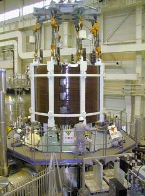
All four participants took part in the superconducting strand production, using different manufacturing techniques. All participants cabled their strand into the conductor. Jacketing was carried out by Europe and Russia, using material provided by the USA, and the model coil and test facility was manufactured, installed, and managed by Japan. Insert coils were provided for testing by Japan and Russia.
The Inner Module had an inner diameter of 1.8m, outer diameter of 2.7m and height of 2.8m. The Outer Module had an inner diameter of 2.7m, outer diameter of 3.6m and height of 2.8m. This module was very similar to one of the six of the ITERFEAT central solenoid, while the maximum field and the coil current were the same. About 25t of the strand was used to fabricate the inner module, the outer module and the insert coil. The parts were then assembled in the dedicated test facility at JAERI in Naka, as illustrated in Fig. 7.3.. The test facility was built as part of the ITER R&D activities. It consisted
of a vacuum system (a tank with 6.5 m diameter and 9.1m height) with a diffusion pump, a power supply system, a cryogenic system and a data acquisition system.
In Summer 2000, the CSMC was operated successfully up to the nominal current of 46kA corresponding to the generation of a maximum field of 13T with a magnetic stored energy of 640MJ with an inlet temperature of 4.5K. No coil quench occurred.
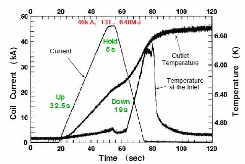
Fast discharge from 13T with a time constant of 8.5s corresponding to a field change of 1.5T/s was carried out successfully. All 38 conductor joints worked well within the design goals. This full charge was followed by a comprehensive test programme including current-sharing temperature measurements, AC loss measurements, fast ramp-up and fast discharges, and current and field cycles simulating the ITER CS operation. Figure 7.3.2.2 shows the temporal variation of coil current and temperature for a ramp-up and ramp-down cycle.
They all performed successfully without coil quenches. The CSMC and the CS insert coil were stable in pulsed operations with no sign of premature quench. The AC losses in the CSMC and in the CS insert were higher than expected at the first operation stage, but after several current cycles, they decreased to almost their expected values. Pulse operation had been experienced under more severe conditions than during ITER-FEAT operation.
To test the conductor, the CSMC would fit an "insert coil" within the bore of the main coil. A fullsize Nb3Sn conductor (~80m) could be accommodated with a bending radius of about 70cm. The CS insert coil was successfully tested with 10,000 cycles to simulate ITER operations (0–40kA cycles in the steady 13T background field of the CS model coil).
A single layer Toroidal Field Conductor Insert (TFCI) coil was manufactured by a collaboration of Russian scientific-industrial institutions and tested in the CSMC Test Facility at Naka in Autumn 2001. The manufacturing used the Nb3Sn strand with a thin-wall Ti jacket for a 45m length cablein-conduit conductor.
The TFCI was charged successfully, without training, in the background field of the CSMC to the design current of 46kA at 13T peak field. The insert met or exceeded all design objectives. It validated a thin conduit conductor in a grooved structure concept for ITER. Hydraulic characteristics, joint performance and hysteresis losses met or exceeded the design objectives. The TFCI also demonstrated the feasibility of Ti alloy as a conduit material for CICC[ 16]
The Poloidal Field Conductor Insert (PFCI), built jointly by the EU and RF, was the main full-size demonstration of the NbTi Cable-in-Conduit Conductor and joint technology that would be applied to the ITER PF coils. The PFCI was a single layer solenoid designed and built for extensive testing in Summer 2008 as a post-EDA R&D activity at the CSMC test facility in Naka.
The PFCI coil test achieved its main objectives, i.e. the establishment of a large database of experimental data relevant to the ITER PF coils. Most of the results matched closely the expectations. There was no sign of any training or fatigue effects. The coil performance at the nominal design current (45kA to 52kA) was not affected by the premature quenches observed on short cable samples. Accurate assessments of the AC loss of the conductor and joint were obtained during fast discharges confirming the acceptability from the point of view of heat removal. The coil was powered to conditions corresponding to an electromagnetic load 50% in excess of the design values without showing any sign of mechanical or electrical degradation in the following shots[ 17]
This section has been written using the following references: ITER Technical Basis, ITER EDA Documentation Series, no. 24, International Atomic Energy Agency, Vienna, Austria, 2002; Y. Shimomura, ITER Technology R&D, Fusion Engineering and Design Vol. 55, July 2001; N. Martovetsky et al., Test of the ITER TF Insert and Central Solenoid Model Coil, IEEE Transactions on Applied Superconductivity, Vol. 13, No. 2, June 2003; D. Bessette et al., Test Results from the PF Conductor Insert Coil and Implications for the ITER PF System, IEEE Transactions on Applied Superconductivity, Vol. 19, No. 3, July 2009.
The function of superconducting TF coils is to generate a magnetic field within the vessel of a tokamak. This field provides the primary mechanism of confinement of plasma particles.
The objective of the Toroidal Field Model Coil Project was to develop and demonstrate superconducting magnet technology to a level to provide enough confidence to build the ITER TF coils. Therefore, the tasks of the project included the validation of design and analysis, the demonstration of manufacturing capability, the correct performance of each component integrated in the magnet, the testing and the demonstration of reliable operation. The programme also drove the development of ITER full-scale conductor including strand, cable, conduit and terminations.
The TF Model Coil was a "race-track" shaped coil about 4m high and 3m wide, scaled with respect to the full-size ITER TF coils and including the key technical features and manufacturing approaches foreseen for the actual ITER TF coils. It consisted of:
• the conductor made of a Nb3Sn superconducting cable inserted into a stainless-steel jacket.
• the winding pack with the same layout as that of the ITER coils (but with a reduced number of conductor turns and pancakes). It consisted of pancakes of conductor supported by steel radial plates which, together with the coil case, provided the structural support to withstand both the in-plane and out-of-plane forces.
• the low resistance joints connecting each pair of adjacent pancakes.
• the insulation system (turn, inter pancake/radial plate and ground insulation).
The ITER TFMC consisted of five double pancakes (DP) of which the two outer DPs had one turn less than each of the other three. Each DP consisted of a radial plate with machined grooves on both sides in which the round conductor was placed. The conductor was formed from 1,080 strands, 720 of them were made of Nb3Sn and the remaining 360 were made of pure copper. The DPs were impregnated with epoxy resin, assembled and insulated to ground. The impregnated coil was placed in a welded stainless-steel case. The gap between coil and case was filled with insulation material but left a sliding surface between winding pack and case.
The size of the coil was selected so that it could interface with the existing Large Coil Task (LCT) background coil in a test configuration in the TOSKA facility at FZ Karlsruhe. The Large Coil Task (LCT), launched in the 1980’s, aimed at demonstrating the reliable operation of large superconducting toroidal field coils and at proving the design principles and fabrication techniques to be applied for the magnets in a tokamak power reactor. This was achieved through an international cooperation over more than ten years under an IEA agreement. Parties to the project were the US DOE, EURATOM, JAERI and the Swiss government.
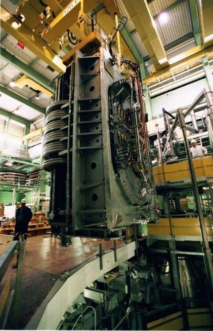
Six different D-shaped test coils were separately designed, developed and constructed by the LCT participants, then extensively tested in the years 1986-1987. The US provided three test coils, and the other three participants provided one coil each. Detailed information on coil design and manufacture and all test data was shared among the LCT participants. In addition to the planned tests to reach an 8T design point performance, the tests went well beyond by reaching 9T peak field in each coil. The arrangement of the TFMC allowed for testing of the conductor and the coil under various conditions. Figure 7.3.2.3 shows the insertion of the TF Model Coil into the TOSKA facility.
The TF model coil used a cable like the full-size TF coil cable. Although the coil diameter was smaller than the one of the ITER TF coils, the cross section was comparable to it. The conductor was tested for superconducting properties in the frame of the L-1 task.
In addition, two sections of the full-size case were manufactured, one by forging (inner leg) and one by casting (outer leg). The manufacturing of the TF coil case used both forged (30t) and cast (20t) pieces. Welding trials had demonstrated successful welding of the cast to forged sections and had established welding procedures for the case sections and the final closure weld of the half cases.
QA played a vital role in manufacturing. Several items had failed the initial quality control and had to be repaired or replaced. Therefore, in a few cases the manufacturing procedure was modified, and in all cases, a more stringent quality check was performed during fabrication. Such modifications led to an overall delay of 12 months in the original schedule.
The manufacture of the TF model coil was completed at the beginning of 2001.
The TF Model Coil was ramped up in July 2001 to the maximum current allowed by the facility of 80kA (see Figure 7.3.2.4), corresponding to a maximum field of nearly 8T (compared to 68kA and 11.8T, respectively in ITER).
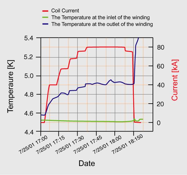
Fig. 7.3.2.4 Results of TF Model Coil tests
The tests in TOSKA also included operation with an additional background magnetic field produced by the LCT coil. In 2002, combined operation reached 80kA in the TFMC and 16kA in the LCT coil, generating peak electromechanical loads close to those expected in the full-size ITER TF coils (approximately 800kN/m).
The model coil was manufactured by Europe using Russian and European strand and US steel and Inconel structural materials and based on strand optimization carried out by all four participants. Although the design of the TF coil did not change substantially after the EDA years, the difference in size from the (1:3) TF Model Coil left some aspects still to be addressed, as, for example:
• how to manufacture radial plates with such a large dimension and such tight tolerances (in the TFMC the radial plate was manufactured from a single steel plate, this is not possible for the full size).
• how to wind the double-pancake on the 2 sides of the winding mould.
• how to transfer onto the 2 sides of the radial pate a double pancake wound in a single conductor length.
• how to reach such tight tolerance on the straight leg of the winding pack (0.5mm planarity over a 10m long straight leg)
This section has been written using the following references: T. Mizoguchi, “ITER technology R&D during the EDA,” Jul. 2001; ITER Technical Basis, ITER EDA Documentation Series, no. 24, International Atomic Energy Agency, Vienna, Austria, 2002; Y. Shimomura, ITER Technology R&D, Fusion Engineering and Design Vol. 55, July 2001; K. Ioki et al., “Convergence of design and fabrication methods for ITER vacuum vessel and in-vessel components,” in Proc. IAEA Fusion Energy Conference 2004, Vilamoura, Portugal, 2004[ 18]; K. Ioki et al., “ITER-FEAT vacuum vessel and blanket design features and implications for the R&D programme,” Nuclear Fusion, vol. 41, no. 3, pp. 309–321, Mar. 2001, doi: 10.1088/0029-5515/41/3/305[ 19]
The main purpose of the vacuum vessel (VV) sector project was to provide the input required to complete the design, especially regarding critical issues of fabrication technology such as
dimensional accuracy, welding distortions and achievable tolerances. The VV fabrication tolerances for the whole vessel, including field assembly, were specified to be less than ±20 mm for the total height and total width and ±5 mm for the sector wall thickness. The VV represented a significant step in size and complexity compared to past fusion vessels.
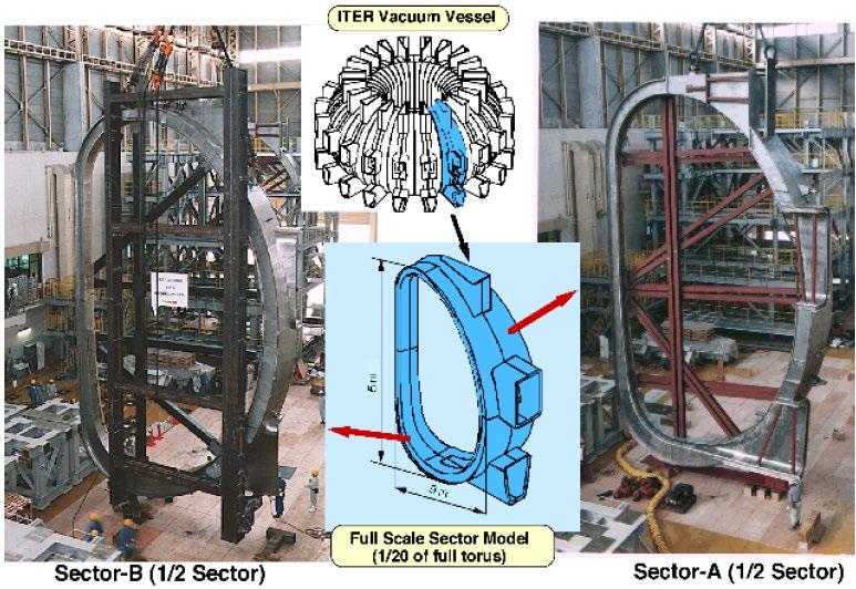
The aim of this project was the manufacturing, by the Japanese Home Team, of a full-scale sector model (sized for the larger 1998 ITER design) made of two 9o half sectors designated as sectors A and B (see Figure 7.3.2 5). Overall dimensions of the half sectors were 15m in height and 9m in width. The basic structure was a double wall design with the inner and outer shells made of welded plates, 40 to 60mm in thickness and separated by ribs which spaced the shells 0.45–0.83m apart. As a goal for the development, a dimensional accuracy of ±5 and ±4mm was specified for the sector model and the port extension, respectively. The design of these two half sectors was different to allow several fabrication methods to be investigated. For example, half sector A was poloidally segmented into nine parts during fabrication while half sector B was only segmented into four parts. The two segmentation schemes were intended to address the impact of poloidal segmentation on sector tolerances. The weld schemes for the two half sectors were also different.
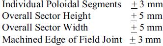
The technique selected for half sector A was tungsten inert gas (TIG) and electron beam (EB) welding while TIG and metal active gas (MAG) welding were selected for half sector B. Both half sectors were successfully fabricated. Both welding techniques and poloidal segmentation schemes showed to be feasible. The magnitude of welding distortions and achievable tolerances were determined. Overall achieved tolerances for the half sectors were less than ±5 mm for the half sector height and ±6 mm for half sector width (Figure 7.3.2.6). Non-destructive testing (NDT) including pressure testing, ultrasonic testing and radiographic testing was performed for only 10% of the welds and no defects were found. In addition, the pressure and leak tests were performed, and no pressure drop or leakage was detected. Mechanical testing of the sector model under gravity loading resulted in deformations that were less than predicted with a Finite Element an FE model.
In parallel, the Russian Federation Home Team manufactured a full-scale model equatorial port extension (Figure 7.3.2.7), developing and demonstrating fabrication technologies to the required specifications and tolerances and related inspection techniques and procedures. The port was attached to the vessel to simulate the field joint which would be made at the ITER site during the assembly of the machine. The US Home Team developed a fully remote welding/cutting system. An automatic ultrasound testing examination tool was developed to inspect the two parallel weld lines of the splice plates. The first demonstration test of automatic narrow gap TIG welding of the field joints between sectors was successfully completed at the end of May 1998[ 20]
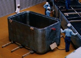
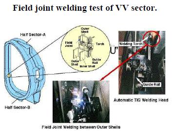
Figure 7.3.2.8 shows the tools used for the automatic welding between the outer shells of the vessel.
At that time, it was considered that the critical information related to fabrication technology including the magnitude of welding distortions and achievable tolerances gathered with this project were enough to validate the fundamental feasibility of the vacuum vessel double wall design. Additional R&D, such as the fabrication of a partial vacuum vessel sector model, was recommended as the first step to be done by the industrial firm chosen to manufacture this component. The sector was manufactured in Japan and assembled in Naka, with a mid-port extension provided by the RF, using welding and cutting techniques developed by the USA and Europe, and inspection methods developed by the RF.
This section has been written using the following references: T. Mizoguchi, “ITER technology R&D during the EDA,” Jul. 2001; ITER Technical Basis, ITER EDA Documentation Series, no. 24, International Atomic Energy Agency, Vienna, Austria, 2002; Y. Shimomura, ITER Technology R&D, Fusion Engineering and Design Vol. 55, July 2001; W. Daenner et al., “Progress of and future plans for the L-4 blanket project,” in Proc. IAEA Fusion Energy Conference 2000, paper IAEA-CN77/ITERP/18, 2001[ 21]
The main objectives of the L4 blanket module project were to:
• develop the technologies required for manufacturing the blanket.
• demonstrate the manufacturing feasibility by fabricating prototypes.
• demonstrate the ability of properly integrating them.
• demonstrate adequate operation of the components under relevant conditions.
A full-scale model of a shield blanket module was planned to be built to demonstrate the feasibility of its industrial fabrication.
At the start of the project, the need for modules with single and double curvature added a level of complexity. Therefore, alternative manufacturing routes were explored for the shield block. Solid and Powder Hot Isostatic Pressing (HIP) as well as casting were studied. The manufacture of small mock-ups showed that, while solid HIP provided good tolerances and bonding between steel surfaces, powder HIP required process improvements to avoid geometrical irregularities and deficiencies with respect to tolerances. Casting trials revealed degradation of mechanical properties and a high susceptibility to stress corrosion cracking. Therefore, this approach was not pursued.
The joining of the copper heat sink to the stainless steel was another important point of investigation. After having investigated brazing and bonding, eventually solid HIP was identified as the best choice to meet the stringent tolerances imposed by the primary first wall. Extensive development efforts were spent to identify the best parameters for the hipping process. Eventually, a HIP temperature specification of 1,040±10oC was recommended for industrial manufacturing.
The joining of CuCrZr to stainless steel was also widely studied. Mock-ups were manufactured and tested under thermal fatigue conditions. The results showed that the mock-ups exposed to four time the nominal heat load of 0.2MW/m2 or 1.5 times the peak heat load of 0.5MW/m2 survived the required 30,000 cycles without failure. The tests showed also that the joint was able to withstand for 1,000 cycles a heat load 10 times the nominal heat load.
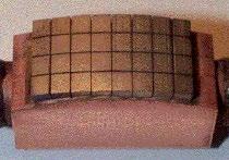
Fig.7.3.2.9 Fast amorphous CuInSnNi braze of small tiles at 800oC: mock-up resisted 1,000 cycles at ~12 MW/m2
The results of the R&D on Be/Cu alloy joint showed that, because of the difference in the thermal expansion coefficients of the two materials, the tile size had to be limited depending on the heat flux. Therefore, the beryllium was applied in the form of larger tiles for the primary first wall and smaller ones for the limiter and the baffle. The development of these Be/Cu joining techniques had to be verified through the manufacture and testing of mock-ups. Figure 7.3.2.9 shows a mock-up with brazed Be tiles.
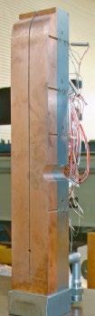
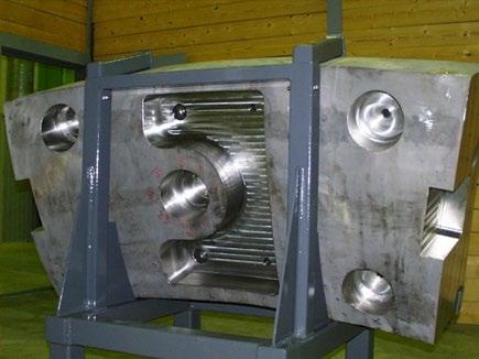
The Japanese Home Team had manufactured a full-size primary first wall module (Figure 7.3.2.11). The shield block was manufactured from a forged block. The FW copper heat sink was attached by HIPing. The module was successfully pressure tested. No defects were detected in the joints, and the tolerances were within the acceptable limits.
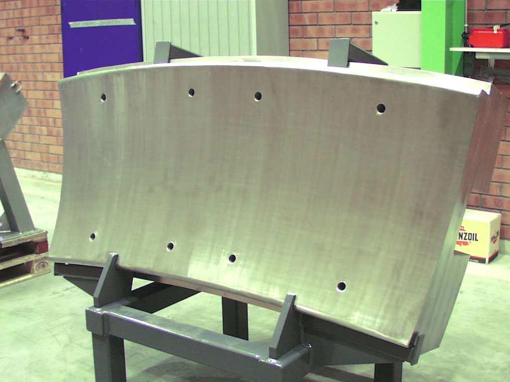
The EU HT manufactured a full-size shield block prototype by Powder HIP (Figure 7.3.2.12 and Figure 7.3.2.13). The shape of the shield block had then to be corrected, and the front and back surfaces had to be machined to the required dimensions. Some inaccuracies were outside the tolerance requirements, and the cause of this heterogeneity was identified. This approach for the fabrication was considered advantageous due to the improvement in the reliability of the components because of the lower amount of machining and welding and the minimization of the number of seal welds exposed to the vacuum.
Several prototypes of the titanium alloy cartridges, to be used for the mechanical attachment of the shield modules to the vacuum vessel, were manufactured in the Russian Federation and successfully tested (Figure 7.3.2.10).
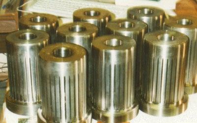
Fig.7.3.2.10. Flexible blanket module mechanical attachments made of Ti-Alloy.
All four participants worked together on the underlying work, with Europe doing the lion's share of the module manufacture and manufacturing the backplate. The work took place in the specialized laboratories, and components were tested in the high heat flux facilities of all four participants.
The integration of the modules into the supporting structures was also demonstrated and tested by the EU in a prototype assembly. Assembly tests also demonstrated the basic feasibility of installation and removal of a blanket module with mechanical attachments. A hydraulic, remotely driven bolting tool, which achieves high pre-loading using heating rods, was developed. Remote hydraulic connections through a 30mm penetration hole were also successfully performed, using a miniaturized YAG laser welding tool.
In the frame of the blanket R&D, innovative technologies were developed and existing technologies were improved, giving confidence in the feasibility and robustness of the chosen blanket design.
An evolution of the design was carried out with the ITER-FEAT modifications. A detailed design was developed for a shield block with radial flow cooling and four separable FW panels with two options for their attachment: (i) central beam and (ii) bolting with shear ribs. The intention was to result in significant cost and activated waste reductions compared to the 1998 ITER design. Fabrication methods for further cost reduction were covered through the additional R&D programme (see Section 7.3.3 Post EDA R&D) which investigated (a) the use of CuCrZr heat sink instead of DS Cu, (b) Be joining to Cu-alloy by brazing instead of solid HIPing, (c) powder-HIPed FW panels.
L5 – Divertor Cassette
This section has been written using the following references: W. Daenner et al., “Progress of and future plans for the L-4 blanket project,” in Proc. IAEA Fusion Energy Conference 2000, paper IAEACN-77/ITERP/18, 2001; N. Mitchell et al., “Design of the ITER magnets to provide plasma operational flexibility,” in Proc. IAEA Fusion Energy Conference 2004, Vilamoura, Portugal, 2004; F. Elio et al., “Design and development of the ITER blanket backplate flexible supports,” in Proc. 20th Symposium on Fusion Technology, Marseille, France, 1998.
The main objectives of the divertor cassette project were to:
• demonstrate the feasibility to manufacture components capable of withstanding the high heat fluxes set for the divertor: 1,000 cycles at 10MW/m2 and 100 cycles at20 MW/m2
• demonstrate the reliability of the joints between armour and heat sink.
• show that the cassettes can be assembled to the demanded high tolerances (±1mm).
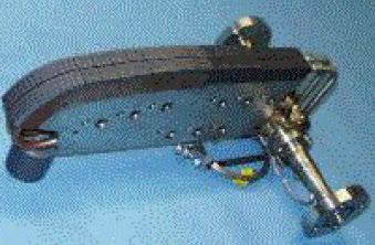
and W
The efforts focused on carbon fibre composite (CfC) for the lower part of the vertical target (suitable for the 10–20MW/m2 heat flux) Figure 7.3.2.14). Tungsten was selected for the upper part of the vertical target due to its low sputter yield. The most critical aspect of a plasma facing component (PFC) was the armour-to-heat-sink joint and the EDA R&D had seen good progress made in the development of both CfC to Cu and tungsten to Cu joints. The CfC monoblock was shown to be a robust design for the CfC armour, and in tests a prototype had survived 2,000 cycles at 20MW/m2. It was preferred over the less expensive flat tile design, because of concerns over the observed tendency for flat tiles to suddenly and totally detach. For the upper part of the target, 10x10x10mm tungsten tiles, with a pure Cu layer cast onto the tungsten to accommodate the differential thermal expansion of tungsten to copper, were brazed to a CuCrZr alloy rectangular hollow section, a design that sustained > 20MW/m2 for 2,000 cycles in HHF testing.
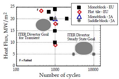
Figure 7.3.2.15 shows the results of high heat flux tests of the small and medium scale CfC/Cu mock-ups.
Fig. 7.3.2.15. Results of high heat flux tests of the small and medium scale CfC/Cu mock-ups with Ag-free brazing alloys.
The project was able to develop the technology needed to build full-scale components with adequate armour, armour-heat sink joint (CfC-Cu & W-Cu), and heat sink lifetime, and sustaining thermo-hydraulic and electro-mechanical loads, whilst utilizing the most cost effective and reliable manufacturing processes.
Major issues included the bonding of different plasma facing materials on the same component, the selection of the heat sink material (CuCrZr preferred), and the demonstration that it maintained its properties after manufacturing. The CfC monoblock proved to be able to meet the ITER requirements reliably and with no complete detachment of tiles.
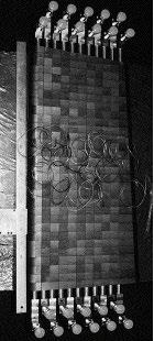
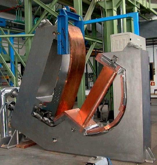
High heat cycle tests showed that CfC monoblock survived 20MW/m2 for 2,000 cycles (EU) and tungsten (W) armours survived 15MW/m2 for 1,000 cycles (EU/RF). A large divertor target mockup with CfC attached to dispersion-strengthened copper (DSCu) through oxygen-free copper (OFCu) was successfully tested under 20 MW/m2 over 1,000 cycles from a large hydrogen ion beam with a diameter of 40cm (JA) (Figure 7.3.2.16).
Irradiation tests were also performed. For example, CfC brazed on Cu survived 20MW/m2 for 1,000 cycles after 0.3dpa irradiation at 320°C. Tests with pulse heat deposition simulating the thermal load due to disruptions demonstrated erosion but no disruptive failure of CfC armours even with 0.4dpa irradiation.
Tungsten brush type armour proved to be a solution to having a Cu-W joint able to withstand the large difference in thermal expansion of the two materials under the high heat flux loads.
Aside from testing component designs, one of the main aims of the L-5 project was to integrate key plasma facing components together onto a realistic prototype of the cassette body. The EU constructed an integration prototype (Figure 7.3.2.17 and Figure 7.3.2.18). It was not essential to use all the real materials for these prototypes, and dummy components were made thermo-
hydraulically equivalent to the real components. In addition, parts of full-size prototypes of the components were tested in high heat flux tested.
Construction of the cassette body both from steel castings and from forged steel plates were considered. R&D showed that either approach had the capability to produce a robust vacuum-compatible component. However, cast 316LN material had ~ 30% lower yield strength than forged material, and hence fabrication from forged steel was preferred, as it allowed the cassette thickness capable of sustaining the electromagnetic loads to be ~50mm thinner in the critical region beneath the inner divertor channel, a thickness that could be allocated to the inner channel depth.
As for the PFC attachment to the cassette body, analytical assessments indicated that the attachments could carry the currents flowing between the PFCs and the cassette body during disruptions or VDEs. Preliminary R&D performed in air simulating the electrical and mechanical loads and the applied joint rotation showed no joint degradation and indicated that separate earth straps are unnecessary.
For research activities to be carried out in the following years, it was considered that R&D in operating machines would have provided results on which an optimized material choice could be based before manufacturing started, to be confirmed by initial experimentation in ITER (during the H phase). It was assumed that, if needed, the divertor PFCs in the cassettes could readily be replaced to provide different geometry and/or different plasma-facing material.
All four parties contributed to this development.
This section has been written using the following references: W. Daenner et al., “Progress of and future plans for the L-4 blanket project,” in Proc. IAEA Fusion Energy Conference 2000, paper IAEACN-77/ITERP/18, 2001; N. Mitchell et al., “Design of the ITER magnets to provide plasma operational flexibility,” in Proc. IAEA Fusion Energy Conference 2004, Vilamoura, Portugal, 2004; F. Elio et al., “Design and development of the ITER blanket backplate flexible supports,” in Proc. 20th Symposium on Fusion Technology, Marseille, France, 1998.
The most critical issues for the blanket module replacement are the positioning, the attachment to the vacuum vessel, and the transport of the modules with high reliability and accuracy within the confined space of the vacuum vessel and maintenance ports. It was, therefore, essential to Fig. 7.3.2.18 Inboard divertor channel integration mock-up flow test.
demonstrate the feasibility of the module replacement using a full-scale mock-up. The main objective of the Blanket Module Remote Handling (RH) project was therefore to develop and demonstrate the ability to remotely maintain blanket modules, including manipulating a 4t module at a distance of 8m with an accuracy of ± 2 mm.
A reduced capacity rail-mounted vehicle/manipulator system for a payload of 1.2t and a partial model of the rail deployment system were first built and tested to verify the handling capacity and positioning accuracy of the manipulator together with the deployment procedures of the articulated rail system. Development of the associated auxiliary equipment and tools (i.e. welding/cutting tools for cooling pipe connection/disconnection, transfer casks with double seal doors for contamination control) were also part of the project.
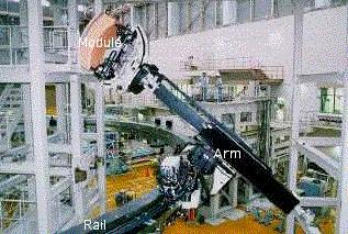
Model module replacement operations were performed using the manipulator in a teachrepeat mode. The results showed high repeatability of operations within a 0.5mm tolerance in all directions.
A new sensor-based position control system was developed and installed on the vehicle. The test results showed that an initial positioning error of up to 30mm could be automatically compensated within an ultimate positioning accuracy of less than 0.5mm and 0.1o using the position feedback control. Tests also showed that the rail could be deployed 90o around the torus in about 30 minutes. After development and prototype demonstration of the main systems and techniques, full-scale testing and verification were successfully completed in 1998 on the Blanket Test Platform (BTP) constructed at the Naka laboratory (Figure 7.3.2.19 and Figure 7.3.2.20). The test platform included module handling equipment, port handling equipment, auxiliary remote handling tools and a blanket mock-up structure to reproduce the physical environment of a 180o ITER in-vessel region. A suppression control system to reduce dynamic deflection and vibration of the arm to negligible levels was developed and successfully tested.
The trials confirmed that, during rail deployment, the guidance and docking mechanisms at the 90o and 180o ports were capable of guiding the deflected rail to the correct position and then fix it to form the required rigid ring structure. The operation time for the deployment and storage
was about two days and above the target (one day). Optimization of the procedures was deemed necessary.
Module replacement and transfer tests were successfully performed automatically using teach and repeat control. The positioning error and deflection of the manipulator were measured during the replacement and transfer operations. The repeatability of the measured position accuracy was about 1mm and therefore it satisfied the 2mm accuracy required by ITER for module installation. However, the larger than expected deflections when the module dead weight was transferred to the manipulator during module removal, required the development of a new control scheme. The basic performance required for module replacement was demonstrated and optimization of procedures and control were identified.
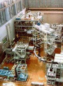
The blanket in the ITER machine requires very precise positioning (± 0.25mm) with respect to keys and pins. Successful module insertion tests were carried out to check the ability to handle misalignments between modules and keys during installation. A full-scale transfer cask with a double seal door was manufactured to verify the guiding positioning system during docking and the leak tightness of the seals between the two docking interfaces. The results of the tests were successful, and they demonstrated a good margin over the given requirements.
The cooling pipes of the module had to be cut and rewelded from the inside of the pipe on account of space constraints. Therefore, suitable tools had to be developed. A YAG laser beam was adopted for welding and cutting method due to its structural flexibility. In addition, bore tools for weld inspection and manifold welding/cutting were manufactured and tested.
As RH tools are required to have sufficient radiation hardening to allow working for a sufficient time under intense gamma radiation, both JA and EU HTs conducted extensive gamma ray irradiation tests and developed components that provide a radiation hardness of 10–100MGy at a dose rate of about 10kGy/h.
L7 – Divertor RH
This section has been written using the following references; W. Daenner et al., “Progress of and future plans for the L-4 blanket project,” in Proc. IAEA Fusion Energy Conference 2000, paper IAEA-
CN-77/ITERP/18, 2001; N. Mitchell et al., “Design of the ITER magnets to provide plasma operational flexibility,” in Proc. IAEA Fusion Energy Conference 2004, Vilamoura, Portugal, 2004; F. Elio et al., “Design and development of the ITER blanket backplate flexible supports,” in Proc. 20th Symposium on Fusion Technology, Marseille, France, 1998.
The objective of the Divertor Remote Handling project was to demonstrate that the following operations are feasible:
• replacing and refurbishing all components several times during the machine life.
• replacing and refurbishing single faulty components.
• positioning high heat flux components so the maximum step between those on adjacent cassettes would be under 4mm and the maximum variation around the whole torus would be within ±10mm.
• locking and securing the supports, making water pipe connections, assembling electrical connectors, and handling port plugs.
• replacing all cassettes in less than six months and replacing a single cassette in under eight weeks.
Two test facilities the Divertor Test Platform (DTP-Figure 7.3.2.21) and the Divertor Refurbishment Platform (DRP-Figure 7.3.2.22) were built at the ENEA Research Centre of Brasimone (Italy).
The system was based on a toroidal transporter that moves a cassette in front of a remote handling port from where the cassette was extracted with a radial mover that was deployed from a transfer cask docked to the port.
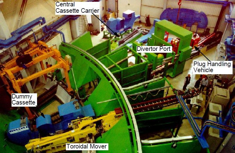
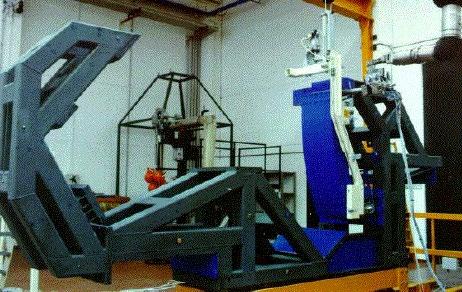
The DTP was used to simulate, at full scale, all handling operations inside the vacuum vessel, including removal and replacement through vessel ports. It reproduced the geometrical environment of a 72o section of the lower part of the ITER 1998 vacuum vessel with four access ducts. It included the necessary models, prototypes and mock-ups (i.e. divertor maintenance mock-ups, reactor models, mover prototypes, auxiliary RH equipment prototypes). An integrated supervisory control and data acquisition system was used to monitor and control this equipment.
The key elements of the maintenance procedure were as follows: radial insertion of the cassette from the chamber using radial movers; toroidal manoeuvring using toroidal mover; lowering of cassette into position on wheeled and jacking forks; remote attachment to rail. Specialized movers ("cassette carriers") were used to install the central cassette and one adjacent cassette.
After having carried out a basic demonstration of the feasibility of divertor handling, work focused on the facility to optimize operations procedures, to increase the degree of automation and to improve the man-machine interface.
The operational experience with the DTP confirmed the following results:
• cassette in-vessel positioning could be achieved with an accuracy of better than 1mm.
• during the locking operation the cassette position could be corrected from initial errors up to 4mm inboard and 8mm outboard.
• after locking the repeatability of the cassette position in the vacuum vessel was better than 0.2mm.
• the cassette toroidal mover was able to cope with misalignments up to 10mm and able to accommodate horizontal gaps and vertical steps between adjacent rails of up to 2mm.
• all radial movers were able to carry out their tasks.
All these results fully satisfied and, in some cases, significantly exceeded the specified requirements.
Certain improvements were investigated to reduce costs and to implement lessons learnt in the early tests to improve man-machine interface, sensors, and time, as well as to improve sliding components and to investigate rescue scenarios if components become jammed.
In parallel, the development and qualification of a bore tooling system for the cutting/welding and weld inspection of the radial divertor cooling pipes was carried out. A suitable tool was developed and tested. Interchangeable tool heads could be inserted and positioned with an accuracy of 0.5mm to perform the operations. Trials showed that cutting operations on a 6-inch schedule of 40 pipe would take approximately 3 hours. The welding and weld inspection operation could be completed in about four hours. The evolution to the ITER FEAT design required an upgrade of the tool to be able to cope with bent pipes. A prototype was developed for a 4in pipe diameter with a 400mm minimum bend radius.
The DRP was built to simulate the most critical operations to be undertaken in the Hot Cell. The assembly and disassembly of high heat flux components (HHFCs) was simulated with prototype tools. Only those parts of the mock-up which were critical for HHFC mounting were machined accurately. Tests showed that the remote measurement system could be operated accurately enough (0.01mm) and that components could be correctly machined to fit. A target mock-up was installed on the cassette with the required accuracy.
Following several refurbishment test campaigns involving improvements, the critical insertion and extraction operations could be achieved under fully remote conditions. Some frequent jamming could be overcome by the development of a complex system of sensors to ensure an exact key to keyway alignment during the operation. An alternative approach (i.e. the use of internally expanded hollow link-pins) was successfully tested without the need of sophisticated operator assistance.
Key elements such as motor, position sensor, wire/cable, glass lens, electrical insulator, periscope and strain gauge showed to survive tests at 106–107Gy.
Further work was identified to streamline procedures to shorten the time taken.
The L-7 project was jointly performed by the European and Japanese Home Teams.
In addition to the seven large R&D projects, development of components for magnets, fuelling , pumping, tritium processing, heating and current drive, power supplies and plasma diagnostics, as well as safety-related R&D, significantly progressed.
Magnets
This section has been written using the following references: Y. Shimomura, ITER Technology R&D, Fusion Engineering and Design Vol. 55, July 2001; N. Mitchell et al., “Design of the ITER magnets to provide plasma operational flexibility,” in Proc. IAEA Fusion Energy Conference 2004, Vilamoura, Portugal, 2004[ 22] .
For the magnet system power supplies, mechanical bypass switches and fast-make switches were developed and successfully tested at 66kA, and explosively actuated circuit breakers were developed and successfully texted at 66kA and 170kA at the Efremov Institute (RF).
As for the magnets, following the adoption of the new ITER FEAT configuration, new R&D activities were identified to improve the database, allow cost reductions and address technological needs specific to the updated ITER design. They covered the insulation materials and shear keys, the precompression rings of the TF coil structure, the radial plate manufacture, the materials and manufacturing technology database for the jacket of the CS conductor, and the CS pancake joint performance. An R&D programme on NbTi conductors and joints for the PF coils was also launched and results had already been obtained on investigations of strand coatings for AC loss control. Testing of conductor and joint samples were planned. The manufacture of a NbTi insert coil was an essential part of this programme. The design of this NbTi insert coil was planned to be manufactured and testing was scheduled to start at Naka test facility in 2003.
Mechanical R&D for the coils consisted of the characterization of cryogenic steels, welding development and fabrication of large representative forged sections. Major items were successfully completed before 2001, but characterization and welding development continued in the following time. The results led to a redefinition of the property requirements of the TF structures since 2001, subdividing the material into three grades depending on the location, minimizing the quantity of the highest (and most expensive) grade with guaranteed yield stress >10,00MPa at 4K to 25% of the total weight of 207t. The lowest grade 3 required a guaranteed yield stress >750MPa at 4K and made up 45% of the weight.
Assessment of the Nb3Sn cable performance from the two model coils tasks (CSMC-L1 and TFMCL2) showed some discrepancies from those expected based on the performance of isolated Nb3Sn strands. This appeared to be associated with transverse mechanical loads on the conductors (up to 40t/m). Additional testing was carried out to quantify the effect and the following results from EPFL-PSI are shown in Figure 7.3.2.23.
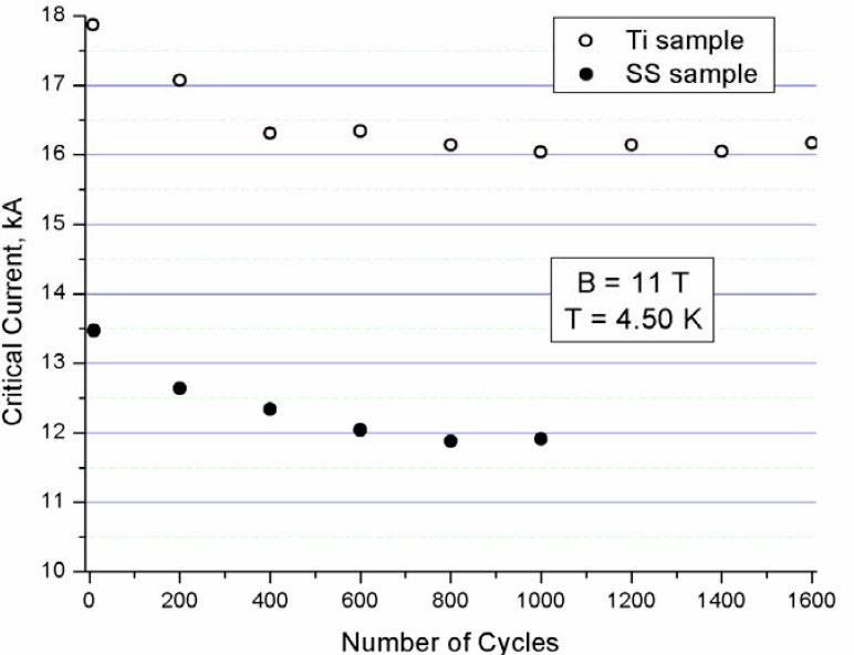
Fig. 7.3.2.23 Behaviour of Nb3Sn strands in a (subsize, one sixth scale) cable, showing initial performance drop in critical current probably caused by cable settlement. The cable is identical, with either a steel or Ti jacket producing different thermal strain on the strands (difference equivalent to about 0.1 to 0.15% strain).
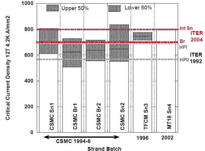
Fig. 7.3.2.24 Improvements in strand performance during/since Model Coil construction, range of critical current compared to specification (HPI and HPII are the original bronze/ internal tin specification, Br is bronze route, Sn is internal tin, MT18 is a published reference).
Nb3Sn strands could show progressive filament fracture under overall tension and to avoid this risk, a steel conductor jacket was chosen as the reference (instead of Ti). This created overall compression due to differential contraction, but the compression also resulted in lower strand performance. The performance drop required some increase in temperature margin. This was obtained without increasing the cable dimensions by taking advantage of improvements in the technology of Nb3Sn strand production which had increased the critical current by over 20% compared to what was available at the start of the model coil procurement (see Figure 7.3.2.24).
This section has been written using the following references: F. Elio et al., “Design and development of the ITER blanket backplate flexible supports,” in Proc. 20th Symposium on Fusion Technology, Marseille, France, 1998[ 23]
The design foresaw that blanket modules were mounted on a structural shell (the backplate”). The backplate supports would have to withstand vertical and horizontal electromagnetic forces up to 80MN, while allowing relative thermal expansion during operation, baking and upset conditions. Mock-ups and a full-scale support prototype were built with AISI 316 stainless steel. Cooling passages were obtained by deep drilling. Electron beam welding was selected to join the plates to the flanges.
Experimental tests were carried out on specimens, single plates and on a whole support to qualify the design and to check the load carrying capability of the support with respect to buckling. A special rig was designed and manufactured to perform 3-axis load tests reproducing the full restraint on the flanges. The performance of flexible supports in non-linear conditions was assessed experimentally. Yielding reduced their load capacity but there was an adequate operating margin. The manufacturing route was also proven.
This section has been written using the following reference: S. Tanaka, M. Nishikawa, Y. Ichimasa, and M. Nishi, “Activities of tritium studies in Japan,” Fusion Science and Technology, vol. 41, no. 3, pp. 305–312, 2002, doi: 10.13182/FST02-A22602
A tritium pellet injector was tested with a throughput of 36g T2 and 28g DT, and ejection of a large pellet (10mm) from an 80cm radius curved guide tube was successfully achieved at 285m/s in the US. A fully integrated fuel cycle system was tested in the US using about 100g of tritium throughput under various operation conditions, including 25 days of around-the-clock operation.
This section has been written using the following reference: S. Tanaka, M. Nishikawa, Y. Ichimasa, and M. Nishi, “Activities of tritium studies in Japan,” Fusion Science and Technology, vol. 41, no. 3, pp. 305–312, 2002, doi: 10.13182/FST02-A22602; C. Day et al., “Validated design of the ITER main vacuum pumping systems,” in Proc. IAEA Fusion Energy Conference 2004, Vilamoura, Portugal, 2004[ 24]
A half-scale cryogenic pump for DT, He and impurities was completed and was tested in the EU (Figure 7.3.2.25).
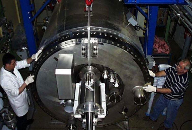
Fig. 7.3.2.25 50% Scale Cryogenic Pump (EU).
In the TIMO test bed at FZK, the model pump went under an extensive and fundamental investigation, studying pumping, regeneration (thermal desorption pattern) and cryogenic aspects (heat load assessment, LOVA).
The model pump cryosorbing panel area, originating from the required helium pump capacity, was composed of several identical cryopanels with a design that was similar for all ITER primary cryopumps.
Tab. lists some of the model pump design details and compares them with the corresponding values of the ITER 1:1 pump.
Tab.7.3.2.1 Design features of the TIMO model pump and the ITER 1:1 pump.
Cryopanel system (coated both sides)
4 m2 (16 panels, 0.85 m long x 0.15 m wide)
11.2 m2 (28 panels, 1 m long x 0.2 m wide)
Pump volume (m3) 1 (closed housing) 7 (nude style)
Major R&D contributions on tritium handling and processing technology for ITER came from the EU[ 25], from Japan[ 26] and from the US[ 27] participating teams. Russia [ 28] was active as well, and Canada[ 29] was interested in developing fusion technology mainly because of the kilogram amounts of tritium available from CANDU reactor heavy water processing, potentially being used for operation of ITER, and for start of power reactors before the latter would become selfsufficient.
The ability to safely handle tritium is key in experimental R&D on tritium processing technologies for nuclear fusion. Chemical isotope effects are rarely below 0.5 or above 2.0[ 30] if expressed as ratio of characteristic constants such as diffusion coefficients or solubilities. However, radiochemical effects and isotope exchange reactions, e.g. with the intrinsic hydrogen present in virtually all materials, can neither be investigated using simply deuterium nor just tritium as tracer but require usage of tritium at fusion relevant concentrations, i.e. 50% of total hydrogen or higher. Mathematical modelling of isotope effects or radiochemical reactions are of limited value without experimental data from tritium R&D. An example is the inverse isotope effects of hydrogen, deuterium and tritium diffusion in palladium, where the heaviest isotope has lowest solubility and highest diffusivity. This effect can well be explained; however it would have hardly been predicted through modelling, let alone being quantified.
Developments and tests of components at ITER relevant tritium concentrations and scales require at least a few ten grams of tritium. Any matching R&D facility therefore needs considerable infrastructure, above all for tritium confinement, for tritium material management and control, for radiological monitoring, and for effective control of effluents and releases. Multi-million-dollar investments have therefore been made to establish tritium facilities around the world by the end of the eighties to the middle of the nineties of the last century. In the US the Tritium Systems Test Assembly (TSTA) in Los Alamos (NM) was functional between 1984 and 2001. Japan’s Tritium Processing Laboratory (TPL) in Tokai became actively operational in 1988. The Tritium Laboratory Karlsruhe (TLK) in Germany was licensed in 1993 and is still in use. JET (UK) installed an Active Gas Handling System (AGHS) and introduced tritium into the machine through neutral beam injectors in 1991 for the first time. TFTR used tritium between 1993 and 1997.
TSTA, TPL and TLK listed
• development of nuclear fusion exhaust fuel clean-up technology,
• testing and qualification of prototype components such as vacuum and transfer pumps, permeators, catalyst reactors, storage getter beds, valves, cryo-traps, fueling devices,
• provision of a reliable data basis for tritium handling components,
• process development for the recovery of tritium from breeding blankets,
• work on the development of process analytics, tritium material control and accountancy,
• studies on tritium material interactions and radiochemistry,
• development of advanced safety for personnel and environmental protection,
as main objectives, overarching and quite challenging. An important but not explicitly mentioned aspect was education of chemical engineers and scientists through hands on working with tritium at fusion relevant concentrations and amounts. The concealed competition between the three laboratories was eventually to the benefit of the development of fusion technology, R&D results to a large extent complementary.
TSTA operated an integrated tritium processing loop[ 31] shown in Figure 7.3.2 26, employing depleted uranium getter beds for storage, and atmosphere detritiation based on catalytic oxidation followed by trapping of tritiated water on zeolites. Not shown in the diagram is an emergency room air detritiation system, twice used to clean-up the 3000 m3 main hall from 3.7*1010 Bq each time, released on purpose to support mathematical modelling on atmosphere detritiation[ 32]
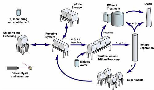
The TSTA flagship was a four-column cryogenic isotope separation system [ 33], successfully tested with tritium at inventories of around 100 g. The system response to an unscheduled loss of refrigerant accident was completely as expected, hydrogen isotopes safely recovered, and operation restored after repair of the cryogenic system within only one week.
The TLK infrastructure provides a closed loop for tritium experiments [ 34]. Gas supply to experiments is either through secondary confined pipe work or using sample bottles. Tritiated impurities are processed, recovered hydrogen isotopes transferred to isotope separation based on palladium displacement chromatography, and pure tritium is stored on depleted uranium getter beds.
TLK R&D activities focused on tokamak exhaust processing, using the CAPRICE facility to develop tritium and deuterium removal and off-gas clean-up technologies based on combination of heterogeneously catalyzed reactions with specific permeation of hydrogen isotopes through palladium / silver membranes[ 35]. The facility initially had a throughput of 1/8th of ITER scale.
However, with increasing fueling requirements the scaling factor was significantly reduced. Also, the ITER requirements on detritiation factors increased, and an additional process step, i.e. counter current isotopic swamping, was introduced; the new concept was called CAPER[ 36]. The CAPER facility is still operational and part of the closed tritium loop at TLK[ 37]. Figure 7.3.2 27 shows parts of the glove boxes of the CAPER facility.
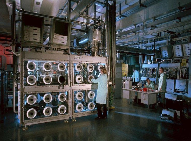
Other main activities related to fusion at TLK concerned testing of zirconium-cobalt for tritium storage, development of analytical techniques such as gas chromatography and LASER Raman spectroscopy, and tritium accountancy through calorimetry[ 38]
At TPL the R&D activities concentrated on development of storage materials [ 39]. Getter beds based on zirconium-cobalt alloy as a potential alternative to depleted uranium have been investigated, also for transportation purposes. A 25 g tritium transport bed was built, licensed in Japan, in Canada and in the US as a BU type transport package[ 40], and used for shipment. Emphasis was also on atmosphere detritiation and safety[ 41],[ 42], and on tritium extraction and removal from breeding blankets[ 43]. An exhaust clean-up process based on high temperature electrolysis has been developed and tested with tritium at TSTA within a Japan / US collaboration agreement [ 44]
TPL also looked into tritium material interactions, and among others mixed tritium with carbon monoxide [ 45]. The immediate observation by eye was production of white fog. Tritiated aldehydes, tritiated alcohols, and tritiated carboxylic acids were found in the solid phase, and tritiated water and tritiated methane in the gas phase. The radiochemistry between tritium and carbon is
complex, and any contact between these two materials in fusion devices shall be avoided to the extent possible.
JET[ 46] and TFTR[ 47] added essential experience to tritium handling in tokamaks. Above all the interaction between tritium and the carbon first wall cladding[ 48] was found to produce notable amounts of so-called carbon co-deposits, un-stoichiometric solid carbon / tritium compounds[ 49]
This has eventually led to excluding carbon as first wall in fusion devices using tritium.
Based on R&D results the tritium plant systems have been designed and documented in the FDR for ITER FEAT in 2001; the activity was led by the EU participating team. An integrated flow diagram became available for the first time, and PFD’s and P&IDs have been prepared for the different tritium processing systems. Canada provided the design of the cryogenic isotope separation system.
In summary, R&D on tritium handling and processing for nuclear fusion has been ongoing since more than forty years. An early start of the work was needed for design of the fusion fuel cycle, and above all to pave the road for the licensing of ITER. Ironically, the procurement sharing did not mirror the experience gained in the participating teams: Tokamak exhaust processing was assigned to the US after they had rejoined, and isotope separation was assigned to the EU.
This section has been written using the following reference: S. Tanaka, M. Nishikawa, Y. Ichimasa, and M. Nishi, “Activities of tritium studies in Japan,” Fusion Science and Technology, vol. 41, no. 3, pp. 305–312, 2002, doi: 10.13182/FST02-A22602
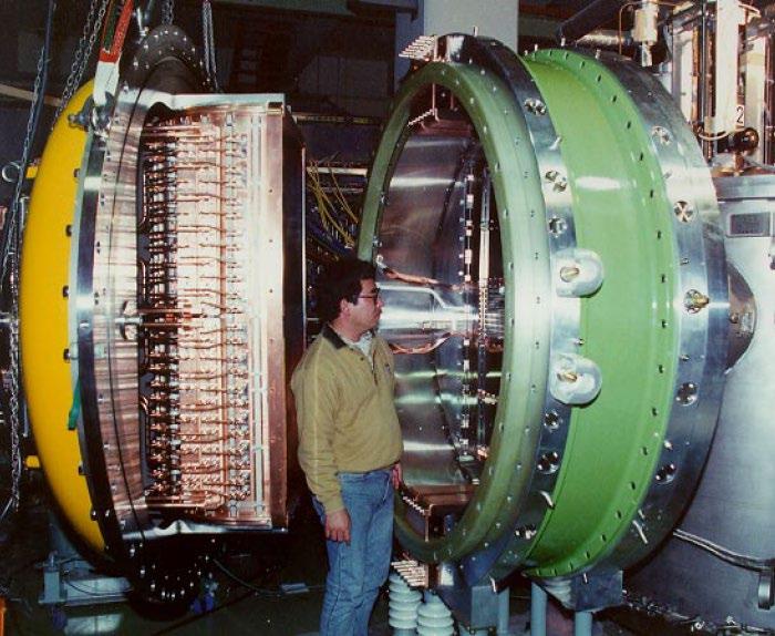
Gyrotrons at 170GHz were developed and successfully operated in JA at 0.9MW x 9s with a chemical vapour deposited diamond window from the EU, and at 1MW x 1s in the RF.
Key components for the ion cyclotron plasma heating antenna and the transmission line were developed and tested at a higher voltage than the expected operational voltage.
Although there was no "near full-size" beam source developed specifically for ITER, good results were achieved. In Japan, a 500keV beam source has been operated on JT-60 and high voltage acceleration technology (1MeV, though it operated at reduced current) was developed (Figure 7.3.2.28).
This section has been written using the following reference: S. Tanaka, M. Nishikawa, Y. Ichimasa, and M. Nishi, “Activities of tritium studies in Japan,” Fusion Science and Technology, vol. 41, no. 3, pp. 305–312, 2002, doi: 10.13182/FST02-A22602
During the EDA the ITPA Diagnostics Group (ITPADG), the successor of the Diagnostics Expert Group, managed the generic R&D being carried out for Diagnostics with participation by all the ITER partners. Much of this work is still continuing [ 50]. The ITPADG was effective in encouraging and coordinating R&D across all the DAs, and also arranged for significant testing with operating tokamaks. Its primary focus lay in two areas.
The first was in seeking new measurement techniques, necessary either because of the limitations of some then-current techniques because of the ITER size and environment, or specific needs for the very long pulse lengths such as measurement of surface erosion of the first wall and dust accumulation. Many studies, often not finally applicable, are reported [ 51]. A significant effort was also expanded on the impact on optical diagnostics of a highly reflective first wall made of beryllium. The challenge of the calibration of the neutron measurement systems was addressed.
But the main concentration remained on the issues raised by operations in the high neutron and gamma fluxes and fluences for the components closest to the plasma. For ITER diagnostics the biggest issues are due to flux in real time, fluence becoming dominant for a fusion reactor and the very high temperatures. Generic problems for insulators, mirrors and windows had to be resolved.
A major concern was to begin the process of selecting and qualifying mineral insulated (MI) coaxial cables, not only necessary for the magnetic diagnostics themselves, but also for carrying electrical signals to the feedthroughs in the walls of the vacuum vessel. During pioneering studies, it became apparent that a voltage along the central conductor can be generated due to radiation-induced electromotive force (RIEMF) and by radiation-induced thermo-electric sensitivity (RITES), which could complicate interpreting the signals51. A few materials and sizes have been tested for the central conductor, the insulator and the outer metal sheath, but during the EDA there was a limited availability of different MI cables. It is apparent that steels or Inconel are preferable to copper for the inner conductor. Some odd results have been obtained so far in the RIEMF studies
which may be explained by lack of coaxial symmetry in the manufactured MI cable[ 52], implying a need for tighter manufacturing controls. An associated study of a radiation-induced issue is that of the electrical feedthroughs carrying the signals out of the vacuum vessel. Here, the issue is radiation induced conductivity (RIC).
A large fraction of all the diagnostic techniques makes use of light in the visible wavelength range, so systems for transferring the light from the plasma to the detector system in a high radiation environment needed an optical labyrinth to replace the optical fibers, used in previous tokamaks. Hence first mirrors facing the plasma had to be investigated for their performance under radiation and their ability to withstand bombardment from high energy particles leaving the plasma and deposition of material from the plasma. They must also maintain their shape at the high temperatures they will experience. Studies of single crystal molybdenum, and tungsten and polycrystalline mirrors have been carried out 51 with tests on many devices including JET [ 53]. This ongoing programme will also examine materials for the substrates and potential cleaning techniques.
Windows of many different materials and sizes are needed for the different wide-wavelengthrange signal transmissions through the vacuum wall51. These must meet stringent specifications since they form part of the first tritium boundary. The windows are double layer and must be thick enough to withstand the specified potential accident conditions. Various window materials have been tested under fission sources. Windows made of diamond is a newly available technology and is being considered for use.
As new physics and technology information has become available, the R&D programme for diagnostics has continued since the EDA50. More details of the post-EDA R&D activities can be found in Vol. 2.
This section has been written using the following reference: S. Tanaka, M. Nishikawa, Y. Ichimasa, and M. Nishi, “Activities of tritium studies in Japan,” Fusion Science and Technology, vol. 41, no. 3, pp. 305–312, 2002, doi: 10.13182/FST02-A22602.
Safety-related R&D, such as the characterization of dust in tokamaks, tritium co-deposited with carbon, and experiments on steam-material reactions, provided inputs for key phenomena and data for safety assessments. R&D emphasis was on the verification and validation of data, models and computer codes. Neutron shielding tests using 14MeV neutron sources in JA and the EU demonstrated that the accuracy of activation calculations was within 10%.
At the end of the EDA some R&D activities launched in the 1990s had not been completed yet. As seen above, some of the components in the large R&D projects have just completed their construction and tests campaigns were starting. In some other cases, the evaluation of the results from previous R&D tasks had given some food for thoughts to the ITER engineers and therefore additional activities were launched for improving the design, removing unpracticable solutions and exploring, where necessary, new approaches also due to the most recent results from the existing experiments[ 54] .
The information on the post-EDA R&D activities for the different areas will be expanded and completed in Vol. 2.
Magnets
Pre-compression Rings
As a consequence of the design modifications introduced in the ITER FEAT configuration, in order to cope with the out-of-plane forces, six pre-compression rings (three at the top and three at the bottom) were introduced to pre-load the poloidal keys at the top and bottom of the inner straight leg of the toroidal field coils with a centripetal force and therefore to suppress any gap opening and to reduce any cyclic fatigue stresses.
A first study carried out at ENEA Frascati (Italy) identified an S2 glass-fiber/epoxy composite as the most suitable material. During the manufacture emphasis would have to be placed on obtaining a structure with a very low void content and minimal presence of critical defects, such as delamination.
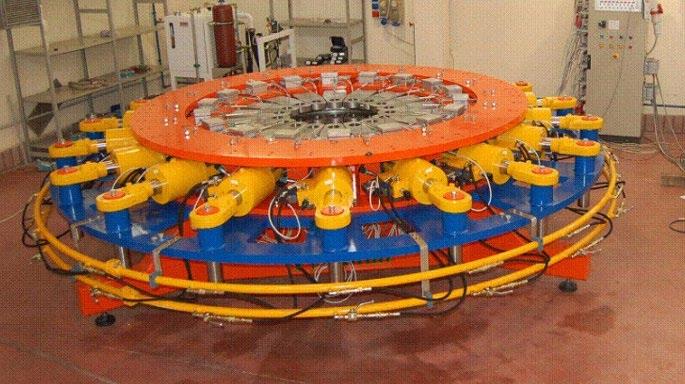
A mock-up compression ring one fifth the original size was manufactured following vacuum pressure impregnation techniques.
In January 2009 a rupture test was carried out reaching 1,400 MPa before breaking in a testing facility specifically prepared with this aim and able to provide a stress distribution in the rings similar to the one induced by the TF coils during operation (Figure 7.3.3.1).
Additional testing activities were performed during the following years on a total number of eleven sub-scale pre-compression ring mock-ups manufactured by winding S2 glass fibers on a diameter of 1m (1/5 of the full scale) both by vacuum pressure epoxy impregnation (VPI) and filament wet winding techniques (WW).
The first three rings were manufactured by ENEA Frascati with a particular VPI technique, five other mock-ups were manufactured following ENEA VPI process and three using WW technique by two different industrial companies. The rings were tested in a dedicated hydraulic testing machine consisting of 18 radial actuators working in position control with a total load capability of 1,000t. The complete testing campaign consisted of six ultimate tensile strength tests and four stress relaxation tests. The tests demonstrated that the composite (S2 glass-epoxy) was a valid and viable solution for the ITER pre-compression rings [ 55]
The next step was to place an industrial contract to manufacture, with the same technology, and test a full-size prototype that would allow advanced qualification activities that preceded the start of production (Fig.7.3.3 2). As the tests did not reach the expected positive results, it was decided to explore alternatives to manufacture these components with different technology. Eventually, the choice fell on an alternative based on pultruded composite.
Following manufacturing, stress tests were supplemented by other tests to confirm that the creep and fatigue performances were also adequate. The successful completion of the tests paved the way to the final manufacturing of the component.
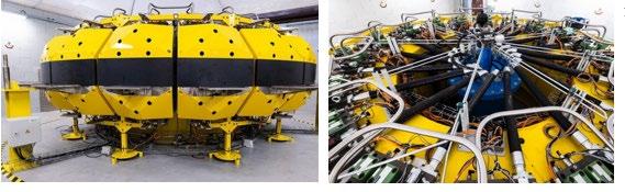
This section has been written using the following reference: M. Gasparotto et al., “Design and technical status of the EU contribution to ITER,” Fusion Engineering and Design, vol. 84, 2009[ 56]
In support of the construction of ITER, the SULTAN test facility at CRPP-Villigen was used for the characterization and qualification of the cable-in-conduit superconductors manufactured as inkind contributions by the ITER parties.
In 2007 and 2008, a number of conductor samples were tested with the aim of mitigating the observed performance degradation. The conductor qualification tests started in 2009 and was a mandatory step before launching industrial production. All samples from the ITER parties passed the qualification phase for the Toroidal Field (TF) conductor[ 57]. The qualification tests for the CS and PF conductors started in 2010.
The performance of the TF magnet conductors was qualified by a short full-size sample (4m) current sharing temperature (Tcs) test, using the operating current of 68kA and the design peak field of 11.8T. Several samples, including at least one from each of the six ITER Domestic Agencies participating in TF conductor fabrication (China, European Union, Japan, Russia, South Korea and the United States), were qualified after achieving Tcs values exceeding the ITER specification and enabled the industrial production to begin in each Domestic Agency. Some of these samples did not pass the qualification test[ 58] .
In the period between August 2010 and August 2011 the SULTAN test facility operated continuously with over one dozen test campaigns. Among the ITER conductors, five TF samples, two CS samples and four NbTi samples for PF, Correction Coil and Main Busbar coming from Japan, Russia, Korea and China were tested with in campaigns ranging from two to nine weeks each. A novel method for in-situ measurement of the critical temperature in CICC was successfully applied in SULTAN, opening the possibility to experimentally assess the thermal strain of the filaments at various stages of the test campaign, i.e. as a function of the load cycles and degradation. Residual strain measurements on the steel jacket of the TF conductors were carried out at RT and 77K.
The positive outcome of the qualification process paved the way to entering the procurement for the strand and cable production with the qualified suppliers.
As for the PF coil conductor, the positive results of the tests on the PF Conductor Insert coil completed at the CSMC facility in Naka in 2008 allowed the procurement of this component to proceed.
Using the same approach for the radial plates, the most critical component because of the large dimension and tight tolerances, several prototypes were manufactured in both the EU and JA using different processes.
This section has been written using the following references: M. Gasparotto et al., “Design and technical status of the EU contribution to ITER,” Fusion Engineering and Design, vol. 84, 2009; K. Ioki et al., “ITER nuclear components: Preparing for construction and R&D results,” Journal of Nuclear Materials, vol. 329–333, 2004[ 59] .
Thermal-hydraulic tests have been performed to confirm the vacuum vessel cooling parameters. The tests were focused on studying (1) heat transfer in differently oriented and non-uniformly heated rectangular channels, (2) flow distribution and stability in the parallel channels at the extremely low water velocities (few millimeters per second), (3) development of natural circulation in the entire vacuum vessel cooling circuit. Based on experimental results, correlations were developed describing heat transfer coefficients in the vacuum vessel channels.
The aim of the full-size, 20t Vacuum Vessel Poloidal Sector Prototype (VVPSP-Figure 7.3.3 3) built by Ansaldo Ricerche in 2004, was the manufacturing and welding together of two half-segments. The rest of the vacuum vessel was simulated by a large steel structure of similar stiffness.
The method was based on the use of massive, 80mm thick jigs welded to the inner shell of each of the four poloidal segments from the start point of the construction towards the outer shell. The jigs were required to control and reduce the distortion to achieve the final tolerance requirements. Two segments were finished separately on the jigs with the cylindrical parts welded with EB welding.
The joint between the two segments was welded. The distortions were measured by 3D Laser Scan and 85% of the surface complied with the target fabrication tolerances (± 5mm).
The manufacturing programme demonstrated the ability to successfully model and predict welding distortion. The complete assembly process was simulated with computer analysis and there was a very good agreement between actual measurements and calculations. This method was planned to be used to predict the distortion for the complete vacuum vessel sector fabrication.
A novel technique of fabricating some vacuum vessel parts using only EB welding was carried out with the support of computer calculations to predict distortions of both bending and welding operations. This was validated by a smaller mock-up, with precise, step-by-step shape distortion measurements.
In addition, a study yielded a further possible methodology of vacuum vessel manufacture which started with the completed inner shell alone and actively controls the distortion by sequential welding and also by means of jacks inside the D-space, connected to a large jig, which did not have to be welded to the shells.
QA aspects in view of fabrication were also studied
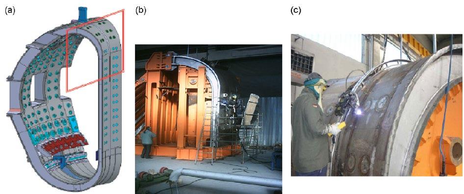
. 7.3.3.3 (a) Schematic of the size of the VVPSP, (b)
with jigs and (c) welding process.
Vacuum vessel weld inspection was also investigated as some welds had either restricted access or one-sided access only. Low angle ultrasonic testing and photo-thermal camera techniques were developed for this use.
In-Vessel Components – First Wall and Blanket Shield Modules
This section has been written using the following references: G. Federici, “European effort towards consolidating the design and manufacture of ITER in-vessel components,” Journal of Nuclear Materials, vol. 386–388, 2009[ 60]
With the ITER-FEAT design, the blanket module changed from an integrated FW on the shield block to four FW panels mechanically attached to the shield block. In addition, to simplify manufacturing and to reduce nuclear waste, this design change offered the possibility to replace the Dispersion Strengthened Copper alloy (DS-Cu) heat sink material grade with a Precipitation Hardened Copper alloy (CuCrZr). The latter class of copper alloys presents, in particular, better irradiation embrittlement properties.
However, being less stable at high temperatures, extensive R&D development work was carried out in the EU to complement the work done on DS-Cu to optimize the joining conditions for CuCrZr, specifically in joining Be to CuCrZr alloy by HIPping. The outcome was very positive and exceeded the ITER design requirements (at that time 30,000 cycles at 0.5 MW/m2 peak heat flux plus transient events up to 1.4MW/m2). Detachment of Be tiles was observed at 3MW/m2. A neutron irradiation programme was launched to complete the full characterization with irradiated mock-ups that confirmed later the good performance after irradiation [ 61] .
Brazing was also considered as an alternative, potentially cheaper, technique for joining Be tiles to the CuCrZr heat sink. A work programme was launched to develop a fast induction brazing technique to minimize the holding time at high temperature and consequently retain enough mechanical properties of the CuCrZr alloy. A few FW mock-ups were fabricated with inductively brazed Be tiles, but these showed thermal fatigue performance well below HIPped mock-ups, with detachment of Be tiles between 1.5 and 2MW/m2. This result was considered unsatisfactory and the work was stopped focusing on the development of a new silver free braze alloy.
For the manufacturing of the shield block, a design was developed based on the experience gained in the EDA L4 Large R&D Project with a shield blanket prototype fabricated by powder HIPping. This fabrication route would improve the reliability of the components e.g., by minimizing the number of seal welds exposed to vacuum and limiting the cost of machining and welding operations. The drawback of this approach was the deformation due to the shrinkage of the powder during HIPping. The larger the amount of powder, the larger the deformation. An easier approach was therefore to consider a mixed solid/powder HIP joining, using powder only where it was beneficial, e.g. for the complicated parts at the rear side of the modules.
A full-scale shield block prototype HIPped at 1,100oC and 140MPa for 4h, was manufactured and it demonstrated the feasibility of the proposed shield concept [ 62]
Material characterization was also carried out. 316L(N)-IG SS powder material and joints with oxygen content lower than 100wppm, HIPped under representative conditions, showed mechanical properties, including impact properties similar or better than those of forged 316L(N)IG SS.
A qualification programme in view of the future blanket shield procurements was launched by the ITER Organization (IO). Each Party had to demonstrate their capability to manufacture the component with the required quality. The first stage tackled the qualification of the proposed technology through a test programme using smaller mock-ups. The mock-ups were tested in two test facilities (NRI of Rez in the Czech Republic and Sandia National Laboratories in the United States). Once passed this first step, the second one would have addressed the manufacture and testing of semi-prototype FW panels.
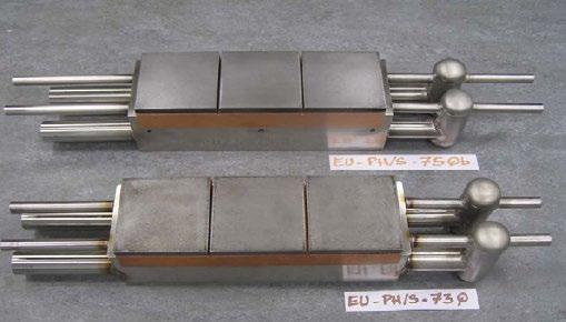
Fig. 7.3.3.4 The EU first wall qualification mock-ups
The EU FW qualification test programme also progressed. One of the two EU FW mock-ups passed the first qualification test performed at Sandia NL in the US after completion of 12,000 cycles at 0.875MW/m2 and 1,000 cycles at 1.4MW/m2 without any indication of failure. The second EU FW mock-up was also successfully tested at the NRI in the Czech Republic and achieved 12,000 cycles at 0.625MW/m2. Eventually, the 1,000 cycles at 1.75MW/m2 simulating MARFE events were successfully performed at Forschungszentrum Jülich in Germany. There, the mock-up was further tested for 100 cycles at 2.75MW/m2 fully validating HIP as a robust manufacturing technique for the considered FW materials [ 63] (Figure 7.3.3.4).
R&D continued on items closely related to the manufacturing of long lead items. For example,54 :
• Testing of cutting and rewelding of the first wall panel leg and the hydraulic connector of the shield blanket.
• Blanket FW panels to be produced also by those participants who have recently joined ITER.
This section has been written using the following reference: G. Federici, “European effort towards consolidating the design and manufacture of ITER in-vessel components,” Journal of Nuclear Materials, vol. 386–388, 2009[ 64] .
In the first decade of the years 2000, EU made a significant contribution to the development of technologies for PFCs. These technologies were validated in industries (mainly at Plansee (Austria) and Ansaldo Ricerche (Italy)) by manufacturing a large number of mock-ups and prototypes. These components were high heat flux tested in EU test facilities such as FE 200 (CEA-AREVA ANP) in France and in Judith at Juelich (Germany) at heat fluxes well above the ITER requirements[ 65] .
Carbon-Fibre-Composite (CfC) prototypes were successfully tested up to 1,000 cycles at 23 MW/m2 (at that time ITER design target was 300 cycles at 20 MW/m2) and tungsten prototypes up to 1,000 cycles at 10 MW/m2 (at that time ITER design requirement for the divertor baffle was 3 MW/m2).
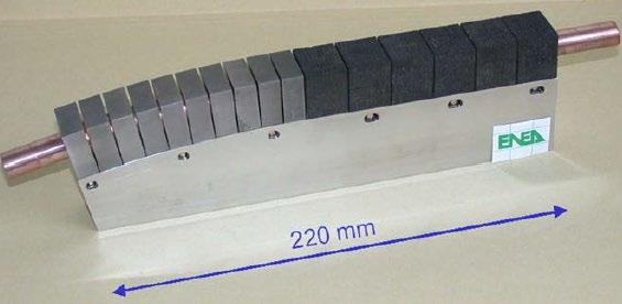
Another medium-scale vertical target prototype (see Figure 7.3.3.5) manufactured at ENEA Frascati by the ‘hot radial pressing’ technology was high heat flux tested in the FE200 electron beam facility. The mock-up sustained up to 2,000 cycles at 20MW/m2 and 15MW/m2 on CfC and W parts, respectively, without failure. An experimental critical heat flux of 35MW/m2 was determined for the CfC monoblock part.
The reproducibility of the industrial processes for the CfC armour to heat sink joining is one of the issues that were addressed by the EU R&D programme for the divertor. In fact, the presence of randomly distributed defects at armour-heat sink interface could not be excluded due to the impossibility of guaranteeing constant properties among different material batches. As a result of the manufacturing of several mock-ups and prototypes, it was clear that these defects could not be fully eliminated. Therefore, a set-up of suitable acceptance criteria was undertaken through activities carried out in collaboration with EU laboratories (e.g., CEA Cadarache and CIEMAT) and in agreement with the ITER International Team.
More than one hundred mock-ups with calibrated artificial defects were manufactured and underwent ultrasonic inspection and infrared thermography to both check the defect size and the detection capability of the two techniques. Then, the mock-ups were high heat flux tested to investigate the minimum defect size able to limit the requested performances and subjected again to ultrasonic and infrared inspections to provide evidence of defect propagation.
In the EU, two European companies were appointed to manufacture three qualification prototypes, namely one full monoblock and one mono-flat tile (Plansee); one full monoblock (Ansaldo) (Figure 7.3.3.6). The prototypes were successfully manufactured using hot hydrostatic pressing (Plansee) and hot radial pressing (Ansaldo).

The three inner vertical target qualification prototypes were completed and successfully passed the acceptance tests. High heat flux tests (the CfC part up to 20MW/m2 and the W part up to 5MW/m2 for 1,000 cycles) were performed at the Efremov Institute (RF) in September 2008.
In addition, the manufacturing of a full-scale cassette prototype and a complete set of divertor PFCs with dummy armour (inner and outer target and dome) was completed at Ansaldo Ricerche. The objectives of such activities were: (i) to verify that the cassette and PFCs could be manufactured within the specified tolerances; (ii) to validate the procedures to assemble the PFCs onto the cassette body including both the mechanical attachments and hydraulic connections; and (iii) to test the hydraulic design and to define proper procedures for draining and drying.
Heating & Current Drive
Electron Cyclotron Heating
This section has been written using the following references: M. Gasparotto et al., “Design and technical status of the EU contribution to ITER,” Fusion Engineering and Design, vol. 84, 2009[ 66] .
The diamond windows were tested at high power by the Japan Atomic Energy Agency (JAEA), using a 1MW gyrotron. The prototype steering mechanism was manufactured and tested, demonstrating frictionless, backlash-free movement.
The first prototype of a 2MW coaxial cavity gyrotron was tested at the dedicated Electron Cyclotron Test Facility (CRPP, Lausanne, Switzerland). The gyrotron operated consistently in the desired mode T34, 19 and an output power of about 1.5MW, for about 1ms, was measured. The peak power and the pulse length were limited by several issues requiring further investigation during refurbishment of the tube, which was planned for 2009.
This section has been written using the following references: B. Heinemann et al., “Negative ion test facility ELISE Status and first results,” Fusion Engineering and Design, vol. 88, 2013 67; “New world record: ELISE experimental testing facility achieves target values for ITER neutral beam heating,” Max Planck Institute for Plasma Physics, 2024[ 68]; V. Toigo, “Progress in the ITER neutral beam test facility,” Nuclear Fusion, vol. 59, 2019[ 69]
R&D programmes in Japan and Europe were instrumental in helping to close the gap between current technology and what was needed for the ITER neutral beam programme.
The negative source ELISE (Extraction from a Large Ion Source Experiment) has been in operation at the Max-Planck Institute for Plasma Physics since 2009. The source is half the size of what is projected for ITER and has been a valuable source of experimental data as technological solutions are still being tested here.
In 2015 the ion source achieved operation pulses lasting one hour, during which a stable and homogeneous ion beam of nine amperes lasting 20 seconds could be produced every three minutes. The gas pressure in the source and the quantity of the electrons retained conformed to ITER specifications. In March 2024, scientists achieved in ELISE a negative hydrogen ion current density of almost 300 A/m2 for 600 seconds. This enabled them to increase the previously possible pulse length for such current densities by more than tenfold. For shorter pulses lasting ten seconds, 330A/m2 were generated.
However, it was deemed necessary to have a facility that could achieve the requirements for the ITER neutral beam system in terms of power, energy, and pulse length simultaneously.
In 2007, following an important design review carried out to assess the situation of the project, the technical supervisory bodies (i.e. ITER Council, ITER Technical Advisory Committee, Management Advisory Committee) strongly supported a major R&D programme to develop a system to obtain a negative ion beam with high energy (1MeV) and power (16.5MW), and with an almost continuous operation capacity, which would serve to heat the ITER plasma.
Following the final approval by the ITER Council, in 2012 construction started in Padua (Italy) for PRIMA (Padova Research on ITER Megavolt Accelerator), including a full-size negative ion source, SPIDER, and a full-size prototype of the whole ITER injector, MITICA, with an ion source identical to SPIDER, capable of operating at full power and voltage. This facility was made with the main contribution of the EU (through the Joint Undertaking for ITER (F4E)) and additional support by the ITER Organization and Consorzio RFX which hosts the Test Facility. The Japanese and the Indian ITER Domestic Agencies participated in the PRIMA enterprise with technical and scientific support granted by various laboratories and universities.
SPIDER is one of two projects of the ITER Neutral Beam Test Facility (NBTF), has a 100keV beam source with a full-size prototype of the radiofrequency ion source for the ITER neutral beam injector and also, similar to the ITER diagnostic neutral beam, it is designed to operate with a pulse length of up to 3,600s.
Construction and installation of SPIDER plant systems was successfully completed with their integration into the facility. Integrated commissioning with the control, protection and safety
systems ended positively and the SPIDER operation began in June 2018 with its first experimental phase in 2019.
MITICA, the prototype of the 1MV injector, is in an advanced stage of construction.
Divertor Test Platform 2 (DTP-2) was commissioned in Tampere (Finland) in 2007 and provided the basis of extensive investigations on remote maintenance (Figure 7.3.3.7).
Remote handling equipment and operations were developed and tested. Operations with Cassette Multifunctional Mover (CMM) were performed fully remotely from the control room using virtual models. Water hydraulic manipulator (WHMAN) to provide assistance to CMM during Second Cassette installation and removal operations was further developed and tested. A new cassette inner attachment was manufactured and its behaviour during locking and unlocking was tested on DTP2. A new version of the cassette outer locking system was later developed, manufactured and tested in 2011.
DTP2 trials in 2011 included successful CMM/SCEE (second cassette end-effector) recoverability tests and second cassette replacement trials subject to cassette misalignments. Control systems of CMM and WHMAN were updated. Design and procurement activities focused on improvement of the second cassette end-effector as well as on design of the diagnostic rack end-effector and the CTM tunnel umbilical. The Remote Handling Control System was used in DTP2 control room (Figure 7.3.3.8) for handling the prototypes of ITER divertor maintenance system. In 2011 the system was entering the demonstration phase.
In 2013 RH-trials on the exchange of the central and the second divertor cassette were repeated, since the divertor cassette and its locking system were modified substantially after the first tests.
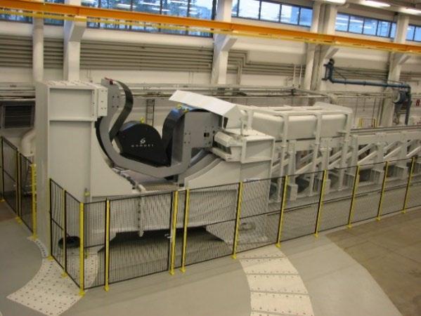
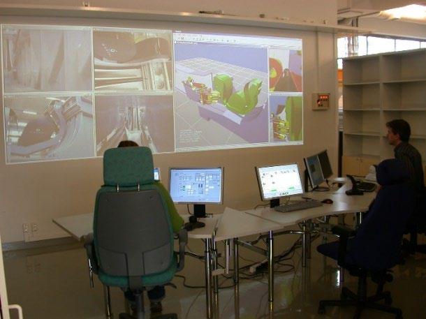
The DTP2 has also been used to test technologies developed for the final RH system in ITER. More specifically:
• water-hydraulic digital valves to replace the servo valves on board the Cassette Multifunctional Mover;
• augmented reality with the use of marker to identify the position of the cassette locking system.
• remote diagnostic application (for early detection of anomalies in the behaviour of the RH devices/tools to prevent failure during operation);
• use of specifically developed middleware for RH control system standardization for the final system in ITER.
Abbreviations & Glossary
AC Alternating Current
AGHS Active Gas Handling System
BTP Blanket Test Platform
CDA Conceptual Design Activities
CEA Commissariat à l'énergie atomique
CfC Carbon fibre Composite
CICC Cable in Conduit Conductor
CIEMAT Centro de Investigaciones Energéticas, Medioambientales y Tecnológicas
CMM Cassette Multifunctional Mover
CRPP Centre de Recherches en Physique des Plasmas
CS Central Solenoid
CSMC Central Solenoid Model Coil
CW Continuous Wave
D Deuterium
DOE Department of Energy
DS Dispersion-strengthened
DTP Divertor Test Platform
EB Electron Beam
EC Electron Cyclotron
EDA Engineering Design Activities
ELISE Extraction from a Large Ion Source Experiment
EMF Electric and Magnetic Forces
EU European Union
F4E Fusion for Energy
FEAT Fusion Energy Advanced Tokamak
FW First Wall
FZK Forschungszentrum Karlsruhe
H&CD Heating and Current Drive
HHFC High heat flux component
HIP Hot Isostatic Pressing
HT Home Team
IAEA International Atomic Energy Agency
IC Ion Cyclotron
IEA International Energy Agency
IO ITER Organization
IUA ITER Unit of Account
JAERI Japan Atomic Energy Research Institute
JCT Joint Central Team
JRC Joint Research Centre
LCT Large Coil Task
LH Lower Hybrid
LOVA Loss of Vacuum Accident
MAG Metal Active Gas
MITICA Megavolt ITER injector and concept Advancement
NB Neutral Beam
NBTF Neutral Beam Test Facility
OF Oxygen-free
PF Poloidal Field
PFC Plasma Facing Component
PFCI Poloidal Field Conductor Insert
PFD Process Flow Diagram
PRIMA Padova Research on ITER Megavolt Accelerator
PSP Poloidal Sector Prototype
QA Quality Assurance
R&D Research and Development
RD&D Research, Development, and Demonstration
RF Russian Federation
RIEMF Radiation-induced electric and magnetic forces
RH Remote Handling
SB Shield Blanket
SCEE Second Cassette End-Effector
SiC Silicon carbide
SPIDER Source for the Production of Ions of Deuterium Extracted from an RF plasma
T Tritium
TCPSA Thermally Coupled Pressure Swing Adsorption
TF Toroidal Field
TFCI Toroidal Field Conductor Insert
TFMC Toroidal Field Model Coil
TLK Tritium Laboratory Karlsruhe
TPL Tritium Processing Laboratory
TSTA Tritium Systems Test Assembly
US United States
UT Ultrasound Testing
VDE Vertical Displacement Event
VPI Vacuum Pressure Impregnation
VV Vacuum Vessel
WHMAN Water hydraulic manipulator
WW Wet Winding
References
[1] ITER Conceptual Design Report, ITER Documentation Series No. 19, IAEA 1991.
[2] ITER Conceptual Design Report, ITER Documentation Series No. 18, IAEA 1991.
[3] ITER Concept Definition Vol. 2, ITER Documentation Series No. 3, IAEA 1989.
[4] ITER Containment Structures, ITER Documentation Series No. 28, IAEA 1991.
[5] ITER Assembly and Maintenance, ITER Documentation Series No. 34, IAEA 1991.
[6] D. Maisonnier et al., Remote handling of the blanket segments: testing of 1/3 scale mock-ups at the “Robertino” facility, Fusion Engineering and Design Vol. 29, March 1995.
[7] A. T. Ramsey et al., “DT radiation effects on TFTR diagnostics,” Review of Scientific Instruments, vol. 66, no. 1, pp. 871–876, 1995.
[8] C. H. Skinner et al., “Studies of tritiated co-deposited layers in TFTR,” Journal of Nuclear Materials, vol.
ITER DESIGN EVOLUTION AND DESIGN MATURATION
Vol.1, Ch. 7/3, p. 56
290–293, pp. 490–496, 2001.
[9] J. D. Strachan et al., “Neutron calibration techniques for comparison of tokamak results,” Review of Scientific Instruments, vol. 61, no. 12, pp. 3501–3504, 1990.
[10] G. Vayakis et al., “Generic issues for a burning plasma experiment,” Fusion Science and Technology, vol. 53, no. 3, pp. 699–750, 2008.
[11] E. R. Hodgson, “General radiation problems for insulating materials for future fusion devices,” Journal of Nuclear Materials, vol. 258–263, pp. 226–233, 1998.
[12] V. Voitsenya et al., “Diagnostic first mirrors for burning plasma experiments,” Review of Scientific Instruments, vol. 71, no. 1, pp. 475–480, 2001.
[13] T. Mizoguchi, “ITER technology R&D during the EDA,” Jul. 2001.
[14] ITER Technical Basis, ITER EDA Documentation Series, no. 24, International Atomic Energy Agency, Vienna, Austria, 2002.
[15] Y. Shimomura, ITER Technology R&D, Fusion Engineering and Design Vol. 55, July 2001.
[16] N. Martovetsky et al., Test of the ITER TF Insert and Central Solenoid Model Coil, IEEE Transactions on Applied Superconductivity, Vol. 13, No. 2, June 2003.
[17] D. Bessette et al., Test Results from the PF Conductor Insert Coil and Implications for the ITER PF System, IEEE Transactions on Applied Superconductivity, Vol. 19, No. 3, July 2009.
[18] K. Ioki et al., “Convergence of design and fabrication methods for ITER vacuum vessel and in-vessel components,” in Proc. IAEA Fusion Energy Conference 2004, Vilamoura, Portugal, 2004
[19] K. Ioki et al., “ITER-FEAT vacuum vessel and blanket design features and implications for the R&D programme,” Nuclear Fusion, vol. 41, no. 3, pp. 309–321, Mar. 2001, doi: 10.1088/0029-5515/41/3/305
[20] K. Koizumi et al., “Fabrication and assembly of full-scale sector models for ITER vacuum vessel,” in Proc. 13th Topical Meeting on the Technology of Fusion Energy, 1998.
[21] W. Daenner et al., “Progress of and future plans for the L-4 blanket project,” in Proc. IAEA Fusion Energy Conference 2000, paper IAEA-CN-77/ITERP/18, 2001.
[22] N. Mitchell et al., “Design of the ITER magnets to provide plasma operational flexibility,” in Proc. IAEA Fusion Energy Conference 2004, Vilamoura, Portugal, 2004.
[23] F. Elio et al., “Design and development of the ITER blanket backplate flexible supports,” in Proc. 20th Symposium on Fusion Technology, Marseille, France, 1998.
[24] C. Day et al., “Validated design of the ITER main vacuum pumping systems,” in Proc. IAEA Fusion Energy Conference 2004, Vilamoura, Portugal, 2004.
[25]S. Gross, “Tritium activities in Germany,” Fusion Science and Technology, vol. 41, no. 3, pp. 325–332,
2002, doi: 10.13182/FST02-A22605.
[26] S. Tanaka, M. Nishikawa, Y. Ichimasa, and M. Nishi, “Activities of tritium studies in Japan,” Fusion Science and Technology, vol. 41, no. 3, pp. 305–312, 2002, doi: 10.13182/FST02-A22602.
[27] R. S. Willms and R. Rabun, “US tritium activities,” Fusion Science and Technology, vol. 41, no. 3, pp. 339–346, 2002, doi: 10.13182/FST02-A22608.
[28] A. A. Yukhimchuk, “Tritium activities in Russia,” Fusion Science and Technology, vol. 41, no. 3, pp. 334–338, 2002, doi: 10.13182/FST02-A22607.
[29] J. M. Miller, “Overview of Canadian activities in tritium,” Fusion Science and Technology, vol. 41, no. 3, pp. 314–324, 2002, doi: 10.13182/FST02-A22603.
[30] B. M. Andreev, E. P. Magomedbekov, and G. H. Sicking, Interaction of hydrogen isotopes with transition metals and intermetallic compounds, Springer Tracts in Modern Physics, vol. 132, Springer, 2006.
[31] J. R. Bartlit, “The tritium systems test assembly at Los Alamos National Laboratory,” Fusion Engineering and Design, vol. 12, no. 3, pp. 393–400, 1990, doi: 10.1016/0920-3796(90)90012-U.
[32] R. S. Willms, K. Kobayashi, Y. Iwai, T. Hayashi, S. O’hira, M. Nishi, D. Hyatt, and R. V. Carlson, “Behavior of tritium in the TSTA test cell combined with operation of the experimental tritium cleanup (ETC) system,” Fusion Engineering and Design, vol. 61–62, pp. 575–582, 2002, doi: 10.1016/S0920-3796(02)00292-2.
[33] R. H. Sherman, D. J. Taylor, T. Yamanishi, M. Enoeda, S. Konishi, and K. Okuno, “The role of sidestream recycle in hydrogen isotope separation and column cascade design,” Fusion Engineering and Design, vol. 28, pp. 392–398, 1995, doi: 10.1016/0920-3796(95)90066-7.
[34] L. Dörr, U. Besserer, M. Glugla, G. Hellriegel, W. Hellriegel, P. Schäfer, and J. Wendel, “The closed tritium cycle of the Tritium Laboratory Karlsruhe,” Fusion Science and Technology, vol. 48, no. 1, pp. 262–269, 2005, doi: 10.13182/FST05-A924.
[35] M. Glugla and R. D. Penzhorn, “Development of fusion fuel cycle technology at the Tritium Laboratory Karlsruhe: The experiment CAPRICE,” Fusion Engineering and Design, vol. 28, pp. 348–354, 1995, doi: 10.1016/0920-3796(95)90059-4.
[36] B. Bornschein et al., “Successful experimental verification of the tokamak exhaust processing concept of ITER with the CAPER facility,” Fusion Science and Technology, vol. 48, no. 1, pp. 11–17, 2005, doi: 10.13182/FST05-A870.
[37] D. Demange et al., “CAPER as central and crucial facility to support R&D with tritium at TLK,” Fusion Science and Technology, vol. 67, no. 2, pp. 308–314, 2015, doi: 10.13182/FST14-T17.
[38] L. Dörr et al., “High resolution vacuum calorimeter,” Fusion Science and Technology, vol. 48, no. 1, pp. 358–364, 2005, doi: 10.13182/FST05-A942).
[39] T T. Hayashi et al., “Safe handling experience of a tritium storage bed,” Fusion Engineering and Design, vol. 83, no. 3–4, pp. 429–433, 2008, doi: 10.1016/j.fusengdes.2008.07.010.
[40] S. O’hira et al., “Design study of a tritium transport package for future fusion reactors,” Fusion
Engineering and Design, vol. 45, no. 2, pp. 187–194, 1999, doi: 10.1016/S0920-3796(99)00016-2.
[41] M. Yamada et al., “Operation experience on safety system of tritium process laboratory in Japan Atomic Energy Research Institute,” Fusion Technology, vol. 28, no. 3, pp. 1376–1381, 1995, doi: 10.13182/FST95-A30604.
[42] S. O’hira, T. Hayashi, and K. Okuno, “Tritium safety-related studies at TPL of JAERI,” Journal of Fusion Energy, vol. 16, no. 3, pp. 219–226, 1997.
[43] T. Kinjyo et al., “Chemical form of released tritium from solid breeder materials under various purge gas conditions,” Fusion Engineering and Design, vol. 82, no. 15–24, pp. 2147–2153, 2007, doi: 10.1016/j.fusengdes.2007.07.002.
[44] S. Konishi, M. Hara, and K. Okuno, “Plasma exhaust processing by palladium permeation and electrolytic oxidation and reduction,” Fusion Technology, vol. 30, no. 3, pp. 890–895, 1996, doi: 10.13182/FST96-A11963050.
[45] S. O’hira et al., “Beta induced reaction study on T₂–CO system,” Fusion Engineering and Design, vol. 49–50, pp. 905–910, 2000, doi: 10.1016/S0920-3796(00)00334-3.
[46] L. Horton et al., “JET experiments with tritium and deuterium–tritium mixtures,” Fusion Engineering and Design, vol. 109–111, pp. 925–930, 2016, doi: 10.1016/j.fusengdes.2016.01.051.
[47] C. A. Gentile et al., “The operation of the TFTR tritium system,” in Proc. IEEE Symposium on Fusion Engineering 1997, San Diego, CA, USA, 1997, pp. 283–285, doi: 10.1109/FUSION.1997.687038.
[48]C. Skinner et al., “Plasma wall interaction and tritium retention in TFTR,” Journal of Nuclear Materials, vol. 241–243, pp. 214–220, 1997, doi: 10.1016/S0022-3115(97)80041-4.
[49]P. Andrew et al., “Tritium retention and clean-up in JET,” Fusion Engineering and Design, vol. 47, pp. 233–240, 1999, doi: 10.1016/S0920-3796(99)00084-8.
[50] D. Mazon et al., “Introduction to diagnostic measurement in ITER,” Nuclear Fusion, to be published.
[51] A. J. H. Donné et al., “Chapter 7: Diagnostics,” Nuclear Fusion, vol. 47, pp. S337–S384, 2007.
[52] R. Vila and E. R. Hodgson, “RIEMF in MgO and Al₂O₃ MI cable ITER magnetic diagnostic coils,” Journal of Nuclear Materials, vol. 329–333, pp. 1524–1528, 2004.
[53]M. Rubel et al., “Mirror test for ITER at the JET tokamak: An overview,” Review of Scientific Instruments, vol. 77, 063501, 2006.
[54] Y. Shimomura, “ITER towards construction,” in Proc. IAEA Fusion Energy Conference 2004, 2004.
[55] P. Rossi et al., “Overview of the testing activities on ITER sub-scale pre-compression rings,” Fusion Engineering and Design, vol. 87, Aug. 2012.
[56] M. Gasparotto et al., “Design and technical status of the EU contribution to ITER,” Fusion Engineering and Design, vol. 84, 2009.
[57] P. Bruzzone et al., “Test of ITER conductors in SULTAN: An update,” Fusion Engineering and Design, vol. 86, 2011.
[58] M. Breschi et al., “Results of the TF conductor performance qualification samples for the ITER project,” Superconductor Science and Technology, vol. 25, 2012.
[59] K. Ioki et al., “ITER nuclear components: Preparing for construction and R&D results,” Journal of Nuclear Materials, vol. 329–333, 2004.
[60] G. Federici, “European effort towards consolidating the design and manufacture of ITER in-vessel components,” Journal of Nuclear Materials, vol. 386–388, 2009.
[61] P. Lorenzetto, “EU contribution to the procurement of the ITER blanket first wall,” Fusion Engineering and Design, vol. 109–111, pp. 661–665, 2016.
[62] C. Boudot, “Manufacture of a shield prototype for primary wall modules,” Fusion Engineering and Design, vol. 83, pp. 1294–1299, 2008.
[63] F. Zacchia, “Fabrication and testing of the EU FW qualification mock-ups,” in Proc. IAEA Fusion Energy Conference 2010, Daejeon, Korea, 2010.
[64] G. Federici, “European effort towards consolidating the design and manufacture of ITER in-vessel components,” Journal of Nuclear Materials, vol. 386–388, 2009.
[65] Y. Shimomura, ITER Technology R&D, Fusion Engineering and Design Vol. 55, July 2001.
[66] M. Gasparotto et al., “Design and technical status of the EU contribution to ITER,” Fusion Engineering and Design, vol. 84, 2009.
[67] B. Heinemann et al., “Negative ion test facility ELISE Status and first results,” Fusion Engineering and Design, vol. 88, 2013.
[68] “New world record: ELISE experimental testing facility achieves target values for ITER neutral beam heating,” Max Planck Institute for Plasma Physics, 2024.
[69] V. Toigo, “Progress in the ITER neutral beam test facility,” Nuclear Fusion, vol. 59, 2019.