







This handbook consists of two volumes which describe the ITER design from its inception up to the design, construction and assembly in 2025
The handbook is not designed to be read as a continuous sequence of chapters. Instead, it is composed of focused, self-contained sections that address specific topics. Each chapter can be read and understood independently, allowing readers to engage with the material most relevant to their needs without requiring familiarity with preceding chapters. As a result, the reader will find certain overlapping content in chapters.
It is to be noted that at the time of writing, the design for some systems is still on-going. Therefore, the reader should consider that whilst there is significant value of this important point-in-time study, an update would be required as the Project progresses
A broad Project overview is given in the first volume, to provide the reader with background information necessary to understand the context in the subsequent more-detailed chapters of the second volume, dedicated to the individual systems composing ITER.
For the overall table of contents of the Handbook and to access each one of the chapters, please refer to htps://www.iter.org/scien�sts/iter-technical-reports/iter-engineering-basishandbook.
This chapter is authored by Gianfranco Federici and co-authored by the Handbook Editors Federico Casci, Stefano Chiocchio, Richard Hawryluk, John How, Akko Maas, Masanori Onozuka, René Raffray, Gabriella Saibene, Bill Spears and Eisuke Tada
4.6.5
4.6.6
Since the early eigh�es the fusion scien�fic community has focused its Research and Development ac�vi�es on providing the base of data to ensure the successful design, construc�on and opera�on of an experimental fusion reactor to achieve reactor-relevant burning plasma condi�ons, which is recognised to be the primary challenge faced by fusion research today and the necessary step towards the demonstra�on of fusion as a source of energy. During this period the knowledge on reactor relevant plasma physics performance improved drama�cally thanks mainly to advances achieved with experiments, modelling and technology developments. These advances have led to the design of ITER, conceived to be the first large tokamak to produce plasmas with the alpha-hea�ng domina�ng over the external hea�ng power.
ITER's mission - to establish the scien�fic and technological basis for the peaceful exploita�on of fusion energy and to demonstrate the safety and environmental poten�al of fusion energy produc�on and thereby provide a precedent for the safe opera�on of future fusion power plants - provides a fundamental principle for the design and construc�on of all elements of the ITER tokamak facility. It undoubtedly represents the cri�cal step from today’s magne�c confinement fusion (MCF) experiments to future fusion energy demonstra�on power plants.
The performance and opera�ng requirements of ITER in terms of power, pulse lengths, duty cycles, and availabili�es represent a very large extrapola�on from current experience and place a
huge constraint on design integra�on, fabrica�on, assembly, component reliability, and maintenance procedures. However, the data derived from ITER on these issues are essen�al to realising prac�cal fusion power plants.
From the beginning, these ambi�ous objec�ves affected the design and construc�on of the ITER tokamak facility. Although there is a strong physics and technology basis, there are s�ll uncertain�es and important issues for burning-plasma research, giving rise to significant risks and requiring robust design and technology solu�ons.
The main physics and engineering challenges impac�ng the design and fabrica�on of the ITER systems include:
a) the unprecedented size and performance requirements for some of the core systems, i.e. the ITER superconduc�ng magnet systems, the vacuum vessel etc;
b) the huge electromagne�c forces on the mechanical structures of the tokamak;
c) the high-power fluxes for long dura�ons to the divertor targets and to the first wall. These must be ac�vely cooled to remove the plasma heat fluxes as well as the neutron hea�ng, the later also deposited deep in the shielding blanket and the vacuum vessel surrounding the plasma. Further challenges arise from the addi�onal demands imposed by very high transient heat pulses on the plasma facing components (PFCs) generated by plasma instabili�es;
d) the high neutron flux and the radia�on shielding requirements complicated by the constraints of a complex tokamak geometry that challenges the disposi�on of fully effec�ve shielding (neutron streaming across penetra�ons on the outboard also represents a serious design issue while a biological shield is necessary to keep the radia�on biological dose outside the reactor within the maximum permissible dose for occupa�onally exposed individuals;
e) the development and deployment of efficient and reliable plasma hea�ng and current drive, fuelling, diagnos�c and instability control/mi�ga�on systems capable of rou�ne opera�on in the burning plasma environment;
f) the need to handle and reprocess tri�um at an unprecedented scale to sa�sfy the fuel requirements of the burning plasma programme, to limit in-vessel fuel reten�on and to assure the required degree of tri�um containment;
g) the provision of remote maintenance tools and facili�es to allow repair, maintenance and upgrades in an ac�vated environment;
h) the millimetric and in some cases sub-millimetric alignment and/or very demanding fabrica�on tolerances on components of complex shape and large dimensions;
i) the need to develop fully qualified fabrica�on methods and to overcome the limited industrial manufacturing experience in some of the u�lised technologies. This o�en occurs for first-of-a-kind (FOAK) supplies in some areas, and there is the need to address uncertain�es with extensive tes�ng and qualifica�on;
j) the integra�on of prototypical tri�um breeding blanket modules and their associated subsystems into the tokamak environment for the first �me; k) the need to comply with �ght nuclear regula�ons in terms of safety set by the French regulators.
These challenges explain the thoroughness and the length of the design ac�vi�es and of the suppor�ng R&D which has been carried out. Designing and construc�ng the tokamak, auxiliary and plant systems which make up the ITER facility have necessitated extensive R&D programmes characterised by wide-ranging, long-term interna�onal collabora�ons and major innova�ons. The pooling of resources from all the major fusion programmes in the world alleviated the difficul�es that a single programme would have in construc�ng such a large-scale fusion experiment. The cross fer�lisa�on of ideas and exper�se proved to be very beneficial in technical terms, and this, together with the shared risk and pooled resources, more than offset the greater complexity in organisa�on and management and the many interface problems to be solved.
However, ITER remains an experimental facility with opera�onal risks arising from the uncertain�es of the plasma physics and many FOAK components and systems, implying that there are s�ll significant risks and uncertain�es in the design, fabrica�on and assembly of the core components and their opera�on as single items and as part of the whole reactor, to ensure that the device can reach the required performance in terms of parameters such as the fusion power, fusion gain and pulse length. A built-in flexibility to accommodate these uncertain�es, allowing adapta�on in response to issues which emerge during opera�on, is essen�al, albeit not easy to implement.
The scien�fic and technological challenges associated with ITER’s performance objec�ves and requirements are formidable, and this chapter atempts to highlight the main engineering challenges together with its major technical differences with exis�ng devices. Specific manufacturing and assembly challenges are men�oned in Chapter 8 and extensively described in Vol. 2. Sec�on 2 in this chapter concisely describes the main features of a burning plasma. Sec�on 3 summarises the ra�onale behind the choice of the main objec�ves and the technical parameters of ITER and its evolu�on during the �me. Sec�on 4 provides a brief descrip�on of the ITER design. Sec�on 5 addresses some of the most dis�nc�ve features of ITER and the main differences with exis�ng devices. Finally, Sec�on 6 describes the features of essen�al ITER enabling technologies and the associated challenges encountered in their design and realisa�on. A more exhaus�ve descrip�on of all the systems that composed the ITER facili�es can be found in the second volume of this handbook.
ITER is a FOAK fusion facility based on its scale, technical specifica�ons, and integra�on of systems, but is also a FOAK for licensing. As a mater of fact, regulatory challenges exist as the fusion process in the ITER machine involves specific nuclear hazards due to its radioac�ve inventory, namely tri�um, ac�vated products and wastes such as tri�ated and ac�vated wastes. In France, this means that the ITER machine is a nuclear facility which is classified as a Basic Nuclear
Installa�on (Installa�on Nucléaire de Base, INB) by French Regula�ons. Nuclear safety is a top priority issue for the ITER project, its staff and workers on site, and local popula�on and the environment.
Due to nuclear safety characteris�c of the machine and according to ar�cle 14 of the ITER Agreement, the IO has been asked to get a licence from the French Nuclear Safety Authority that has nuclear safety regula�ons that the IO must comply with for construc�on, opera�on and decommissioning of the ITER machine. The so called INB Order of February 2012 that forms the basis for licensing and authorisa�on for construc�on and opera�on of nuclear facili�es in the French territory is of special relevance. The licencing process of ITER is described in Chapter 8 and the Quality Assurance (QA) and Quality Control (QC) Programme are also described in Chapter 8. The contribu�on of ITER to fusion science and engineering is immense. The next genera�on of fusion devices will be able to learn from ITER’s return of experience across topics including the details of the design, manufacture, assembly and opera�on that could not have been learned otherwise.
In a burning plasma, ions undergo thermonuclear fusion reac�ons, which supply self-hea�ng to the plasma [ 1]. The plasma requirements for achieving sufficient thermonuclear reac�ons in a fusion device are lowest using the hydrogen isotopes of deuterium and tri�um, due to the high reac�on rate at the same temperature (see Fig. 4.1). in fact, the total energy released per DT fusion event is 17.6 MeV, of which 20% is carried by the resultant alpha par�cle and 80% by a neutron.
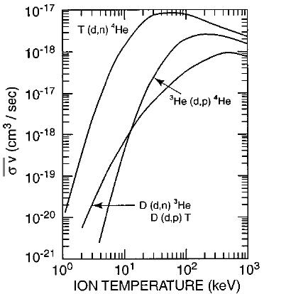
Fig. 4.1 Rate coefficients for fusion reactions of importance in magnetic fusion, plotted vs ion temperature [1].
A burning plasma is a plasma that is dominantly self-heated by fusion products from thermonuclear reac�ons in the plasma (i.e. alpha par�cles for DT fusion). This defini�on can be made more quan�ta�ve by considering the fusion energy gain Q defined as the ra�o of the fusion power Pfusion to the externally supplied hea�ng power Pheat:
Q = Pfusion/Pheat = 5Pα/Pheat
The factor of 5 applies for DT fusion, since the power carried by alpha par�cles, Pα, is 1/5 of the fusion power. The alpha par�cle hea�ng frac�on is defined as fα = Pα/(Pα + Pheat), which can also then be expressed as fα = Q/(Q + 5). “Breakeven” is defined as Q = 1, which corresponds to an alpha hea�ng frac�on of fα = 17%.
The “burning plasma” regime corresponds to Q ≥ 5, for which self-hea�ng by alpha par�cles supplies at least half of the plasma hea�ng (i.e. fα ≥ 50%). ITER is designed to achieve Q = 10 (or fα = 66%). When the alpha par�cles supply all the hea�ng (fα = 100%), external hea�ng is unnecessary, and Q becomes infinite; this is defined as the “igni�on” regime.
A review of the scien�fic issues for burning plasmas in ITER may be found in the documents ITER Physics Basis [ 2], Progress in the ITER Physics Basis [ 3] and the Interna�onal Tokamak Physics Ac�vity (ITPA) 2025 special issue on burning plasmas [ 4]. The ITER device will address key scien�fic issues in confinement, magnetohydrodynamic (MHD) stability, divertor physics, plasma–wall interac�ons, alpha-par�cle physics, and non-induc�ve steady-state opera�on at the reactor scale. It should, therefore, provide the addi�onal understanding in physics and the key valida�on of technology required to allow the magne�c fusion program to proceed to the design of a
THE ROLE AND DISTINCTIVE FEATURES OF
Vol.1, Ch. 4, p. 6
demonstra�on tokamak power plant. The scien�fic issues relevant for ITER are described in the second volume in Chapter 4 [ 5].
For MCF, which is the focus here, essen�ally, two paths have been followed in the approach to burning plasmas physics. One is the high-temperature path, which has been used by TFTR [ 6], JET [ 7], and other facili�es like JT-60U [ 8] and which will also be used by ITER. The other is the highdensity path, for which compact high magne�c-field tokamaks have been proposed and will be very briefly discussed in Sec�on 3.
Important experiments using ITER-relevant fuel mixtures were conducted in the Tokamak Fusion Test Reactor (TFTR) in the US (1993–1997) [5] and in the Joint European Torus (JET) in Europe, first in 1991, then in the Deuterium Tri�um Experiment 1 (DTE1) in 1997 [6] and more recently (DTE2) in 2021 [ 9] and (DTE3) 2023. In summary, by exploi�ng the unique capabili�es of these devices, a few important physics and engineering issues of relevance for ITER design and opera�on were explored. These include:
a) demonstra�on of high fusion power, sustained for a few seconds (this dura�on was limited by the thermal iner�a of uncooled tokamak’s wall and divertor and copper magne�c coils);
b) demonstra�on of significant α-par�cle hea�ng effects;
c) addressing of key plasma-wall interac�on issues; the use of carbon as plasma facing material led to unacceptably high T fuel reten�on both at TFTR and JET, and in the later, it was decided to refurbish the device (2009–2011) with a material mix that was considered to be more atrac�ve for ITER, consis�ng of a combina�on of Be �les in the main chamber and W in the divertor);
d) demonstra�on at JET of radio-frequency hea�ng schemes relevant to ITER DT opera�on;
e) neutronics measurements and valida�on of neutron streaming modelling and of predic�ons of the ITER shutdown dose rates [ 10]. For reference, the neutron flux levels measured at the JET first wall were of the same order of magnitude of those expected at the rear ITER blanket/diagnos�c first wall for ITER Q = 10 opera�on and the in-vessel ����radia�on field in JET due to neutron ac�va�on a�er DTE2 was as intense as that expected in some maintenance loca�ons of ITER
In conclusion, in terms of fusion performance, TFTR opera�ng with 50/50 DT plasmas achieved PDT = 10.7 MW and Q = 0.27, and JET achieved PDT of 16 MW and Q = 0.6 in 1996, and a fusion energy record output of 59 MJ in a five-second pulse in December 2021. Despite these records, neither TFTR nor JET have reached breakeven condi�ons, primarily due to their small plasma size (see Sec�on 3). ITER will have a plasma volume 10 �mes that of JET.
The size of ITER or any burning-plasma experiments is determined by several factors. One is the requirement to achieve sufficient confinement to reach the burning state, which is determined by scaling predic�ons for the energy confinement �me or the fusion triple product (density x temperature x confinement �me). This is determined from size-scaling rela�onships [ 11], [12] derived from experiments on tokamaks with plasma volumes spanning two orders of magnitude; the largest of these tokamaks already operate at plasma densi�es and temperatures like those expected in ITER though at reduced confinement �mes, given their smaller size. Another factor is the requirement that the power handling of the plasma-facing components, especially the divertor, must be able to handle the heat loads under burning plasma condi�ons. A third factor is the need to provide adequate radia�on shielding of the cri�cal equipment, i.e., the superconduc�ng magnets.
Clarifica�on, on the basis on simple intui�ve considera�ons, is first needed as to why ITER must be larger than current devices to reach its mission objec�ve.
1) First, it must achieve sufficient plasma confinement.
The so-called triple product, n T τe (where n is the plasma density, T is the plasma temperature and τe is the plasma confinement �me) required to sustain a fusion plasma with a Q=10 in ITER for long pulses (of the order of several minutes) must be typically: n T τe > 3x10²¹ keV s m-3 (1)
The op�mal plasma temperature is typically around 10 to 29 keV. The density is not a free parameter as one needs a magne�c field to confine the plasma and the magne�c pressure scales with the square of the magne�c field (B2). The ra�o between the plasma kine�c pressure, p (the product nT) and the magne�c pressure is called beta (β) and its achievable value is unfortunately rela�vely low (few %) to avoid or minimise plasma MHD instabili�es.
β ~ nT/ B2 (1a)
Therefore, the plasma pressure scales with B2 and for a typical value of the density of 1020 m-3 , τe in ITER must be around 3s to sa�sfy equa�on 1.
The energy confinement �me τe depends on many factors and is determined from empirical scaling laws derived from experiments in tokamaks. For a machine-like ITER, it can be shown that, according to one of the most common empirical scaling (IPB98):
�������� ~ ����2 6 ����1 55 (1b)
Thus combining (1a) and (1b) ones derives that nT�������� ~ ����2 6 ����3 55 (1c)
to reach a value of 3x10²¹ keV s m-3 (from equa�on (1) the machine radius must be of the order of 6.2 m. These qualita�ve arguments are developed in more detailed calcula�ons which consider other physics effects including density limits and more recent empirical scaling laws and should not be used for design purposes. This is discussed further in Volume 2, Chapter 4.
2) A second important design considera�on is that the plasma-facing components, especially the divertor, must be able to handle the heat loads under burning plasma condi�ons.
One of the crucial points in the dimensioning of ITER and any power producing fusion plant, remains the amount of power that can be reliably produced and controlled within it. This heavily depends, amongst other things, on the heat load that can be tolerated by the divertor under normal and off-normal opera�on [ 13].
In fission power plants the heat produced by the fission nuclear reac�ons in the fuel rods is absorbed and transported by the coolant (typically water) where they are immersed. In fusion devices instead, the heat by the fusion reac�ons is produced in the plasma through the produc�on of fusion products, alpha-par�cles and neutrons. The energe�c alpha par�cles (~20%) transfer their energy to plasma electrons and ions, which deposit the energy on the surfaces of the surrounding internal components. The neutron energy (~80%) is deposited deep in the bulk of surrounding components. The heat from the plasma charged par�cles is not uniformly distributed, because their trajectories are dictated by the magne�c field, being the divertor region the most loaded area. In ITER the divertor is located at the botom of the vacuum vessel in a toroidally con�nuous ring or target plate, where heat loads substan�ally in excess of 20 MW m-2 can be reached if the plasma radia�on in the divertor is not considered (note that at the surface of the sun the heat flux is es�mated to be of the order of 50 MW m-2).
Due to the limits of exis�ng state-of-the-art divertor technologies (see Sec�on 6.3), the ITER design is assumed to operate with at least a par�ally detached divertor. Specific high-density plasma condi�ons are therefore created in the divertor region, with the effect that a significant frac�on of the power that would be conducted to the divertor target (qtar) is instead dissipated by plasma radia�on in the divertor scrape-off layer (SOL) before reaching the target plates. The necessary high dissipa�on is planned to be obtained with the use of seeded, radia�ve impuri�es, such as Neon (Ne), Argon (Ar) or Krypton (Kr), which re-distribute the necessary frac�on of the exhaust power onto the first wall in form of photons.
4,
The use of these impuri�es is however not without consequences for the machine opera�on, as a certain frac�on of the seeded atoms, in fact, is expected to penetrate the plasma core, where, depending on the edge profile characteris�cs can cause either a reduc�on of the fusion power via fuel dilu�on or trigger some radia�ve instability. It is therefore necessary to find an adequate balance between the radia�on level in the SOL and the impurity content in the core, and adequate plasma configura�ons and scenarios will have to be established to achieve fusion power produc�on and at the same �me, radia�ve protec�on of the divertor.
The criteria to be employed in the preliminary phases of a tokamak fusion reactor dimensioning to ensure the integrity of the divertor for sufficiently long opera�ng �mes is discussed in another source [ 14]. This translates into limits in terms of major radius R and in terms of toroidal magne�c field B. The heat flux on the divertor targets (q div) under atachment condi�ons can be given as [14]:
where Bt,0 is the toroidal field strength at the centre of the plasma and R0 is the major radius (see Fig. 4.2). This rela�on indicates that, by increasing the magne�c field device, the heat flux on the divertor targets increases, further exacerba�ng the cri�cal problem of the power exhaust. Clearly, ITER and future fusion power reactors are expected to operate under detached or par�ally detached divertor condi�ons, and the design provides for the injec�on of suitable impuri�es as well as sufficient par�cle recycling for the achievement of detachment or other suitable divertor condi�ons. S�ll, it is thought that the divertor heat flux under atachment is a representa�ve figure of merit to define design parameters and compare different design solu�ons.
ITER must work with long pulses, and the possibility of accidental divertor re-atachment must be considered from the earliest design phases. If the divertor is damaged by a reatachment event, the consequence might be an in-vessel loss of coolant accident (LOCA), breaking the barrier between coolant and vacuum chamber and thus poten�ally allowing some amount of radioac�ve material to be released from the vessel in the primary circuit. Due to the implica�ons on down�me and cost, arising from in-vessel LOCA events, the design of the in-vessel components must be as robust and reliable as possible to minimise the occurrence of such events.
3) A third factor that affect the machine size is the need to provide adequate radia�on shielding of the cri�cal equipment, i.e., the superconduc�ng magnets.
Figure 4.2 shows a schema�c ver�cal cross sec�on of ITER and the physical interfaces between the plasma, the blanket and the other systems like vacuum vessel, superconduc�ng Toroidal Field and Central Solenoid coils .
Ch. 4, p. 10
The u�lisa�on of the space on the inner side of the torus represents a crucial aspect in tokamak design and providing sufficient shielding in the restricted space of the inboard region is a challenge.
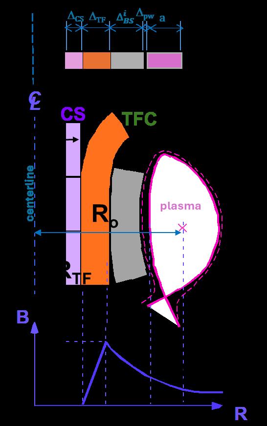
Fig. 4.2 (i) Schematic radial build of a tokamak showing the key fusion components at the inboard: central solenoid, toroidal field coils, vacuum vessel and shielding blanket; (ii) radial profile of the magnetic toroidal field that peaks at the coil. (source figure [ 15])
The fusion power in a tokamak is a func�on of: �������� ∝ ���� 2 ��������,���� 4 �������� (3)
where β has been defined above, Bt,o is the toroidal field strength at the centre of the plasma and Vp is the plasma volume. By increasing Bt,o and/or beta one clearly obtains a significant increase in power output. However, beta is limited by plasma stability and Bt,o by the maximum prac�cal magne�c field, Bt,m, at the magnet windings that is limited by technological constraints, e.g. ~13 T for Nb3Sn.
The rela�onship between Bt,m and Bt,o (see Fig. 3.1)[ 16],[ 17] is given by:
THE ROLE AND DISTINCTIVE FEATURES OF ITER
Vol.1, Ch. 4, p. 11
(4)
where A is the aspect ra�o (R/a) (A = 3.1 for ITER), R is the major radius of the plasma, and ∆����,���� is the clearance between the plasma and the first wall (roughly ~0.2 m). The parameter ∆�������� ���� is the thickness of the region occupied at the inboard by the blanket and the vacuum vessel, and includes also maintenance clearance and the thermal shield (i.e. the distance in mid-plane from the first wall to the toroidal field (TF) coil windings). The cost of the TF coils, typically, increases as ��������,���� 2
Eq. (4) clearly shows that by reducing ∆�������� ���� , for a given �������� ,���� , one can increase the value of the toroidal field strength at the centre of the plasma, and, thus, the reactor power, or for a given reactor power can reduce the machine size (i.e. R).
Similarly, the flux core radius, ������������ , for the central solenoid (CS) coils is given by (see Fig. 4.2):
where ∆ �������� ���� is the thickness of the inner TF coil leg and its support structures and ∆�������� is the thickness of the CS. For a given R, a, ∆����,���� , Bt,o, and PF, reducing ∆�������� ���� reduces also Bt,m and ∆���� and ������������ increases. Increasing ������������ reduces the ohmic hea�ng field, BCS (BCS~ 1/ R2CS). Besides the technological constraints on BCS, the cost of the CS coils, and more importantly the cost of the power supply increases rapidly with BCS
All these factors, provide a strong incen�ve to reduce ∆�������� ���� . However, providing the radia�on atenua�on in the blanket/shield necessary for magnet protec�on favours a rela�vely large ∆�������� ���� In a future device meant to produce electricity and its own tri�um, further space would be required for the breeding blanket.
The previous discussion clearly shows that the dimensioning of ITER and any other fusion device is not arbitrary but strongly linked to mission objec�ves and predefined design and opera�ng requirements. During the last 40 years, the design of ITER, its objec�ves, and design parameters have evolved because the experimental plasma physics knowledge base has on the one hand grown with the results stemming from the opera�on of several tokamak devices, the improved understanding and predic�ve capabili�es of sophis�cated simula�on codes, and the commissioning of several new devices, and on the other hand the progress in understanding has meant that some early, more op�mis�c, predic�ons of plasma performance had to be changed.
A brief review of the underlying assump�ons behind these studies clarifies the defini�on of, and the ra�onale for, the choice of ITER objec�ves and parameters.
The choice of the plasma current is one of the parameters that, for a given magnet technology, has the strongest impact on device size and capital cost. The original values set for plasma currents were based on the empirical scalings for energy confinement which enjoyed the widest support at that �me. In par�cular, a major driver towards moving to a higher current, as shown in Table 4.2, was the fact that in the 1980s an unfavourable dependence of the confinement �me on the hea�ng power was found in both low (L) confinement- and high [ 18] (H) confinement modes [ 19]. However, the factor of 2 increase in confinement observed in H-modes [ 20] re-opened the door for a viable fusion reactor design.
For a given plasma current, the size and cost of the device depend mainly on the plasma shape (e.g. elonga�on, triangularity, aspect ra�o), on engineering allowables, design concepts of the assembly, as well as the plant layout.
Table 4.1 shows the evolu�on of objec�ves of ITER while the evolu�on of its design parameters and performance, and its precursors is shown in Table 4.2. One can easily see that the correla�on between performance objec�ves and main parameters of the devices evolved towards increasing the size whilst maintaining similar objec�ves, as is shown below where the main objec�ves and parameters of some of these design studies are summarised.
Table 4.1 Historical evolution of ITER Objectives
Concept Design Ac�vi�es (CDA) (1988)
General
Plasma Physics
Demonstrate technologies essen�al to a reactor in an integrated system and perform integrated tes�ng of the high-heat-flux and nuclear components required to u�lise fusion power for prac�cal purposes.
Demonstrate controlled igni�on and extended burn of DT plasmas, with steady state as an ul�mate objec�ve.
Engineering Design Ac�vi�es (EDA) (1992)
Aim to keep device costs within limits comparable to those of the CDA.
Reduced Technical Objec�ves/Reduced Cost (RTO/RC)[ 21] (2001)
50% of device cost of EDA design.
Demonstrate controlled igni�on and extended burn of DT plasmas. Aim at demonstra�ng steady state opera�on.
Induc�vely driven Q≥10. Aim at steady state opera�on with Q≥5.
Concept Design Ac�vi�es (CDA) (1988)
Engineering Validate design concepts and qualify engineering components for a fusion power reactor.
Demonstrate reliability and maintainability.
Demonstrate poten�al for safe and environmentally acceptable opera�on of a power-producing fusion reactor.
Tes�ng Serve as a test facility for neutronics, blanket modules, tri�um produc�on, and advanced plasma technologies. Extract high-grade heat from reactor-relevant blanket modules appropriate for the genera�on of electricity.
Engineering Design Ac�vi�es (EDA) (1992)
Demonstrate essen�al fusion reactor technologies (e.g. superconduc�ng magnets and remote maintenance).
Operate safely and demonstrate safety and environmental poten�al of fusion power.
Reduced Technical Objec�ves/Reduced Cost (RTO/RC)[ 21] (2001)
Demonstrate availability and integra�on of essen�al fusion reactor technologies (e.g. superconduc�ng magnets and remote maintenance).
Assure safe and reliable opera�on.
Test reactor components (e.g. exhaust systems). Test reactor-relevant tri�umbreeding blankets, demonstra�ng capability leading to TBR>1 in a reactor, high grade heat, and electricity genera�on.
Test reactor components (e.g. exhaust systems). Test reactor-relevant tri�umbreeding blankets, demonstra�ng capability leading to TBR>1 in a reactor, high grade heat, and electricity genera�on.
THE ROLE AND DISTINCTIVE FEATURES OF ITER Vol.1, Ch. 4, p. 14
Opera�on Plan
Concept Design Ac�vi�es (CDA) (1988)
Two phases: a physics phase devoted mainly to achieving the plasma physics objec�ves, and a technology phase devoted to engineering objec�ves and the tes�ng programme. Machine modifica�ons within and between phases.
Engineering Design Ac�vi�es (EDA) (1992)
Basic Performance Phase (BPP) las�ng 10 years with a few thousand hours of DT opera�on, to address controlled igni�on, extended burn and steady state opera�on (using ini�al hea�ng systems), blanket tes�ng.
Enhanced performance Phase (EPP) las�ng 10 years improving overall performance (with poten�al H&CD upgrade) and conduc�ng higher fluence component and materials tes�ng. May demonstrate reactorrelevant blanket.
Implementa�on of EPP depends on BPP review.
Reduced Technical Objec�ves/Reduced Cost (RTO/RC)[ 21] (2001)
~20 years opera�on. Opera�on modes should be determined having sufficient reliability for nuclear tes�ng. Lowfluence func�onal tests of blankets should be conducted early on. DEMOrelevant tests can then be conducted later in higher fluence/flux condi�ons.
A further detailed descrip�on of the evolu�on of the ITER design parameters and technical characteris�cs of the various points design is presented in Sec�on 7.1.
From Table 4.2 one can see that the weight of materials substan�ally exceeds that of the CDA device, and the overall size of ITER has increased by almost 30% from 1990 to 1994. This increase in size arose partly from the need to increase volt-seconds due to the change in objec�ves in 1992 to provide a 1,000-second induc�ve pulse, and partly from maintaining confinement capability (probability of igni�on) while adop�ng a lower, more conserva�ve value for plasma elonga�on. In addi�on, a large volume single-null lower divertor was adopted in 1992, to provide maximum space for assembly and improve the maintenance of the divertor which would have been more difficult in the double null configura�on of the CDA ITER.
Although the details of the mode of divertor opera�on were not yet provided, the concept was for a so-called “detached divertor”, i.e., a divertor designed to favour the forma�on of high density/neutral density “cloud” in front of the divertor plates, where the heat flux carried by the plasma along field lines can be dissipated by radia�on, charge-exchange other atomic processes,
figura�vely “quenching the plasma”. These processes distribute the power over the en�re surface area of the divertor channels, achieving a reduc�on of the heat flux density to the material surfaces to values that can be handled by the divertor.
This design evolu�on was substan�ated by more detailed knowledge of the plasma physics and benefited from advances of technologies. The ability and experience of the designers play a major role in iden�fying reliable and cost-effec�ve design point solu�ons, striking the right balance between innova�on and industrial prac�ce. For example, a layer-wound cable-in-conduit conductor (CICC) was adopted for the toroidal field and poloidal field coils, to allow all connec�ons to be external to the core of the tokamak. A TF Coil design bucked on the CS was adopted where the TF coils and CS are mutually supported against a bucking cylinder. This approach was intended to provide greater compactness, possibly at the cost of more difficult manufacturability and added complexity.
Divertor (SN=single null; DN=double null)
Concerning the neutron fluence and the pulse length, it was ini�ally considered that reactor relevant tes�ng of a breeding blanket would be best achieved by opera�ng ITER for a significant
frac�on of the target fluence of a reactor, i.e. about 3 MWa/m2 and a pulse length of thousands of seconds to reach sta�onary condi�ons in the thicker regions of the blanket under test. The cost versus benefit of such ambi�ous objec�ves in physics and technology was challenged at the end of 1998, when both the objec�ves and the cost effec�veness of the proposed device came into ques�on. This con�nues to be challenged as cheaper means to obtain the necessary data become apparent (see Sec�on 6.8).
The need to save in capital costs while maintaining the major programma�c goals led to a redefini�on of the ITER design parameters and machine configura�on (with a capital cost 45–50% of that of ITER 1998). A study on the Reduced Technical Objec�ves/Reduced Cost ITER (RTO/RC ITER) (see Sec�on 7.1.6) showed that reducing the technical objec�ves without changing the nature of the design was not enough on its own to achieve the 50% reduc�on in cost target. Thus, further design changes, compared to the 1998 design of ITER, would be necessary.
The main changes proposed include less demanding performance objec�ves (se�ng as a goal opera�on at Q = 10 instead of igni�on), shorter plasma induc�ve burn dura�on, higher elonga�on and triangularity to increase the plasma current for the same R, improve the density limit and the beta limit, and lower fluence. This led to the need to design a suitably robust plasma ver�cal stability to take advantage of elonga�on and triangularity, ranging from the use of a close-fi�ng passive shell to copper cladding on the vessel, and passive internal saddle coils, resul�ng with the need to use ac�ve stabilisa�on coils inside the vessel.
Addi�onal measures were implemented to reduce the machine size, including:
• the use of wedged toroidal field (TF) coils with a segmented central solenoid and poloidal field (PF) coils linked above and below the equatorial plane to handle a higher plasma elonga�on and triangularity within power supply limits;
• the need to maintain the largest plasma volume at the expense of a reduced divertor volume, increased neutron hea�ng of the TF and CS winding due to reduced shield thickness, and the elimina�on of the blanket backplate (which meant connec�ng mechanically and hydraulically the blanket modules and their coolant channels directly to the vessel);
• the need to maintain the largest possible port access at the expense of a reduced intercoil mechanical structure.
It was recognised that the ITER design variant (ITER 2001 in Table 4.2), now in construc�on, could more reliably achieve the power density and wall loading objec�ves, and thus was a more prudent development path to a reactor.
As men�oned previously, a major alterna�ve route to studying burning plasma behaviour envisages using compact, higher field experiments, which may be less expensive.
High field tokamaks, based on copper coils, have been used in the United States, Italy and Japan [ 22,[ 23] [ 24]. Concepts were also proposed, but never built, for devices like BPX (CIT) [ 25], the Fusion Igni�on Research Experiment (FIRE) [ 26], and IGNITOR [ 27], [ 28] to explore high-Q opera�on and possibly igni�on. The main mo�va�on behind the choice of high field has been to explore the physics of regimes with a high nTτe parameter in limited size and cost experiments. High magne�c fields in a reduced size support designs with higher plasma current and density although at lower confinement �me.
The poten�al downsides of this approach are the higher heat loads expected on the divertor. New divertor solu�ons with performances well beyond today’s concepts would be needed and complex mechanical and electrical engineering provisions must be adopted. For example, higher field windings generate higher forces in the mechanical structures in and around the plasma, in par�cular in the toroidal field (TF) coils, which cons�tute the structural core of the machine. The stresses on the inboard leg of the TF coil casing tend to quickly reach the maximum allowable stress for a given geometry, effec�vely limi�ng the field. This stress roughly scales with B2/S (where S is cross sec�on of the structural elements).
Copper coils, even cooled at liquid nitrogen condi�ons to lower copper resis�vity and increase strength, have a limited pulse dura�on of a few seconds or tens of seconds, due to the high electric power required to sustain the extremely high currents and current densi�es in the windings.
Recently, a new interes�ng route has emerged with the advent of high temperature superconductors (HTSs) that offers the promise of opera�ng at higher magne�c field and temperature for longer pulses. This allows the use of higher field magnets and has then been promoted by several groups around the world to substan�ally reduce the size of a fusion power reactor system and as a breakthrough innova�on that could drama�cally accelerate fusion power deployment. There are some major challenges though, including making sure that the higher electromagne�c forces resul�ng from the increased field can be accommodated by the magnet structure and that the reduced reactor size s�ll provides sufficient space for the required shielding of the magnets and other components, which, even for a reactor the size of ITER, had proven to be very problema�c.
Main concerns in the case of a thin-film type HTS, which is currently used, are uncertain�es in terms of the performance required for tokamak reactors, such as whether it can operate stably enough against magne�c loads, alterna�ng current losses and disturbances in a complex magne�c field and nuclear irradia�on environments, whether it can provide the precise magne�c field profile necessary for plasma shaping and opera�on, and whether it can accurately and quickly detect abnormali�es (quench detec�on) in the superconduc�ng state for its protec�on. The discoveries and innova�ons in HTS that have brought them into such considera�on have occurred a�er the consolida�on of the ITER magnet design. In the future, such a technical basis may be available. Nevertheless, HTSs are used to reduce heat losses occurring when conven�onal power supply lines are connected to the superconduc�ng terminals of ITER's magnets.
At present, ITER is the largest tokamak being built to produce fusion energy by confining a deuterium-tri�um plasma in which the α-par�cle hea�ng dominates all other forms of plasma hea�ng. Its primary mission is to regularly sustain a DT plasma producing ~500 MW of fusion power for dura�ons of 300–500s with a ra�o of fusion output power to input hea�ng power, Q, of at least 10. ITER is also designed to explore the physics basis for the con�nuous opera�on of fusion power plants by inves�ga�ng ‘steady state’ plasma opera�on by means of non-induc�ve current drive for periods of up to several thousand seconds while maintaining a fusion gain, Q, of ~5. The project’s technical goals encompass significant technological demonstra�ons to prepare the design basis for a tokamak fusion power plant. One of the most important awaited demonstra�ons is that of breeding blanket modules that are inserted in a limited number of properly equipped equatorial ports.
These tests are considered essen�al in evalua�ng the performance of the various op�ons to be tested and confirming the feasibility of tri�um self-sufficiency and the extrac�on of tri�um and high-grade heat. Achieving tri�um self-sufficiency will be an inescapable requirement for any nextstep fusion facility beyond ITER. However, no fusion breeding blanket has ever been built or tested. Hence, to ensure its crucial integrated func�ons and reliability in DEMO and future power plants, ITER presents a first and unique opportunity to test the response of representa�ve component mock-ups, specifically called Test Blanket Modules (TBMs) at relevant opera�ng condi�ons, in an actual fusion environment, albeit at very low neutron fluences (see Sec�on 6.8)
ITER is a long-pulse tokamak with elongated plasma shape and single null poloidal divertor located at the botom of the vacuum chamber. The ITER design is based on scien�fic knowledge and extrapola�ons derived from the opera�on of tokamaks over the past decades and on the technical know-how flowing from the fusion technology R&D programmes around the world.
The design has been validated by wide-ranging physics and engineering work, including detailed analyses, specific experiments in exis�ng fusion research facili�es and dedicated technology developments and tests.
The major components of the tokamak are the superconduc�ng toroidal and poloidal field coils which magne�cally confine, shape and control the plasma inside a toroidal vacuum vessel. The magnet system comprises toroidal field coils, a central solenoid, external poloidal field coils, and correc�on coils. The superconduc�ng magnets are cooled with helium at 4.5 K. The toroidal field coil windings are enclosed in strong mechanical containment structures. The vacuum vessel is a
double-walled structure with water filled between the walls to provide cooling and radia�on shielding capabili�es.
The magnet system and the vacuum vessel, together with internals, are supported separately by the so-called gravity supports. Inside the vacuum vessel, the internal, replaceable components, including blanket modules, divertor cassetes, and port components such as the hea�ng antennas, test blanket modules, diagnos�c modules, and/or port plugs, absorb the radiated heat as well as most of the neutrons from the plasma, protec�ng the vessel and magnet coils from excessive heat and damage by nuclear radia�on. The heat deposited in the internal components and in the vessel is removed from the vessel via the tokamak cooling water system. The en�re tokamak is enclosed in a cryostat, with thermal shields between the hot components and the cryogenically cooled magnets.
During plasma start-up, low-density gaseous fuel will be introduced into the vacuum vessel chamber by the gas injec�on system. The plasma will progress from a circular configura�on to an elongated divertor configura�on as the plasma current is ramped up. As the current develops (nominally up to 15 MA), subsequent plasma fuelling (gas or pellets) and addi�onal hea�ng leads to a high energy gain burn and finally to a controlled burn with a fusion power of about 500 MW. With non-induc�ve current drive from the hea�ng systems, it is envisaged that the burn dura�on will ul�mately be extended towards 3000 s. In induc�ve scenarios, before the induc�ve flux available has been fully used, reducing the fuelling rate to slowly ramp-down the fusion power terminates the burn. This phase is followed by plasma current ramp-down and finally by plasma termina�on. The induc�vely driven pulse has a nominal burn dura�on of 300 to 500 s, with a pulse repe��on period as short as 1800 s.
Fig 4.3 shows a cutaway of the ITER Tokamak while some key ITER figures, the main ITER systems, and the main opera�on phases are summarised in Tables 4.3, 4.4 and 4.5, respec�vely.
Table 4.3: Some key figures about ITER
• The ITER Tokamak is the largest ever built, with a plasma volume of 840 m3. The maximum plasma volume in tokamaks opera�ng today is 160 m3 reached in Japan's JT-60SA;
• The ITER tokamak weighs 23,000 t, the equivalent of three Eiffel Towers;
• The ITER vacuum vessel measures 19.4m across (outer diameter), 11.4 m high, and weighs approximately 5,200 t of which 1,611 t is the vacuum vessel, 1733 t for the shielding plates, 1781 t for the ports and 111 t for the supports. With the installa�on of the blanket and the divertor, the vacuum vessel will weigh 8,500 t. Its double wall thickness varies from 0.34 m at the inboard to 0.75 m at the outboard. The internal surface of the vacuum vessel is 850 m2 and it has a volume of 1400 m3. The double-walled structure is filled with water to provide cooling and radia�on shielding capabili�es;
• The structure of the ITER central solenoid, the large, 1,000 t electromagnet in the centre of the machine, must be strong enough to contain a force equivalent to twice the thrust of
a space shutle at take-off: 60 MN, or over 6,000 t of force. The CS coils produce induc�ve flux to ramp up and maintain the plasma current and contribute to shaping the plasma. In ITER the CS is made of six independent Nb3Sn modules, with a total height of 13 m, a diameter of 4 m and a total weight of about 1000 t. The maximum opera�ng current in the CS modules is 45 kA, leading to a maximum field of 13T reached in the centre of the stacked modules and a magne�c energy stored in CS coils of 7 GJ. This generates sufficient magne�c flux to allow ini�a�ng and sustaining a plasma current of 15 MA for about 400 s under burning plasma condi�ons;
• Every one of the ITER's 18 D-shaped Nb3Sn toroidal field coils is 17 m high and 9 m. wide and weighs 360 t (the approximate weight of a fully loaded Boeing 747-300 airplane), distributed among its components: 110t for the winding pack, 190 t for the casing and 60t for pre-compression systems, shear keys and bolts. The total magne�c energy in the TF coils is around 40 GJ. The current flowing in the TF conductors is 68 kA, which produces a maximum magne�c field of 11.8 T on the coil;
• The PF coils control the radial posi�on of the plasma, contribu�ng to its stability by maintaining the clearance between the plasma and the first wall. PF magnets are also essen�al elements of the slow ver�cal posi�on control and of the plasma shaping capability. In ITER the six annular NbTi PF coils are located outside of the TF magnet structure. They are designed to operate at a maximum current of 45 kA, which generates a maximum magne�c field of 6 T on the coils and a total magne�c energy of 4 GJ. The largest magnet has a diameter of 24 m and the heaviest is 400 t, with a total combined weight of 2,163 t. All of the coils men�oned above are toroidally symmetric;
• Some 400,000 t rests on the lower basemat of the Tokamak Complex including the buildings, the 23,000 t machine and equipment. This is more than the weight of New York's Empire State Building.
• The Tokamak Building is slightly taller than the Arc de Triomphe, Paris. Measuring 73 m (60 m above ground and 13 m below), it is the tallest structure on the ITER site.
• The main feature of the 180 ha ITER site in Saint Paul-lez-Durance, southern France, is a man-made level pla�orm that was completed in 2009. This 42 ha pla�orm measures 1 km long by 400 m wide, and compares in size to 60 football fields.


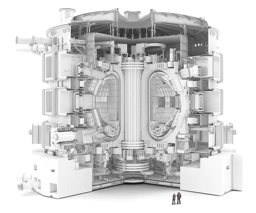
Fig. 4.3 Cutaway view of the ITER tokamak (numbers shown refer to some key components/systems, as listed in Tab. 4.4)
Table 4.4 Main ITER systems
1. Magnets
a. Toroidal Fields Coils (18)
b. Poloidal Fields Coils (6)
c. Central Solenoid (6)
d. Pre-Compression Rings (6)
e. Correc�on coils (18)
f. In-vessel coils for VS and ELM control.
2. Vacuum Vessel (9 sectors)
3. Cryostat
4. In-Vessel
a. Shielding Blanket
b. Divertor
5. Auxiliary Hea�ng Systems
a. Neutral Beam
b. EC launchers
c. RF Antennas
6. Diagnos�cs
7. Fuel Cycle
8. Remote Handling
9. Test Blanket Modules
The ITER plan (baseline 2024) foresees three main opera�on phases: 1) Start of Research Opera�on (SRO); 2) First Deuterium-Tri�um phase (DT-1); and 3) Second Deuterium-Tri�um phase (DT-2). Each opera�onal phase is preceded by integrated commissioning phases aimed at ensuring that each of the components and plant systems installed during the tokamak assembly phase or upgrade has been installed correctly. It is also an opportunity to transfer knowledge to the
THE ROLE AND DISTINCTIVE FEATURES OF ITER Vol.1, Ch. 4, p. 22
opera�ons team, test all the procedures, sa�sfy any licensing requirements, and get ready to start the first experiments.
With the advent of the ITER baseline 2024 [ 29][163], the opera�on strategy is based on the progressive acquisi�on of knowledge, combining a stepwise approach to demonstra�ng nuclear safety with the stepwise approach to opera�on, based on several phases: two first opera�onal phases (SRO & DT-1) with limited nuclear safety stakes, cons�tu�ng learning phases for the acquisi�on of data on systems and components, and a third opera�onal phase (DT-2) with the target of achieving all the goals of the Project Specifica�on, which will then be fully established on the basis of the results of the first two phases.
Table 4.5 Main ITER Operation phases
Start of Research Opera�on (SRO): This phase starts with the demonstra�on of the first tokamak plasma and concludes with the demonstra�on of tokamak opera�on up to the nominal design parameters of 15 MA / 5.3 T in a diverted plasma configura�on, including the use of the electron cyclotron (EC) and ion cyclotron (IC) hea�ng and current drive (H&CD). Within the SRO phase an experimental campaign with deuterium plasmas at reduced current up to 7.5 MA and toroidal field (2.65 T) will take place to explore the opera�onal space and control of H-mode plasmas in ITER. This deuterium campaign will have a limited neutron budget (~1.5 1020) to allow entry of personnel into the vacuum vessel for installa�on of components in the post-SRO shutdown. Risks of damage to the water-cooled blanket in-vessel components are removed by installing in their stead a temporary iner�ally cooled first wall. This will allow the full characterisa�on of disrup�on loads, the valida�on of safety-related assump�ons, and the commissioning of the disrup�on mi�ga�ons system up to full magne�c energy (15 MA / 5.3 T). Since the first wall is iner�ally cooled (the divertor is water cooled) the dura�on of the flat top with high hea�ng power levels will be limited to about 30–50 s. In essence, in this phase, the engineering evalua�on of the ITER tokamak as an integrated system with as-built and asassembled components/systems will be performed. The SRO phase is foreseen to last 27 months. The post-SRO phase for assembly and commissioning towards DT-1is envisaged to last less than 36 months.
First Deuterium-Tri�um opera�on phase (DT-1): In this phase, DT plasma scenarios will be developed to demonstrate the atainment of the key project goal of 500 MW of fusion power with a mul�plica�on factor Q ≥ 10 for lengths of at least 300 s and to demonstrate high-duty opera�on (i.e. one pulse every 30 minutes) with fusion power levels of 250 MW for at least 300 s. Research in this phase will address, amongst others, a wide range of burning plasma physics and scenario integra�on issues, and will provide demonstra�ons of key technologies required for demonstra�on fusion reactors, including the installa�on and tes�ng of four test blanket systems as planned by the ITER TBM Program. The neutron fluence in this phase will be limited to ~1% of the ul�mate project fluence goal (~ 3.5 1025 neutrons) to enable the performance of ex-vessel maintenance ac�vi�es, while respec�ng the specified shutdown dose
rate requirements for workers. This phase will provide key reference data to confirm safetyrelated evalua�ons for DT Opera�on in ITER (e.g. radia�on maps, T reten�on and removal, dust produc�on etc.), which will be used to define the details of the licensing requirements in the DT-2 opera�on phase. We note that, while the neutron produc�on in this phase is limited, it is high enough to require the use of remote handling tools to perform in-vessel shutdown ac�vi�es in DT-1. The DT-1 opera�on phase is foreseen to last up to 10 years to include five experimental campaigns.
Second Deuterium-Tri�um opera�on phase (DT-2): In this phase, DT plasma scenarios will be developed to demonstrate all the project’s fusion power produc�on goals. These goals are specifically: the demonstra�on of 500 MW of fusion power with fusion power mul�plica�on factor Q ≥ 10 for lengths of 300-500 s in high duty opera�on and of long pulse and steady-state scenarios with Q ≥ 5 and burn lengths of 1000 s and 3000 s respec�vely, as defined in the Project Specifica�ons and Project Requirements [5]. In addi�on, research will be carried out to support the ITER Members’ demonstra�on fusion reactor programmes including both scenario development issues (e.g. heat flux exhaust), design/opera�onal issues (e.g. op�mum H&CD mix) and their TBM programs, in principle, up to neutron fluences of at least 0.3 MWa/m2.
Before the start of DT-2 specific integrated commissioning of the newly available or upgraded components or systems and recommissioning of the exis�ng ones will take place. The DT-2 phase is foreseen to last up to 10 years to include five experimental campaigns. Table 4.4 summarises key tokamak components and systems that will be available to execute the programme in each of the phases. The successful implementa�on and execu�on of the ITER Research Plan rely on close collabora�ons among the ITER Organiza�on and the ITER Member’s fusion research ins�tutes in both the experimental and theory/modelling areas.
Table 4.4 shows key tokamak components/systems available to execute the programme in each of the phases described in table 4.5.
Table 4.5 Main Tokamak components and systems in each of the phases.
System/ Ancillary Available
Vacuum Vessel, Thermal Shield and Cryostat Final Config. Final Config. Final Config.
Toroidal Field, Poloidal Field, Central Solenoid and Error Field
Correc�on Superconduc�ng Magnets and Power Supplies Final Config. Final Config. Final Config.
In-vessel Ver�cal Stability and ELM Control Coils and Power Supplies Final Config Final Config. Final Config.
Cryostat and Torus
Cryopumps
Disrup�on Mi�ga�on System Final Config. Final Config. Final Config.
Electron Cyclotron Hea�ng Upper Launchers installed, 3 opera�onal 1 Equatorial Launcher (40 MW)
3 or 4 Upper Launchers opera�onal 2 Equatorial Launchers (60–67 MW)
3 or 4 Upper Launchers opera�onal 2 Equatorial Launchers (60–67 MW)
Ion Cyclotron Hea�ng 1 Antenna (10 MW) 1 Antenna (10–20 MW) 1 Antenna (10–20 MW)
Neutral Beam Hea�ng 2 Injectors (33 MW)
2 or 3 Injectors (33–49.5 MW)
System/ Ancillary Available
Blanket Shield Modules and First Wall Temp. Config. iner�ally cooled Final Config. Final Config.
System/ Ancillary Available
Diagnos�c Neutral Beam Final Config. Final Config.
Divertor Final Config. Final Config. Final Config. Diagnos�cs
Basic set for SRO phase (incl. for the safetyrelated knowledge acquisi�on programme) Near complete set, including DT fusion products Complete set
Glow Discharge System Par�al Config. Final Config. Final Config. Hot Cell Facility Par�al config. for opera�on on TFA liquid radwaste, independent ly of HC building opera�onal for DT-1 opera�onal with expanded capabili�es for DT-2
Boronisa�on
Gas Distribu�on (B2D6) Final Config. Final Config. Final Config.
Gas and Pellet
Test Blanket Modules
TBMs DT-2 TBMs
Injec�on Systems Par�al Config. Final Config. Final Config. Tri�um Plant opera�onal opera�onal with expanded capabili�es for DT-2
The complexity of a fusion power plant like ITER, with regard to integra�on of plant systems, is much higher than that in a fission power plant due to the larger number of plant systems.
The general plant architecture is arranged around the tokamak, with a cylindrical bioshield of 2 m thickness around the cryostat, and floor levels corresponding to the cryostat penetra�ons. Addi�onal levels are used for the integra�on of auxiliary equipment for the various plant systems and for accident mi�ga�on systems. Currently, the tokamak building also represents a final nuclear
AND DISTINCTIVE FEATURES OF
confinement barrier for the radioac�ve material towards the environment and the public. This safety func�on requires the plant and safety systems to limit the release of radioac�ve substances during normal opera�on and in accidental condi�ons well below the safety limits.
Furthermore, fusion is a nuclear technology and as such will receive scru�ny from regulators under relevant principles such as ALARA (risks As Low As Reasonably Achievable). This means that licensing considera�ons related to shielding, safety, and remote handling (RH) must be considered from the outset and can play a significant role in the design. Final assessments in this area can only be conducted once engineering design details have been developed and thus require a certain maturity of design. When the decision to site ITER in France was taken in 2005, a commitment was taken to observe all French regula�ons. By virtue of its tri�um inventory, ITER falls in scope of nuclear licensing as an INB along with fission reactors and other facili�es with a radioac�ve material inventory. It is therefore regulated by the Nuclear Safety Authority and Radioprotec�on (Autorité de Sûreté Nucléaire et de Radioprotec�on, ASNR) and subject to the provisions of the nuclear transparency law (TSN law).
More recently, discussions in some countries and at the IAEA have considered the approach to the licensing of fusion power plants in the future. In some cases, notably the USA and the UK, it is foreseen that fusion plant will not be licensed under exis�ng nuclear regula�ons intended for fission reactors, but under new regula�ons that will be propor�onate to the reduced risks presented by fusion. In the UK, this posi�on has been enshrined in law. However, these developments have come too late to influence the licensing of ITER, which remains under exis�ng French nuclear regula�ons. This subject is further discussed in Chapters 8 and 10.
The ITER goals, especially for the pulse lengths, duty cycles, and availabili�es, represent a very large extrapola�on from current experience and place a large demand on design integra�on, power handling, neutron shielding, component reliability, and maintenance procedures.
The essen�al differences between the atainments of today’s tokamak research facili�es and what should be achieved in ITER are summarised in Table 4.6 together with the related primary issues. The increase in fusion power and in plasma energy content together with the increase in pulse dura�on and cumula�ve run �me represent the largest changes in opera�on condi�ons in ITER. These will have by far the greatest consequences, giving rise to important effects, which are only par�ally observed and accessible in present day experiments, and will provide new physics insight, and open new design, opera�on and safety issues.
A new class of important medium- and large-size devices that rely on the use of superconduc�ng magnets is now in opera�on within ITER Member countries. They include for example the Large Helical Device [ 30] in Japan, the stellarator Wendelstein 7-X [ 31] in Germany, and several tokamaks, including WEST [ 32] in France, KSTAR [ 33], [ 34] in Korea, EAST [ 35], [ 36] in China and JT-60SA [ 37] in Japan. They rou�nely operate with long pulses and require the use of ac�vely cooled components. However, many present-day machines s�ll operate with copper-coils and in short pulse mode, with plasmas maintained for periods of the order of seconds, typical pause �mes of 5–30 minutes and power loads sufficiently low to be handled by iner�al cooling.
In present-day tokamak devices, erosion of the main chamber wall and divertor strike plates act as a source of impuri�es in the discharge but does not affect the component life�me, mainly because of the very low duty cycle. Erosion effects are on the scale of microns for a typical run campaign (1,000–5,000 s/opera�on year) [ 38]. Similarly, fuel economy has never been an issue in deuterium fuelled experiments, and only in the late 1990s have the limita�ons associated with the use of tri�um and its incomplete recovery in experiments in TFTR [ 39] and JET [ 40] brought the issue of fuel reten�on under closer scru�ny. In contrast, long plasma dura�on and high duty cycle opera�on in a next step device such as ITER will lead to levels of erosion/redeposi�on and tri�um reten�on that could affect opera�onal availability, due to the necessity of tri�um removal and/or divertor plate replacement. Also, divertor heat loading caused by disrup�ons and Type-I ELMs would imply mel�ng/abla�on for any material in the divertor weted by the plasma.
Two of the main challenges pertaining to the large amount of tri�um and need to control the invessel tri�um inventory, and the problem of plasma transients and their mi�ga�ons, are briefly described below.
Table 4.6. Distinctive features of ITER and main differences with existing devices
1) High energy content (several hundreds of MJ vs. few MJ in current devices) and power flow (several hundred MW in the scrape-off-layer (SOL) vs. tens of MW in current devices):
• more intense disrup�ons and disrup�on-related damage effects (e.g., material abla�on and mel�ng) resul�ng in local damage and in a substan�al influx of impuri�es into the plasma;
• ver�cal displacement events (VDEs) will produce much larger forces on vessel components in ITER than in present day tokamaks. As the plasma column moves during a VDE, a substan�al frac�on of the plasma current is transferred to a “halo” region around the main plasma. Since the halo intersects the vessel wall, the return path for this “halo current” passes through conduc�ng components of the vessel structures. The flow of this return current will be perpendicular to the main magne�c field, thus exer�ng a large mechanical force on these structures;
• high electric fields produced by disrup�ons can also give rise to produc�on of run-away electrons with mul�-MeV energy. There are s�ll substan�al uncertain�es related to the
runaway current that is predicted to be much larger in ITER due to the avalanche effect, and to the quan�fica�on of material damage effects; the database from tokamaks is somewhat limited in this respect.
• plasma power densi�es for long dura�ons in the divertor will be larger than in presentday experiments and require an effec�ve and reliable way to disperse the power on the divertor surfaces.
• type-I ELMs will, if unmi�gated, cause mel�ng/abla�on of any material in the divertor weted by the plasma
2) Long pulse dura�on (few hundred seconds vs. few seconds in most of current devices):
• requires ac�ve cooling of PFCs and vessel structures, and techniques to pump helium ash during each pulse;
• requires effec�ve control of plasma purity and plasma-wall-interac�ons to achieve high plasma performance.
3) High duty factor or pulse repe��on rate (ultimately needed for meaningful breeding blanket testing in the second phase of operation)
• high performance plasma opera�on with limited shutdown �mes for wall condi�oning and tri�um recovery;
• effec�ve and fast remote maintenance to minimise shutdown �mes.
4) Long cumula�ve run �me (several thousands of hours of operation over several calendar years):
• the erosion life�me of PFCs may be sufficiently short that several replacements will be required during the life�me of the device;
• large-scale erosion also raises tri�um reten�on and dust (safety) issues that may determine the feasibility of reactor designs
• neutron damage effects in the bulk of surrounding materials and structures;
• plasma-facing surfaces will be modified in situ by the plasma, which will mix the plasma-facing materials. The composi�on, physical structure, and proper�es of deposited materials will be different to manufactured materials.
5) Rou�ne opera�on with large amount of tri�um (10–100 g/pulse vs. fractions of g in current devices):
• this requires a closed fuel cycle with efficient reprocessing of the exhaust stream (e.g., limited but successful opera�on experience of TFTR and JET);
• requires adequate tri�um supply, minimisa�on of the inventory of tri�um retained on in-vessel components and efficient methods of recovery;
• address safety concerns of any vulnerable tri�um inventory.
6) Superconduc�ng magnet technology
• a thick neutron shield is required to protect the toroidal and poloidal coils, thereby increasing the major radius and the overall size of the device; neutron and gamma irradia�on destroy organic insulators and superconductors, and also increase the resis�vity of the stabilising Cu (typical limit is <109 rad);
• since the superconduc�ng magnets will remain energised during the interval between pulses, certain techniques used in tokamaks for between-pulse wall prepara�on/condi�oning will not be feasible.
7) Fast remote maintenance for repair/refurbishment of the in-vessel and some of the exvessel components:
• viability of remote methods of maintenance, repair and upgrading of fusion devices, is a key technology for development of fusion reactors (e.g., limited but very successful experience at JET);
• requires a specific system, component and sub-component design philosophy to minimise shut-down �mes (effec�ve remote maintenance and repair), and to meet stringent constraints imposed by a radioac�ve environment.
8) Safety
• requires stringent and detailed safety assessments and safety-related procedures and controls, par�cularly once components have become ac�vated and changes (in components or their opera�on) need to be made;
• stringent worker and public radia�on protec�on measures;
• public outreach to address community acceptance and understand safety and risk in context.
Control of the in-vessel tri�um inventory - Safe management and accoun�ng of tri�um is recognised to be crucial for the acceptance of fusion as an environmentally benign power source. Tri�um reten�on in co-deposited materials from PFCs and dust forma�on and accumula�on have emerged as a primary concern for ITER, with strong implica�ons for in-vessel component design, material selec�on, opera�onal schedule and safety. Special controls imposed on the handling of tri�um require that the quan�ty of tri�um retained in the torus be accounted for, and the inventory limited in order to permit con�nued opera�on within the licensed site inventory limit.
An excessive tri�um inventory in the torus would present a safety hazard in the form of a poten�al tri�um release to the atmosphere in case of a loss-of-vacuum event. Besides tri�um inventory control, tri�um removal from the wall is required to control plasma fuelling by tri�um implanted in the wall and to reduce the tri�um outgassing. Independently of safety limits, control of the invessel tri�um inventory is also necessary to manage the available tri�um supply. Tri�um reten�on
mechanisms are reviewed elsewhere (see for example [ 41]). Table 4.7 shows a list of key quan��es related to tri�um in exis�ng tokamaks and ITER [40].
Tri�um reten�on and the control of the tri�um inventory in ITER have been key drivers for the choice of plasma-facing materials and their opera�onal condi�ons. Experimental results in the 90 s [40] showed very large reten�on of tri�um co-deposi�on with carbon, and the need to mi�gate/control tri�um accumula�on via co-deposi�on in the torus. Reten�on by other mechanisms such as implanta�on and surface adsorp�on, which may be significant for small, short pulse machines, is expected to rapidly reach satura�on in ITER.
The experimental results with tri�um fuel for the plasma led to the decision to abandon carbon and choose a beryllium (wall) and tungsten (divertor) combina�on as alterna�ve solu�ons for the PFCs of ITER. Considera�on on beryllium toxicity, its low mel�ng point and risk of severe damage has now led to another change in the PFC materials for ITER, that is to use tungsten both in the divertor and in the first wall (See Vol.2 [ 42]). The recent DT JET-ILW experiments have indeed demonstrated a ten-fold reduc�on of fuel reten�on rates in deuterium compared to reference pulses in JET-C [ 43]. Furthermore, first results of ASDEX-Upgrade with a full tungsten wall and divertor have demonstrated reduced D fuel reten�on compared to C-dominated condi�ons in 2007-2008 44[.
discharges
# of tri�um
T inventory in the torus and NBIs (g)
reten�on (excluding
Increment of tri�um inventory (g)
T removed during clean-up period (g)
(g)
in the
a) This is an average value over the period of 1993–97, excluding dedicated tri�um removal campaigns.
b) This was the tri�um inventory in all systems outside the ac�ve gas handling system (AGHS) (i.e. neutral beam injectors (NBI), torus), but individual analysis of batches of gas from the different subsystems indicate that the torus contributes >90% of the inventory.
c) Some cleanup was also done in the middle of DTE1, to repair a small water leak in the fast shuter of the neutral beam. At that �me 11.4 g of T2 had been introduced into the torus and about 4.6 g of tri�um was retained on the walls. The wall load was reduced to 2.3 g in a four day period with ∼120 pulses.
d) During T and DTE2 campaigns, JET opera�ons were restricted by a daily limit of 11 g (44 bar-l) of tri�um on the inventory allowed in torus and cryo-panels (divertor and neutral beams), as set by the JET D-T safety case.
e) In total, ~2 g / T were removed from JET PFCs during the clean-up sequence.
f) The in-vessel tri�um inventory a�er the DTE2 and T campaigns at this date remains unquan�fied. In the absence of post-mortem analysis of JET PFCs one can only provide an upper bound es�mate of T reten�on in JET with Be/W wall, based on results from gas balance analysis of D fuel reten�on from earlier campaigns, which yielded a 2% fuel reten�on frac�on. These results need to be compared with the large T reten�on measured in JET with C-wall a�er DTE1: ini�al T inventory of 40% of the injected amount of T of 35 g, decreasing to ~17% (~6g of T) a�er days of tokamak plasma opera�on in deuterium.
g) Design requirement.
Mi�ga�on of disrup�ons and other off-normal transients - The main characteris�cs and the resul�ng consequences of off-normal transients in ITER are summarised in Table 4.8.
Table 4.8 Type, range of parameters chosen to design ITER components and major consequences of plasma transient events in the ITER design.
Event Key Characteris�cs Major Consequence(s) and/or comments(s)
Major disrup�ons frequency: ∼10%;
thermal energy ≈ 0.35 GJ
thermal quench �me: 1–
10 ms;
magne�c energy ≈ 0.6 GJ
current quench �me: 50–
1000 ms;
max. current decay rate:
500 MA / s
VDE(*) dura�on ≈ plasma quench; direc�on = up or down (depending on changes of plasma current and inductance); halo current ≤40%.
vaporisa�on (and also mel�ng for metals) of divertor targets, and nearby surfaces;
during the thermal quench, 80–100% of the thermal energy (Wth) is transported by conduc�on to divertor; ≤30% by radia�on to first wall or baffle;
during the ensuing current quench phase; most of the remaining magne�c energy , about 600 MJ (only a frac�on of the poloidal field energy) is conducted to the wall and can lead to mel�ng. ini�ates VDE and runaway conversion
follows each disrup�on; slow current quench > worst VDE; part of the magne�c energy (Wmag) is lost to the first wall; produces in-vessel halo currents and forces on in-vessel components
Loss of equilibrium control VDEs frequency: 1% of pulses dri� ≈ 1–5 s to wall contact onset: first wall contact ini�ates H mode loss, Wth ini�ated by poloidal field control failure; electromagne�c effects (halo currents/ver�cal forces);
Event Key Characteris�cs Major Consequence(s) and/or comments(s) loss, mel�ng, rapid current quench or disrup�on
major thermal effects on first wall; affected first wall region: upper/inside or divertor entrance
Runaway current conversion knock-on avalanche
E ≈ 10–15 MeV, Wth ≈ 60 MJ (uncertain)
many uncertain�es; toroidal localisa�on depends on first wall alignment; shutdown species will influence runaway electron current Fast shutdown (ac�ve control)
τth , τmag ≤ 1 s; by impuri�es and H/D injec�on.
Type I ELMs frequency: 2–0.5 Hz, ∆Wth /Wth ∼ 2–6 % deposi�on �me: 0.1–1 ms;
fast plasma power and current shutdown means for thermal protec�on of the first wall and divertor targets; by impurity and D injec�on, D favoured to minimise runaway conversion.
∼50–80 % of the energy lost from the core plasma is observed to strike the divertor target (e.g. in DIII-D, ASDEX-Upgrade);
JET, DIII-D, ASDEX-Upgrade reported inboard energies;
2–4 �mes that on outer divertor (see text for further details).
(*) During a VDE, the ver�cal plasma movement precedes the thermal quench; during a major disrup�on, the thermal quench precedes the ver�cal movement
To offset the effects of thermal transients, the ITER design incorporates several specific technologies to control, mi�gate or suppress the principal instabili�es, i.e. neoclassical tearing modes (NTMs), edge-localised modes (ELMs), resis�ve wall modes (RWMs), ver�cal instabili�es and major disrup�ons. It has, for example, been established for many years that NTMs can be stabilised by using localised Electron Cyclotron Current Drive (ECCD) to suppress the growth of the tearing mode island (e.g. [ 45], [ 46], [ 47]). The ITER Electron Cyclotron Hea�ng (ECH) system includes four EC launchers located in the upper port plugs specifically for this applica�on.
The need to enhance ITER’s control capability for other forms of MHD instability and to improve the reliability of opera�on has mo�vated significant R&D studies which have provided the physics basis for several design changes incorporated during the past decade. To ensure more robust control of the plasma ver�cal posi�on, a pair of in-vessel coils, one located near the top of the
vacuum vessel and the other located on the lower half of the outboard vessel wall, is included in the design. These coils, coupled in a “saddle-coil” arrangement, enhances the ver�cal stabilisa�on capability by adding a second fast-response circuit to that provided by the external superconduc�ng PF coils. This will allow a significantly more rapid response to fast changes in plasma ver�cal posi�on and will ensure that ver�cal excursions of the plasma having a larger ini�al displacement, for example in response to fast changes in plasma β or internal inductance, can be controlled reliably [ 48], [ 49].
A second set of in-vessel coils has been incorporated to address the challenge of ELM control: the transient heat and par�cle fluxes associated with large amplitude ELMs in the ITER reference plasma scenario can lead to localised mel�ng or significant erosion of the PFCs, in par�cular, of the divertor high heat flux components, reducing their opera�onal life�me (see for example [ 50]). It is, therefore, necessary to reduce the heat pulse caused by ELMs by more than an order of magnitude, or to fully suppress the ELMs, while retaining the high plasma performance characteris�cs of the H-mode. On the other hand, ELMs can also play a beneficial role in controlling the influx of tungsten sputered from the divertor, helping to limit the tungsten concentra�on in the plasma core. Controlling the ELM instability-driven transport and intrinsic transport processes in the plasma edge pedestal to achieve the required benign condi�ons, presents a challenging problem.
Following ini�al experimental demonstra�ons of ELM suppression by magne�c perturba�ons in DIII-D [ 51], [ 52], a set of in-vessel ELM control coils was incorporated in the ITER design from 2007 to complement the pellet pace making capability previously foreseen, which exploits high frequency injec�on of cryogenic deuterium pellets to generate high frequency/low amplitude ELMs (see for example [11], [69]). This combina�on of techniques provides greater flexibility in addressing ELM control/suppression in ITER burning plasma opera�on. The ELM control coil array consists of 27 coils mounted on the outboard wall of the vacuum vessel in a toroidal/poloidal array of 9 – 9 – 3 coils. It is also foreseen that the power supplies for this coil array can be upgraded during the ITER Opera�ons Phase to provide a capability for RWM control.
Disrup�on mi�ga�on on the ITER scale must be highly reliable and efficient to ensure that the design life�me of in-vessel components can be met. Even in the first phases of opera�on, the energies stored in the plasma are sufficient to cause the mel�ng of plasma facing components.
Thermal energies above 25 MJ are expected to cause localised mel�ng of divertor �les during a disrup�on thermal quench and magne�c energies associated with currents above about 6 MA can produce localised mel�ng of first wall components during unmi�gated current quenches. In addi�on, the probability of genera�ng runaway electrons increases with plasma current and at 15 MA a seed runaway popula�on at the end of the thermal quench of the order of 103 electrons may already be cri�cal. Indeed, on the basis of present knowledge, runaway electrons generated in ITER during a 15 MA disrup�on have the poten�al to deposit a total energy of up to hundreds of MJ on the first wall, the divertor dome and/or the outer divertor baffle.
Failure to suppress runaway electron genera�on, or achieving insufficient mi�ga�on, will result in significant damage to plasma-facing components, including a risk of water leaks. The common concept of disrup�on mi�ga�on is to dissipate the energy through line radia�on on the �mescale of the disrup�on. While there is confidence that this concept is in principle able to reduce conduc�ve heat fluxes and electromagne�c loads, there are large uncertain�es for other aspects of disrup�on mi�ga�on. Most important will be to ensure that runaway electron forma�on is excluded when mi�ga�ng thermal and electro-magne�c loads.
Designing a disrup�on mi�ga�on system (DMS) that fulfils this essen�al requirement requires much beter understanding of the genera�on of runaway electron seed popula�ons during the MHD driven thermal quench than exists at present (see Sec�on. 6.6). It is expected that increasing the density over the en�re plasma cross-sec�on will be essen�al. This can only be achieved with sufficient understanding of the material penetra�on process and how this process can be op�mised for all disrup�on scenarios once ITER operates.
Extensive theory and modelling R&D related to disrup�on mi�ga�on is in progress, aiming at injec�ng enough material in the plasma to cool it, promote radia�on and avoid forma�on of runaway electrons. Material injec�on could be done either by high-pressure gas valves (Massive Gas Injec�on (MGI)) or by Shatered Pellet Injec�on (SPI) [ 53]. A�er extensive simula�on, R&D, and tests on exis�ng tokamaks [ 54], [ 55] the SPI technique has been chosen for ITER, and relies on forming cryogenic pellets, accelera�ng them in a single-shot gas gun so they shater on a surface close to the plasma. Abla�on of the fragments in the plasma supplies large amount of material in a shorter �me and can penetrate deeper in the plasma than in the case of gas injec�on.
Although SPI technology has been demonstrated on several fusion devices, the whole setup with ITER-size pellets has not been tested yet. It has proven to be challenging to produce hydrogen pellets of the required size and to launch them intact [ 56]. Also, reliability and ensuring exact arrival �me to the plasma is of utmost importance to ensure a toroidally symmetric radia�on patern. ITER's DMS task force is charged with defining the design requirements and proposing the necessary developments [ 57]. At the �me of wri�ng, H2 ITER size 28 mm diameter pellets were successfully manufactured at the Oak Ridge Na�onal Laboratory (ORNL) in the US, and fired with H2 gas in the ITER SPI barrel design geometry. Other laboratories have similar results with a slightly different geometry.
Considerable advances have been made during the last four decades in magne�c plasma confinement proper�es and fusion performance parameters, as well as in fusion enabling technologies developments. These include the technologies to confine the plasma (magnet coil sets, plasma facing components) and those which are used to manipulate the plasma parameters and their spa�al and temporal profiles (plasma hea�ng and current drive, and plasma fuelling systems). These technological advances led to important milestones in exis�ng devices, including:
• record plasma temperatures (40 keV) and fusion power (>10 MW) through addi�onal hea�ng systems (i.e. neutral beam injec�on and radiofrequency hea�ng) and tri�um processing systems;
• high performance plasmas using pellet injec�on (plasma fuelling);
• H-mode as a result of plasma shaping, wall condi�oning techniques and understanding of plasma wall interac�ons;
• produc�on of low impurity concentra�ons containing plasmas through plasma-facing component (PFC) development and plasma wall condi�oning techniques;
• demonstra�on of non-induc�ve current drive by RF hea�ng and neutral beam injec�on;
• stabilisa�on of MHD modes via EC wave injec�on;
• sustained opera�on above the empirical density limit with pellet injec�on;
• disrup�on mi�ga�on using fuelling technologies for rapid plasma quench;
• expansion of the β limit via the control of NTMs and RWMs;
• mi�ga�on of energy losses due to ELMs;
• techniques for minimising the in-vessel tri�um inventory.
Such advances are going to play a fundamental role in ITER.
The rest of this chapter will describe the main engineering and technology challenges associated with the underlying design features and technology choices adopted for some of ITER’s systems and components, emphasising those where major gaps with exis�ng devices remain due to foreseen harsher opera�ng condi�ons not fully testable in present devices (see Sec�on 3). The main plasma physics challenges related to burning plasma physics in ITER including energy confinement, MHD stability and control, plasma exhaust and impurity control, and energe�c par�cle behaviour are described elsewhere (see [5], [ 58], [ 59]).
ITER’s magnets u�lise superconductors (SC) which, compared to tradi�onal technology, allow the power consump�on to be reduced, even if SC coils must be cooled with supercri�cal helium (SHe) in the range of 4 K (−269 °C). Superconduc�ng coils are generally manufactured using lowtemperature superconductors, such as niobium-�tanium (NbTi) for magne�c fields up to about 8 T or niobium-�n (Nb3Sn) for fields between about 8 and 16 T. In the manufacturing process of Nb3Sn magnets a specific heat treatment (HT) is required to allow the forma�on of the SC material. Since Nb3Sn becomes britle a�er the HT and experiences degrada�on of its performances if subject to tensile strain, the heat treatment generally follows the winding phase of the manufacturing procedure. This is the so-called Wind & React (W&R) approach, which is used for ITER coils.
The ITER superconduc�ng magnet system is composed of:
• 18 toroidal field coils using Nb3Sn superconductors, opera�ng at a maximum (conductor) current of 68 kA and providing a toroidal magne�c field on the plasma axis of up to 5.3 T, with a maximum field in the inboard length of 11.8 T;
• a central solenoid assembled from 6 modules also fabricated from Nb3Sn superconductor, opera�ng at up to 45 kA and producing a maximum field of 13 T;
• 6 poloidal field coils fabricated from NbTi superconductor, having diameters of up to 24 m, and producing maximum fields (at the conductor) of 6 T at opera�ng currents of up to 45 kA;
• 18 error field correc�on coils, also fabricated from NbTi superconductor.
A full descrip�on of the design and fabrica�on challenge of these ITER magnets is given in Sec�on 9.4.1.
The overall opera�onal requirements of the magnets define the basic func�onality of the tokamak, but leave open many design choices which also affect the design of the rest of the machine. The 18 TF coils determine the basic toroidal segmenta�on of the machine and were chosen to meet the requirements of access ports (both number and size) and the toroidal magne�c ripple at the plasma edge.
This low temperature superconduc�ng (LTS) magnet system [ 60] forms a mission-cri�cal core component of the ITER tokamak, allowing very long plasma burn dura�ons ranging from several 100 s to several 1000 s [ 61], and represents the largest superconduc�ng magnet system ever built, with 51 GJ of stored energy. These magnets are technologically highly advanced components, using composite Nb3Sn with 4–6 K forced flow cooled conductors that stretch current manufacturing technology to its limits in order to maximise plasma performance and minimise cost. They work at the highest possible electrical (20–30 kV), mechanical (primary
stresses up to 600 MPa) and superconduc�ng performance consistent with safe and reliable opera�on over the life of the machine.
ITER selected Nb3Sn strands for the TF and CS coils in the first conceptual design phase, 1988–1991, se�ng performance parameters that acted as a driver for industrial development over the following 25 years. The ITER conductor used in the superconduc�ng coils of the magnet system was ul�mately chosen in 1993 as a rope-type cable-in-conduit conductor (CICC) made of Nb3Sn for the two high field systems (TF coils, CS coils) and of NbTi for the three lower field systems (poloidal field coil, correc�on coils (CC), feeder busbars) cooled by a forced flow of supercri�cal helium.
The cable is formed by mul�-stage twis�ng of superconduc�ng strands, with the final stage (except for the CC and busbar) consis�ng of 6 bundles twisted around a central cooling channel. The cable is enclosed in a stainless-steel pipe or jacket that is formed from an assembly of butwelded seamless pipes. The role of the stainless steel jacket around the cable is therefore limited to suppor�ng the local conductor forces and provide a containment for the forced flow helium. There are also asymmetric coils, namely the superconduc�ng correc�on coils, with the role of correc�ng magne�c field errors [ 62], [ 63] poten�ally caused by devia�ons from target dimensions during manufacture and tolerances in assembly posi�oning.
Following qualifica�on by model coil tests in 2001–2002 (see Sec�on 7.3), conductor produc�on for the TF and CS coils started in 2007 [ 64] and was completed in 2015 with an overall produc�on of about 700 t of strand material [ 65]. For the PF, the total weight of the superconductor was 240 t and it was produced in about the same �me. The difference is that while for Nb3Sn ITER needed ~10 �mes the normal worldwide produc�on, for NbTi only 240 t was used - a small amount compared to the total produc�on for the medical industry [ 66]. LTS magnet technology was developed at industrial level through ITER R&D and in support of large-scale projects, such as the Large Hadron Collider (LHC) at CERN. In addi�on, recent fusion devices have been built and are in opera�on using superconduc�ng coils (see Sec�on 5).
A new compact tokamak, named SPARC, is also under construc�on in the US using a novel magnet technology that relies on the use of 16 T high-temperature superconductors (HTS). HTS are presently used in the design of ITER current leads, which is a component of the feeders that transfer the large currents from room-temperature power supplies to very low-temperature superconduc�ng coils at a minimal heat load to the cryogenic system. In ITER, the leads consist of a sec�on of a bismuth stron�um calcium copper oxide (BSCCO 2223) HTS and a conven�onal copper sec�on connected through an electrical joint [ 67]. The joint and copper are cooled by helium gas at 50 K, the cold end of the BSCCO 2223 at 4.5 K.
The major design drivers for the ITER conductor design and the selec�on of Nb3Sn as superconduc�ng material for TF and CS magnets were the high opera�ng current of the magnet systems and correspondingly high magne�c field on the windings of magnets, to provide the
magne�c flux to drive the plasma current induc�vely and a high field at the plasma axis to maximise confinement. Also, as ITER will produce several 100 s of MW of fusion power, reducing nuclear hea�ng from neutrons deposited in the TF inboard leg to acceptable levels was an important design considera�on of the vacuum vessel and shield blanket. A central cooling channel made of open stainless-steel spiral provides improved cooling of the superconductor and the use of Nb3Sn provides a large temperature range capability. Both factors contribute to a heat extrac�on capability at 4 K of several 10 s of kW from the TF coils, allowing sufficient cooling in ITER during nuclear plasma opera�ons as well as to compensate for inadequacies found in the nuclear shielding as designs matured to manufacturing reality.
A cross-sec�on of a TF coil (le� side), and the layout of the ITER TF conductor with details of a SC strand are shown in Fig. 4.4 (source: Ref. [ 68]).
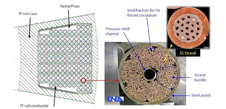
A specific aspect of the magnet system for fusion reactors is the need for mechanical structures to sustain the enormous forces ac�ng on the coils. For example, for ITER the centering force per TF coil is 403 MN and the ver�cal force on one half of a TF coil is 202 MN. The maximum ver�cal force per coil is 327 MN and 160 MN for the CS and PF magnets, respec�vely. For suppor�ng the out-of-plane forces, in the inboard region the coil straight legs are wedged along their side walls, and the curved parts are linked by six pre-compression rings. To counteract the twis�ng moment of the TF coils, due to the out-of-plane forces from the controlling poloidal field coils, the outer legs are connected by the outer intercoil structures, which form toroidal shear belts around the magnets. The overall force balance in the TF set is maintained by the TF cases, including the central cylinder formed by the wedging, the inner pre-compression rings and the outer intercoil structures. The toroidal field coil assembly rests, via 18 gravity supports, on a tokamak pedestal ring supported by a concrete crown on the floor slab of the Tokamak Building.
Magnets are permanent components and must be designed to achieve maximum reliability and a fa�gue life compa�ble with 30,000 full power tokamak pulses. Many design and manufacturing quality aspects have a bearing on magnet reliability, but experience with magnet opera�on indicates that the most common causes of magnet faults are insula�on failures. A specific feature of the ITER TF coil design is the use of thick austeni�c SS radial plates to embed the insulated conductors in machined grooves [12]. ITER is the only fusion device to date that has adopted this solu�on because of the large size, and forces, with the aim to transfer the Lorentz forces ac�ng on each conductor directly to the case. The radial plates prevent the accumula�on of forces on the conductor and its turn insula�on, reducing the probability of insula�on degrada�on due to mechanical fa�gue.
Figure 4.5 shows the fabrica�on of the radial plates that hold the conductor of the toroidal field coils. The radial plates are 8.5 m x 15 m D-shaped stainless-steel structures with grooves machined on both sides along a spiral trajectory. As shown in Fig. 4.4 each toroidal field coil is composed of seven double pancake modules which are composed of a radial plate within whose grooves the insulated conductor is embedded. Each coil contains five regular radial plates (with 12 grooves per side) and two side radial plates (with respec�vely nine and three grooves on the two sides) that were manufactured u�lising seven stainless steel forged plates made of 316 LN and but welded with local vacuum electron beam technology. Each sec�on is fully machined to the final tolerances except the welded areas.
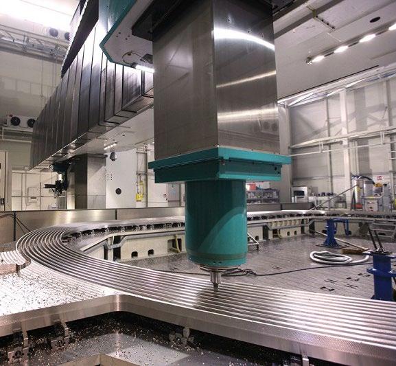
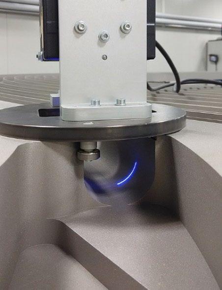
A key driver of the ITER magnet design has been the need to generate and control plasmas with a rela�vely high elonga�on k95 of about 1.7 and a rela�vely high triangularity, ���� 95 of 0.35 69. These plasma-shaping specifica�ons are more demanding than those of the 1998 ITER design 70 and
have made it necessary to adopt a design where the CS is ver�cally segmented into several electrically independent modules to provide non-uniform current distribu�ons along the ver�cal axis. The six CS modules require electrical connec�ons which can be located only in an annular gap between the TF coils and the CS. The consequences of the need for independent CS modules and the gap for connec�ons are that the CS must become a pancake-wound, free-standing coil subject to high cyclic tensile stresses.
The CS assembly includes the stack of six modules and a preload structure that compresses the CS magnet ver�cally during the assembly and the cool-down of the machine. The preload structure is made by a set of �e-plates located at the inner and outer diameters of the CS stack.
The CS conductor has a very thick square jacket which is self-suppor�ng against the radial and ver�cal magne�c loads. Sliding supports allowing radial displacements are atached to the TF coil cases to support the PF coils. The structural support of each PF magnet is guaranteed by the thick square jacket of the PF conductor
As a result of a Design Review undertaken in 2007–2008, two addi�onal sets of in-vessel coil systems were added in the ITER design baseline [59], to provide fast and reliable ver�cal instability control for the growth rates predicted for the high plasma current, high elonga�on plasma scenarios. These coils are constructed from water-cooled, steel-jacketed copper conductors.
At the �me of wri�ng, the magnets and associated feeders, are en�rely manufactured. All 19 ITER TF coils, including one spare, have been manufactured by Japan and Europe, and delivered to the ITER site. The last to be assembled Poloidal Field Coil, PF1 coil, procured by Russia, has also been delivered.
The slippage of the ITER machine assembly schedule has led the project management team to take the opportunity to build a Magnet Cold Test Bench (MCTB) on site to test some of the TF coils and the PF1 coil at their opera�onal temperature (4 K) and at full current. In addi�on to the tests to be performed, the test bench integra�on and opera�on is an opportunity to gain experience with regards to ITER upcoming commissioning and opera�on phases.
The main objec�ves of the tests are to check the high voltage ground insula�on at different temperatures, the different quench protec�on systems foreseen for opera�on and the coil performance up to nominal current (68 kA for TF and 48 kA for PF1). This will be an opportunity to test them in opera�ng condi�ons. Tests of the instrumenta�on chains and control logics foreseen for ITER opera�on will also be performed. An ITER Cold Terminal Box will be connected to the coil for the helium and electrical supplies. The cryogenic system will provide enough refrigera�on capacity with one out of the three ITER refrigera�on cold boxes and will supply supercri�cal helium to the TF winding pack, casing and busbars at 4.75 K, 0.6 MPa with a nominal mass flow of 250 g/s. One important system to be tested will be the magnet protec�on system, including demonstra�on of quench detec�on capabili�es.
In a tokamak, the vacuum vessel (VV) is a toroidal pressure-retaining vessel with a D-shaped cross sec�on providing the primary plasma vacuum condi�ons, with ports allowing access to the plasma. The VV contributes to the shielding of the surrounding coils. It is enclosed by the TF and PF coils, which, together with the intercoil structures, form a cage-like structure with interspaces used to route the VV ports. ASDEX Upgrade has a single-walled VV [ 71]. In JET the interspace of the double-walled VV is not filled with water, a neutron moderator, but is used as a secondary vacuum barrier and for gas baking [ 72]. In fusion devices with superconduc�ng magnets, however, the VV must contribute to the shielding of neutrons to limit the neutron hea�ng of the magnets operated at cryogenic temperatures.
To reduce the distance between the plasma and the TF conductor, and hence maximise the high field region accessible to the plasma, and at the same �me s�ll provide sufficient neutron shielding to the TF coils, the space occupied by the VV (and dedicated to reducing the neutron flux on the inboard side) must be minimised [ 73]. In ITER, the neutron flux must be further reduced, in par�cular on the outboard side, to avoid excessive ac�va�on of the components inside the cryostat in order to allow personnel access in excep�onal situa�ons requiring unplanned maintenance. Special aten�on had to be given to minimise radia�on streaming through major penetra�ons.
For the VV to shield neutrons efficiently, a double-wall steel structure filled with liquid cooling water ac�ng as neutron moderator, has proven to be most suitable (see Fig. 4.6). Addi�onal plates of borated steel are stacked in the interspace to reach a favourable mixture of steel and water of about 60/40% by volume [ 74].
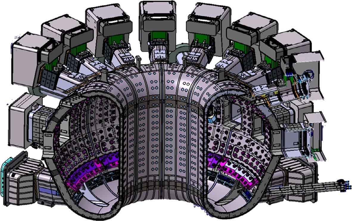
Fig. 4.6 View of four sectors of the assembled ITER VV with upper, equatorial and lower ports and in-vessel component support structures (pink) on the inner shell. Support structures below the lower ports and port plugs not shown. The splice plates used to assemble the sectors and some of the ports are highlighted in dark grey. [160].
The vacuum vessel in ITER acts as a primary safety barrier to prevent the release of radioac�vity into the environment. Because of its safety important classifica�on, a strict control of the manufacturing and inspec�ons is needed, which has shown to be complex than expected [29]
To avoid high thermal stresses due to differen�al thermal expansion, high stress interac�ons and thermal conduc�on from the VV to the cryogenic coils [ 75], the VV is supported independently of the magnets. Moreover, in nuclear devices such as ITER, the safety-classified VV (see Sec�on 6.9 in this Chapter) cannot be supported by the non-safety-classified magnet system. The VV supports the in-vessel components (IVCs) and hence the plasma-facing components, mainly the blanket/first wall (FW) and the divertor targets. The VV has stringent manufacturing and assembly requirements. Leading edges of the PFCs will be subject to very high heat loads due to charged par�cles escaping from the plasma confinement [ 76]
To avoid leading-edge overhea�ng of PFCs, it is therefore necessary to align the PFCs to the sta�c toroidal field with a precision that, for components of this size, is uncommonly �ght. The ITER FW has a prescribed alignment tolerance of around 5–10 mm [ 77] and the ITER divertor targets of around 2mm [ 78]. The customisa�on of the individual IVC support structures can compensate for misalignments in the VV inner surface to some degree [78] Nonetheless, for the successful installa�on and alignment of the PFCs, small VV tolerances are required.
To enable plasma opera�on, the currents in the PF and CS coils are varied for three different purposes: (i) to provide toroidal magne�c flux to break down the hydrogen gas into a plasma and ini�ate the discharge, (ii) to drive the plasma toroidal current, and (iii) to ac�vely control the plasma shape, radial and ver�cal posi�ons. The VV is subject to the resultant magne�c field
varia�ons as it is a toroidally con�nuous structure. To reduce its EM shielding effect during plasma breakdown, several exis�ng tokamaks, including TFTR, JET, ASDEX Upgrade or JFT-2 M, integrate bellows or electrical breaks between the VV sectors, increasing the toroidal resis�vity. Shunts can prevent arcing at the bellows and at electrical breaks between the VV sectors. But in the case of plasma ver�cal mo�on, the toroidal electrical conduc�vity of the VV causes currents to be induced that counteract the plasma movement, providing passive ver�cal stability [ 79]. Due to their flexibility, bellows between VV sectors prevent the VV ac�ng as a ring structure that would be well suited to bear ver�cal and out-of-plane loads.
Opera�onal experience with tokamaks having ver�cally elongated plasmas showed that the VV’s role in the passive stabilisa�on of ver�cal plasma mo�on was an important factor in limi�ng the loss of ver�cal posi�on control. In addi�on, VDEs associated with such loss of control produced significant forces on the VV and in-vessel structures. For example, the occurrence of VDEs required the JET VV to be reinforced [ 80]. With the increase of the plasma currents, e.g. toward ITER, the VV design approach incorpora�ng bellows or electrical breaks was abandoned. Indeed, the use of bellows was unprecedented in nuclear containment vessels and the expected difficul�es in obtaining a nuclear licence were also important considera�ons. Both shells of the ITER VV sectors are therefore fully welded at the sector field joints using splice plates [ 81]. Due to progress in opera�onal and plasma control techniques for establishing plasma breakdown, the use of a toroidally con�nuous VV is no longer considered a major issue [ 82], [ 83].
Although substan�al design and R&D efforts have been directed in the past to develop methods of manufacturing the vacuum vessel, including the realisa�on of full-scale mock ups (Chapter 7) and to refine techniques for welding and inspec�on, several cri�cal issues have emerged with the fabrica�on of the vacuum vessel sectors in ITER. The limited predic�on and control of the magnitude of the welding distor�ons, the dimensional accuracy and the achievable tolerances have led to several non-conformi�es that are now being addressed through intensive repair work. This is described in Ref. [29] and in Vol. 2.
4.6.3
Because of the long dura�on of each plasma pulse (several hundred seconds) ITER requires ac�vely cooled plasma-facing components to cover almost all the internal surface of the vacuum vessel. Designing this interface between the thermonuclear plasma and the rest of the tokamak has been arguably one of the greatest technical challenges of ITER and will con�nue to be a challenge for the development of future fusion power reactors. The interac�on between the plasma edge and the adjacent surfaces profoundly influences condi�ons in the core plasma and can damage the plasma-facing material and lead to long machine down�mes for repair.
The produc�on of neutrons in the burning plasma will also lead to deposi�on of heat and radia�on damage effects in structures rela�vely far away from the plasma e.g. the shielding blanket, the vacuum vessel, and the front ends of addi�onal hea�ng systems and diagnos�cs. Robust solu�ons
for issues of plasma power handling, plasma-wall-interac�ons, and shielding are required for the realisa�on of a commercially atrac�ve fusion reactor.
The PFCs in ITER consist primarily of two main systems: the FW as the front component of the shielding blanket, and the divertor (see Fig. 4.6), with approximate plasma-facing areas of 610 and 140 m2, respec�vely. They are both mechanically atached to the VV, divertor and the FW panels through the blanket shield blocks, and they must remove up to 850 MW of thermal power [ 84].
The main drivers for the design and technology solu�on adopted for the divertor and the first wall are the very high surface heat fluxes, the cyclic nature of the heat fluxes, and the electromagne�c loads associated with disrup�ons and ver�cal displacement events (VDEs). The typical thermal loads to which the PFCs are subjected, especially in the divertor regions, have required an unprecedented R&D and engineering effort to develop suitable high-heat flux technologies, as well as to design efficient means of heat removal. The solu�on adopted for ITER relies on the use of copper-alloys as heat sink, and water as coolant. This requires ac�ve cooling via sub-cooled pressurised water at inlet pressure and temperature of 4 MPa and 70 °C, respec�vely, and the inclusion of turbulence promoters (helicoidal tapes) or special configura�ons (hypervapotrons) in the coolant channels of the higher heat flux regions.
In the 90 s, the joining of carbon fibre composites (CFC) and tungsten to copper heat sinks largely relied on silver based brazing techniques. In a tokamak fusion environment, the silver would transmute to cadmium which is considered unacceptable in an ultra-high vacuum due to its low vapour pressure. A vigorous R&D programme was ins�gated that considered flat �le, saddle-block and monoblock armour geometries for the divertor (see Fig. 4.7 from Ref. [ 85]) and a range of brazing, diffusion bonding, HIPing and metal cas�ng techniques for joining the armour to the heat sink. Hypervapotrons were used in JET as beam stopping elements in both neutral beam injectors and in the neutral beam test bed. The monoblock type design was ini�ally developed for the CFC plasma facing material of the NET and ITER reactor designs [ 86], [ 87] and it was later adapted to tungsten armours. In this design, the armour surrounds the heat sink, yielding a par�cularly robust design, for a high number of high heat flux cycles [ 88], [ 89].
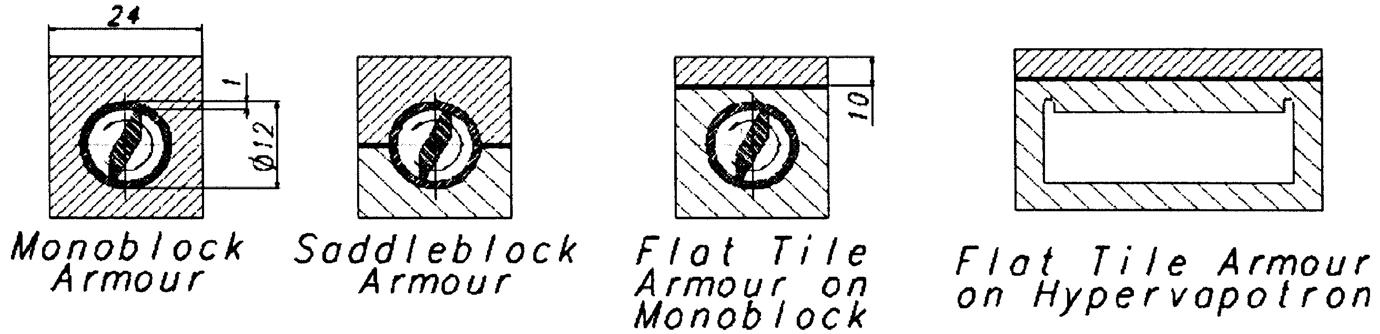
In parallel to joining development, evalua�on of the heat sink material concentrated on precipita�on hardened CuCrZr and aluminium oxide dispersion strengthened Cu alloy, DS–Cu. However, because CuCrZr has slightly beter tensile proper�es and significantly higher fracture toughness than the DS–Cu (ten �mes higher at 350 °C), it was selected as this later property is important for a component that needs to withstand large impulsive electro-magne�c loads. To offset the risks that the manufacturing thermal cycles can degrade the strength and thermal conduc�vity of CuCrZr, a number of promising joining processes were developed keeping strict control of the manufacturing cycle and maintaining the mechanical proper�es of the CuCrZr. All the most successful methods rely on using a pure Cu interlayer between armour and heat sink. For tungsten, a hot radial pressing (HRP) manufacturing technique, based on the radial diffusion bonding principle performed between the cooling tube and the armour �le, was proposed [ 90] and proved to be very successful. The bonding is achieved by pressurising the cooling tube while the joining interface is kept at the vacuum and temperature condi�ons. This technique has been used for the manufacturing of relevant mock-ups of the ITER divertor ver�cal target.
To address the most cri�cal issue of the reliability of the armour to heat sink joints, reliance was placed on tes�ng the various design solu�ons in high heat flux (HHF) test beds. A vigorous qualifica�on programme was launched involving HHF tests in a few relevant electron beam facili�es equipped with water loops, an advanced beam scanning system and relevant diagnos�cs (IR camera, X-ray detector, calorimetry). Thanks to fast two-direc�onal scanning of the narrow beam, steady-state surface heat fluxes typically up to 20 MW/m2 were generated, allowing ITER divertor relevant surface heat fluxes to be simulated for thermal fa�gue studies. These included for example: 1) ITER Divertor Test Facility (IDTF) [ 91] in the Efremov Ins�tute, near St. Petersburg, 2) the JAERI Electron Beam Irradia�on Stand (JEBIS) facility in Japan [ 92], and 3) the FE200 facility in France [ 93].
A key aspect for PFCs is the choice of plasma facing materials. For the first divertor, ITER originally considered CFCs for plasma facing materials while beryllium was, un�l recently, the primary choice for the first wall. Now tungsten will be used as armour material for both the divertor and the first wall. This topic is covered briefly below and will be discussed in more detail in Sec�on. 9.1.
The major factor that has led to the progressive reduc�on of the use of carbon in ITER has been its affinity with hydrogen and the reten�on of large amount of tri�um redeposited material (bulk reten�on also exists but is much smaller). This was very clearly confirmed by opera�onal experience in exis�ng tokamaks. In 2010, ITER decided to move to a full-W divertor. Tungsten has favourable characteris�cs for the divertor targets, which will be subject to the highest heat and par�cle fluxes: it has a high energy threshold for sputering by plasma par�cles, the highest mel�ng point of any metal, and an acceptably low affinity for hydrogen, implying a low rate of fuel reten�on. However, as noted above, it will be necessary to implement specific opera�on scenarios to avoid excessive produc�on of W and limit the concentra�on of tungsten in the plasma core.
While the first wall is typically subject to much lower heat fluxes than the divertor, it is exposed to higher energy par�cles escaping from the core plasma.
During plasma transients associated with disrup�ons, the plasma current decays with a �mescale of several tens of milliseconds. This generates eddy currents in the PFCs, which produce high electromagne�c loads by coupling to the toroidal field and generate forces which are several �mes higher than the dead weight of the components. This is an important factor affec�ng the design and material selec�on, and is one of the reasons why the first wall material has recently been changed from Be to W. The Be �les (“fingers”) were separated by thin gaps, designed to electrically isolate the �les when eddy currents occur. Tile gap bridging of beryllium-clad first wall panels induced by melt mo�on of Be at the top of the main chamber is likely to occur during an unmi�gated upward-going disrup�on current quench at high plasma current. Besides the obvious life�me implica�ons for PFCs, the occurrence of just one of such a large-scale mel�ng event has the poten�al to significantly increase the eddy currents induced by disrup�ons in the first wall panels in subsequent VDEs, even if these were well mi�gated. This would be caused by the flow of molten Be filling the gaps between first wall fingers.
This is likely to happen since the typical molten erosion thickness with Be is in the few mm scale for 15 MA unmi�gated VDEs or minor disrup�ons. This behaviour has been recently reproduced in experiments at JET. As a result, the larger eddy currents would then significantly increase the torque applied by electromagne�c forces on the FW panel fingers during follow-up disrup�ons (mi�gated or unmi�gated) with consequences for the life�me of the affected FW panels. Recent modelling suggests that during high-current downward VDEs, the Be armour can also melt. In contrast, the W armour would not melt even up to the full plasma current of 15 MA.
An addi�onal reason that has led to reconsidering the use of Be includes the fact that Be is a toxic material, adding complexity and mobility constraints on the already demanding accessibility of the welds during the first wall panel installa�on and early leak repairs. Avoiding the use of Be eliminates associated health risks, reduces the source term in case of accidents, reduces the accumula�on of tri�um in the VV, eliminates the need for an onsite Health Physics Be laboratory and related personnel, and reduces related engineering to manage confinement and controls. Finally, Be is not a relevant plasma-facing material for a fusion power plant due to its high erosion rate. Thus, the use of W for the first wall implies that it will not be necessary to replace all the panels at a later date to act as a test bed for future reactors with a fully relevant first wall material, as it would have been the case if Be had been used.
However, one of the posi�ve aspects of Be as first wall material is that it provides good vacuum condi�ons by reducing the oxygen levels through the forma�on of very stable beryllium oxides (oxygen getering). This is not provided by W and there are some opera�onal risks (e.g., increased plasma radia�on) that have to be addressed by relying on the in-situ deposi�on of boron layers by means of boronisa�on systems (more details can be found in [30].
Both the blanket/first wall [ 94] and the divertor [ 95], [ 96] are designed and manufactured according to the highest quality standards, and are suitable for replacement by RH during the opera�onal life of the ITER tokamak. Since these components operate in an ultra-high vacuum environment, they are subject to severe design, manufacturing, material and non-destruc�ve tes�ng requirements to minimise the risk of leaks. A sub-millimetric alignment between the plasma and the PFC surfaces is also required, which is challenging, since the vacuum vessel assembly is necessarily carried out under less demanding tolerances in view of its height (11.4 m) and outer diameter (19.4 m). This implies that, before installa�on, the mechanical atachments of the PFCs must be custom-machined once the survey of the full vacuum vessel has been completed and the loca�on of the plasma magne�c axis has been determined.
The shielding blanket system consists of 440 blanket modules, each module consis�ng of a FW panel atached to a shield block itself atached to the vacuum vessel. The blanket system is one of the most technically challenging components of the ITER machine, not only having to accommodate high heat fluxes from the plasma and most of the nuclear hea�ng, but also large electromagne�c loads during off-normal events and demanding interfaces with many key systems (including the vacuum vessel, blanket manifolds and in-vessel coils and diagnos�cs) and the plasma.
These have impacted the design choices, including the use of a shaped first wall to accommodate the plasma heat fluxes under different plasma scenarios, a straight inboard profile with an increased radial thickness to provide sufficient shielding for the TF coil, a shield block design with numerous cut-outs to accommodate the blanket manifold and in-vessel coil space reserva�on, with op�mised slits to maintain an acceptable load transfer to the vacuum vessel, and an atachment system providing the right support to accommodate the high EM loads while providing well characterised paths to guide halo and induced currents to the VV. In addi�on, special blanket designs are in place around hea�ng and diagnos�c ports, to allow for the discon�nuity of the ports’ entry in the vacuum vessel.
Details of design and fabrica�on of the complete blanket system can be found in Vol. 2.
Tokamaks are intrinsically ohmically heated by the toroidal plasma current, however this hea�ng mechanism is not sufficient, and addi�onal hea�ng systems relying on the injec�on of energe�c neutrals or radio frequency waves are needed [ 97], [ 98], [ 99].
One of the most studied high power hea�ng schemes is neutral beam injec�on, i.e. the injec�on of neutral hydrogen par�cles, which penetrate through the confining magne�c field, collide effec�vely with the plasma par�cles, get ionised and confined, and transfer their energy to the plasma. The penetra�on length for a beam in the plasma – before most of its power is deposited due to ionisa�on – depends essen�ally on the injec�on beam energy and plasma line integrated
density. The typical par�cle energies of present-day fusion devices are in the range between 50 keV and 130 keV mainly relying on posi�ve ion neutral beam injec�on. However, owing to its size, ITER demands a significantly higher par�cle energy of 1 MeV for its neutral beam injec�on.
Neutral beam injec�on based on posi�ve ion technology is unatrac�ve because of the low neutralisa�on efficiency for hydrogen or hydrogen isotopes at high par�cle energies. Nega�ve ions sources must be used because nega�ve ions can be very efficiently produced at the required energy. However, development of a high-power NBI at 1 MeV for use in ITER is a very complex task that requires extensive R&D, which is currently on-going. Owing to a variety of plasma resonances with high frequency electromagne�c radia�on and several absorp�on mechanisms, high frequency wave hea�ng of plasmas was always very atrac�ve. One has to dis�nguish between Radio Frequency (RF) waves (in ITER ~ 40–50 MHz, ion cyclotron frequency) and microwaves (in ITER 170 GHz, electron cyclotron frequency). Strong coupling of electromagne�c waves to the plasma par�cles can be achieved at the cyclotron resonances of ions and electrons or at a coupled resonance of both for RF plasma hea�ng by ion cyclotron resonance hea�ng (ICRH), and electron cyclotron resonance hea�ng and current drive (EC H&CD). In recent years the launching of high-power microwaves at the electron cyclotron frequency into toroidally confined plasmas has gained increased interest because of several advantageous physical proper�es: the localised EC hea�ng of the electrons, the possibility of tailoring the current profile, effec�ve current drive, suppressing MHD instabili�es and studying plasma transport by means of heat pulse propaga�on.
Addi�onally, a lower-hybrid resonance hea�ng (LHRH) system was never considered to be a day one baseline H&CD system, but a possible upgrade a�er achieving the Q=10 objec�ve, specifically to support the 5000 s Q=5 plasmas for the later phase of opera�on by method of current drive. However, important technical issues have emerged affec�ng the feasibility of the lower hybrid system and its specific applica�on to ITER plasmas. One was the failure in successfully developing 5GHz klystrons, the frequency required for ITER. The second issue was related to LH wave injec�on from the low field side of the Tokamak. Experiments in C-Mod showed that this injec�on scheme leads to parasi�c edge absorp�on at high density, absolutely not desired for ITER applica�ons. While exis�ng Tokamaks, DIII-D in par�cular, showed that this issue is avoided by high-field side injec�on, this solu�on was not prac�cally implementable in ITER due to the limited access availability to high-field side.
Around 2017, modelling efforts intensified and it was concluded that the ITER goal of a fully noninduc�ve Q=5 plasma could be achieved without LH (but increased ECH and NBI) with an expecta�on on plasma confinement (H98~1.5) for 10 MA / 5.3 T plasmas. These results led to the decision to remove the LH from the baseline in 2019.
Due to the remaining physics uncertain�es in some areas, ITER changed the hea�ng mix as risk mi�ga�on in 2024. The previous (2016) baseline envisioned a total injected power capability of 73 MW. This was provided through 20 MW of ECH (upgradable to 40 MW), 20 MW of ICH
(upgradable to 40 MW) and 33 MW of NBI (upgradable to 50 MW). The poten�al upgrades were part of the op�ons which could be decided upon during the opera�on phase, based on project needs and hea�ng system efficiency. It should be noted that these values correspond to powers injected into the vacuum vessel and are expected to couple to the plasma in the absence of plasma-related losses (e.g. inefficient ICH coupling, large NBI shine-through or par�al absorp�on of ECH). As described in Ref. [29], the increased hea�ng power levels are required to support plasma scenario development to high current with low fluence (either D or D with low T content plasmas) by supplemen�ng the absent (or low) alpha hea�ng (which requires high DT reac�vity and thus neutron flux). The higher available hea�ng power also allows for substan�al radia�ve power frac�ons in the core plasma (up to 50%) which are frequently found in present experiments with a W wall when H-mode scenarios are first developed (e.g., before op�misa�on). An overview of the specifica�ons of the ITER H&CD systems is the ITER 2024 Baseline is given in table 4.9.
Table 4.9 Specification and performance of the ITER H&CD systems
ITER design specifica�ons
Sources Objec�ves
EC 40–67 MW / CW
170 GHz
IC 10–20 MW / CW
35–65 MHz
H-NB 2(3)×16.5 MW 1 MeV, 3600 s
200 A/m2 in D
Hea�ng & Current Drive
MHD control
Plasma breakdown and start-up (3 MW)
Localised ion hea�ng
Central CD
Sawtooth control
Ion cyclotron wall
condi�oning
Hea�ng, central and offaxis CD, rota�on
Achieved (experiments and test beds)
On plasmas: 0.11 MW / 54 min
3 MW for 2 s in experiments
On test beds: 170GHz gyrotron: 1 MW, 800 s, 55% efficiency in Japan
Experimental results:
L-mode plasmas: 22 MW / 3 s, 4.3 MW / 1min, 0.38 MW / 54 min
H-mode plasmas: 16.5 MW / 3 s
1.6 GJ of IC energy (stellarator)
On test beds: >300 A/m 2 in H−, >250 A/m2 in D−.
>830 keV H-, >730 keV D−.
Ion source operated for 1 h
Experiments (one injector):
∼6.2 MW 418 keV for 1.6 s
∼6 MW, 187 keV H0 for 2 s
Concerning EC, good progress has been achieved on 1MW gyrotrons capable of very long pulse opera�on [ 100] and on ambi�ous designs which could perhaps reach both higher power and long pulses [ 101], [ 102]. There has also been progress on the design of quasi op�cal launchers [ 103], [ 104] capable of versa�le func�ons ranging from central hea�ng to NTMs instability suppression. Issues are in the domain of reliability and margins for long pulse full power opera�on of gyrotrons, as well as the control of stray radia�on arising from quasi-op�cal transmission in the launchers.
On the IC side, coupling transients due to plasma edge perturba�ons such as ELMs, pellet injec�on or sawtooth can now be mi�gated using passive circuits as demonstrated on several experiments [ 105]. However, as effec�veness of IC hea�ng in a W machine has some residual uncertain�es based on the RF generated impuri�es, it has been decided to not rely on the availability of 20 MW of power from this system for SRO. Instead, it is proposed to install an IC system of 10 MW power for SRO which provides ion cyclotron wall condi�oning (ICWC),
With regard to H-NB, powerful nega�ve ion beam systems are now used in major experiments [ 106]. In the 1990s there has been impressive progress in nega�ve ion sources and accelerators with the construc�on of mul�-megawat nega�ve-ion-based NBI systems at LHD (H0, 180 keV) and JT-60U (D0, 500 keV).
ITER, currently relies on two hea�ng beams capable each of delivering 16.5 MW for 3600 s. The accelerator is specified [ 107] at 1 MeV for 40 A of D ion corresponding to a current density of 200 A/m2. Despite considerable progress in this field, such voltages and current density have never been realised simultaneously and major R&D is s�ll required to demonstrate 1 MeV opera�on at the required ITER power level and pulse length. Recently, the specifica�ons have been reduced to around 840 keV and the use of hydrogen instead of deuterium beams. A large neutral beam test facility has been built and is opera�ng in Padua, Italy [ 108] to perform integrated developments on a prototype beam line and to check the performance and the reliability of all the key design choices.
It consists of two prototypes: SPIDER (an ITER-scale nega�ve ion source designed to achieve all ion source requirements) and MITICA (a full-size 1 MeV hea�ng neutral beam injector, capable of full accelera�on voltage and power). In addi�on, two addi�onal test facili�es at IPP Garching have been suppor�ng the development of the radio-frequency-driven ion source for ITER neutral beam injec�on for many years as part of the European roadmap: BATMAN Upgrade, a prototype ion source, and ELISE, an ion source one half the size of ITER's [ 109], [ 110].
Measurements in fusion plasmas u�lise a wide variety of diagnos�c techniques. Some methods are passive and use the detec�on of par�cles or radia�on emited spontaneously from the plasma, while other methods use ac�ve probing of the plasma with beams of par�cles or electromagne�c radia�on from an external source. Diagnos�cs based on electromagne�c radia�on are par�cularly important; fusion plasmas emit electromagne�c radia�on over a very wide spectral range, from high energy gamma rays through hard and so� X-rays, and ultra-violet, visible, infra-red through to microwave radia�on. Each wavelength range conveys informa�on about specific aspects of the plasma, and coverage of the whole range is necessary.
While the physics of the opera�on of the diagnos�cs, as established on past and present machines is, in many cases, directly applicable to ITER, the technology and engineering of the
implementa�on of the systems differ substan�ally and involve many difficult challenges. The challenges arise from several different aspects, especially the unavoidable loca�on of many of the diagnos�c components inside the vacuum vessel and in the ports where they are subject to high levels of radia�on and hea�ng. This means that many phenomena new to diagnos�c design can occur and must be considered.
The main challenges of diagnos�cs arise from opera�on aspects of ITER [ 111], [ 112] The nuclear environment sets stringent demands on the engineering of the diagnos�c systems, for example, the diagnos�c systems must meet the strict ITER requirements for the containment of tri�um and vacuum integrity; they must be able to withstand high pressures that can poten�ally occur under accident scenarios, ac�va�on must be minimised, and it must be possible to maintain and replace, with remote handling equipment, those components that are ac�vated. The combina�on of the new physical phenomena, the demanding measurement requirements, especially for long pulse opera�on, and the engineering requirements for systems installed in and suppor�ng the opera�on of a nuclear facility, lead to many challenges in diagnos�c design.
The diagnos�cs can be broadly broken up into a number of categories as shown for example in Table 4.11, magne�c, op�cal, bolometric, neutron and par�cle, spectroscopic and edge systems. The plasma control system (PCS) will u�lise measurements provided by a significant frac�on of these systems. A typical list of diagnos�cs and their purpose is shown in table 4.10.
Table 4.10. A typical list of diagnostics and their purpose
Type
Magne�c
Neutron
Parameter
- main plasma posi�on
- divertor plasma posi�on
- component (halo) currents
- error fields
- spa�al fusion power profile
- temporal and posi�onal flux
- shielding effec�veness
- reac�on rates
- cumula�ve results
- plasma energy leakage by fast ions
- confined alpha par�cle density profile
Diagnos�c
- vessel wall induc�ve sensors
- divertor magne�c coils
- Rogowski coils
- diamagne�c loops
- neutron cameras
- micro-fission chambers (invessel)
- neutron flux monitors (exvessel)
- gamma-ray spectrometer
- ac�va�on system
- lost alpha detectors
- knock-on tail neutron spectrometer
Op�cal and infrared
- electron temperature and density profiles
- electron density
- ion temperature and density profiles
Thermal Radia�on
Spectroscopy and neutral par�cles
- plasma radia�on spa�al and temporal profiles
- velocity and spa�al distribu�on of fast ions
- impurity profile (Z<5)
- integral impuri�es
- plasma rota�on, ion temperature
- ion temperature, plasma rota�on
- current density and electric field profiles
- impurity concentra�on
- ion temperature profile
- impurity spa�al profiles
Microwaves
- MHD mode detec�on
- electron density profile
- plasma posi�on control
- divertor erosion
- electron density temperature product
- plasma density profile
- ion density
Plasma Facing Components
- fast ion energy deposi�on, wall temperature
- hardware temperatures
- edge plasma density
- chamber and divertor gas analysis
- strike point detec�on
- electron density and temperature at probe
- Thomson scatering
- toroidal interferometer/polarimeter
- collec�ve scatering system
- bolometer arrays
- H-alpha spectroscopy
- visual con�nuum array
- main plasma and divertor impurity monitors
- x-ray crystal spectrometers
- charge exchange recombina�on spectroscopy
- mo�onal Stark effect
- so� x-ray array
- neutral par�cle analysers
- laser-induced flourescence
- electron cyclotron emissions
- main plasma reflectometer
- plasma posi�on reflectometer
- divertor reflectometer
- divertor electron cyclotron absorp�on
- main plasma microwave scatering
- fast wave reflectometry
- infra-red visible cameras
- thermocouples
- pressure gauges
- residual gas analysers
- infra-red thermography
- Langmuir probes
One of the main problems is the integra�on of the diagnos�cs into the tokamak, which requires a high level of coordina�on with all the other parts of the machine design process. Diagnos�cs are installed both in-vessel and ex-vessel, and the transmission systems follow paths from the vacuum vessel all the way to the diagnos�c building [ 113]. Diagnos�c system components are installed in several upper, equatorial and lower ports. Access to diagnos�c systems in the region of the tokamak area is generally quite limited and, in some cases, will be almost impossible a�er ini�al assembly. This is a key driver in the design of the systems and gives rise to a requirement for redundancy or very high reliability or both. Typically to access light from the plasma while minimising ac�va�on outside of the chamber, it is necessary to use mirrors and a labyrinth. This puts some cri�cal mirror surfaces in direct line of sight of the plasma and as a result, energe�c par�cles from the plasma can add a layer of unspecified material to the mirror surface, thus degrading the performance of the system. In some cases, a certain amount of this can be tolerated, but specific mirror cleaning techniques are being developed.
The integrity of the confinement boundaries is another cri�cal requirement in ITER. For diagnos�cs, the boundaries are typically defined by port plugs, feed-throughs, and window assemblies. For port plugs, controlling neutron leakage and minimising deflec�ons due to large electromagne�c loads is a par�cular challenge while for windows, a strong boundary is required.
Table 4.11 shows indica�ve values of neutron flux and fluence expected for different diagnos�c systems in different parts of the machine.
Table 4.11 Indicative values of neutron flux and fluence for different systems in different parts of the machine [112]. Diagnos�c
Neutron ac�va�on system head, microwave antennas
Inner vessel magne�cs, Bolometry, wiring, waveguides, microfission chambers
first wall
inner skin
3x10¹⁸
1.5 x10¹⁷
5.1x1025
2.54 x1024
Outer vessel magne�cs, steady-state sensors VV outer skin
0.77x10¹⁵ 0.009–1.3x10¹²
While radia�on effects in the magne�cs diagnos�cs and first mirror degrada�on in op�cal systems are the principal technical risks that poten�ally challenge mul�ple diagnos�cs, and hence mul�ple plasma measurements, there are other risks that have to be handled in diagnos�c design. For example, neutron hea�ng and radia�on damage in bolometers [21] magne�c field effects in microfission chambers, and spurious mode genera�on due to bends in microwave waveguides. These risks, and the avoidance and mi�ga�ng methods that are being adopted, are assessed as part of the conceptual design review process for the individual diagnos�cs concerned.
Tritium Plant
ITER is designed for opera�on with equimolar deuterium–tri�um mixtures [ 114]. The tokamak vessel will be fuelled through gas puffing and pellet injec�on, and the neutral beam hea�ng system will introduce deuterium into the machine. Employing deuterium and tri�um as fusion fuel in addi�on to genera�ng a large amount of thermonuclear power will have important consequences. Due to the small burn-up frac�on in the vacuum vessel a closed mixed deuterium–tri�um loop is required, along with all the auxiliary systems necessary for the safe handling of tri�um. The ITER inner fuel cycle systems are designed to process considerable and unprecedented deuterium–tri�um flow rates with high flexibility and reliability. High decontamina�on factors for effluent and release streams and low tri�um inventories in all systems are needed to minimise chronic and accidental emissions. A mul�ple barrier concept is needed to assure the confinement of tri�um within its respec�ve processing components; atmosphere and vent detri�a�on systems are essen�al elements in this concept.
The tri�um plant is indispensable for the opera�on of the ITER tokamak beyond the ini�al hydrogen phase, as tri�um will be produced from DD fusion reac�ons. However, the fuelling and hea�ng systems need to be fed with gases from day one of machine plasma opera�on, which requires certain parts of the tri�um plant to be available even before the deuterium phase [ 115].
Experience with the relevant technologies exists, but not at the scale and with the processing demands required by ITER, and an extensive R&D programme is underway to finalise the design of the ITER system [ 116]
A key technology and safety challenge for fusion reactors is the quan�ty of tri�um fuel in the tri�um plant (2–3 kg) and the rate at which this tri�um can be processed (maximum 200 Pa-m3/s) while at the same �me minimising tri�um release to the environment during opera�on and under accident condi�ons. The majority (~80%) of this tri�um resides in the fuel processing plant’s cryogenic isotope separa�on system (ISS) (~60%) and on the reactor’s vacuum vessel and cryopumps (20%).
ITER represents a tremendous leap in tri�um processing compared to current technologies due its higher inventory and processing flow rates [ 117], [ 118], [ 119]. The tri�um supplied per pulse in TFTR and JET was small, roughly equivalent to a frac�on of a gram per hour. In the case of ITER, the numbers are at least 3 orders of magnitude higher.
The main func�ons of the tri�um systems of ITER can be summarised as follows:
• handling of incoming and outgoing tri�um shipments;
• storage of tri�um and deuterium, and transfers to and from the fuel cycle;
• management of airborne contaminants;
• extrac�on of decay 3He;
• delivery of deuterium, tri�um and mixtures for fuelling, supply of divertor impurity seeding gases and measurement and determina�on of tri�um inventories;
• torus vacuum pumping and transfer of gases to tri�um processing systems;
• processing of tokamak exhaust gas, of tri�ated gas streams generated during tri�um recovery from plasma-facing components, and of other tri�ated off-gases for recycling of tri�um and deuterium along with separa�on of hydrogen into specific isotopic species for refuelling at specified flow rates and isotopic composi�ons;
• detri�a�on of water and recovery of the tri�um;
• extrac�on of tri�um from test blanket modules (TBMs) and tri�um recovery;
• atmosphere detri�a�on during normal, maintenance and accidental condi�ons and decontamina�on of gases prior to controlled release into the environment.
Considering the list of func�onal requirements, the complexity of the ITER fuel cycle systems, and taking the criteria for safe handling of tri�um into account, it becomes obvious that design integra�on of the ITER tri�um plant systems will be one of the major tasks during design and construc�on.
The tri�um plant, essen�ally a nuclear gas processing plant, receives deuterium–tri�um (DT) gases from the torus and neutral beam vacuum systems, removes impuri�es, separates isotopes, and delivers D2, DT and T2 to the tokamak fuelling systems. The tri�um plant also includes equipment for detri�a�ng gases and water. Because only a small frac�on of the injected fuel is burned on any given pass through the plasma, the exhaust contains a mixture of all the hydrogen isotopes (H, D, T) fed into the plasma. In general, this mixture must be isotopically separated to: 1) remove pro�um (H) that enters the plasma exhaust from outgassing or leaks; and 2) separate the D and T into products suitable for reinjec�on. In general, the tri�um inventory in the isotope separa�on system (ISS) will increase with the amount of tri�um separa�on required, which in turn increases with tri�um throughput and with the degree of tri�um enrichment.
An important size driver of the ISS is quan�ty of pro�um present in the plasma exhaust. The ITER ISS is designed for complete processing of the plasma exhaust due to the intermitent opera�ng schedule which is likely, especially in the early phases of opera�on and which would tend to elevate background levels of pro�um. If the pro�um outgassing rate decreases in future power reactors (e.g. due to fewer maintenance openings), then con�nuous processing of the full plasma exhaust stream may not be necessary. Instead, only some side stream would need to be processed, and the ISS could be reduced in size and tri�um inventory. ITER will be a good test of the amount of pro�um to be expected because of its reactor-relevant size and much higher opera�ng capacity than previous fusion machines.
Experiments carried out on ITER will clarify the usefulness of isotopically enriched fuel (as dis�nct from 50:50 DT mixed fuel) and may result in a reduc�on of the ISS requirements for a reactor. Going from ITER to power reactors, another important difference is the higher-than-average tri�um throughput due to the expected near-con�nuous plasma opera�on. However, ITER has been designed to handle the plasma exhaust on a steady-state basis. In principle, the separa�on duty for ITER could have been reduced by sizing the ISS for the �me-averaged flow. This approach does not necessarily reduce overall system-wide tri�um inventory, but keeps the amount in the ISS itself lower, in line with the goal of segrega�ng tri�um inventory. This is not possible with a power reactor.
For the separa�on process itself, in the throughput range relevant for ITER and power reactors, the most effec�ve process for isotope separa�on of hydrogen isotopes is cryogenic dis�lla�on. The only real disadvantage of dis�lla�on is that a large frac�on of the hydrogen (and T) is in liquid form, and the process therefore has rela�vely large inventories. Gas phase con�nuous membrane columns have been proposed for the pro�um stripping sec�on of the isotope separa�on system [ 120]. This process offers poten�al for inventory reduc�on and greater stability of opera�on under fluctua�ng feed condi�ons, but further development is necessary to adapt the process to higher feed rates, and a large pumping system is needed. Recent advances (1980s and 1990s) in hydrogen dis�lla�on [ 121] have resulted in designs that are much more compact with lower inventories than in the past. In large part, this has been through careful understanding of the process and the packings, so that the systems can be op�mised to run at lower inventories than were previously prac�cal. The design tools that have supported this improvement are welladvanced, but there are s�ll areas of experimental research where further improvements may be possible.
Fuelling and shattered pellet injection for disruption mitigation
The ITER fuelling system mainly consists of the pellet injec�on system (PIS), gas injec�on system (GIS) and disrup�on mi�ga�on system (DMS).
Pellet injec�on from the inner wall is planned for use in ITER as the primary core fuelling system since gas fuelling is expected to be highly inefficient in fuelling the centre of burning plasmas. Tests of the inner wall guide tube have shown that 5 mm pellets with speeds up to 300 m/s can survive intact and provide the necessary core fuelling rate. Modelling and extrapola�on of the inner wall pellet injec�on experiments from the present day’s smaller tokamaks leads to the predic�on that this method will provide efficient core fuelling beyond the pedestal region. Using pellets for triggering frequent small edge localised modes is an atrac�ve addi�onal benefit that the pellet injec�on system can provide. A descrip�on of the ITER pellet injec�on system’s capabili�es for fuelling and ELM triggering, and performance expecta�ons and fusion power control aspects, are discussed in Volume 2.
Shoo�ng pellets down a precise path is another challenge. Because the tubes that direct the pellets into the tokamak will be unusually narrow at ITER, the flying pellets can deviate no more than one degree from an arrow-straight path. The bigger ITER pellets will require more force to send them into the tokamak. Applying that force too fast, however, will break the pellet. Another engineering challenge awaits at the other end of the flight path. By design, the pellets slam into a curved sec�on of the tube wall at 250 m/s, breaking into pieces. Those fragments will disperse across the plasma, cooling it down as the plasma expends energy stripping electrons off the cold atoms. The ORNL team is now inves�ga�ng how pellet speed, pellet material and tube angle affect the all-important fragment distribu�on.
First-of-a-kind achievements have already emerged from the US ITER and ORNL team, including the largest cryogenic frozen hydrogen pellet ever formed and fired by a pellet injector "gun" (25 mm in diameter) and a novel three-barrel pellet injector for delivering the pellets to the plasma. The pellet guns use a gas propellant to fire pellets at 300 m/s or about 1080 km/h.
The ITER vacuum pumping system is a first-of-a-kind in size and complexity, comprising (in addi�on to the major cryopumps) at least 300 mechanical pumps, as well as 10km of vacuum lines. Ordersof-magnitude improvements in vacuum reliability are required compared to exis�ng and past fusion devices [ 122].
The vacuum systems for ITER are characterised by the requirements for tri�um compa�bility, tolerance of high magne�c and radia�on fields and remote maintainability. In addi�on, although the vacuum levels are rela�vely modest, high pumping speeds are needed to achieve the high gas throughputs required. While the ITER torus base pressures are like JET, the ITER pumping du�es are significantly more demanding because the torus volume is approximately 10 �mes larger and ITER plasma shots will be up to 300–500 s (short pulse opera�on) and up to 3000 s in long pulse mode, compared with a few seconds for JET. The tri�um throughput during the main DT campaign (DTE) in 1997 in JET was roughly equivalent to one day of planned ITER DT opera�on.
The main pumping systems are the six torus exhaust pumps, the four cryopumps for the neutral beam injec�on systems used in plasma hea�ng, and the two cryopumps for the ITER cryostat to maintain the low pressure required for the opera�on of the superconduc�ng magnets. In addi�on, there is a mixture of standard and custom pumps in the roughing pump system (RPS), diagnos�c, transmission line, and service vacuum system (SVS). The complex pumps have been tailored for the very specific applica�ons and requirements at ITER. All are based on cryopanels, cooled with supercri�cal helium and coated with ac�vated charcoal as sorbent material. Research and development have shown that charcoal from finely ground coconut shells has the right density and porosity for imprisoning the helium par�cles in ITER. The outgassing rates from plasma-facing components and the gas species evolved are strongly dependent on the selec�on of plasma-facing materials.
It is uncertain if cryopumps will prove to be an effec�ve VV pumping op�on for a steady-state fusion reactor like DEMO. This uncertainty relates to possible reliability concerns for cryopumps given their transient mode of opera�on, i.e. cycled fuel loading and unloading modes. A solu�on called the “direct internal recycling” (DIR) approach has been proposed that has the poten�al for reducing the DEMO tri�um processing plant size to that of ITER’s, or 75% smaller [ 123]. A key technology proposed for the DIR approach is called a “superpermeable” metal foil pump (MFP) [ 124], [ 125], [ 126] The MFP is a steady state, high temperature vacuum pump that works by directly extrac�ng the unburnt hydrogen fuels from the plasma exhaust, instead of condensing them. Because this extracted fuel is free from plasma exhaust impuri�es, it can be sent directly to the reactor’s fuelling system for reinjec�on into the plasma instead of to the fuel processing plant.
The main experience of remote handling in fusion facili�es comes from the JET device. JET has rou�nely used teleoperated robots, controlled by human operators from the safety of a control room. The remote maintenance system in JET [ 127], [ 128] has been the most developed and comprehensive of its type, having accumulated over 30,000 hours in opera�on [ 129]. It used two snake-like booms to enter the vacuum vessel which moved around the vessel controlled remotely by operators, carrying other subsystems and payloads such as the MASCOT tele-manipulator. The booms were reconfigurable to adapt to a wide range of missions. A similar deployment principle is used for the Ar�culated Inspec�on Arm, used in the EAST and WEST devices [ 130]. Although limited to 10kg payloads, it can operate under vacuum condi�ons.
The ITER remote handing system involves a significant extrapola�on from JET experience [ 131]. For instance, the dose rate inside of JET has typically been a few mGy/h, compared with that an�cipated in ITER of several hundred Gy/h , a factor of about two orders of magnitude higher. A dedicated hot cell with specialised remote equipment is required to process components leaving the reactor [ 132]. In future systems it is expected that an en�re ac�ve maintenance facility will be required to process the highly ac�vated components, with many large areas being out of bounds for human access [ 133]. This expanding boundary implies that the number of maintenance ac�vi�es that must be performed remotely will increase drama�cally. Similarly, with respect to the weight of components requiring remote maintenance, the JET system manipulated weights of about 50 kg, compared to several tens of tonnes expected in ITER, two orders of magnitude higher. These differences have required the iden�fica�on and development of new RH approaches and RH tooling solu�ons.
In-vessel maintenance of ITER also involves the regular occasionalof plasma-facing components with cooling interfaces, and therefore requires the cu�ng and joining, of cooling pipes [ 134], [ 135]. Most of these pipe joints are at loca�ons under high radioac�vity but low accessibility and visibility. No direct human interven�on is possible inside the vacuum vessel and other peripheral areas of the reactor [ 136]. In addi�on, joints are subjected to elevated temperature and cyclic
thermal loads, and leak �ghtness is key to protec�ng the tokamak vacuum during opera�on [ 137]. Therefore, specifically developed tools with safe and reliable remote maintainability are required to be deployed through entry ports and carry out maintenance tasks in space-constrained environments.
Pipe maintenance related topics is a cri�cal area of R&D and there are many technical challenges and unresolved issues. Relevant tooling and systems for such processes have also been under development and a review of pipe cu�ng, welding, and NDE technologies for use in fusion device is provided in Ref. [ 138].
Numerous cu�ng and re-welding jobs on the primary circuits of a nuclear power plant (NPP) have been undertaken over the years. However, they are primarily one-off repairs which were not necessarily foreseen when the plant was designed. Examples of this are nozzle replacements or repair to weld-roots which are found to be corroded during rou�ne inspec�ons. In the case of ITER however, for unavoidable reasons, several tens of in-vessel primary cooling circuit cu�ng and re-welding opera�ons might have to be carried out to maintain its basic opera�on in case of correc�ve maintenance
For the divertor alone there are 108 cooling pipes to cut, re-weld and inspect for every divertor exchange - so this ac�vity could be carried many more �mes compared to a few �mes in the life of an NPP. For the blanket there are 400+ connec�ons to make under fully remote condi�ons even during first installa�on
The RH System of ITER is described in detail in Vol. 2 and it involves several systems:
• blanket RH system used to replace individual first wall panels and blanket shield blocks.
• divertor RH system used for the replacement of divertor cassetes. Cassetes are retrieved by an ini�al toroidal transla�on, sliding on toroidal rails, and are then withdrawn from the vacuum vessel in the radial direc�on via three lower ports;
• cask and plug RH system; large transfer casks carry the strongly ac�vated and contaminated in-vessel components from the tokamak complex to the hot cell complex (HCC). These casks provide confinement (for dust and tri�um), but not radia�on shielding. Consequently, they are fully robo�c, typically transferring equipment through the tokamak complex and HCC at night, which necessitates the evacua�on of personnel from these facili�es during the transfer
• NBI RH system used to maintain neutral beam components in the neutral beam cell.
In ITER, remote opera�ons, maintenance equipment, and reactor components have been designed all together, as all associated constraints must be considered in an integrated way to achieve a successful design sa�sfying the life�me opera�onal requirements [ 139]. As a result, the verifica�on and valida�on of RH solu�ons, which requires physical mock-up tes�ng, have been done since the early phase of the design (see Sec�on 7.3) to show that they work as intended in
a representa�ve setup. The ITER Divertor Test Pla�orm 2 facility provides an example in this regard. This has allowed extensive tes�ng to ensure that the design concept for the divertor RH system is feasible [ 140], given that it must be able to operate in a highly constrained space and in the presence of gamma radia�on.
The RH approach implemented in ITER together with the detailed descrip�on of the RH systems and tools is detailed in Vol. 2. As an example, the reference design of the divertor RH system [ 141] (see Fig. 4.8) consists of two movers. The Cassete Mul�func�onal Mover transports the 10 t divertor cassetes radially to and from the vessel through the maintenance port. Several interfacing end-effectors also allow it to transport a range of other hardware and RH equipment.
The Cassete Toroidal Mover locates the cassetes inside the vessel, moving them along toroidal rails. A variety of tools are used to cut cooling pipes, lock the cassetes in place, and collect contaminated dust from the work area. These tools are deployed with a dexterous, teleoperated manipulator arm, mounted on the movers.
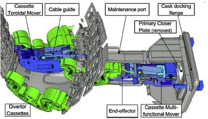
For the maintenance of the blanket first wall and shield blocks (up to about 1m x 1.4m x 0.5m, 4.5t in the later case), ITER is considering the use of an In-Vessel Transporter (IVT), which is composed of a manipulator mounted on a monorail-type vehicle and an ar�culated rail [ 142], [ 143]. During the EDA, the JAEA fabricated a prototype of the IVT system [ 144] (see Chapter 7) and confirmed its feasibility including reduc�on method of vibra�on induced by blanket load [ 145], automa�c posi�oning of the blanket [ 146] and rail deployment procedure of the ar�culated rail [ 147]. However, some risks remain, and R&D is s�ll in progress to confirm the feasibility.
In the 2016 baseline, the principal device for installing blanket shield blocks and first wall panels was the in-vessel tower crane (IVTC). During the development of the 2024 baseline, several studies were conducted to iden�fy ways to speed up the in-vessel installa�on processes and have more overlap or parallelisa�on of the installa�on of the different in-vessel components. One of the possibili�es iden�fied was to parallelise the installa�on of the blanket and divertor systems.
However, since the IVTC operates on rails installed in the lower part of the vacuum vessel (normally occupied by the divertor), it cannot be used when the divertor cassetes are installed, so it was clear that an addi�onal tool would be needed to allow the installa�on of the blanket and divertor to proceed in parallel. Hence, it was decided to proceed with the design and procurement of two blanket assembly transporters (BATs) which can be deployed and operated fully independently from the IVTC. BATs are long-reach, serial robo�c devices deployed in a can�levered fashion from equatorial ports (with no need to rely on the rails in lower part of the vacuum vessel). During the pre-SRO assembly phase, they will be used to install a certain number of lighter shield blocks (<3 t) and the temporary first wall panels. BATs are configured to deploy specific end-effectors (e.g., for bol�ng and torquing), and for the welding of hydraulic connectors (should the opportunity to proceed with this scope during the first assembly phase be taken). These end- effectors will be provided by Japan.
Fusion reactors following ITER will face further challenges, related to the addi�onal requirements as designs approach commercial deployment. Higher fusion power will lead to increased ac�va�on and to higher radia�on levels during maintenance, which will be sufficient to damage electronic systems that are not properly shielded. Deployment of robo�c systems inside the vessel, while s�ll possible for ITER, will be unfeasible for a DEMOnstra�on Fusion Power Plant (DEMO) and future power plants unless adequate radia�on-resistant technology is developed [ 148]. Another key challenge for future fusion reactors is their larger size, which means very large components need to be handled with high precision. For instance, the largest components in EU DEMO could be 10 m tall, have masses in the order of several tens of tonnes, and require a posi�oning accuracy in the order of 20 mm [ 149].
Inside fusion power plants, a number of maintenance tasks will have to be performed remotely. This, in combina�on with the increasing size and mass of reactor components and the need to achieve commercially relevant plant availability, would mean that future remote maintenance systems will need to be faster, more capable and more automated. Future fusion plants will then need to evolve highly integrated designs where the maintenance strategy is considered from the outset and built into the very architecture of the plant. The handling strategy for such large components is a fundamental driver for the architecture of the en�re plant.
To reach commercially relevant levels of plant availability, the speed of maintenance systems and the ability to perform tasks in parallel must improve significantly. It will be necessary to automate many maintenance ac�vi�es, leveraging the produc�vity improvements already demonstrated in manufacturing industries worldwide. However, deployment of automated and autonomous systems with reduced human supervision in such harsh environments is a significant technology challenge, par�cularly considering the need for acceptance by regulators.
Since the very beginning, one of the key ITER objec�ves was to test reactor-relevant blanket modules and associated subsystems up to a given neutron fluence to demonstrate the capability to reach tri�um self-sufficiency and also to produce and extract high grade heat for electricity genera�on in a reactor.
Prior to the start of the ITER CDA, there was a debate as to whether to consider reactor-relevant technology developments for DEMO separately from physics research. This was advocated in 1985 and later [ 150], [ 151]. Specifically, plasma-based Volumetric Neutron Source (VNS) designs based on mirrors, reversed field pinches and tokamaks were iden�fied and proposed to address the fusion nuclear technology R&D aspects [ 152]. These device concepts were small with major radius of about 2–3 meters, low power (<100 MW), low tri�um consump�on, and with designs emphasising maximum access to the fusion core.
The decision was taken not to have a major dedicated technology tes�ng facility in Europe and other regions, but to use ITER for both physics and technology developments, including extensive nuclear component tes�ng relevant to a future fusion reactor. A problem with this approach is that physics tes�ng requires rela�vely large fusion power (e.g., 300–600 MW in ITER) to have performing plasmas, whereas nuclear technology tes�ng only requires low fusion power (~ 20–50 MW) but needs high n-fluence (>10 dpa) [ 153]. The combina�on of high power for physics tes�ng and high fluence for nuclear technology tes�ng in a single device leads to high tri�um consump�on (for example >110 kg per full power year in DEMO). Such large amounts of tri�um can only be provided if the device has its own self-sufficient tri�um breeding blanket that operates reliably from the very beginning of opera�on.
ITER opera�on relies on u�lising available external supplies of tri�um that are very limited [ 154]. Consequently, achieving tri�um self-sufficiency in the so-called breeding blanket will be an unescapable requirement for any next-step fusion nuclear facility beyond ITER. Developing a breeding blanket that meets the required performance and reliability goals is essen�al for the deployment of future fusion reactors.
Breeding blanket systems have been under development since the start of civil fusion inves�ga�on in the early 1950s [ 155]. Many concepts were inves�gated, ranging from more conserva�ve concepts to advanced and riskier concepts for future reactors. The major candidate breeding materials consist of lithium-based liquid breeders, mainly liquid metals, and lithium ceramic breeders. The degree of conserva�sm in the concept is o�en linked with the choice of structural material since more advanced concepts generally require opera�on at high temperatures to provide for high cycle efficiency and power produc�on performance and, thus, a greater degree of extrapola�on in structural material proper�es and technology. The choice of structural material, in turn, influences the choice of breeding material based on the accommoda�on of key issues such as material compa�bility and temperature limits.
Self-sufficiency in tri�um produc�on was never an objec�ve of ITER nor its precursors (INTOR/ NET). In this respect, mock-ups of breeding blanket elements, either in the form of module or poloidal segment tests were considered adequate to allow reliable extrapola�ons. However, ini�ally a tri�um breeding blanket was introduced in the INTOR and NET basic machine designs in order to reduce the demands on tri�um supply and thus the opera�ng cost. For this breeding blanket, the goal of full reactor relevance was replaced by the condi�on not to interfere with the reliable opera�on of the basic machine. To achieve this objec�ve and to maximise the shielding capability on the inboard of the torus, the breeding blanket was restricted to the outboard and upper sec�ons of the plasma chamber, covering about 50–60%, of the available space.
In the case of NET, the adopted blanket maintenance approach (i.e. removal of the banana-like segments through the upper vessel ports) required a strong full steel structure in the inboard segments to increase the s�ffness of the segments during removal thus avoiding a dangerous flexibility and oscilla�ons. In the early design phase, in 1995 ITER followed the same strategy by crea�ng the TBM Program where several concepts of breeding blanket were proposed for installa�on in a second phase of opera�on aiming at extensive nuclear tes�ng to achieve the produc�on of a significant amount of tri�um and significant levels of accumulated n-fluence.
For the ini�al phase of opera�on (Basic Performance Phase (BPP)), focused primarily on achieving sa�sfactory plasma physics performance, a shielding blanket was considered for the inner coverage of the machine. During this phase, par�al tes�ng and qualifica�on of breeding blanket modules and associated subsystems (e.g., high-temperature, high-pressure coolant system, tri�um extrac�on system) to be deployed in equatorial ports was considered. The blanket shield system was designed to offer the possibility of replacing the shield by a breeding blanket within the same dimensional, maintenance, and coolant constraints, to provide the tri�um to meet the technical objec�ves of the more technology oriented nuclear technology phase (Enhanced Performance Phase (EPP)). Provisions were also made to install and test more reactor-relevant tri�um breeding blanket in specially designated equatorial ports.
However, a�er thorough technical assessments the strategy to replace the shielding blanket with a breeding blanket was found to be unfeasible or at least very risky. For example, a specific problem was related to the choice of the coolant condi�ons, that in the case of ITER, was water at rela�vely low temperature and low pressure. Tri�um release and recovery from the breeding blankets is a cri�cal issue that is very much temperature dependent. This is par�cularly the case for ceramic breeders in which tri�um transport is strongly dependent on the temperature of opera�on of the breeder and for which, below a certain temperature threshold, tri�um release would be inhibited resul�ng in very high tri�um inventory levels.
Installing and opera�ng a breeding blanket cooled with low-temperature water would make the process of tri�um release very slow and the goal of maintaining acceptable tri�um inventory levels very challenging.
Special design provisions, relying on thermal barriers to maintain the breeder region at sufficiently high temperature levels were not considered to be sufficiently reliable. Calcula�ons for ITER show that the blanket, its primary/intermediate cooling circuit and tri�um recovery system requirements added significantly to plant unavailability. Replacing these items with a breeding blanket would reduce machine availability. Also, the choice of a low temperature low pressure driver blanket for ITER with the aim to provide reliable and safe opera�on while maximising tri�um breeding would not be reactor relevant. Performance results on such a blanket could not be extrapolated to DEMO which would u�lise a high temperature blanket. However, the use of a high temperature blanket on ITER was also not a viable alterna�ve, since it would introduce more complexity and risk, as it would be more likely to fail and be poten�ally more damaging when it fails, thereby significantly impac�ng the availability of the whole machine. Also, the level of maturity of such blanket concepts was very low and their development and valida�on would be riskier and require substan�al �me and resources.
These considera�ons led to a substan�al curtailing of the nuclear mission of ITER and the implementa�on of a strategy that relies on u�lising a shielding blanket in ITER and tes�ng breeding blanket modules and associated subsystems (so-called Test Blanket System or TBS) in equatorial ports (i.e., the TBM Program men�oned above). Even more so, when the wall loading and neutron fluence objec�ves of ITER were reduced for the final design. Extrapola�on to DEMO component condi�ons for materials irradia�on data now relies on dedicated materials irradia�on facili�es, such as IFMIF/DONES 156 in Europe. Chapter 10 in this volume, whilst some of the op�ons being considered for minimising the risks remaining with the performance and the reliability of the breeding blanket that represents undoubtedly one of the largest gaps to be filled beyond ITER can be found in volume 2. The design work for ITER's test blanket modules and associated subsystems is being conducted in the Par�es, according to boundary condi�ons established by the ITER project.
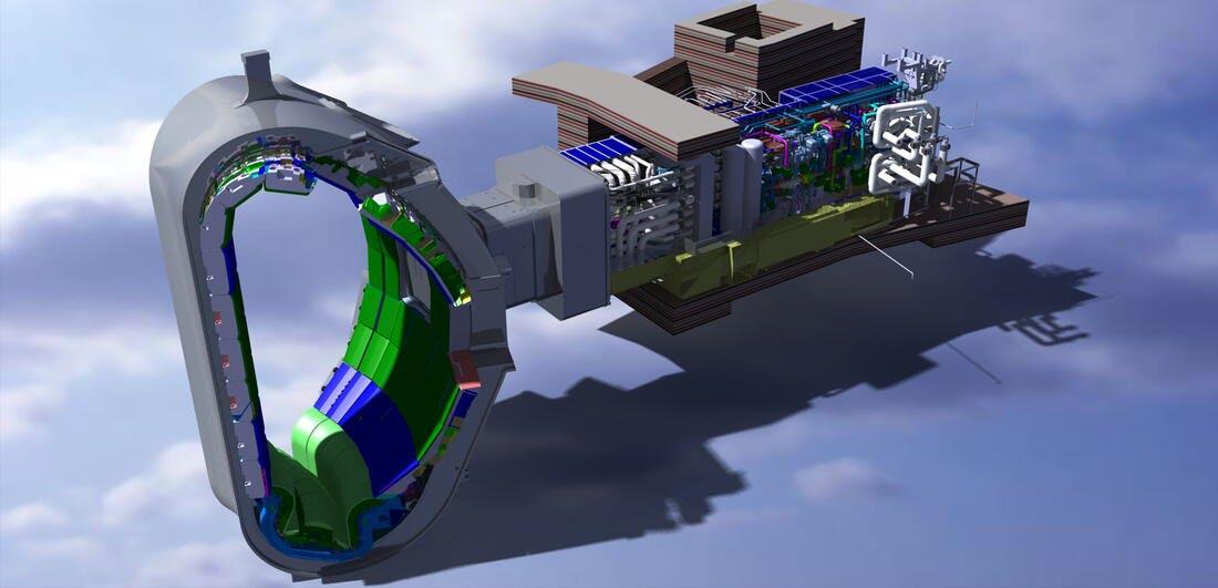
[161].
Tri�um breeding blanket tes�ng s�ll represents a cri�cal element of the ITER mission, as much can be learnt despite the reduced performance. The ITER TBM Program represents the principal strategy by which ITER will provide the first experimental data on the poten�al of fusion as an energy source. TBS tests in ITER will provide essen�al informa�on toward resolving this challenge. The major tes�ng objec�ves are:
1. valida�on of theore�cal predic�ons of structural integrity and response under combined relevant thermal, mechanical and electromagne�c loads;
2. valida�on of tri�um breeding predic�ons;
3. valida�on of tri�um recovery process efficiency and tri�um inventories in blanket materials;
4. valida�on of thermal predic�ons for heterogeneous breeding blanket concepts with spa�ally dependent volumetric heat sources;
5. demonstra�on and understanding of the integral performance of the blanket systems.
Un�l recently, many ITER Par�es viewed the TBS tes�ng in ITER as their only component-level tes�ng step before a DEMO reactor, deferring the materials tes�ng to DEMO. New ideas are now emerging and are described in Chapter 10. Originally three equatorial ports were allocated to test six different types of TBMs. In November 2018, the ITER Council endorsed the proposal of an op�misa�on of the TBSs configura�on based on the use of only two equatorial ports. Such an op�misa�on required the reduc�on of the number of simultaneously opera�ng TBSs to a maximum of four, of which the in-vessel part, the TBMs, is fited into the two ports, two TBMs per port.
All ITER Members contribute to the TBM Program, and a tes�ng strategy has been developed for approximately the first 10 years of ITER opera�on. Tests will be carried out on mock-ups not only of the tri�um breeding blankets themselves, but of complete systems (the TBSs), each of which consists of a TBM together with several subsystems providing coolant to the TBM, a dedicated tri�um extrac�on system, a coolant purifica�on system, a tri�um accountancy system and associated instrumenta�on and control (I&C) systems. All the four TBSs are independently controlled and operated from the centralised ITER Control Room. A schema�c view of a TBS and its loca�ons in the ITER Tokamak Complex can be seen in Fig. 4.10 that shows the example of the helium-cooled ceramic breeder TBS.
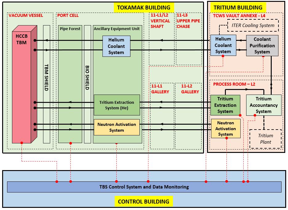
Fig. 4.10 Schematic view of a TBS and its locations in the ITER Tokamak Complex (example of the helium-cooled ceramic breeder TBS) [166]
The TBSs’ func�onal characteris�cs are dictated by the opera�onal condi�ons and requirements expected in DEMO and, in this sense, they differ from other major ITER components that are designed specifically in compliance with requirements derived from ITER’s target performance. However, the TBSs must be fully integrated into the ITER facility and therefore they must be compa�ble with the systems and opera�onal procedures of ITER, as well as with the ITER opera�ng plan. Moreover, it is required that opera�on of the TBSs should not impact ITER’s opera�onal performance, safety, and availability. More details on the ITER TBM Program can be found elsewhere (see for example [ 157], [ 158] and in volume 2.
The main characteris�c of the four TBMs to be tested in ITER based on informa�on available today are shown in Table 4.11. The four TBMs are planned to be installed before the beginning of the DT-1 opera�on phase and it is assumed that they will be operated throughout. TBSs opera�ons are expected to be con�nued during the DT-2 opera�on phase either for the same TBSs or for more advanced TBSs.
Table 4.11 Main characteristics of the four TBMs
Water cooled TBMs
Water-cooled lithium lead (WCLL) developed and procured by Europe
TBM structure made by EUROFER97 steel, Pb16Li (mul�plier/ breeder), 90% 6Li enrichment
Coolant: H2O at 15.5 MPa, 295/328 °C inlet/ outlet temperatures
T-purge gas: Helium +0.1 H2 at 0.4 MPa
Water-cooled ceramic breeder (WCCB) developed and procured by Japan
TBM structure made by F82H steel, Be pebbles (mul�plier), Li2TiO3 pebbles (breeder) 60% 6Li enrichment
Coolant: H2O at 15.5 Pa, 280/325 °C inlet/ outlet temperatures
T- purge gas: Helium <0.1 H2 at 0.4 MPa
Helium cooled TBMs
Helium-cooled ceramic pebble (HCCP), jointly developed and procured by Korea and Europe
TBM structure made by EUROFER97 steel, Be pebble (mul�plier), Li4SiO4 or Li2TiO3 pebbles (breeder) 30-60% 6Li enrichment
Coolant: He at 8 MPa, 300/500 °C inlet/outlet temperatures
T- purge gas: Helium +0.1 H2 at 0.3 MPa
Helium-cooled ceramic breeder (HCCB), developed and procured by China
TBM structure made by CLF-1 or CLAM steel, Be pebbles (mul�plier), Li4SiO4 pebbles (breeder) 90% 6Li enrichment
Coolant: He at 8 MPa, 300/500 °C inlet/ outlet temperatures
T- purge gas: Helium +0.1 H2 at 0.3 MPa
The en�rely novel aspect of the TBM Program at ITER is underlined by that fact that a complete TBS with all the ancillary sub-systems has never been operated, not even at laboratory scale. A for�ori, the ITER tes�ng program for the TBS will be the first �me that a TBS will have been operated in the tokamak environment. Therefore, most of the TBS components must be considered as technological innova�on and, as such, they require demonstra�on and valida�on. The tes�ng of TBSs in ITER is viewed as an essen�al step to reduce the technical risks and uncertain�es associated with the demonstra�on of power extrac�on, tri�um breeding technologies and tri�um management essen�al for a DEMO fusion power plant. Large modelling development ac�vi�es are also part of the TBM Program for achieving reliable data extrapola�on to DEMO breeding blankets. The licensing, opera�on, and maintenance of the TBSs are deemed to be valuable in providing informa�on and support for licensing a blanket that breeds tri�um However, the TBMs will operate only up to low n-fluence (< 1dpa) and mainly at low duty factors
(with the excep�on of some dedicated days). Thus, large gaps will remain even with a successfully completed TBM Program. Risk mi�ga�on strategies to accelerate the deployment of fusion power, relying on the availability of qualified breeding blanket systems, are being discussed between the ITER members and are described in Chapter 10.
A power-producing tokamak reactor, like ITER, is a highly complex device embodying the results of innumerable assump�ons and decisions. The ITER design process has clearly shown that one cannot chose parameters in isola�on. The plasma design condi�ons affect the engineering design, and vice versa. Even among the engineering design condi�ons themselves, a constraint arising from a system can affect another system. For example, even if high field superconductors could be applied to increase the fusion power density and reduce the plasma size, the dimensions of the core structure might not become smaller because of the increase of the coil structure size to overcome the higher forces and stresses that roughly scales like B2. In addi�on, even if a high field and high current density superconductor could be applied, the plasma-facing components could not handle the resultant high wall load condi�ons, unless new high heat flux materials are developed. Therefore, there exists some op�mum magne�c field sa�sfying these combined condi�ons for known reliable technologies.
The design of ITER (and in general of any other fusion reactor) was affected by a high degree of complexity/system interdependencies and mul�ple design drivers across various systems that impacted the design and performance. There were several design choices that had to be made and pervasively affected the overall design layout and the performance of the nuclear fusion plant and its maintainability and safety, because of the interfaces with all key nuclear systems. These challenges had to be addressed by the scien�sts and engineers responsible for designing and developing robust and reliable solu�ons, enabling safe machine opera�on. Such an integrated approach is essen�al to the successful development of the knowledge base for atrac�ve fusion energy sources because of the complex nature of fusion systems and the mul�-disciplinary aspects of the underlying science and engineering. This approach includes the iden�fica�on and the subsequent evalua�on and impar�al assessment of mul�ple design op�ons through parallel inves�ga�ons for systems and/or technologies with high technical risk or novelty.
For example, robust structural concepts were needed to enable the set of TF coils (18 in ITER) to withstand the centring and ver�cal forces. Several concepts have been inves�gated in the past including full wedging, or par�al wedging, and bucking against a CS or bucking post. However, all concepts relying on bucking are very complicated in prac�ce, as they require the TF coil to slide against the bucking cylinder or the CS coil to accommodate mo�on during opera�on. Very complex structural designs are needed to support out-of-plane loads on the TF coils without transferring this twist to the CS. For the bucked and wedged configura�on, detailed analyses showed that the stress on the TF leg is extremely sensi�ve to the assembly tolerance between TF
coils and CS (or whatever bearing surface is placed in between). Sub-millimetre tolerances are to be achieved over the large contact surface for the stress distribu�on to be predictable, which is imprac�cal. A�er in-depth assessments conducted during the design phase, ITER opted for full wedging of the TF coils.
The integrated systems must operate reliably and safely in a nuclear environment, implying that the facility had to be designed to withstand the harsh condi�ons arising from a powerful thermonuclear plasma and to meet the stringent nuclear safety requirements characteris�c of modern regulatory frameworks. Radia�on shielding and nuclear safety have played a major role in the design of the ITER device from the early days, not only to protect the most sensi�ve equipment from the effects of neutrons, but also to protect workers and public from radia�on exposure, and to minimise ac�va�on and radia�on damage to peripheral equipment. This required, for example, the adop�on of thick shielding in areas where the space is limited, i.e. the inner side of the torus, to protect sensi�ve equipment essen�al to the func�oning of the reactors and special shielding for major penetra�ons to minimise radia�on streaming.
ITER has definitely raised awareness of the importance of the integra�on aspects in the design process and that formidable integra�on challenges exist, made even more challenging by the nuclear environment, which is subject to specific regula�ons.
Therefore, a thorough examina�on of system design and integra�on aspects was essen�al from the early phase of the design to ensure that the integrated view of the plant is maintained from the very beginning and all factors affected by the numerous design choices to be made are iden�fied, evaluated, and properly weighted. Implementa�on of this approach provided an opportunity for overall design convergence and reduc�on of integra�on risk. Not everything went perfectly, but the approach was correct. One of the lessons of ITER emerging from its long design and R&D phases is that integra�on of technologies into a coherent design is a central challenge for fusion and cannot be postponed in the hope of unleashing innova�on.
At the �me of wri�ng, there are many discussions in various ITER Member states to develop a specific regulatory framework for fusion energy that maintains appropriate protec�ons for people and the environment, propor�onate to the hazards of fusion energy. Due to their fundamental differences, fusion energy must not be regulated like nuclear fission. It is unlikely that these future improvements will have an impact on ITER, but they would be beneficial for the development of fusion energy and eventual commercialisa�on.
ITER was designed, and is being constructed, with a high level of safety as an essen�al requirement. It is a main goal of ITER to demonstrate the safety and environmental poten�al of fusion and thereby provide a good precedent for the safety of future fusion power plants. However, it is necessary to account for the experimental nature of the ITER facility, the related design and material choices, and opera�onal requirements.
In ITER, the principal source of radia�on is the fusing D and T plasma which will produce neutrons of 14 MeV during plasma opera�ons. The interac�on of these par�cles with mater will give rise to secondary sources of gamma radia�on. During the maintenance of the ITER machine, when the plasma is off, the gamma radia�on will be the result of the decay of ac�vated materials. Dust will also be generated inside the ITER VV due to interac�on with the PFCs. This is an area where there are s�ll large gaps, and research is conducted to narrow down exis�ng uncertain�es. The unique feature of tri�um contamina�on is the very high mobility of tri�um. It will readily be absorbed into many materials and then subsequently outgassed giving rise to chronic airborne contamina�on. Tri�um contamina�on can readily spread from one area or object to another. It can diffuse through many materials resul�ng in contamina�on of the bulk as well as on the surface.
The confinement of radioac�ve and hazardous material and the limita�on of exposure to ionising radia�on are the two most important of the fundamental safety func�ons. This is achieved by implemen�ng a succession of physical barriers and proper shielding provisions in the design. Mul�ple provisions are made so that, in accordance with a defence-in-depth approach, the failure of one barrier does not result in a release to the environment or to rooms in which personnel could be exposed. Ven�la�on systems maintain a pressure cascade between rooms so that air flow is always towards the more contaminated zone.
Provision of the confinement func�on by passive barriers is preferred over ac�ve systems, and the number of barriers, their leak �ghtness, and reliability is specified to achieve the required performance for the safety func�on. Where ac�ve components such as isola�on valves are required, mul�ple components are some�mes required to achieve the required overall reliability. Effluents are filtered and detri�ated in such a way that their release to the environment is as low as reasonably achievable.
A strong safety design is required to minimise the frequency of plant failures that could ini�ate an accident sequence, and to eliminate or reduce the poten�al consequences of all off-normal situa�ons. Extensive safety studies of ITER have been performed over a long period as the project has progressed through its design stages. The safety analyses culminated in the prepara�on of the preliminary safety report (RPrS) submited to the French nuclear safety authori�es in March 2010 and the following licensing process has emphasised the importance of certain topics.
Codes and Standards - ITER is the first fusion facility which is under construc�on in accordance with safety and licensing requirements for a Basic Nuclear Installa�on in France. To fulfil these requirements a coherent set of Codes and Standards (C&S) 159 for various components is iden�fied to provide rules for the design and manufacture of components within nuclear facili�es such as pressure vessels, piping, pressure retaining por�ons of structures as well as pumps, valves, heat transfer systems, and support structures and confinement structures. These rules also contain requirements for quality assurance, materials specifica�ons, design, fabrica�on, tes�ng, examina�on, inspec�on, cer�fica�on and stamping. Further, the rules provide guidance on how
to accommodate the degrada�on of materials, such as fracture, high temperature and cyclic opera�ons. The principal safety requirement applicable to equipment fulfilling a confinement func�on is structural integrity and leak �ghtness. The design of the equipment must take into account the loading specified for each item. In accordance with regula�on for nuclear equipment, the loads (pressure, electromagne�c forces, seismic, etc.) at foreseeable condi�ons shall be taken into account for classifica�on and design. To ensure coherency between design, manufacturing, inspec�on and tes�ng for each specific component one single code shall be used.
When designing ITER, the structural integrity of its component systems, has been, from the very beginning, of paramount importance for safety and investment protec�on. The need for specific rules for designing and manufacturing components inside the tokamak vacuum chamber was recognised at the early phase of the ITER design. The special environmental condi�ons (including high energy flux neutron radia�on, fast and slow varia�on of electromagne�c fields and, consequently, induced currents and electromagne�c loads, high heat fluxes, and vacuum) were not at all covered by a single exis�ng code.
The ITER team decided to concentrate on the use of the exis�ng fission codes rather than pursuing the gradual development of a standard which would take into account the specificity of structural containment structures such as the VV, the high heat flux components, and the magnet systems. In the absence of well-defined C&Ss for fusion a mul�-code approach was adopted in the selec�on of the codes for the ITER components [ 160]. Industrially available codes like ASME, RCC-MR, and EU harmonised standards were selected for various equipment.
For equipment which were not covered by exis�ng codes, ITER specific design criteria were developed, and this includes for example Magnet Structural Design Criteria, Structural Design Criteria for In-vessel Components (ISDC-IC), specifica�on for non-metallic components and design by experiment rules. For example, the ISDC-IC developed by ITER is not a code but rather a set of design criteria for the in-vessel components, which specifically indicates how to use ASME and RCC appropriately for design and construc�on [ 161]. ISDC-IC sets out how to achieve the Essen�al Safety Requirements (ESR) set by the nuclear authority in France with the use of RCC-MRx in rules for the design, materials, fabrica�on, inspec�on, tes�ng and marking amongst other aspects.
The classifica�on process of structures, systems and components (SSCs) in ITER and any fusion power sta�on (independent of the licencing process adopted) is the first step on the path forward to understand the needs for codes and standards. It underpins the en�re understanding of the fusion reactor and how each SSC operates. Consequently, the failure pathways can be drawn up to determine which components need the greatest level of quality control and assurance in order to achieve the As Low As Reasonably Achievable/Prac�cable (ALARA/ALARP) approach to safety around the world. With this, a designer and a licensor of fusion power sta�ons will understand the criteria for materials, developing appropriate and propor�onate design rules, and quan�fying the radiological inventory and risk to the public.
The approach to classifica�on is a top-down process star�ng with an understanding of the fusion reactor design, its safety analysis (such as normal, accident and unmi�gated scenarios) and how the main func�ons will be substan�ated. Once the classifica�on of each SSC in the system was conducted, a complete set of engineering rules for design should be specified. A method similar to what has been used in the nuclear industry [ 162] is being applied in ITER to scru�nise a component’s safety func�on and to iden�fy safety class components.
This safety classifica�on is important as it determines the quality of design and manufacturing requirements for each component within the system 163. Safety Importance Class (SIC) describes a classifica�on scheme for structures, systems and components (SSC) of ITER that perform a safety func�on and contribute towards mee�ng the General Safety Objec�ves at ITER during incident/accident situa�ons. Those SSCs assigned a Safety Importance Class will receive adequate aten�on during the design, fabrica�on, installa�on, commissioning and opera�onal stages. The objec�ve is to ensure and demonstrate that they will meet the minimum performance and reliability requirements throughout their intended lifecycle so that the safety func�on is provided when required. Two classes of SIC (SIC-1 and SIC-2) are adopted in ITER to graduate the SIC components. This is directly related to the func�on provided in preven�ng/mi�ga�ng the impact. SIC-1 are SSCs required to bring to and to maintain ITER in a safe state; SIC-2 are SSCs used to prevent, detect or mi�gate incidents or accidents, but not required to maintain ITER in or to bring it to a safe state.
The experience of ITER will be extremely important for new reactors. However, future devices beyond ITER will use a number of different materials, such as reduced-ac�va�on ferri�cmartensi�c steels and oxide dispersion strengthened steels, and the opera�ng condi�ons, notably the nuclear flux and fluence will be very different than those in ITER. The purpose of materials qualifica�on is to ensure the material proper�es are well understood in both a virgin and degraded state (due to environmental condi�ons such as radia�on, temperature, chemical, and/or cyclic effects) in order to design for mi�ga�on of failure. The foreseen fluences to be achieved are orders of magnitude higher than experimental fusion devices, thus placing greater emphasis on radia�on resistant materials and high temperatures.
As the exis�ng nuclear codes and standards for construc�on do not adequately cover the design, manufacture or construc�on of fusion energy devices that are currently being considered for future construc�ons, there is an urgent need to develop such C&S that will have a cri�cal role in enabling the commercialisa�on of fusion energy [ 164].
The extrapola�on to ITER is large and has required careful study, development and analysis of different design choices, considerable R&D in the corresponding technologies, as well as much suppor�ng plasma physics inves�ga�on to enhance understanding of the condi�ons to be faced. Although this necessarily but somewhat unexpectedly has taken decades, this �me has allowed the emergence of workable solu�ons that appear to have a good chance of success in achieving ITER's objec�ves. The ITER Organiza�on is now addressing a number of risks of technical and licensing nature with the 2024 baseline that have arisen during the construc�on of this complex first-of-a-kind project and in par�cular the fabrica�on of some of the cri�cal components like the vacuum vessel. The remaining open design issues need to be resolved, and construc�on completed for the subsequent ITER opera�on to maximise the lessons learned.
Fusion power offers the prospects of an almost inexhaus�ble source of energy for future genera�ons. However, deploying reliable magne�c confinement fusion power plants relies both on the future success of ITER opera�on to achieve the full project specifica�ons, and the ability to overcome the remaining design, physics and engineering gaps and development needs for key fusion technologies that are essen�al for reliable and efficient opera�on of a fusion reactor.
There is a general agreement within all the countries involved in the ITER Collabora�on of the pivotal role of the ITER device to validate the physics and part of the technology to be used in a next-fusion reactor aimed at harnessing fusion power. However, there are s�ll differences of opinions around the world on how to bridge the gap between ITER and a fusion power plant, and there are outstanding issues common to any next major facility a�er ITER, whether a component test facility, a Pilot Plant, DEMO, or other. These include the need to develop foreseeable sound technical solu�ons for the problems of plasma confinement, power exhaust, tri�um breeding, cooling and extrac�on of high-grade heat from the breeding blanket, remote maintenance for the in-vessel components, robust magnet designs, qualified structural and PFC materials, and nuclear safety. The development of a fusion power reactor beyond ITER is the subject of Chapter 10.
The contribu�on of ITER to fusion is immense. Many of the lessons learned will not be forgoten and the next genera�on of fusion devices will be beter because of what ITER has pioneered. Details of the design, manufacture, assembly and opera�on could never have been learnt in any other way.
AGHS Active Gas Handling System
ALARA As Low As Reasonably Achievable
ASNR Autorité de Sûreté Nucléaire et de Radioprotection (French Nuclear Safety Authority)
BPX Burning Plasma Experiment
BPP Basic Performance Phase
CDA Conceptual Design Activities
CICC Cable-In-Conduit Conductor
CIT Compact Ignition Tokamak
CS Central Solenoid
DEMO Demonstration fusion power plant
DMS Disruption Mitigation System
DN Double Null (divertor configuration)
DT Deuterium-Tritium
DTE1 Deuterium-Tritium Experiment 1
DTE2 Deuterium-Tritium Experiment 2
DTE3 Deuterium-Tritium Experiment 3
EAST Experimental Advanced Superconducting Tokamak
EC Electron Cyclotron (heating)
ECCD Electron Cyclotron Current Drive
EDA Engineering Design Activities
ECH Electron Cyclotron Heating
ELM Edge Localised Mode
EPP Enhanced Performance Phase
FEAT Fusion Energy Advanced Tokamak (reduced-cost ITER design)
FIRE Fusion Ignition Research Experiment
FOAK First Of A Kind
H&CD Heating & Current Drive
HTS High-Temperature Superconductor
IAEA International Atomic Energy Agency
IC Ion Cyclotron (heating)
IO ITER Organization
INB Installation Nucléaire de Base
INTOR International Tokamak Reactor
ISS Isotope Separation System
IVT In-Vessel Transporter
JET Joint European Torus
JT-60SA Japan Torus-60 Super Advanced
JT-60U Japan Torus-60 Upgrade
KSTAR Korea Superconducting Tokamak Advanced Research
LH Lower Hybrid (waves)
LOCA Loss Of Coolant Accident
MCF Magnetic Confinement Fusion
MHD Magnetohydrodynamic
MGI Massive Gas Injection
NET Next European Torus
NBI Neutral Beam Injection
NTM Neoclassical Tearing Mode
PCS Plasma Control System
PF Poloidal Field
PFCs Plasma-Facing Components
QA Quality Assurance
QC Quality Control
Q Fusion energy gain factor (ratio of fusion power to heating power)
RH Remote Handling
RTO/RC Reduced Technical Objectives / Reduced Cost
RWM Resistive Wall Mode
SN Single Null (divertor configuration)
SPI Shattered Pellet Injection
SRO Start of Research Operation
TBM Test Blanket Module
TBR Tritium Breeding Ratio
TF Toroidal Field
TFTR Tokamak Fusion Test Reactor
VS Vertical Stability
[1] J. W. Van Dam, “Progress towards burning plasmas,” Plasma and Fusion Research: Review Articles, vol. 4, 2009, p. 035.
[2] ITER Physics Basis, Nuclear Fusion, vol. 39, no. 12, p. 2137, 1999.ITER Physics Basis, Nucl. Fusion 39 (12), 2137 (1999).
[3] Progress in the ITER Physics Basis, Nuclear Fusion, vol. 47, no. 6, p. S1, 2007.
[4] Special Issue: On the Path to Tokamak Burning Plasma Operation: A collection of papers prepared by the ITPA Topical Physics Groups reviewing progress in the development of the physics basis for burning plasma operation. D.J. Campbell et al 2025 Nucl. Fusion 65 093002.
[5] D. J. Campbell, “The physics of the International Thermonuclear Experimental Reactor FEAT,” Physics of Plasmas, vol. 8, pp. 2041–2049, 2001, doi:10.1063/1.1348334. D. J. Campbell, The physics of the International Thermonuclear Experimental Reactor FEAT, Phys. Plasmas 8, 2041–2049 (2001), https://doi.org/10.1063/1.1348334.
[6] R. J. Hawryluk, “An overview of fusion research,” Reviews of Modern Physics, vol. 70, p. 537, 1998.
[7] M. Keilhacker et al., Nuclear Fusion, vol. 41, p. 1925, 2001.
[8] T. Fujita and the JT-60 Team, Nuclear Fusion, vol. 43, p. 1527, 2003.
[9] C. F. Maggi et al., Nuclear Fusion, vol. 64, p. 112012, 2024.
[10] X. Litaudon et al., Nuclear Fusion, vol. 64, p. 112006, 2024.
[11] “Prediction of the thermal energy confinement time for ITER size experiments,” based on ELMy H-mode statistical scaling analyses (ITER design documentation). The prediction of the thermal energy confinement time, τth, for ITER size experiments is based on power law scalings obtained using data sets of present tokamak results in specific regimes, the most relevant being the ELMy H mode regime. A thorough statistical approach has provided a best fit to these data with an estimation of the error bars which forms the basis for the ITER design parameters.
[12] P. Barabaschi, Nuclear Fusion, vol. 41, p. 155, 2001.
Vol.1, Ch. 4, p. 78
[13] G. Federici et al 2019 Nucl. Fusion 59 066013.
[14] M. Siccinio et al 2019 Nucl. Fusion 59 106026
[15] G. Federici et al., “Relationship between magnetic field and tokamak size,” Nuclear Fusion, vol. 64, p. 036025, 2024.
[16] G. Federici, L. Boccaccini, F. Cismondi et al., “EU breeding blanket design strategy,” Fusion Engineering and Design, vol. 141, pp. 30–42, 2019.
[17] M. A. Abdou, “Radiation considerations for superconducting fusion magnets,” Journal of Nuclear Materials, vol. 72, pp. 147–167, 1978.
[18] M. A. Abdou, “Radiation considerations for superconducting fusion magnets,” Journal of Nuclear Materials, vol. 72, pp. 147–167, 1978
[19] J. Wesson, D. J. Campbell, Tokamaks, 4th Edition, Clarendon Press, 2011, ISBN 978-0-19959223-4
[20] Description of H-mode and L-mode confinement regimes (ITER Physics explanatory text). In plasma physics and magnetic confinement fusion, the high-confinement mode (H-mode) is a phenomenon and operating regime of enhanced confinement in toroidal plasma such as tokamaks. When the applied heating power is raised above some threshold, the plasma transitions from the low-confinement mode (L-mode) to the H-mode where the energy confinement time approximately doubles in magnitude. Prior to the discovery of H-mode, all tokamaks operated in what is now called the L-mode. The L-mode is characterized by relatively large amounts of turbulence, which allows energy to escape the confined plasma.
[21] Reduced Technical Objectives/Reduce Cost ITER (RTO-RC ITER referred to as ITER-FEAT).
[22] R. Andreani et al., “The Frascati Tokamak Upgrade,” Fusion Technology, vol. 218, 1991.
[23] I.H. Hutchinson et al, Overview of the ALCATOR-C MOD results, 2001 Nucl. Fusion 41 1391
[24] S. Itoh, et al., “Steady state current drive by lower hybrid wave in TRIAM-1M Tokamak”, IAEACN-50/E-III-2, pp. 629-635.
THE ROLE AND DISTINCTIVE FEATURES OF
Vol.1, Ch. 4, p. 79
[25] W. Rauch, W. A. Stark, "BPX System Design Description", BPX CDR Document O-910311-PPL14, 1991.
[26] D. M. Meade, “Fusion Ignition Research Experiment (FIRE),” Fusion Technology, vol. 39, pp. 336–342, 2001.
[27] B. Coppi and the Ignitor Project Group, “Highlights of the Ignitor experiment,” Journal of Fusion Energy, vol. 13, pp. 111–119, 1994.
[28] B. Coppi and the Ignitor Project Group, “Highlights of the Ignitor experiment,” Journal of Fusion Energy, vol. 13, pp. 111–119, 1994.
[29] P. Barabaschi et al., “ITER progresses into new baseline,” Fusion Engineering and Design, vol. 215, 2025, Art. no. 114990.
[30] S. Imagawa et al., “Concept of magnet systems for an LHD-type reactor,” Nuclear Fusion, vol. 49, p. 075017, 2009.
[31] T. Rummel et al., “The superconducting magnet system of Wendelstein 7-X,” IEEE Transactions on Plasma Science, vol. 40, pp. 769–776, 2012.
[32] Equipe TORE SUPRA (1989) TORE SUPRA: A tokamak with superconducting toroidal field coils-status report after the first plasma. IEEE Transactions on Magnetics 25: 1473–1480.
[33] K. Kim, et al. (2005) Status of the KSTAR superconducting magnet system development. Nuclear Fusion 45: 783–789.
[34] M. Kwon, Y.K. Oh, et al. (2011) Overview of KSTAR initial operation. Nuclear Fusion 51: 094006 (12pp).
[35] S. Wu and EAST team (2007) An overview of the EAST project. Fus. Eng. Des. 82: 463–471.
[36]J. Wei, W.G. Chen, W.Y. Wu, et al. (2010) The superconducting magnets for EAST Tokamak. IEEE Transactions on Applied Superconductivity 20: 556–559.
[37] K. Yoshida, K. Tsuchiya, K. Kizu, et al. (2010) Development of JT-60SA superconducting magnet system. Physica C 470: 1727–1733.
[38] D.G. Whyte et al 1999 Nucl. Fusion 39 1025
[39] R. J. Hawryluk, Phil. Trans. R. Soc. Lond. A 357 (1999) 443.
[40] M. Keilhacker, M.L.,Watkins,and the JET Team, J. Nucl. Mater. 266{269 (1999) 1.
[41] G. Federici et al., 20001, Nucl. Fusion 41, 1967
[42] The inner surface of the tokamak: plasma facing materials (incl. impact of conditioning requirements as function of the material)
[43] S. Brezinsek et al., Nucl. Fusion 53 (2013) 083023
[44] H. Zohm et al., Nucl. Fusion 49 (2009) 104009
[45] H. Zohm et al 2001, The physics of neoclassical tearing modes and their stabilization by ECCD in ASDEX Upgrade, Nucl. Fusion 41 197DOI 10.1088/0029-5515/41/2/306.
[46] R.J. La Haye, A. Isayama, M. Marascheck, Prospects for stabilization of neoclassical tearing modes by electron cyclotron current drive in ITER. Nucl. Fusion 49, 045005 (2009).
[47] M. Prokopas et al., ITER Control System Model: a full-scale simulation platform for the CODAC infrastructure. Fusion Eng. Des. 128, 86 (2018)
[48] D.A. Humphreys et al., Experimental vertical stability studies for ITER performance and design guidance, paper IT/2-4b, in Proceedings of 22nd IAEA Fusion Energy Conference, Geneva (2008)
[49] A. Portone et al., ITER plasma vertical stabilization, paper IT/2- 4a, in Proceedings of 22nd IAEA Fusion Energy Conference, Geneva (2008).
[50] A. Loarte et al., Progress on the application of ELM control schemes to ITER scenarios from the non-active phase to DT operation. Nucl. Fusion 54, 033007 (2014).
[51] L.R. Baylor et al., Reduction of ELM intensity using high repetition rate pellet injection in Tokamak H-mode plasmas. Phys. Rev. Lett. 110, 245001 (2013).
[52] P.T. Lang et al., ELM frequency control by continuous small pellet injection in ASDEX Upgrade. Nucl. Fusion 43, 1110 (2003).
[53] S. Zoletnik, E. Walcz, S. Jachmich, U. Kruezi, M. Lehnen et al. Disruption Shattered pellet technology development in the ITER DMS test laboratory, Fus. Eng. Des. 190 (2023) 113701.
[54] B. Stein-Lubrano et al 2024 Nucl. Fusion 64 036020
[55] M. Dibon et al., Design of the shattered pellet injection system for ASDEX Upgrade Rev. Sci. Instrum. 94, 043504 (2023)
[56] T.E. Gebhart, et al., Nucl. Fusion 61 (2021), 106007.
[57] S. Jachmich, et al., Advances in Shattered Pellet Injection Technology for the ITER Disruption Mitigation System in: 32nd Symposium On Fusion Technology, 18–23 September, Dubrovnik, Croatia, 2022.”, Proc. 32nd Symp. On Fusion.
[58] R.J. Hawryluk et al., Principal physics developments evaluated in the ITER design review. Nucl. Fusion 49, 065012 (2009).
[59] Chapter 9.2: Physics basis and design implications
[60] G. Federici, C. Bachmann, V. Corato, S. Jimenez and J.H. You, Magnetic Confinement Fusion Technology Fusion Core Encyclopedia of Nuclear Energy (2021), Pages 554-575.
[61] P. Bruzzone (2015) Superconductivity and fusion energy - The inseparable companions. Superconductor Science and Technology 28: 024001 (6 pp).
[62] M. Huguet (1997) The ITER magnet system. Fus. Eng. Des. 36: 23–32.
[63] L. Lao (2020) Magnetic Confinement Fusion - Plasma Theory: Magnetohydrodynamic Stability. This encyclopedia, ch. 01206.
[64] N. Mitchell et al 2008 The ITER magnet system IEEE Trans. Appl. Supercond. 18 435–40.
[65] A. Devred et al 2014 Challenges and status of ITER conductor production Supercond. Sci. Technol. 27 044001.
[66] N. Mitchell et al., The ITER Magnets: Design and Construction Status, IEEE Trans. Appl. Supercond. 22(3) 4200809 (2012)
[67] A. Ballarino, P. Bauer, and Y.E. Bi (2012) Design of the HTS current leads for ITER. IEEE Transactions on Applied Superconductivity 4800304(4 pp): 22.
[68] D.J. Campbell et al., Innovations in Technology and Science R&D for ITER, Journal of Fusion Energy (2019) 38:11–71
[69] Y. Gribov et al 2015 Nucl. Fusion 55 073021
[70] Y. Shimomura et al 1999 Nucl. Fusion 39 1295
[71] B. Steibl, P. Lang, F. Leuterer, J-M. Noterdaeme, and A. Stäbler, Fus. Sci. Tech. 44(3) (2003) 578–592.
[72] G. Duesing, The vacuum systems of the nuclear fusion facility JET. Vacuum 37(3,4) (1987) 309–315.
[73] C. Bachmann, F. Arbeiter, L, Boccaccini et al. Issues and strategies for DEMO in-vessel component integration, Fus. Eng. Des. 112 (2016) 527–534.
[74] M. Loughlin, E. Polunovskiy, K. Ioki, M. Merola et al., Nuclear shielding for the toroidal field coils of ITER, Fus. Sci. Tech. 60 (2011) 81–86.).
[75] F. Farfaletti-Casali, D. Booker, U. Buzzi, et al., The interaction of systems integration, assembly, disassembly and maintenance in developing the INTOR-NET mechanical configuration. Nuclear Engineering and Design. Fusion 1 (1984) 115–125.
[77] F. Maviglia, R. Albanese, R. Ambrosino, W. Arter, et al., Wall protection strategies for DEMO plasma transients Fus. Eng. Des.124 (2017) 385–390.
[77] D. Wilson, N. Bernard, and A. Mariani (2015) Alignment of in-vessel components by metrology defined adaptive machining. Fus. Eng. and Des. 98–99 (2015) 1688–1691.
[78] F. Escourbiac, T. Hirai, S. Carpentier-Chouchana, A. Fedosov, et al. (2012) Effort on Design of a Full Tungsten Divertor for ITER, IAEA-CN 197 ITR/P5-08.
[79] R. Albanese, M. Mattei and F. Villone Prediction of the growth rates of VDEs in JET. Nuclear Fusion 44: F (2004) 999.
[80] (Buzio M (1998) Structural effects of plasma instabilities on the JET Tokamak. PhD thesis London: Imperial College.
[81] Choi CH, Sborchia C, Ioki K, et al. (2014) Status of the ITER vacuum vessel construction. Fus. Eng. Des. 89: 1859–1863.
[82] Lloyd B, Carolan PG, and Warrick CD (1996) ECRH-assisted start-up in ITER. Plasma Physics and Controlled Fusion 38: 1627.
[83] de Vries PD and Gribov Y (2019) ITER breakdown and plasma initiation revisited. Nuclear Fusion 59: 096043.
[84] M. Merola et al., Engineering challenges and development of the ITER Blanket System and Divertor. Fusion Eng. Des. 96 -97, 34 (2015).
[85] R. Tivey et al., ITER divertor, design issues and research and development, Fus. Eng. Des. 46 (1999) 207–220.
[86] R. Toschi, M. Chazalo, V. Engelmann, J. Nihoul, J. Raeder, and E. Salpietro (1988) Next European torus: Objectives, general requirements and parameter choices. Fusion Technology14: 19.
[87]G. Janeschitz, K. Borrass, G. Federici, Y. Igitkhanov, A. Kukushkin, H.D. Pacher, G.W. Pacher, and M. Sugihara (1995) The ITER divertor concept. Journal of Nuclear Materials 220-222: 73–88.
[88]A. Cardella, M. Chazalon, G. Vieider G, et al. (1991) The Divertor System for NET. In: Fusion Technology 1990, pp. 258–262. Amsterdam: Elsevier.
[89] A. Cardella et al. (1993) Design Manufacturing and Testing of the Monoblock Divertor. In: Fusion Technology 1992, pp. 211–215. Amsterdam: Elsevier.
[90] E. Visca et al., Hot radial pressing: An alternative technique for the manufacturing of plasmafacing components, Fus. Eng. Des. 75–79 (2005) 485–489.
[91] V. Kuznetsov et al., Status of the IDTF high-heat-flux test facility, Fusion Eng. Des. 89 (2014) 955–959.
[92] M. Akiba, M. Araki, S. Suzuki, S. Tanaka, M. Dairaku, M. Seki, K. Yokoyama, Plasma devices oper. 1 (1991) 205–212.
[93] Bobin-Vastra et al., Fus. Eng. Des. 75–79 (2005) 357–363
[94] A.R. Raffray et al., The ITER blanket system design challenge, Nucl. Fusion 54 (2014) 000000 (18pp)
[95] M. Merola et al., Engineering challenges and development of the ITER Blanket System and Divertor. Fusion Eng. Des. 96–97 (2015) 34.
[96] R.A. Pitts et al., A full tungsten divertor for ITER: physics issues and design status. J. Nucl. Mater. 438, (2013) S48.
[97] F. Wagner, On the heating mix of ITER, Plasma Phys. Control. Fusion 52 (2010) 124044 (14pp)
[98] R. Wilhelm, Plasma heating A comparative overview for future applications, Fus. Eng. Des. 11 (1989) 167-180.
[99] Yevgen Kazakov et al. plasma heating in present-day and future fusion machines, 2015. Forschungszentrum Jülich GmbH
[100] K. Sakamoto, A. Kasugai, K. Takahashi, et al., Achievement of robust high efficiency 1 MW oscillation in the hard-self-excitation region by a 170 GHz continuous-wave gyrotron, Nat. Phys. 3 (6) (2007) 411–414.
[101] S. Alberti et al., "Status of development of the 2MW, 170GHz coaxial-cavity gyrotron for ITER," 2008 IEEE 35th International Conference on Plasma Science, Karlsruhe, Germany, 2008, pp. 1-1, doi: 10.1109/PLASMA.2008.4590755.
[102] B. Piosczyk, et al., A 2-MW, 170-GHz, coaxial cavity gyrotron, IEEE Trans. Plasma Sci. 32 (2004) 413–417
[103] R. Heidinger et al., , Conceptual design of the ECH upper launcher for ITER, Fus. Eng. Des. 84 (2009) 284-289.
[104] K. Takahashi, K. Kajiwara, N. Kobayashi, A. Kasugai, K. Sakamoto, Improved design of an ITER equatorial EC launcher, Nucl. Fus. (2008) 054014.
[105] A. Argouarch et al., Validation of an ICRF ITER-Like Antenna on Tore Supra, AIP Conf. Proc. 1187, 209–212 (2009) https://doi.org/10.1063/1.3273730.
[106] Y. Takeiri, et al., Nucl. Fus. 46 (S199) (2006)., K. Tsumori, et al., Rev. Sci. Instrum. 79 (2008) 02C107
[107] L. R. Grisham, P. Agostinetti, G. Barrera, P. Blatchford, D. Boilson, J. Chareyre, et al., Recent improvements to the ITER neutral beam system design, Fus. Eng. Des. 87 (11), 1805–1815
[108] A. Masiello, The European contribution to the development of the ITER NB injector, Fus. Eng. Des. 86 (2011) 860–863
[109] P. Sonato, The ITER full size plasma source device design, Fus. Eng. Des. 84 (2009) 269-274
[110] U. Fantz, Achievement of the ITER NBI ion source parameters for hydrogen at the test facility ELISE and present Status for deuterium, Fus. Eng. Des.156 (2020) 111609
[111] A.E. Costley, T. Sugie, G. Vayakis, C.I. Walker, Technological challenges of ITER diagnostics, Fus. Eng. Des. 74 (2005) 109–119
[112] M. Walsh et al., ITER diagnostic challenges IEEEINPSS 24th Symposium on Fusion Engineering (2011), DOI:10.1109/SOFE.2011.6052210
[113] A. Encheva, L. Bertalot, B. Macklin, G. Vayakis, C. Walker, Integration of ITER in-vessel diagnostic components in the vacuum vessel, Fus. Eng. Des. 84 (2009) 736–742
[114] M. Glugla, A. Antipenkov, S. Beloglazov, C. Caldwell-Nichols, I.R. Cristescu, et al, The ITER tritium systems, Fus. Eng. Des. 82 (2007) 472–487.
[115] D.K. Murdoch, Ch. Day, P. Gierszewski, R.-D. Penzhorn, C.H. Wu, Tritium inventory issues for future reactors: choices, parameters, limits, Fus. Eng. Des. 46 (1999) 255–271.
[116] M. Glugla, A. Antipenkov, S. Beloglazov, The ITER tritium systems, Fus. Eng. Des. 82 (2007) 472–487.
[117] I. R. Cristescu et al., 2007 Nucl. Fusion 47 5458, M. Glugla et al, Fusion Eng Des, 82, (2007), 472
[118] C. Day, 2004 "Validated design of the ITER main vacuum pumping systems", 20th IAEA Fusion Energy Conference, paper IT/P3-1
[119] B.J. Peters, C. Day, Analysis of low pressure hydrogen separation from fusion exhaust gases by the means of superpermeability, Fus. Eng. Des. 124 (2017) 696–699.
[120] P.J. Dinner, M. Iseli, An advanced fuel cycle design for fusion power reactors, Proceedings of 17th SOFT, Rome, Italy, 1992, Fusion Technol. (1992) 1152–1156.
[121] D.K. Murdoch, J. Blevins, P. Gierszewski, R. Matsugu, Canadian contribution to the European Home Team Programme for ITER, in: The 11th Pacific Basin Nuclear Conference, Banff, Canada, May 1998, Canadian Nuclear Society, Toronto, Canada, 1998, pp. 813–820.
[122] D Murdoch et al 2008, Vacuum technology for ITER, J. Phys.: Conf. Ser. 100 062002
[123] C. Day et al., The pre-concept design of the DEMO tritium, matter injection and vacuum systems Fus. Eng. Des. 179 (2022) 113139
[124] A. Güntherschulze, H. Betz, and H. Kleinwächter, 1939 Z. Physik 111 657
[125] A. L. Livshits, 1976 Sov. Phys. Tech. Phys. 21 187.
[126] A. L. Livshits, 1997 J. Nucl. Mater. 241 1203
[127] T. Raimondi (1989) The JET Remote Maintenance System, Vienna: IAEA Technical Document IAEA-TECDOC-495
[128] O. David, A. Loving, J. Palmer, S. Ciattaglia, J.P. Friconneau, Operational experience feedback in JET RH, Fus. Eng. Des. 75–79 (2005) 519–523
[129] R. Buckingham and A. Loving, Remote-handling challenges in fusion research and beyond. Nature Physics 12(5): (2016) 391.
[130] E. Villedieu, V. Bruno, P. Pastor, et al. (2016) An articulated inspection arm for fusion purposes. Fus. Eng. Des. 109–111(Part B): 1480–1486.
[131] A. Tesini and J. Palmer (2008) The ITER remote maintenance system. Fus. Eng. Des. 83(7–9): 810–816.
[132] J-P. Friconneau, V. Beaudoin, A. Dammann, et al. (2017) ITER hot cell RH system maintenance overview. Fus. Eng. Des. 24: 673–676.
[133] J. Thomas, A. Loving, O. Crofts, R. Morgan, and J. Harman, DEMO active maintenance facility concept progress, Fus. Eng. Des. 89 (2014) 2393–2397.
[134] K. Keogh, S. Kirk, W. Suder, I. Farquhar, T. Tremethick, A. Loving, Laser cutting and welding tools for use in-bore on EU-DEMO service pipes, Fus. Eng. Des. 136 (2018) 461–466, https://doi.org/10.1016/j.fusengdes.2018.02.098
[135] B. Macklin, L. Bao, P. Chappuis, F. Escourbiac, S. Gicquel, J.D. Palmer, et al., Assembly and RH of ITER plasma facing components, in: 2015 IEEE 26th Symposium on Fusion Engineering (SOFE), Austin, TX, USA, IEEE, 2015, pp. 1–8, https://doi.org/10.1109/SOFE.2015.7482266.
[136] C. Damiani, J. Palmer, N. Takeda, C. Annino, S. Balagu´e, P. Bates, et al., Overview of the ITER remote maintenance design and of the development activities in Europe, Fusion Eng. Design 136 (2018) 1117–1124, https://doi.org/10.1016/j. fusengdes.2018.04.085.
[137] T. Tremethick, S. Kirk, K. Keogh, A. O’Hare, E. Harford, B Quirk, Service joining strategy for the EU DEMO, Fusion Eng. Design 158 (2020), https://doi.org/ 10.1016/j.fusengdes.2020.111724.
[138] Y. Ren, R. Skilton A review of pipe cutting, welding, and NDE technologies for use in fusion devices, Fus. Eng. Des. 202 (2024) 114396.
[139] A. Tesini and J. Palmer (2008) The ITER remote maintenance system. Fus. Eng. Des. 83(7–9): 810–816.
[140] H. Saarinen, T. Kivelä, L. Zhai, V. Hämäläinen, J. Karjalainen, et al. (2011) Results of CMM standalone tests at DTP2. Fus. Eng. Des. 86: 1907–1910.
[141] S. Esqué, C. van Hille, R. Ranz, et al. Progress in the design, R&D and procurement preparation of the ITER Divertor RH system. Fus. Eng. Des. 89 (2014) 2373–2377.
[142] N. Takeda et al., Mock-up test on key components of ITER blanket remote handling system Fus. Eng. Des. 84 (2009) 1813–1817.
[143] K. Shibanuma, T. Honda, M. Kondoh, T. Munakata, S. Murakami, N. Sasaki, et al., Fusion Eng. Des. 18 (1991) 487
[144] K. Shibanuma, T. Honda, Fusion Eng. Des. 55 (2001) 249
[145] S. Kakudate, K. Oka, T. Yoshimi, K. Taguchi, M. Nakahira, N. Takeda, et al., Fusion Eng. Des. 51–52 (2000) 993.
[146] S. Kakudate, K. Shibanuma, Fusion Eng. Des. 65 (2003) 33.
[147] S. Kakudate, K. Shibanuma, Fusion Eng. Des. 65 (2003) 133.
[148] C. Bachmann, S. Ciattaglia, F. Cismondi, T. Eade, et al., Overview over DEMO design integration challenges and their impact on component design concepts. Fus. Eng. Des. 136 (2018) 87–95.
[149] J. Keep, S. Wood, N. Gupta, M. Coleman, and A. Loving, Remote handling of DEMO breeder blanket segments: Blanket transporter conceptual studies. Fus. Eng. Des. 124 (2017) 420–425.
[150] M. Abdou and et al, “FINESSE: A Study of the Issues, Experiments and Facilities for Fusion Nuclear Technology Research and Development (Interim Report),” UCLA-ENG-84-30, Rep. PPG821.
[151] P. Komarek and G. Kulcinksi, “Meeting the Technology Needs for a Tokamak DEMO: A Strategy Including Mirror Based Nuclear Test Facilities,” Fusion Technology, 8:1P2B, no. DOI: 10.13182/FST85-A39915, pp. 1075-1080, 1985.
[152] These concepts were all based on a beam-to-target fusion approach where a near Maxwellian background plasma is sustained against energy and particle losses by neutral beam injection, and fusion reactions principally occur between the fast and target ions as the beam thermalises via Coulomb collisions
[153] M. Abdou, “Overview of Finesse Effort on Fusion Nuclear Technology,” Fusion Technology, 8:1P2B, no. DOI: 10.13182/FST85-A39916, pp. 1081-1090, 1985.
[154] R.J. Pearson, A. B. Antoniazzi, W.J. Nuttalla Tritium supply and use: a key issue for the development of nuclear fusion energy, Fus. Eng. Des. 136 (2018) 1140–1148
[155] A.R. Raffray, M. Akiba, V. Chuyanov, L. Giancarli and S. Malang. 2002 Breeding blanket concepts for fusion and materials requirements J. Nucl. Mater. 307–311 (2002) 21–30
[156] A. Ibarra et al., The European approach to the fusion-like neutron source: the IFMIF-DONES project, 2019 Nucl. Fusion 59 065002
[157] L.M. Giancarli et al., Status of the ITER TBM Program and overview of its technical objectives, Fus. Eng. Des. 203 (2024) 114424
[158] L.M. Giancarli et al., Test blanket modules in ITER: An overview on proposed designs and required DEMO-relevant materials, J. Nucl. Mat. 367–370 (2007) 1271–1280
[159] The main purpose of codes and standards (C&S) is to establish national or international criteria based on state-of-the-art knowledge, experience, and experimental feedback from nuclear facilities to ensure structural integrity is maintained
[160] V. Barabash et al. , Codes and standards and regulation issues for design and construction of the ITER mechanical components, Fus. Eng. Des. 85 (2010) 1290–1295
[161] G. Sannazzaro, Development of design Criteria for ITER In-vessel Components Fus. Eng. Des. 88 (2013) 2138– 2141
[162] IAEA, “SSG-30 Safety Classification of Structures, Systems and Components in Nuclear Power Plants,“ IAEA, 2014
[163] IAEA, “Integrated Approach to Safety Classification of Mechanical Components for Fusion Applications” (IAEA, TECDOC- 1851, 2018)
[164] T.P. Davis, The Need for Codes and Standards in Nuclear Fusion Energy, Journal of Fusion Energy (2023) 42:13 https://doi.org/10.1007/s10894-023-00350