







This handbook consists of two volumes which describe the ITER design from its inception up to the design, construction and assembly in 2025
The handbook is not designed to be read as a continuous sequence of chapters. Instead, it is composed of focused, self-contained sections that address specific topics. Each chapter can be read and understood independently, allowing readers to engage with the material most relevant to their needs without requiring familiarity with preceding chapters. As a result, the reader will find certain overlapping content in chapters.
It is to be noted that at the time of writing, the design for some systems is still on-going. Therefore, the reader should consider that whilst there is significant value of this important point-in-time study, an update would be required as the Project progresses.
A broad Project overview is given in the first volume, to provide the reader with background information necessary to understand the context in the subsequent moredetailed chapters of the second volume, dedicated to the individual systems composing ITER.
For the overall table of contents of the Handbook and to access each one of the chapters, please refer to https://www.iter.org/scientists/iter-technical-reports
This chapter is authored by Bill Spears and Stefano Chiocchio and co-authored by the Handbook Editors Federico Casci, Gianfranco Federici, Richard Hawryluk, John How, Akko Maas, Masanori Onozuka, René Raffray, Gabriella Saibene, and Eisuke Tada, with contributions from Jean-Jacques Cordier and Jesus Izquierdo.
The overall programmatic objective of ITER, since the start of the Conceptual Design Activities (CDA) in 1988 is, and remains, to demonstrate the scientific and technological feasibility of fusion energy for peaceful purposes. Detailed technical objectives and design details have evolved over successive project phases to take into account either perceived financial constraints or to reflect advances in tokamak physics or in technology development, while retaining this essential purpose.
To effectively manage resources, ensure technical support for design choices, identify and mitigate risks, and to ensure coordination and an efficient collaboration among all parties, successive project baselines were formally established, and approved by the ITER Council at critical milestones. Each of these baselines constituted a reference project plan that included agreed scope, schedule, and cost, against which progress of the work and compliance with the technical objectives were measured.
This chapter identifies and describes the main changes as the design has evolved, the main drivers for these changes, and the key content of the successive project baselines.
The initial interpretation[ 1] of the overall programmatic objective was to demonstrate technologies essential to a reactor in an integrated system, and to perform integrated testing of the high-heat-flux and nuclear components required to utilize fusion power for practical purposes. For the plasma this meant demonstrating controlled ignition and extended burn of DT plasmas, with steady state as an ultimate objective. The engineering would validate design concepts and qualify engineering components for a fusion power reactor, demonstrate reliability and maintainability, and the potential for safe and environmentally acceptable operation of a powerproducing fusion reactor. ITER would serve as a testbed for neutronics, blanket modules, tritium production, and advanced plasma technologies, and extract high-grade heat from reactorrelevant blanket modules, as appropriate for the generation of electricity.
Operation would be in two phases: a physics phase devoted mainly to achieving the plasma physics objectives, and a technology phase devoted to engineering objectives and the testing programme. Machine modifications would be made within and between phases. Operation would initially be pulsed under controlled ignition (pulses of a few hundred seconds flat top being considered sufficient to evaluate plasma control processes), then high Q extending towards steady state. The technology phase would mainly operate in steady state with Q≥5. To achieve ignition a plasma current of at least 15MA would be needed, and the current would be lower during steady state operation. Plasma elongation of 2 and edge safety factor of 3 were considered to be reasonable assumptions.
For the testbed function, an average 14MeV neutron wall load of 1MW/m2 was thought necessary and sufficient, and that adequate material and component data could be compiled with an average 14MeV neutron fluence of 1MWa/m2, although the machine should be designed to be capable of achieving 3MWa/m2 should that prove desirable and possible for testing within the life of the machine. No tritium breeding would be required to execute the physics phase, but for the technology phase the tritium breeding ratio should be as close to 1 as possible, so that the demand for external supplies of tritium would not exceed 1kg/year. The availability objective would be addressed in the technology phase, with the machine being overall 10% available, reaching 25% in peak years, and operating continuously for periods of 1-2 weeks.
Design Features
As described in §6.2, system studies were used at the beginning of the CDA to bring together the physics and engineering requirements, helping to guide the choice of basic machine dimensions for further design elaboration, as shown in 7.1.1 and Figure 7.1.1.
Table 7.1.1. Main Parameters* of the CDA ITER Design
Plasma major (mid plasma) radius (m)
Plasma minor radius (m)
Elongation (ratio of plasma height to width)
Toroidal magnetic field at midplasma (T)
Nominal maximum plasma current (MA) 22 MA
Nominal fusion power (GW) 1
Inductive flux capability (Vs) 325
TF coils nuclear heating (peak kW) 22
* Values shown here and in subsequent tables are for nominal inductive operation only
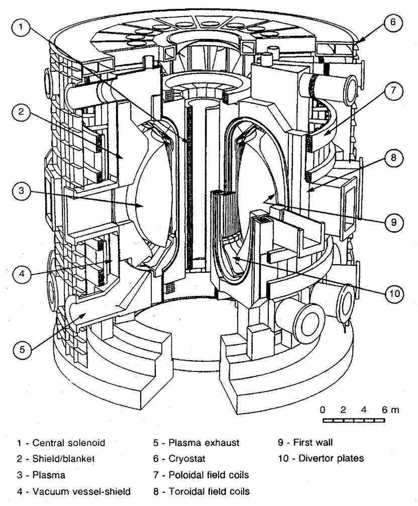
The design had the following main features:
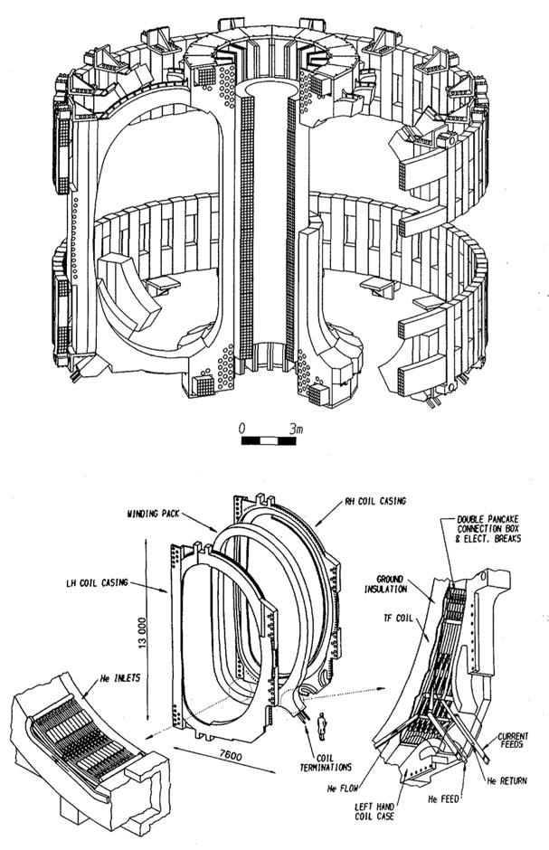
Magnets[[ 3]]:16 superconducting toroidal field (TF) coils and 14 superconducting poloidal field (PF) coils (arranged symmetrically about the plasma midplane), using Nb3Sn for the TF and central solenoid (CS) coils with a critical current density of up to 800A/mm2 at 12 T, 4.2K and zero strain, and selecting a cable-in-conduit conductor (CICC) concept, as shown in Figure 7.1.2. As a reference, the TF coils would be wedged against each other on their central leg, with bucking on a central cylinder or the CS as an alternative. For the CS, both layer and pancake winding were considered, with selection planned for the Engineering Design Activities (EDA) to come. NbTi was to be used for the (outer) PF coils because the magnetic field is less than 7T, again selecting the CICC concept. Forced-flow cooling by supercritical He was selected for all magnets because of the mechanical and electrical insulation requirements. To protect the magnets in the event of an accident, a terminal to terminal or terminal to ground voltage of up to 20kV was specified, meaning a choice of conductor current in the range of at least 30 - 40kA was desirable for most coils[ 4] Refrigeration capacity of about 100kW at 4.5K was considered sufficient to accommodate nuclear, eddy current, thermal-radiation, and conduction heat loads while allowing reliable operation of the magnet systems. The cryogenic system would be divided into modular units with capacities of 20 – 30 kW each, giving an overall refrigeration efficiency of approximately 300W expended at room temperature for every 1W absorbed in the magnet systems at 4.5K.
Vacuum Vessel: The vacuum vessel (VV) was an assembly of 16 segments with parallel ends ("parallel segments"), under the TF coils, and 16 wedge-shaped pieces, between them. The toroidal segments were single thick-walled and had electrically insulated connections to supporting structures located in the cryostat vacuum space and sealed from the primary vacuum by resistive elements. The toroidal resistance was 20µΩ[ 5] The VV was water-cooled, but helium coolant would be used for vessel bakeout[ 6]. The maximum helium concentration in joints, generated by radiation, would be below 1appm.
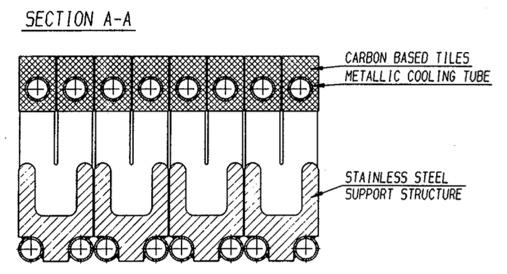
Plasma-Facing Components 3: A double-null divertor plate design featured armour brazed to poloidally oriented cooling tubes. In the Physics Phase, the armour was foreseen to be carbon-based material (see Figure 7.1.3). The first wall (FW) was integrated with the removable blanket segments so that a box-like structure was achieved. The FW was protected by carbon-fibrecomposite tiles, attached mechanically to the first wall, and cooled by radiation and/or conduction to the structure. In the Technology Phase most tiles would be substituted by a bare or tungsten- coated stainlesssteel wall5. The FW would be cooled with water at a temperature less than 100°C. The divertor would be cooled by high-velocity (10m/s) water.
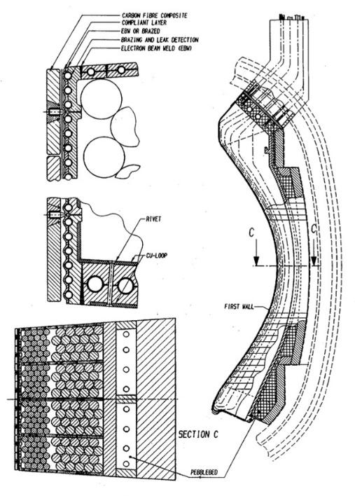
Shielding Blanket3: The FW, blanket and shield (Figure 7.1.4) were integrated into a single unit with separate cooling systems. A passive stabilization structure of closed copper loops attached to the outboard blanket segments above and below the horizontal ports was used to aid plasma vertical stability[ 7] Poloidal and toroidal coolant flow was chosen for the inboard and outboard FW, respectively[ 8] The inboard blanket was divided into three submodules per segment with two segments per sector to accommodate electromagnetic loads predicted during a disruption. The outboard blanket was divided into three poloidal segments per sector with the central segment divided into upper and lower modules to provide for the major penetrations. All blanket segments were manifolded at the top except the lower central outboard segment which was manifolded at the bottom. Austenitic steel (Type 316 solution annealed) was selected as the reference structural material. Shielding capability was set by limiting the dose to the TF coil insulator < 2x10⁹rad and to copper stabilizer < 5×10⁻⁴ dpa. Fast fluence (E > 0.1MeV) to the superconductor should be < 1x10¹⁹n/cm2 Local heat deposition in the coil winding pack should be ≤1W/cm3 Integral nuclear heat in the TF coil system should be <12 kW.
Fuelling: A combination of gas puffing in the divertor region and pellet injection past the scrapeoff layer provides fuelling and density profile control[ 9] .
Vacuum Pumping: Magnetic bearing (oil free) turbomolecular pumps (TMPs) or cryopumps (CPs) were foreseen arranged in eight pumping stations around the torus (24 CPs or 64 TMPs in total)9
Heating and Current Drive: Reference heating methods: electron cyclotron waves (EC-20MW, 120 GHz), lower hybrid waves (LH-50MW, 5GHz) and neutral beams (NB-75MW, 1.3MeV)[ 10] Alternate heating scheme: electron cyclotron waves (EC-20MW, 120 GHz), ion cyclotron waves (IC-115MW, 15-80MHz), lower hybrid waves (LH-50MW, 5GHz). The EC system would comprise 24 RF channels[ 11] The LH system would use two launchers, made up of 16 rows of 100 waveguides, and would occupy the lower half of two adjacent ports. The NB system would comprise nine modules, arranged in three vertical arrays of three modules. A vertical array of three modules would be aimed through a port which is aligned at a tangent to the magnetic axis of the tokamak. Each module would generate 8.3MW of deuterium or hydrogen neutrals. The IC system would be made up of a linear array of 42 antennas distributed around the torus. Two antennas were located side by side in the top half of a standard port and an additional antenna set was integrated into the blanket segments on either side of a port.
Cryostat: The cryostat would be a fully metallic welded design, with reinforcing ribs supporting a thin-shell body (effective thickness~ 10mm). The cryostat would support local shielding to permit at its exterior surface personnel access 24 hours after machine shutdown. Local ferromagnetic shields would be adopted for some components (i.e. pumps, NBIs) to reduce the magnetic field to the permitted values[ 12]
Machine Support: Coils and VV supports were of multi-leaf design which provides the best radial flexibility to accommodate differential thermal expansion whilst being able to resist buckling or rupture under the high compression loads3. The magnet system supports need to be compatible with the maximum allowable heat loss requirements. No shimming is permitted on the supports during the assembly12
Fuel Cycle: A fuel cycle inventory in the range 1-3kg of tritium (excluding inventories in plasmafacing components and the blanket) would be required.
Breeding Blanket: The design goal was a tritium breeding ratio of 0.8-0.9. A lithium ceramic (solid breeder) concept was the first option with a lithium-lead breeder blanket concept as an alternate.
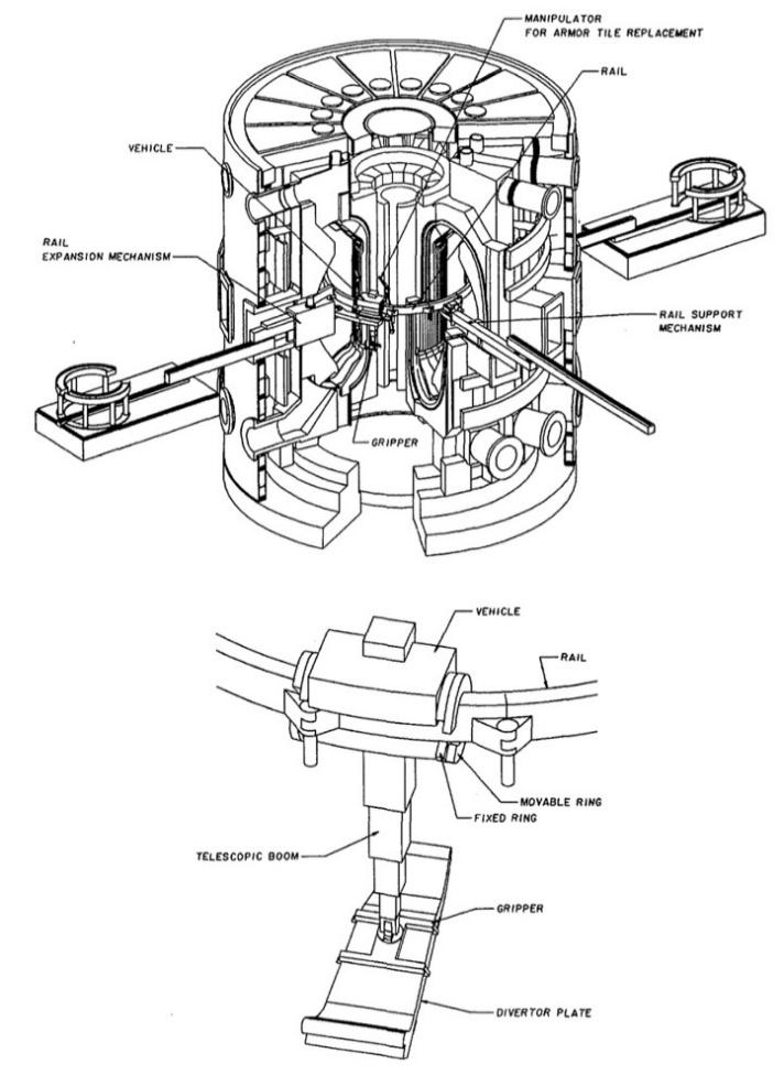
Remote Handling3: A combination of vertical and horizontal access (Figure 7.1.5) was planned for the blanket and shield modules[ 13] This required a segmentation scheme that allows removal of the inboard modules independently from the outboard. This scheme required two inboard and four outboard blanket modules, three upper shield plugs, and a lower semi-permanent shield module. Divertor plates and local FW repairs would be carried out using an in-vessel handling unit (Figure 7.1.6) installed via the equatorial ports. To accommodate maintenance and assembly procedures, the divertor would be segmented toroidally into two modules per sector2 The need for remote maintenance led to segmentation into 64 divertor plates and 96 FW/blanket units. Regular maintenance and/or replacement of the in-vessel plasma-facing components would be accomplished without warm-up of the magnet systems and would be performed in an inert-gas atmosphere to preclude contamination of the first wall. The VV must also be fully remotely
maintainable. A system of double-sealed doors would be used to avoid spread of activated material during transportation to the decontamination and repair/disposal facilities.

Tokamak Cooling: The piping and manifold layout would use four loops for each individual system, each loop serving one quadrant of the machine6
Safety/Confinement Approach [ 14]: Minimize first wall coolant outlet temperature to <150°C to limit overpressure. Minimize maximum first wall protection material temperature <1000°C to minimize the tritium inventory. Maintain an inert gas atmosphere around the vacuum vessel to prevent air ingress to the plasma. Develop a robust, fast (1s), and possibly passive plasma shutdown system/mechanism. The design target maximum release in the worst accident would be <100-200g of HTO. Tritium inventories were estimated to be about 800g in the beryllium of the blanket, 1-3kg in the fuel systems, 200g in the graphite (if at 1000°C), and possibly 1kg in the divertor plate redeposited materials. Double confinement barriers would �be used between the primary and secondary vacuum or the atmosphere at all vulnerable boundaries 1st barrier: VV; 2nd barrier: cryostat and casks; 3rd barrier building. The building would provide radiation shielding and control the release of radioactivity to the environment during routine operation, maintenance
and postulated accidents, and would be designed to protect against earthquakes. The thickness of the outboard blanket/shield/vacuum vessel would be enough to permit personnel access outside the tokamak 24 hours after shutdown, provided extra shielding was placed around penetrations.
Hot Cell: Would be used for inspection, sampling, decontamination, possible repair and graphite dust processing. Input expected to be 200t/y steel and 15t/y graphite (if all graphite PFCs).
Equipped building volume 120,000m3 .
Site requirements6: Electrical: continuous electrical power up to 250MW and an additional supply of up to 470MW for peak power demands. A desired power rate of change of 200 MW/s for power levels below 200MW, and 60MW/s for power levels above 200MW. Cooling: an ultimate heat sink with a capacity of approximately 1800MW. Transportation: heavy load access to national and international heavy haulage routes for loads up to 10m wide and up to 300t. For water transport, widths up to about 30m would be desirable. Site: ground conditions must support transport of plant gravity loads and have a bearing capacity of around 50t/m2.
Changes to Technical Objectives
Adjustments were made to the project technical objectives by the stakeholders at the start of the EDA. At the general level, it was decided that the aim should be to keep device costs "within limits comparable to those of the CDA ITER", and to maintain ITER's impact on the long-term programme (i.e. being the single step to a demonstration plant). The design should be confirmed by the scientific and technological database available at the end of the EDA (this later stimulated the development of the ITER Physics Basis[ 15] mainly through the working of the ITER Tokamak Physics Activity (ITPA)). Steady state operation was no longer considered the ultimate objective, but a demonstration was to be aimed at. The inductive pulse capability should be at least 1000s, with 2000s desirable. Validation of engineering was to focus on demonstrating the essential fusion reactor technologies (e.g. superconducting magnets and remote handling). Testing of reactor-relevant tritium-breeding blankets should focus on demonstrating the ability in a future reactor to achieve a TBR>1, high grade heat, and electricity generation.
Operation would continue to be planned for two phases: a Basic Performance Phase (BPP) lasting 10 years with a few thousand hours of DT operation, to address controlled ignition, extended burn and steady state operation (using initial heating systems), and blanket testing, followed, after a positive review of progress so far, by an Enhanced Performance Phase (EPP) also lasting 10 years improving overall performance (with a potential H&CD upgrade) and conducting higher fluence component and materials testing, and which may demonstrate a reactor-relevant blanket. The BPP would rely on external tritium supplies, and the progress of the EPP would depend on blanket breeder testing results and the availability of external tritium. There would no longer be a reliance
on ITER breeding tritium. Regarding availability, the BPP should enable continuous testing for 3–6 days, extended to 1–2 weeks during the EPP.
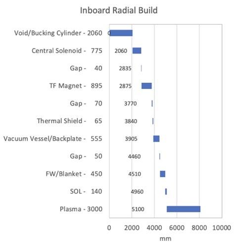
These new objectives, in the hands of a new Director (P-H. Rebut), now individually responsible for the design choices, unlike the four-headed Management Board led by K. Tomabechi during the CDA, were taken to require a machine somewhat larger than that of the CDA to accommodate the volt-seconds needed in the central solenoid (CS) for the longer burn time. However, the Director's experience in JET, from its conception through to its operation, also encouraged him to advocate increased engineering and physics margins, with an even larger machine, a "thermonuclear furnace", which would be more certain to ignite. To keep the ensuing costs down, the design would be standardized and simplified wherever possible, and auxiliaries (such as additional heating) would be limited to the minimum. The main parameters and cross section are shown in Table 7.1.2.1 and Fig.
Table 7.1.2.1. Main Parameters of the EDA Outline Design
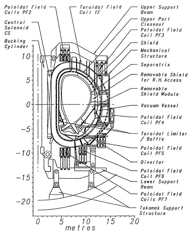
The main design changes were as follows:
Segmentation: 24-fold segmentation instead of 16-fold, for the TF coils and vacuum vessel, to maintain low field ripple at the plasma outer edge, despite its proportionately larger occupancy of the TF coil enclosed volume and thus the greater use of the toroidal field energy.
Divertor: Single-null, both for simplicity and to provide the maximum space for the divertor assembly (Figure 7.1.2.2).
The concept was for a "gaseous" divertor employing recycled gas reinjected perpendicular to the divertor channels which, in high-density operation, could "extinguish" the plasma in front of the divertor-plate, thereby distributing the power flow by radiation and chargeexchange over the entire surface area of the divertor channels, and using a baffle or angled plates (for example wing-like louvered structures at 45° in the toroidal direction to the magnetic field lines and 10 cm from the last flux line entering the baffle) to stop gas backflow into the plasma.
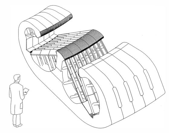
The use of beryllium instead of carbon was envisaged as the high-heat-flux plasma-facing material
for divertor components. The divertor would be subdivided into "cassettes" which could be replaced through the lower ports, in contrast to the in-situ repairable divertor plates of the CDA.
Volt-seconds: Increased to provide a 1,000 second inductive pulse.
Size: Increased to maintain confinement capability while adopting a lower, more conservative value for plasma elongation and a larger divertor volume.
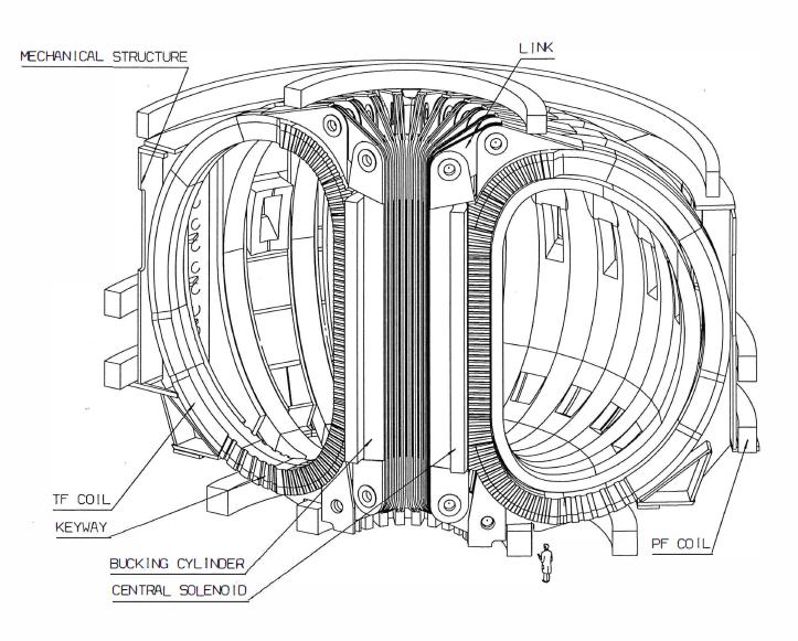
Performance: The strength of the toroidal field, both at the coils and at the plasma, relative to their values in the CDA design, was increased to maintain performance. Based on empirical plasma confinement scaling developed during the CDA, the EDA ODR design would have slightly more confinement capability than the CDA device.
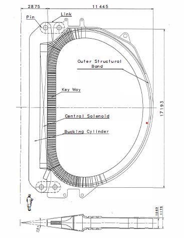
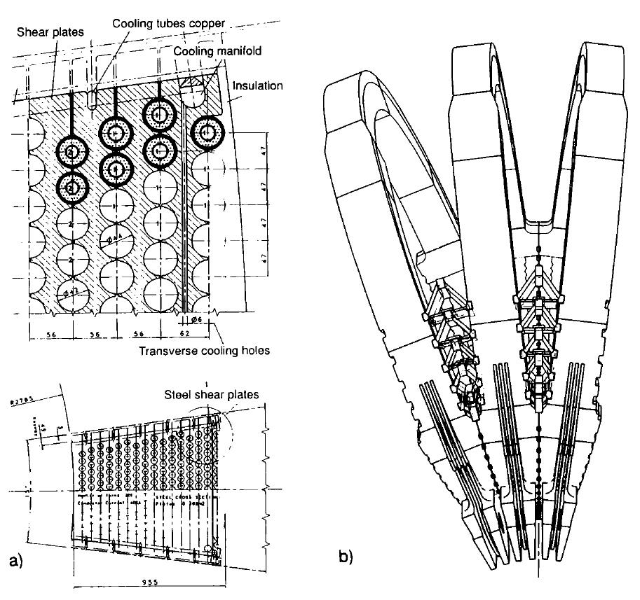
Magnets: A new design concept (Figure 7.1.2.3) was proposed for the TF and PF coils, using layerwound CICCs to allow all connections to be external to the core of the tokamak. The TF coils and the CS with its inner bucking cylinder would be mutually supporting (Figure 7.1.2.4). The inner bucking cylinder would be composed of a collection of nested, insulated, wedges which are individually pinned to links at the top and bottom. The wedges would be inserted into the solenoid after the solenoid was wound and would be an integral part of the CS subassembly. Each link would also be pinned to the outer structural band of each TF coil in order to carry some of the
vertical tension loads on the TF coil. This approach was intended to provide greater compactness, at the cost of more difficult manufacturability and added complexity.
Heating: A reduction to 50MW, with ion cyclotron heating being preferred (although the design could accommodate the other schemes). The choice of a single scheme and the reduction in power versus the CDA would give considerable cost savings. The Ion Cyclotron Resonance Heating (ICRH) system was envisaged to be possible to upgrade to 100MW without changing the antennae
Cryostat: Now a double-walled steel structure (to allow a vacuum test during construction (Figure 7.1.2.5), with bolted cover, built around the machine, which acts also as a shielding component and containment structure (up to 0.5MPa overpressure capability). The inner wall would be covered with superinsulation on the machine side. The filling could be sand or water to provide radiation shielding.
Vacuum Vessel: Now double-walled and fabricated from 24 toroidally continuous Inconel segments, welded between ports and filled with steel balls and coolant. It also would act as a shielding component and containment structure. Access ports were provided at three levels, upper (for shield/blanket installation and replacement), equatorial (for heating and current drive, blanket module testing, remote handling and diagnostics), and lower (for divertor operations and pumping).
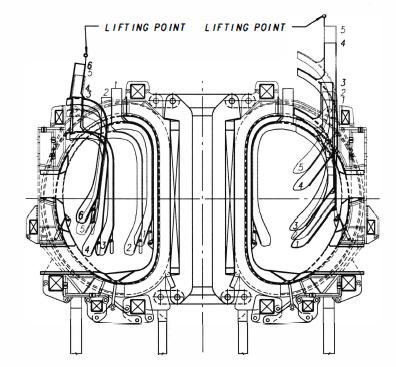
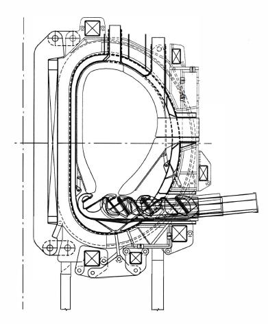
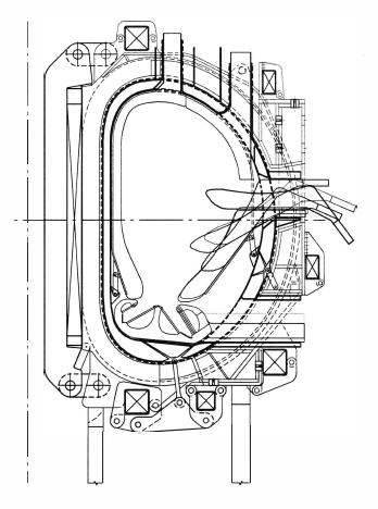
Remote Handling: New approach for the divertor, now in cassette form removed through lower port. Adjusted vertical maintenance through upper port for blanket, with test blanket (also shield blankets below ports, heating antennae and diagnostics) maintenance through equatorial ports (Figure 7.1.2.6).
First Wall: Planned to exclude all graphite first-wall materials, thereby eliminating a potential safety concern by reducing in-vessel tritium inventory and improving neutron fluence capability in view of the degradation in thermal conductivity of graphite under intense neutron irradiation. The undulated thin copper first wall was equipped with beryllium bumper limiters (solid Be bars) at the tips
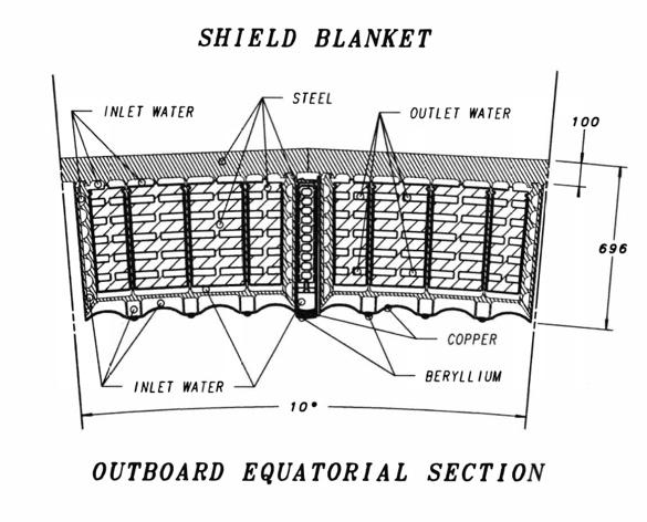
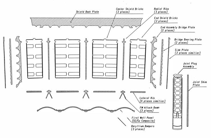
Shielding Blanket: (see also box) The outboard water-cooled blanket-shield design concept (Figure 7.1.2.7) featured blanket-shield modules approximately 5° in toroidal extent with a thick back plate (70 mm). The modules were welded together at the back plate forming a toroidally continuous assembly. A joint plug assembly was to be installed over each module-to-module joint. Each module would have one set of inlet/outlet cooling lines. The joint plug assembly would be a narrow protruding blanket-shield module with its own set of inlet/outlet cooling lines. All components would be 316 stainless steels except the FW panel which would be a bonded composite of copper (Cu-1Zr-1Cr) and 316 SS. The inboard modules would be similar but are approximately 7.5° in toroidal extent. The composite wall was toroidally undulated to reduce the primary stresses due to the coolant pressure and disruption loads, which could each approach 2MPa.
Breeding Blanket: Like the blanket-shield design except being a self-cooled liquid lithium system with vanadium structural material. Self-healing electrical insulator would be used to reduce the MHD pressure drop in the system. Liquid lithium would be used as breeding material and coolant. To improve shielding and ensure tritium self-sufficiency, a layer of beryllium would be incorporated in the blanket. Tritium recovery from the blanket would be feasible while maintaining a low tritium inventory. The typical lithium coolant velocity required to remove the nuclear heating and the surface heat flux would be about 2 m/s. An insulating layer (possibly aluminium nitride) on the surfaces of the coolant channel would prevent induced current to flow through
the channel walls. Vanadium alloy (V-5Cr-5Ti) was considered as the structural material. Tungsten carbide would be used as shielding and would permit rewelding the vacuum vessel during the ITER life of 3 MWa/m2 average neutron fluence.
The need to develop essential reactor technologies not only implied superconducting magnets and remote handling, and obtaining a full understanding of how to operate a successful divertor, but initially encouraged envisaging power-reactor-relevant materials for the blanket and in-vessel components, with a view to making an easier transition to a more meaningful test of operation of a breeding blanket during the EPP. This was proposed to TAC2 in March 19931, and discussed in more detail at a technical meeting in March/April 19932.
The initial thinking was that the first wall needed to be bakeable to 300°C. A structural material that could withstand more than the 10dpa and 400–450°C water-cooled operating temperature typical for austenitic steel would thus be desirable, and beneficial in the longterm development. Ferritic steels could be a possibility, but control of the ductile to brittle transition temperature would be an issue going forward. This therefore led to the consideration of vanadium for the structure, cooled by helium or liquid metal, either NaK or liquid lithium.
The need for such a high temperature first wall was disputed, particularly if it was not carboncoated, and temperatures of 150-200°C, compatible with water cooling, could be adequate. Liquid metal coolants had their own issues of safety/licensing and corrosion, as well as MHD (magnetohydrodynamic) effects on pumping (even though the use of LiPb eutectic was being considered as a possible breeder blanket solution). Furthermore, while the existing R&D to establish the materials database for austenitic steel in ITER was nearing completion, there was little or no data on materials such as vanadium under the necessary conditions, so a new materials R&D programme would be required, in facilities not yet planned, at increased and unplanned expense, causing unspecified delay. The logic of trying to maintain a single structural solution for both the BPP and EPP was therefore abandoned, under the expectation that a full blanket replacement at the end of the BPP "might open new paths". The design would proceed using water-cooled austenitic steel.
1 TAC-2 Minutes
2 Technical Meeting on Blanket/First Wall Design, Coolant, Structural Materials and Integration with Vacuum Vessel, Garching, March 31–April 9 1993
Safety Approach: Fast recycling of fuel to minimise the tritium inventory.
Hot Cell: Similar requirements to CDA.
Changes to Technical Objectives
There were no changes at this point, but a new Director (R. Aymar).
Design Changes
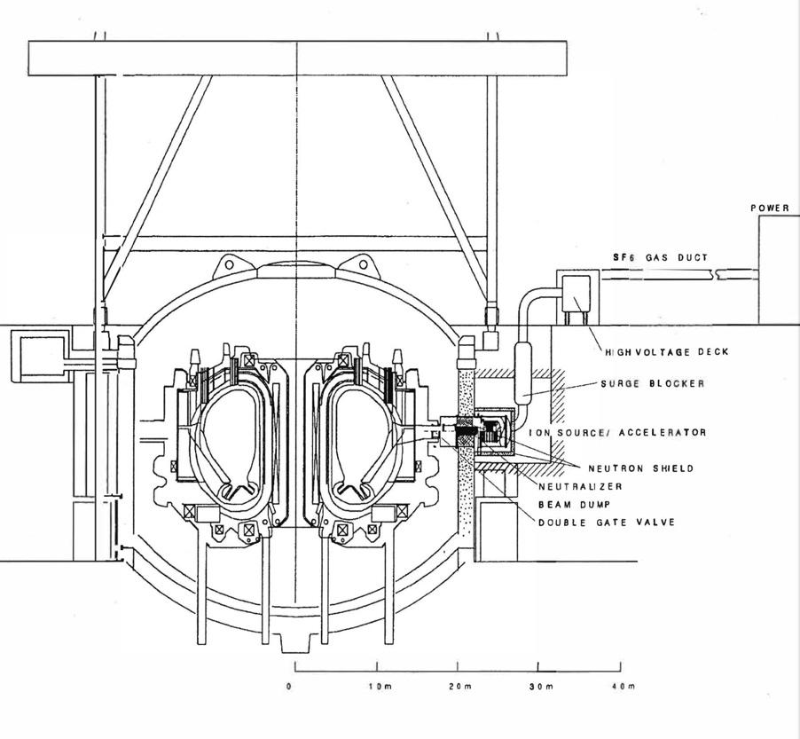
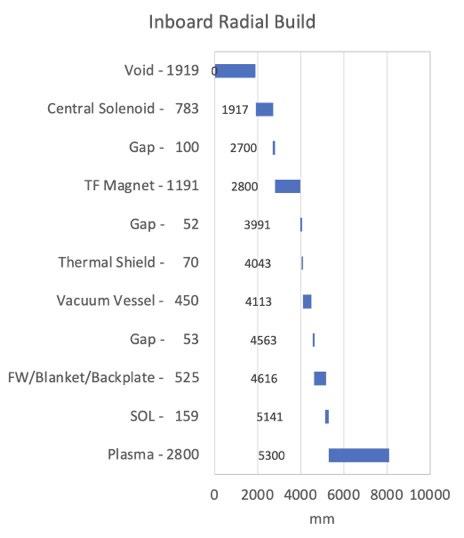
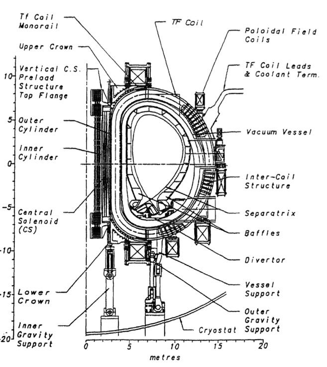
The Interim Design reflected an improvement to the Outline Design (OD) from the standpoint of manufacturing, assembly, maintenance, safety and reliability by a joint effort of the Joint Central Team and the Home Teams[ 16],[ 17]. The main features are shown in Table 7.1.3.1 and Fig 7.1.3.1
Table 7.1.3.1 Main Parameters of the EDA Interim Design
Plasma major (mid-plasma) radius (m) 8.1
flux capability (Vs)
Segmentation: Reduced from 24-fold to 20-fold to improve access to the VV for remote maintenance.
Magnets: In the outline design, to maximise the plasma cross-section for a given machine size, the toroidal field coils consisted of thin, jacketed conductors embedded in poloidal shear plates. To increase stiffness, torsion was taken up by a cylindrical structure through shear keys. But there were disadvantages, notably difficult maintenance of the central solenoid (CS) owing to the small gap to the toroidal field (TF) coils, the large weight of the CS assembly (3000t) requiring a special crane, and for the TF coils difficulties in the assembly of the poloidal shear plates. In the interim design, the TF coils were now provided with casings and radial shear plates, the increased bending stiffness allowing a simpler mechanical structure. The new stiffer and simpler coil design included thin, jacketed conductors embedded in grooved radial shear plates enclosed inside a strong steel case. The coils would be manufactured using the "wind, react, transfer" technology. The new CS assembly, including two torsion cylinders, would now have a weight of 1350t. The layer-wound CS coil would continue to support a significant fraction of the TF coil centring force. The PF coils would contain redundant modules, allowing them to be disconnected on failure and the coil run at the same current at a lower helium temperature. Ultimately it should be possible to rewind any of the PF coils in situ. The 5 largest PF coils would need to be wound on site.
Vacuum Vessel: A double-walled water-cooled ribbed structure (instead of balls) would be made of SS 316 LN to ease licensing. The vessel cooling was designed to provide decay heat removal by natural water convection even when in-vessel component cooling was not working. Since stainless steel is not as strong as Inconel, thicker plates for the double shell and a larger thickness of the double wall structure in the critical lower part of the vessel were required. Therefore, less space was available for the divertor, reducing the poloidal length from the X-point to the target from 2m to 1.8m. To limit additional stresses due to a loss of coolant accident inside the VV, a suppression tank with a rupture disk was introduced below the tokamak, to keep the internal pressure to < 0.5 MPa. The vacuum vessel would be manufactured in 40 sectors and assembled each side of a TF coil with welds in the plane of the TF coil. The combined weight would be 1400t. The vessel and contents would be hung from the TF coil structure.
First Wall/Shield: The outline design blanket required cuts and welds (100mm thick) between adjacent blanket modules during remote replacement of a faulty blanket. The blanket system now consisted of a back plate, with a manifold and 2m x 1m FW-shield modules fixed to it. Each of the 720 modules would be attached to the backplate by bolts which could withstand the tension loads during disruptions (~1.5MPa). The shear loads resulting from currents flowing through the side walls of the modules would be sustained by a key structure on the modules mating to a key slot on the backplate. The cooling water would be supplied to the module by inlet and outlet pipes which were welded from inside the manifold by an in-pipe remote handling machine. Maintenance of the FW-shield modules would be performed by an in-vessel transporter inserted through the midplane port. Both the structural and shielding materials would be SS 316 LN. The heat sink material would be a Cu alloy. The cooling pipes would be SS 316 LN in the first wall, except at the limiter and the baffles where they were Cu alloy with a SS liner. During assembly, the blanket backplate sectors (3 outer and two inner modules) would be welded together to form a horseshoeshaped section. Then the FW-shield modules would be partly preassembled onto the backplate and the horseshoe transported to the pit where it would be inserted (rotated toroidally) into a completed section of the VV. When in its final position it would be jacked up and finally welded to the other blanket sections. This would minimize the assembly of FW-shield modules as well as backplate welds inside the VV. The toroidal belt limiter for start-up and shutdown would consist of a special FW module below the midplane
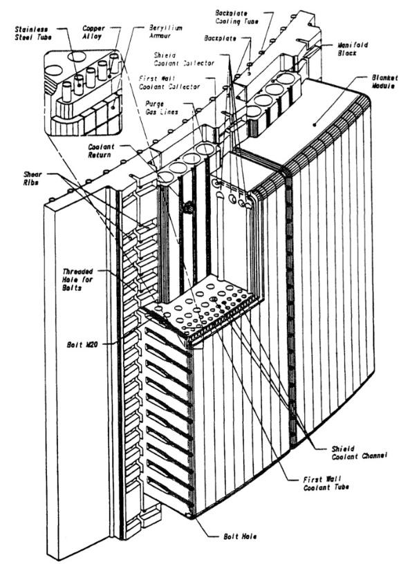
port. It would be designed for a maximum heat flux of 5 MW/m2 and thus able to remove 20 MW of total power including peaking due to misalignment. The other FW modules would be designed for a maximum heat flux of 0.5 MW/m2 except for the baffle modules at the divertor entrance which would also be designed for 5 MW/m2 to withstand the high radiation loads expected there. All the FW modules would be clad with 10mm thick Be tiles providing protection against transients such as vertical displacement events.
Divertor: 60 cassettes (3 per sector) cooled by straight radial pipes. An improved maintenance concept based on toroidal and radial rails would allow a full divertor changeover in less than six months. The high heat flux components would consist of a 100mm thick stainless steel backplate on which were mounted copper alloy monoblocks brazed to a copper alloy tube containing a swirl tape. These would be designed to withstand attached plasma (up to 20 MW/m2) for short transients. The monoblocks would be clad in either C, Be or W, as considered appropriate. Just below the null point a dome would be provided to intercept the plasma separatrix in case of plasma vertical displacement events and to provide additional neutron shielding. Below the dome, in the so called “private region”, two semi-transparent walls made of wing-like structures tilted by 45 degrees in the toroidal direction towards the incoming magnetic field lines would intercept the thermal radiation and the high energy particles, while providing enough conductance for the flow of cold neutrals. The divertor would be designed to take a stationary power load of 300MW.
Remote Maintenance: The modular approach to blanket design led to a change in blanket maintenance strategy as it could offer advantages with respect to weights to be lifted, spare parts needed, and maintenance time. Instead of vertical blanket maintenance of large banana-shaped blankets through upper ports, blanket maintenance would be by in-vessel transporter inserted through the equatorial ports. The large upper ports could then be reduced in size as they would no longer be required for blanket maintenance. The equatorial ports were somewhat enlarged due to their more extensive role in blanket maintenance, and were connected by cylindrical bellows to the cryostat.
Cryostat: The bio-shield function would now be provided by the building concrete outside the cryostat. The cryostat remained a double-walled stainless-steel shell, each now 20mm thick, with a 200mm interspace which could be compartmentalized and filled with helium for leak checking. There would be over 400 penetrations.
Heating: Upgraded from 50 to 100 MW to enable H-mode access and to increase the current drive capability. The likely combination would be fast-wave ion cyclotron, neutral beam, and electron cyclotron resonance heating, though lower hybrid heating was not ruled out. It was not essential to make a choice yet.
Performance: The performance was now estimated based on physics rules developed by the participants' physics experts. While the above changes somewhat reduced the margins for
ignition, beta, and burn duration, the physics performance of the Interim Design and of the Outline Design were considered comparable. The slightly reduced plasma radius and current (maintaining the plasma safety factor q95 at 3) was compensated by an increase in plasma elongation. This would require a higher power for the poloidal field system to compensate for an increased vertical plasma instability growth rate. Probability estimates were made of ITER performance, showing that, due to the slow buildup of helium in the plasma, ignition was likely to be sustained for 1000s even without external heating, and was certain with 50MW of external heating.
Blanket Testing: Four midplane ports were reserved for test blanket modules. If desired, a full breeding blanket could be installed for the EPP by replacing the FW/Shield.
Power Supplies: The pulsed power supply system provided electrical power to the TF and PF superconducting magnets, and the auxiliary heating and current drive systems. During operations total peak demand would be 500–650MW active and 400–500MVAr reactive power which was assumed to be provided to the ITER site from a stiff, high voltage grid. A very large electrical plant would result: the total installed AC/DC conversion power for all the superconducting magnet systems would be 2800MVA, and 300–400MVA for the auxiliary heating systems. In addition, a conventional steady-state power supply system would be required able to deliver up to 230MW, to the ITER support systems, notably the water-cooling systems and the cryoplant.
Safety Approach: The design was analyzed by the JCT and Home Teams to provide a failure modes and effects analysis, to assess the implementation of the key functional requirements in the design, and to estimate release impacts and confirm site personnel safety.
Hot Cell: The location was defined in building layout. Hot cell waste estimates were 500m3 (prior to segmentation) in 20 years, and activity 4–40 TBq/m3
7.1.4
Changes to Technical Objectives
There were no changes at this point.
Design Changes
The main design parameters remained unchanged from the Interim Design. The main features are shown in Table 7.1.4.1 and Figure 7.1.4.1.
Table 7.1.4.1 Main Parameters of the EDA Detailed Design
Plasma major (mid-plasma) radius (m) 8.1
Plasma minor radius (m) 2.8
Elongation (ratio of plasma height to width) 1.6
Toroidal magnetic field at mid-plasma (T) 5.7
Nominal maximum plasma current (MA) 21 MA
Nominal fusion power (GW) 1.5 Pulse length (s) >1000
Average 14 MeV neutron wall loading (MW/m2) 1.0
Inductive flux capability (Vs) 530 TF coils nuclear heating (peak kW) 15.5
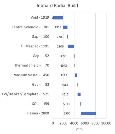
Further changes from the Interim Design included:
Performance: Nominal operational scenario: breakdown with ECH assist followed by 150s current ramp up until the divertor configuration is formed at ~16 MA; 100 MW heating and plasma density increase then applied to reach H-mode and nominal fusion power; at the end of burn normal fusion shutdown would take place over 300s. Operation with saw-toothing ELMy H-mode was used for projections. The burn could be extended to 8000s with 100MW auxiliary power by dropping current to ~16MA and power to ~1GW. Using "reversed shear", true steady state operation could be achieved at 12–15MA. The machine should be capable of 50,000 cycles.
Magnets: Correction coils were added around the TF coils to adjust for assembly and manufacture misalignments and to avoid "locked modes" in the plasma. Two Large Projects (L1 and L2) were introduced to carry out R&D on the TF and CS coils.
Vacuum Vessel: A Large Project (L3) was introduced to focus R&D.
Divertor: The divertor plasma would be operated in the detached or partially detached regime. Radiation losses would be enhanced by gas puffing with Ne or Ar. This would reduce the peak heat flux to 5-10MW/m2. A Large Project (L5) was dedicated to divertor manufacturing R&D.
Layout: The tokamak building and pit, and the layout of peripheral equipment, were reconfigured to more efficiently use the space around and below the tokamak. A seismic isolation option for the pit was developed able to withstand a ground acceleration significantly greater than the expected site specification of 0.2g.
Safety Approach: Dedicated galleries were provided for specialized functions in the surrounding building, separated by radiological barriers and minimising the number of penetrations crossing the seismic isolation. A first comprehensive Non-Site-Specific Safety and Environmental Assessment of ITER was carried out with Home Team (HT) experts, showing that ITER successfully met all ITER safety-related design requirements.
Cryostat: Shape altered to improve use of space.
Remote Handling: Procedures optimized to make maximum use of hands-on maintenance consistent with the ALARA-principle, and access to remote handling ports through shielded cells. Two Large Projects (L6 and L7) were dedicated to divertor and blanket R&D.
Heat Transfer: Optimization of number of loops, pipe routing, and safety.
Shielding Blanket: A Large Project (L4) was dedicated to manufacturing R&D.
Breeding Blanket: Primary candidate design for the EPP was assumed to be lithium ceramic with beryllium multiplier. This would use the same cooling circuits as for the BPP, and should achieve a TBR>0.8, allowing 1 MWa/m2 to be achieved over the EPP with 1.5kg/year external tritium.
Buildings: Tritium, Electrical Termination, and Tokamak Services buildings were all reduced in size after more detailed design of internals. NB Power Supply building eliminated as supplies will be outdoors. Cold testing of magnets would be carried out at the factory, eliminating the magnet test facility. Supply routing improved.
Hot Cell: Hot cell equipped building of 310,000m3 considered.
Changes to Technical Objectives
There were no changes at this point.
Design Changes
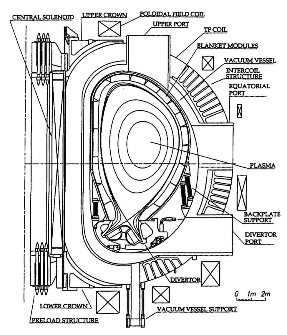
The main design parameters remained unchanged from the Detailed Design. Details are shown in Table 7.1.5.1. and Figure 7.1.5.1
Table 7.5.1.1. Main Parameters of the EDA Final Design
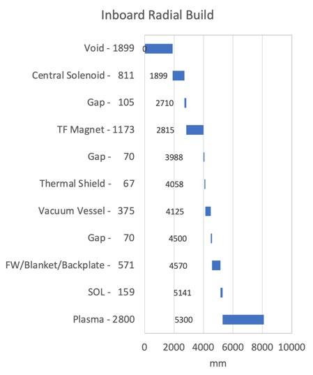
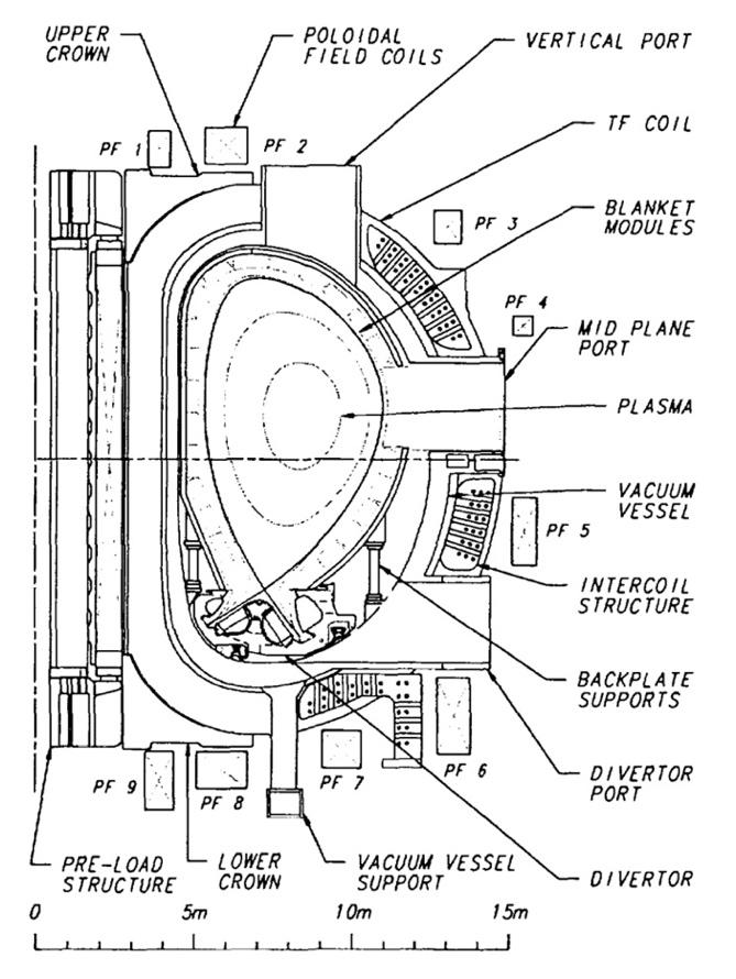
Further changes/developments since the Detailed Design included:
Magnets: The overall coil layout is shown in Figure 7.1.5.2 The number of poloidal field coils was increased from 7 to 9, to improve plasma shape control, add triangularity (at the top at least), and to allow all poloidal field coils to be made from NbTi superconductor. The magnet system was designed for 500 fast discharges during its lifetime. The CS has to be ready for recharging 2000s after a fast discharge if the coil did not quench. The magnet system was designed for 100 cooldown-warmup cycles. The epoxy resin systems were selected to withstand a total lifetime radiation dose of 10MGy. In the event of certain failures in other systems (e.g. cryoplant), the TF coils can be discharged with a 25–30-minute current decay time to allow a rapid, but controllable plasma termination, while avoiding a quench in the TF coils.[ 18]
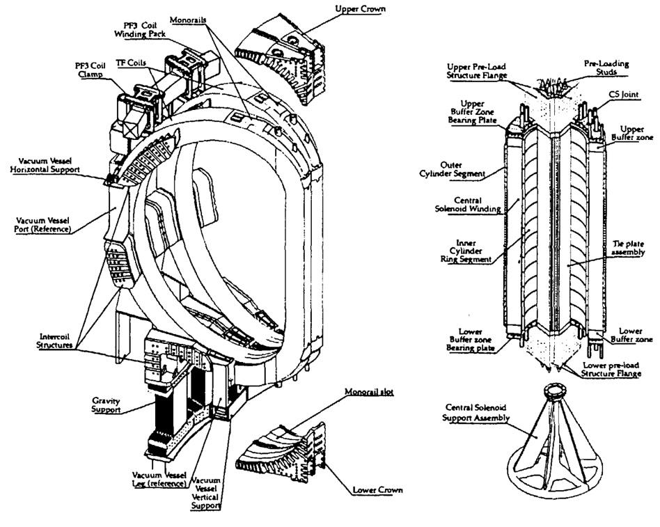
Vacuum Vessel:[ 19] (Figure 7.1.5.3)
Ferromagnetic inserts (SS430) were added to reduce still further the TF ripple in the plasma outer region, and careful attention was paid to ensure that adequate plasma control could still be achieved. The primary vessel shielding material was SS 30487 (with 2% boron). 40mm thick plates would be used in all areas (except where ferromagnetic inserts were used). The main vessel/shield combination and the blanket must have a combined toroidal resistance >4µΩ. The toroidal resistance of the vessel/shield assembly would be ~8.4µΩ. and combined with the blanket would be ~5µΩ.
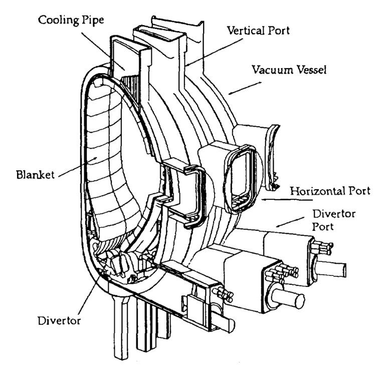
Port allocation: Equatorial: 3 NB, 5 RF, 4 TBM, 4 Diagnostic, 4 RH (shared with limiter and additional diagnostics).
Shielding Blanket:[ 20] 739 now (was previously 720) modules due to the need for special modules around the NBI ports. The Be coated FW would be designed to dissipate 0.5MW/m2. The (Wcoated) baffle modules at the divertor throat must tolerate 3MW/m2, and the limiter modules 810MW/m2. The complete blanket system should have a leak rate <10-8Pam3/s. The blanket system (backplate) would be supported from the VV at 20 lower inboard and 40 lower outboard positions. The supports (Figure 7.1.5.4) would be flexible in the radial direction and stiff in the toroidal and vertical direction, thus providing thermal decoupling between the blanket and VV. Blanket module attachments to the now double-walled backplate were developed which were able to withstand electromagnetic, thermal and mechanical loads, yet allow all maintenance and installation of attachments and service connections to be carried out from the plasma side.
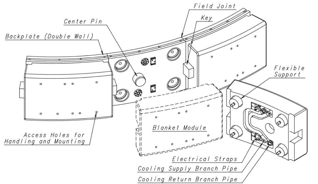
Limiter: The concept of a toroidal belt limiter was replaced with a port limiter at two or more equatorial ports, allowing better plasma control and simplifying limiter removal for maintenance.
Equatorial Port Systems: All (limiter, RF heating, diagnostics, test blankets) with plasma facing hardware would now be supported from the vacuum vessel port assemblies.
Divertor[ 21]: The divertor wings were removed to simplify the design and to simplify the cleaning of co-deposited tritium. The lower part of the vertical targets must tolerate 20MW/m2 for 10s, expected to occur up to 1000 times during the BPP. W and C are the main plasma-facing materials. The heat loads during disruptions would be ~100 MJ/m2 in 0.1-3 ms and those during giant ELMs ~10 MJ/m2. Optical diagnostics would be incorporated in 12 cassettes at four port locations. The divertor must withstand the thermal loads and the erosion from ion and charge exchange bombardment without the necessity of complete or partial repair for at least 103 pulses at nominal parameters including 200 full power disruptions. The cassette body must then at least withstand the neutron dose corresponding to 1MWa/m2 neutron wall loading at the outboard first wall. The cassette bodies must be re-usable for the entire life of ITER. The HHF components must at least withstand a neutron dose corresponding to 0.3MWa/m2 at the outboard first wall.
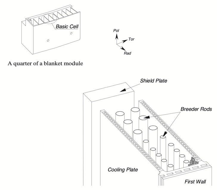
Breeder Blanket: A breeding blanket concept (Figure 7.1.5.5) for the Extended Performance Phase (EPP) was further developed, using lithium zirconate (with the backup of silicate or titanate) and beryllium pebbles, water-cooled.
Fuelling:[ 22] The fuelling system comprises systems for gas puffing, pellet injection and wall conditioning, and a fast fusion power shutdown system using deuterium or killer pellets. A continuous fuel pellet screw extruder was incorporated into the pellet injector system, which injects at one location (from two redundant units) into the plasma from the high field side. The gas injection system would be capable of injecting up to 6 gas species (3 hydrogenic, 1 helium and 2 impurity gases). The fuelling isotope mixture would be adjustable between 100% D and 100% H during H and D operation, and between 100% D and 90 % T during DT operation.
Vacuum Pumping: The integrated global leak rate into the primary vacuum boundary has to be less than 10-7Pam3/s. The torus high vacuum pumping system would consist of 16 cryopumps located in the divertor ports. The pumps would be regenerated during the plasma discharge to limit the tritium inventory. Each cryopump would pump for 900s followed by a 300s regeneration cycle. Pumps would be taken off-line sequentially for regeneration with a new pump starting a regeneration cycle every 75s. At any moment during plasma operations, 12 of the pumps would be pumping the plasma chamber exhaust and the other 4 pumps would be in various stages of regeneration. The net pumping of the torus high vacuum pumping system needs to be adjustable from 0–100% in <10s. The torus roughing system must be designed for the evacuation of the torus from atmospheric pressure to 50Pa in < 60 hours.
Wall Conditioning:[ 23] Bakeout temperature for all in-vessel components would be 200°C, with the blanket preferably bakeable to 240°C and the divertor to 350°C due to T deposition there. During baking the temperature of in-vessel components would be ramped up to the baking temperature at a rate of ~ 10°C/hour and held at this temperature for ~ 100 hrs or until the impurity partial pressure drops to <10-3Pa.
Heating: A design of a LH H&CD system for ITER was developed, although it was not yet fully integrated in the design for all machine services (e.g., power supplies and layout).
Diagnostics: Considerably more design work was done to integrate diagnostics into the in-vessel components. The diagnostic systems comprised about 40 individual measurement systems in seven generic groups: magnetic diagnostics (6), spectroscopic and neutral particle analysers (10), neutron diagnostics (9), microwave diagnostics (8), optical/IR (7), PFC and operational diagnostics (6), bolometric systems (2), diagnostic neutral beam (1). The design would allow for major disruptions, assumed to be about 3000 during the BPP, with about 500 at nominal parameters, 600 at full current and one-half the maximum stored energy, and 1900 with less than one-half of the nominal current and nominal stored thermal energy), and up to 1000 disruptions during the EPP. Cooling for diagnostic components inside the biological shield would be derived from the cooling circuits of major machine components and would be designed to operate at 150±50°C. All diagnostic equipment must be able to be operated remotely.
Cooling: The tokamak cooling water system and cryoplant were improved to take into account the large, pulsed heat loads they experience.
Cryostat: Design was changed to single wall with flat ends as a result of detailed analyses of loading conditions. The internal pressure under LOCA would be limited to 0.2MPa by an overpressure suppression system (rupture disks) venting to the stack.
Upper Ports: Alternating ports would now be used for diagnostics and for access for blanket cooling pipes.
Remote Maintenance: Further development of the concept (Figure 7.1.5.6 ).
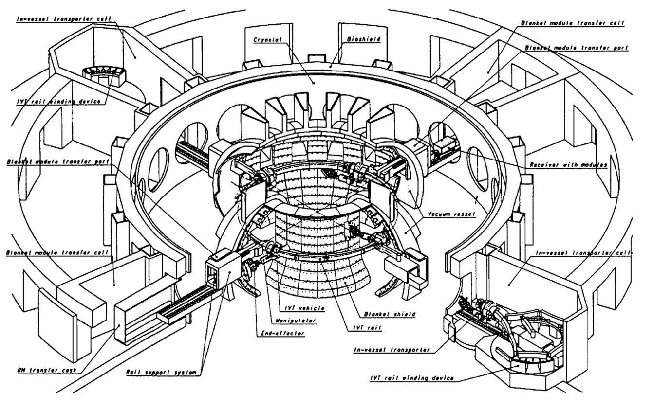
Fig 7.1.5.6. Blanket Module Replacement Scheme
Safety Approach: Updated and extended second version of non-site-specific safety analysis.
Hot Cell: Reduced in size and area vs DDR. Preliminary design and safety analysis carried out. Building 76m x 110m with two primary operating levels. ITER would be able to package materials in sealed containers so no further processing would be needed by host. 6 months storage capacity. Hot cell building size estimated at 244,000m3. Assumed all waste treatment and hot cell equipment can be procured after the start of ITER operation, i.e. the building is not equipped at start of operation.
The ITER participants' unwillingness to proceed with the implementation of the 1998 EDA design led to a study of the feasibility of producing an ITER design with reduced technical objectives and reduced cost (RTO/RC) (see Study of Options box below). The subsequently accepted design constituted the actual reference for the negotiation among the Parties, leading to the sharing of the responsibility for the procurement of the different parts of the plant, and for the subsequent formal tracking of design changes.
The general objective was to design a device costing 50% of the 1998 EDA final design. The necessity of ignition was replaced with the aim of Q≥10 in inductive operation (without precluding ignition), with a view to Q≥5 in steady state operation. As in the EDA, the design should be
confirmed by the scientific and technological database available at the end of the EDA (extension), i.e. supported by the ITER Physics Expert Groups. The design should be capable of supporting advanced modes of plasma operation under investigation in existing experiments and should permit a wide operating parameter space to allow for optimizing plasma performance. It should demonstrate the "availability and integration" of essential technologies and no longer demonstrate the safety and environmental potential of fusion power but operate safely and reliably.
Operation should continue to be planned for 20 years; the planned initial operation phase is illustrated in Figure 7.1.6.1. Operation modes should be determined having sufficient reliability for nuclear testing (without specifying a target of weeks of continuous operation). Low-fluence functional tests of blankets should be conducted early on. DEMO-relevant tests can then be conducted later in higher fluence/flux conditions. A few tens of thousands of pulses should be envisaged, limiting fatigue. The flat-top length should be in the range 300–500s. The average 14MeV neutron wall load should be halved, and a fluence of 0.3MWa/m2 should be designed for. Installing a tritium breeding blanket later should not be precluded, but the whole operation should be able to be accomplished using external supplies of tritium.
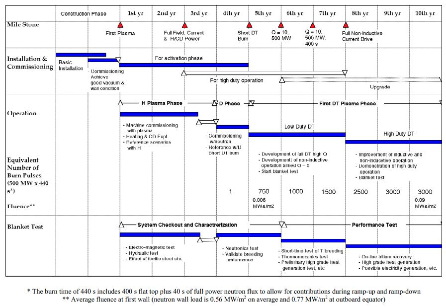
The changes in objectives necessitated considerable discussion and an evaluation of options was carried out (see box) between mid-1998 and the beginning of 2000 to converge on the design point (Table 7.1.6.1) and to develop it further, as far as possible using the design and still ongoing R&D carried out for the 1998 Final EDA design.
Table 7.1.6.1. Main Parameters of ITER EDA Extension Final Design
field
coils nuclear heating (peak kW)
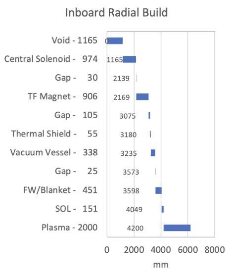
* This inductive flux in principle would allow reaching a plasma current of 17 MA
The design solutions of the EDA Final Design continued to be adopted except as follows[ 24]:
Segmentation: 18-fold symmetry.
Magnets: TF internally the same as in the EDA design, but now the coils would be fully wedged. The coils would be connected together by bolted structures, and by two compression rings made of unidirectional glass fibre, that would provide an initial inward radial force on each coil (2 x 30MN) which, through shear keys, would help in resisting out-of-plane loads. The CS would be segmented into 6 modules each composed of 3 double or 1 hexa-pancake, with currents individually controllable to provide more flexible plasma shaping. There would be 6 large PF coils made from NbTi double pancakes with redundant turns for trapped coils. Space available for intercoils structure would be reduced to maximise port access.
Divertor: Would operate in a partially detached mode, where power and momentum entering the divertor channel near the separatrix would be removed by radiation and charge exchange through interaction with neutrals and impurities before contacting the target. A generous fraction of in-
vessel space was allocated to the divertor in order to permit a relatively long divertor leg, which was necessary to permit sufficient interaction between neutrals and plasma to remove most of the plasma power and momentum near the separatrix. 54 cassettes.
Divertor Maintenance: Divertor cassettes would be loaded onto and unloaded from toroidal rails using a cantilever mover mounted inside a port transfer flask.
Port allocation: 3 equatorial ports for 3 heating NB and 1 diagnostic NB (but only 2 Heating NB initially installed), 2 ports for plug limiters, 3 ports for TBMs, 3 or 4 ports for RF heating (initially only 2 used for EC and IC), 4 TBM, up to 7 for plasma diagnostics (some shared with the port limiters), 4 RH (shared with limiters and additional diagnostics).
Cryoplant: Time-averaged heat load would be 55 kW.
Vacuum Vessel: 9 sectors. Toroidal one-turn resistance ~8µΩ. Would be cooled by 2 independent loops. Can still remove decay heat from in-vessel components by natural convection. Vacuum vessel pressure suppression system moved to above tokamak.
Vertical Stability: Would be assured by an active feedback position control system, changing the current in the largest 4 PF coils through a special power supply feeding them in an anti-symmetric way across the plasma equatorial plane. These changes would provide an additional radial magnetic field leading to the required vertical restoring force on the plasma. Additionally, copper cladding would be introduced on the vessel, and passive vessel-internal saddle coils or active coils inside the vessel may be needed.
Shielding Blanket: 421 modules. The backplate was eliminated. Blanket modules would be composed of single curvature faceted separate first wall elements mounted onto shielding blocks directly attached to the vessel through flexible supports. To ensure vessel reweldability the shield thickness must be ~45cm and gaps must be minimized.
Cooling: Vessel inlet temperature 100°C, blanket/divertor <150°C, temperature rises during pulse 9°C (vessel), 50°C (blanket), 40°C (divertor). Baking would be at 200°C (vessel) and 240°C (blanket and divertor). Heat released from the tokamak during nominal pulsed operation would be 750 MW.
Vacuum Pumping: 6 cryopumps beyond the divertor which can be shuttered for regeneration.
Heating: 73MW initially, up to 110MW maximum. EC, IC and (negative ion) NBI.
Power Supplies: Total pulsed active/reactive power from grid: 500MW, 400MVAr; Total steady state active/reactive power: 110MW/78MVAr.
Hot Cell: Due to the reduced total fluence there would be no need for high level radioactive waste disposal before the end of the plant operation[ 25] Thus, the hot cell building was considered necessary to a much-reduced extent and would only be equipped at start of operation for low level waste processing.
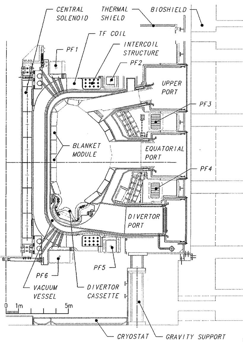
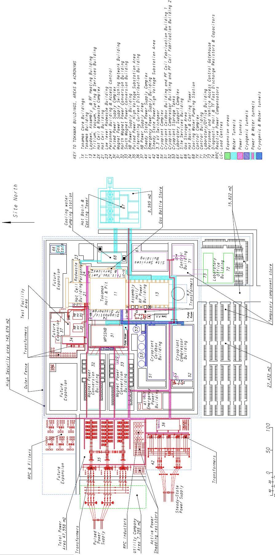
The vertical elevation of the machine is illustrated in Figure 7.1.6.2. and the layout of the ITER site is shown in Figure 7.1.6.3
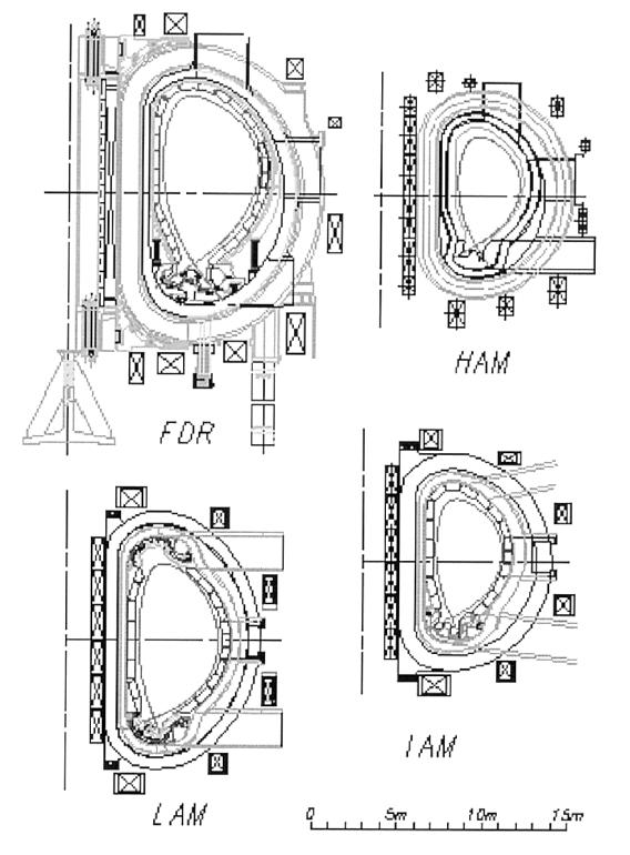
To provide a basis for the rigorous exploration and quantification of the issues and costings, three representative options were selected for deeper consideration and their parameters frozen:
o high aspect ratio machine (HAM and high TF) with similar configuration to the FDR.
o intermediate aspect ratio machine (IAM, high TF) with a single null divertor and a slightly vertically asymmetric magnetic configuration across the equatorial plane
o low aspect ratio machine (LAM, low TF), vertically symmetric, lower aspect ratio and able to support (if proved useful) a double null plasma.
These options appear to span the appropriate range of aspect ratio and magnetic field.
• The common features of LAM and IAM are:
o a reasonable operational margin of Q = 10
o a reasonable operational plasma density smaller than the Greenwald density
o higher elongation and triangularity to improve the density limit, and the beta limit
o confinement and superior capability of steady-state operation
• The specific features of LAM and IAM are as follows:
o LAM has better access, lower electromagnetic forces, better flexibility of plasma configuration such as the possible operation of double null divertor, and
o larger power threshold margin for L-H transition
o IAM has better capability for steady-state operation, higher Greenwald density and higher average neutron flux.
• Variants of IAM and of LAM were also studied, which have similar characteristics to those of IAM and LAM. In addition, a sensitivity analysis, spanning the range of parameters for IAM and LAM, was performed.
Main
The studies showed that reducing the technical objectives without changing the nature of the design would not be enough on their own to achieve the 50% cost target. Further design changes would be necessary. They should consist mainly of reductions, as far as is reasonable, in technical margins, and in improving/optimising engineering design towards reduced manufacturing costs, while at the same time, and very importantly, seeking to benefit fully from latest R&D results in physics and technology.
These study results were reviewed by TAC in mid-1999 and confirmed as a good basis for further convergence on design parameters. IAM and LAM were considered to cover the acceptable range of aspect ratio. The HAM example with its larger aspect ratio of 3.5 was rejected because it provides too limited access to the plasma.
Intensive joint work through the JCT/Home Teams “Integration Task Force”, then led to the choice of a single configuration for the ITER-FEAT design (IAM) which was confirmed by the TAC and IC in January 2000 in the ITER FEAT Outline Design for further development as representing an appropriate balance of the key technical factors and the cost target and the use of a conservative option for the energy confinement scaling.
Pending a site decision and completion of the negotiation on the sharing of the procurement among the Parties, several outstanding issues were identified and in some cases design refinements were proposed. As mentioned, to ensure that all these issues and the proposed modifications to the FDR 2001 Baseline could be made known to the future project team, formal systems to track identified issues and all design changes through design change requests (DCRs) were put in place after a point design review meeting held in Autumn 2001.
Changes to Technical Objectives
There were no changes of the overall technical objectives at this point.
Key Design Changes
Vacuum vessel configuration
• VV support: The flexible plates which connected the VV to the TF coils to support the VV vertical forces were found to have stress levels beyond the design limits. Following the assessment of several design improvements, the flexible plates as well as the toroidal ropes to restrain the toroidal relative movement between the VV and the TF coils were replaced by a separate VV support system, independent from the TF, consisting of sliding supports below the 9 divertor ports that would allow radial thermal expansion but would lock during fast transients and restrain movement in the toroidal direction.
• VV lower ports: The number of large lower ports was reduced from 18 to 9 to overcome the limited access for the welding of the port stub extension crossing the VV field joints, with removed ports replaced by smaller welded ports for in-vessel viewing, glow discharge cleaning and divertor pipes. A similar reduction for the upper ports was considered not feasible, as all upper ports are needed to provide access for diagnostics and EC launchers and to house the blanket manifolds. Lower port layout was changed to include pellet injector positions, and VV drain lines. Three of the 9 lower ports were allocated to divertor cassette maintenance.
• VV port structure: VV port extensions were changed from double wall to single wall, except for NB and lower ports.
In vessel configuration
• Blanket modules: Reduction of inner gaps, and cut-outs for diagnostics and EC beams were established. Cooling loops for plugs and field joints were designed.
• Blanket triangular supports: The inboard triangular supports were eliminated.
• Divertor: The use of monoblock protection was widened, and cooling tubes were thickened. Vertical targets were split toroidally to reduce electromagnetic loads. The divertor cassette rail support was redesigned.
• Torus vacuum: Would now be achieved by four pairs of cryopumps, one pumping, one regenerating. Four additional pumping ducts would be connected laterally to four of the nine lower ports. Layout and connection of fore-pumping sets, service vacuum system and manifolds were developed.
Cryostat and in cryostat configuration
• Cryostat: Closure plates were removed on all ports. The man-access hatches for incryostat inspection/repair were redesigned. Elastomer bellows to connect the cryostat to the VV port were replaced by double layer metal bellows (at equatorial, upper and lower ports)
• Thermal shield: A self-standing design of the cryostat thermal shield (TS) replaces the previous concept based on panels attached to the cryostat, attaching the central cryostat TS and transition TS (shrouds) to the VV TS supported itself by the TF magnet structure. The new concept would reduce the total mass and surface of the thermal shield and provide significant reduction of the heat load to the cold magnet structure.
• Cryostat pumping: 6 He pumps were replaced by two torus-type cryopumps implemented in the lower inter-ports’ areas.
• Magnets feeders: Coil feeder routing was improved.
Assembly
Torus assembly: The concept of sector module (SM) assembly based on two sector sub-assembly tools, allowing parallel working to meet construction planning, was introduced. VV lifting lugs and sector lifting tools were designed.
Buildings, plant systems and site layout
• Bioshield: The bioshield thickness above cryostat was reduced from 2m to 1.2m, as the implementation of the port cells, and lower and upper pipe chases provide associated neutron and gamma shielding.
• Tokamak building: The width of the tokamak building was increased to provide additional space in the gallery for cask movement. Layout design of the vertical shafts as part of the vault for services between port cells.
• Port cells: Thick port cell doors were added as the port cells must now provide secondary containment. Each port cell is a separate confinement zone, thus bellows between bioshield and cryostat were added.
• VV pressure suppression system (VVPSS): The layout of the VVPSS was modified to include the connections at the NB ports, double rupture disks to deal with back pressure, and to simplify the routing to the pressure suppression tank.
• Cryoplant: Improvements were made due to optimization of heat loads to all systems. Modification of the LHe plant made to provide cooldown from 300-80K in 3 weeks. He plant outlet temperature reduced from 4.3 to 4.1K to satisfy nuclear heat load, increasing magnet cooldown from 7 to 10 days.
• Power: Specified load voltages reduced to 2 tier (6.6kV and 0.4kV). Uninterrupted power supply system centralised.
• Diagnostics: DNB height change.
• Site layout: Relocation of hot cell building, rad-waste building, NB HV runs, personnel access building, office and control buildings, service tunnels, etc.
In the ITER Council meeting held immediately after the signature of the Joint ITER Agreement on 21st November 2006, the ITER Organization (IO) was asked to undertake a Design Review, recognizing the need to update the baseline for the construction project. By that time, the final site for ITER had been decided and site adaptations that had been studied could be formally implemented.
The ITER Design Review took up most of the IO’s efforts between December 2006 and November 2007. The review was deemed a useful and necessary step enabling the IO and Members to formally make the transition from the ITER 2001 baseline to an updated baseline:
• useful in the sense that, through the involvement of the world’s experts in fusion, the understanding of what the detailed ITER design really entailed could be disseminated among both the “builders’ and the future users from the seven Member countries.
• necessary because the only officially recognized documentation and technical specifications dated from 2001, while the design had further developed and outstanding questions had to be addressed, before establishing a new baseline.
• valuable to the new participants in the ITER Project who were not engaged in the design until then.
There were three major goals to be achieved by the Design Review in order to detail the ITER baseline design and to prepare the procurement specifications and arrangements The first was to create a new Project Baseline which:
• confirmed or redefined the physics basis and requirements for the project.
• confirmed or altered the design of the major machine components and thus provided the basis for the procurement of the long lead items (vacuum vessel, magnets, buildings, neutral beams);
• provided input for the Preliminary Safety Report.
The second goal was to base the detailed ITER design decisions on a broad basis by involving the worldwide fusion community (physics and engineering) and the members of the DAs.
The third goal was to broaden overall knowledge of the project within the Member countries which was essential for the successful procurement of the ITER in-kind components:
The process was strongly supported by all Members of the IO and the International Tokamak Physics Activity (ITPA). More than 150 experts participated actively in the design review meetings and many more in support of their work. The Design Review covered over 200 design change requests (DCRs) and over 250 design issues raised by the participants.
There were no changes at this point.
Physics
The major issues identified with the then current design concerned:
• the low vertical stability margin especially at high plasma internal inductance (li) and the related risk of frequent vertical displacement events (VDEs) and disruptions.
• the fact that in certain plasma scenarios, one or more PF coil currents saturated and thus plasma position control and the control of the strike points in the divertor could be lost.
• the fact that unmitigated edge localised modes (ELMs) would lead to surface evaporation, in the divertor, with the consequence of polluting the plasma, possibly causing a disruption, and even if the plasma could sustain frequent ELMs the lifetime of the divertor would be unacceptably short.
• the possible loss of confinement due to magnetic field ripple.
Several detailed studies were launched at the conclusion of the Design Review to address these issues and others which were detailed in the Design Review Final Report which was submitted to the ITER Scientific and Technical Advisory Committee (STAC) in November 2007. These studies eventually resulted in the introduction in the baseline of internal coils for plasma vertical stabilization and ELM controls, the use of ferritic inserts within the VV double-walled structure, to
reduce the toroidal field ripple, and to increasing the number of turns in PF6 and repositioning it slightly to allow extending the operational space.
In this area the key topics addressed were:
• the tritium (T) and dust control in the vacuum vessel, the mitigation of explosion risks by air (and water) ingress (hydrogen, and dust and air reaction); two project changes were proposed, to launch an R&D activity and to develop remote handling tooling to access the VV inside for dust removal and tritium diagnostics.
• the waste production, types of waste – in particular T content of waste - and what impact it had on waste conditioning and interim storage on site.
• the codes to be applied for the VV and for buildings and to identify if adaptation would be needed; this was the first time ever in fusion that the VV was designed and manufactured following a nuclear code;
• the requirement that the TF magnet quench detection and discharge system should be a Safety Important Component (SIC).
• the provision of a safety limitation (SIC) on the plasma current, to ensure that the design limits would not be exceeded.
The key issues addressed in the review were concerning TF coils:
• degradation of the ITER-like conductor observed during tests performed in the EU test facility SULTAN was considered a major concern for ITER operation; minor modifications in the design of the conductor were implemented following the results of tests performed during spring 2007 that showed that the stress in the strands could be reduced, resulting in adequate performance of the new conductor samples;
• concerns about the manufacturing of the radial plates and coil cases, but the final recommendation was to leave the design unchanged.
• the amount of testing which should be performed during coil manufacturing; in the 2001 baseline; only the testing of conductor samples was foreseen as a quality control process with no test of double pancakes or the finished coil, but all the experts agreed that a more rigorous testing program would be required in order to mitigate the risk of a coil failure after machine assembly; therefore a new testing program for the coils was proposed, including a final cold test of the TF magnets either on site or at the factory. Onsite cold testing of TF coils was rejected in 2007 (but see also 7.1.11).
The key design changes discussed were:
• the then current design of the cryostat top lid, made of a flat plate that also supported the thick concrete bioshield, was replaced by a lighter reinforced dome-shaped lid (DCR070), and the bioshield above was modified to a removable self-supporting slab roof (1m thick made of higher density “heavy” concrete) seating on the L4 slab of the Nuclear Building (this was consistent with the earlier change reducing the bioshield roof thickness from 2m to 1.2m);
• the blanket cooling water manifold which was attached to the VV and thus not remote maintenance compatible; to make it compatible with remote handling class 3 (which meant to demonstrate by design the compatibility with RH), design studies were launched that eventually led to a new design.
The review addressed the issues related to the better understanding of the load on the first wall (FW) due to ELMs, the misalignment of the VV to the magnetic field and other plasma events, the difficulties in the maintenance of the blanket module, the choice of the plasma-facing materials, and the design of the divertor. As a result, some design studies and changes were proposed. The main ones were:
• to reduce the loading conditions of the blanket & FW by electrically dividing the Blanket SS module to make it compliant with FW to VV attachment stress limitations;
• to change the remote handling connections to TIG welding only and the leak checking approach by segregating water distribution down to single blanket modules;
• to redesign the FW blanket considering as an option the design of the FW panel to be separable in situ from its blanket shield module and to consider this one as a “semipermanent” stainless steel component classified RH class 2 (can be replaced) and the FW panel that could be damaged at a likely occurrence level as a RH class 1 component (expected to be relatively frequently replaced);
• to redesign the RH water connection of the blanket modules to the manifold aiming at better access to the welds. This was later introduced in the 2010 baseline, requiring a significant R&D effort as part of the Japan DA procurement.
The review covered the very broad spectrum of all the heating schemes (NB, ICRF, ECRH and LHCD), The key issues addressed were:
• In the 2001 baseline the installation of the RF power sources in the assembly hall was scheduled after finishing machine assembly and this would not be sufficient for them to be available when required. Thus, a new fully equipped RF building (15) was proposed external to the assembly hall hosting both ECRH and ICRH power supply systems.
• the capability of the ECRH launching system to be upgraded to 2 MW (later 1.7MW actually delivered to the plasma) per waveguide in order to enable easier and much cheaper upgrade of ECRH power if needed.
• In the ICRH area, some serious inconsistencies were identified as the losses in the transmission lines had not been properly accounted for. This was resolved by increasing the total generator power from 20 to 24MW)
• While incorporating the Disruption Mitigation System (DMS) in Equatorial Port 11 into the technical baseline in 2018, the option of including LHCD was eliminated
Tritium Plant
A substantial redesign of the tritium plant and tritium building was underway at the time of the review.
Having identified the complexity of the control of the Atmosphere Detritiation System and Venting and Detritiation system as an open issue, the review recommended a full redesign of the ADS/VDS and HVAC systems improving the segmentation, redundancy and reliability of the system. This eventually resulted in changes to the tritium building.
The key changes addressed were:
• the introduction of a dedicated PF coil winding building (previously planned to use cryoplant buildings);
• the addition of a cleaning facility building in front of the assembly building (implemented);
• the size and the design of the hot cell; however, at that point the refurbishment requirements were not yet consolidated thus the recommendation was to consider a moderate size Hot Cell allowing for easy expansion if necessary
• the adoption of aseismic pads to reduce the seismic horizontal loads on the components located in the nuclear buildings complex (Tokamak, Diagnostic and Tritium Buildings, see box in next section);
• the space and infrastructure which needed to be located in the Tokamak Nuclear Building, due to the confinement requirement, to accommodate the Test Blanket Modules' (TBMs) operation and maintenance equipment. This programme had not been fully integrated in the 2001 baseline and although some provision for the TBM infrastructure was included, this was substantially below the requirement indicated by Members. Space was subsequently allocated in 2007 in the L3 and L4 vault annex, and incorporated in the 2010
baseline. Existing HVAC and Tokamak Water Cooling Systems were able to accommodate the extra loads.
The main goals of this baseline were to:
1. support the application for the nuclear licence with all technical documents referred to or used to support the safety analysis described in the RPrS (Preliminary Safety Report) that was issued in 2010 in its initial version and was submitted to ASN (French Safety Authorities) and all management documents (processes and procedures) that were attached to the formal “Demande d’Autorisation de Création” (DAC) needed to be finalized and put under configuration control.
2. freeze the plant and main systems’ specifications and key interfaces in order to enable the start of the fabrication of the long lead items (magnets and vacuum vessel) and of the start of the detailed design of the ITER buildings.
3. support the request of the ITER Organization (IO) to the ITER Council (IC) to approve a revised resource estimate and an updated construction schedule (see Chapter 8.3), ensuring that no significant item was missing and that the schedule was sufficiently detailed for the identification of all key milestones.
Design changes made as a result of further design development and in view of preparations for procurement, as well as the further decisions on how to share procurement, and due to the choice of construction site, were consolidated into a project change request (PCR-200).
From 2007 the design of the different systems was made consistent with the safety objectives stated in the RPrS and in line with the classification of ITER as an Installation Nucleaire de Base.
As an example, the detailed design of the nuclear buildings was aligned to the radiological and fire zonings as defined in the RPrS.
The lack of maturity of some of the tritium plant systems in the tokamak complex (Tokamak, Tritium and Diagnostic buildings) was a major challenge to be accounted for in the definition of key interfaces with the nuclear buildings.
At this point some areas of concern were identified, such as:
1. no exhaustive definition of plant system gravity loads to fix the overall design of the Tokamak Complex;
2. no accurate/mature definition of plant system penetrations and transfer of process loading conditions to penetrations;
3. no accurate/mature definition of interface loads with walls and slabs for the definition of the anchoring points;
4. no exhaustive definition of neutron sources and radiological level (especially 16N, 17N) with further consequences on nuclear shielding to fit with zoning radiological requirements defined in the RPrS.
To account for these weaknesses, ITER management took the decision in 2010 to apply a safety margin of 1.5 in safety categories III and IV in the design of the nuclear buildings civil work layout, based on the Tokamak Complex Load Specification Document.
Changes to Objectives
There were no changes of the overall objectives at this point,
Additional Design Changes with respect to the FDR 2001
With their consolidation in and approval of PCR 200 and the endorsement of the new Baseline by the ITER Council at its Extraordinary meeting held on 28 July 2010, the design changes which had been previously approved from a technical standpoint were formally included in the design documentation and in the updated project plan and resource estimates.
The changes with respect to the 2001 baseline are summarised in section 7.1.7 and 7.1.8; Additional key changes are listed below.
Blanket shield modules (BSM): port plug limiters were eliminated and the loading conditions of the FW changed, in particular for the inboard equatorial FW to function as startup limiter and the outboard to function as ramp-down limiter. As in the design of the port limiter, poloidal splits in the BSM structure were introduced to reduce the electromagnetic radial moments during plasma disruption. The water connections of the blanket modules were modified.
Torus vacuum: 8 torus cryopumps with a maximum throughput capacity of 200 Pa.m3.s-1
Magnets: strand and jacket design selected.
Buildings and site: the nuclear buildings were adjusted in terms of wall thickness and concrete layout when considering the latest nuclear radiation analyses provided in 2010. The assembly hall was changed to a steel frame building.
Site layout: the changes to the site included the eastward relocation of the hot cell building in the north-east of the tokamak building (not supported by aseismic pads) to provide space for the NB power supply, the integration of the diagnostic building in the tokamak complex, the inclusion of the rad-waste building, the addition of the PF coil winding building, the increased size of the RF
building and its location, the increased size of the service building, and the layout of the service tunnels.
The elevation view of the machine resulting from these changes is illustrated in Figure 7.1.9.1. The resulting new site layout is shown in Figures 7.1.9.2., and 7.1.9.3.
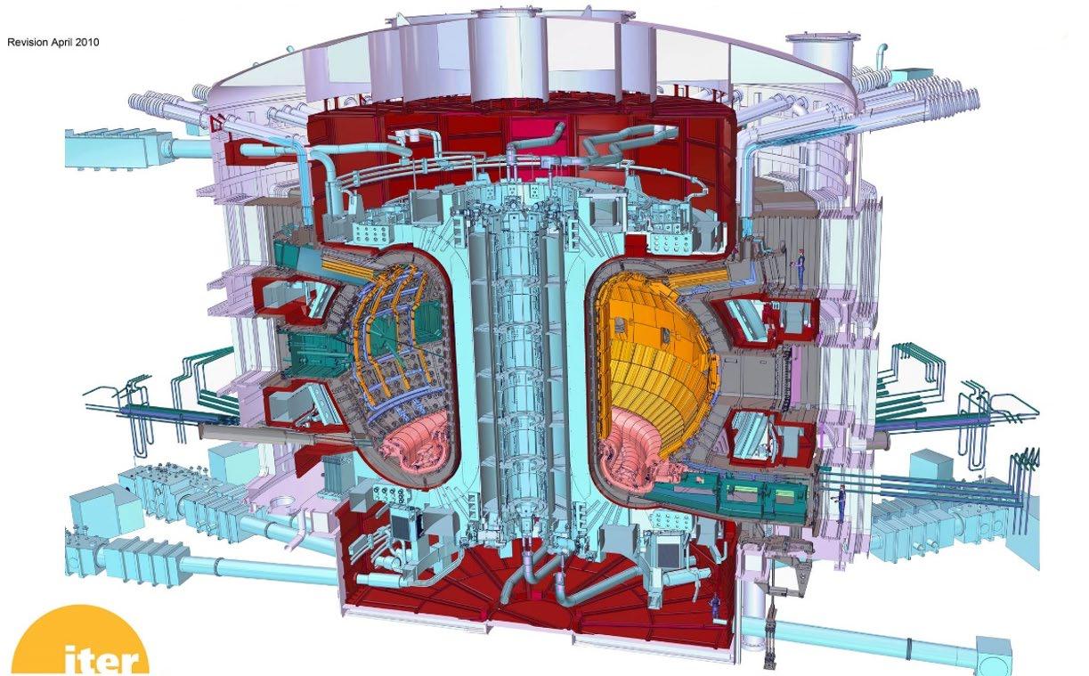

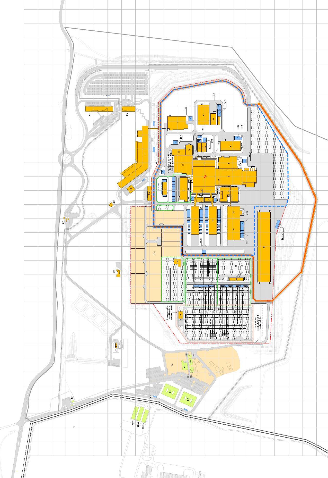
Before site selection, in the FDR of 2001, the Tokamak Complex foundation thickness was defined as 5m, aiming to support the entire Tokamak Complex Building on any type of ground, including soft soil. During the Site Selection process, since both Rokkasho and Cadarache sites were in earthquake-prone locations, the concept was developed of splitting the foundations into two "basemats" (i.e. structurally integrated load-spreading concrete rafts) separated by concrete plinths on which were mounted antiseismic bearings, aiming to reduce horizontal and vertical seismic accelerations on the building and equipment, decoupling them as far as possible from the Tokamak Machine (see figure).
Once the decision was taken in favour of Cadarache, the experience of building the nearby Jules Horowitz reactor was taken into account (in PCR-059) establishing the lower basemat thickness at 2m and the upper basemat (the "B2 slab") at initially 4m and then 3m in the 2010 Baseline.
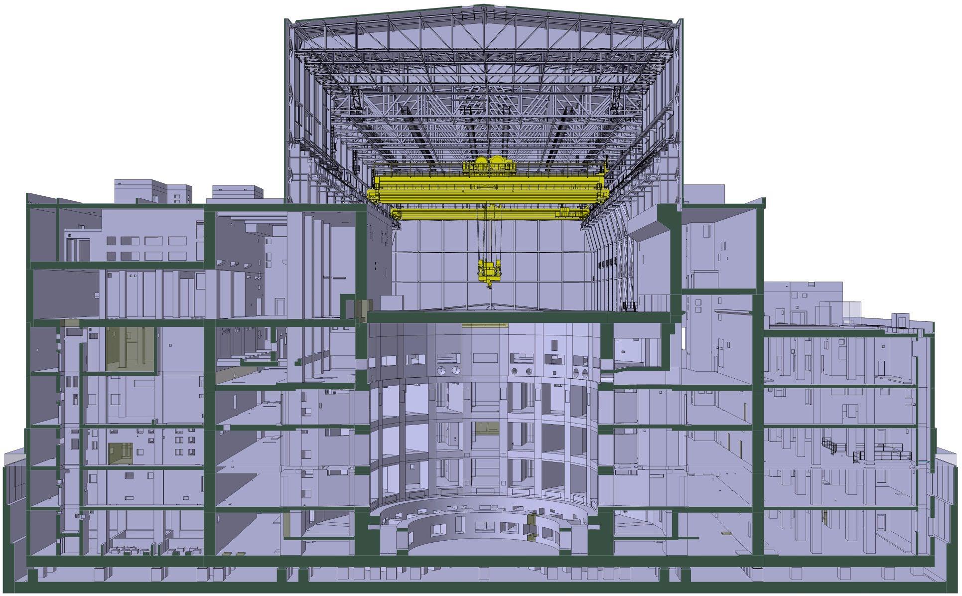
As part of a campaign in 2010 of adjustment of the concrete and steel structures of the Tokamak Complex Buildings (including wall thicknesses where the nuclear shielding requirements allowed) (resulting in PCR 283), the B2 slab thickness was reduced to 1.5m. Simultaneously, , the thickness of the lower basemat was reduced from 2 to 1.5m (PCR 285).
These changes provided obvious schedule and cost advantages but were sources of continuing challenging discussions with the Nuclear Safety Authority (ASN) since the Preliminary Safety Report of 2010 quoted a larger thickness. The development and the justification of the B2 slab design was then carried out including safety margin provisions (providing resilience to a post-Fukushima seismic event), Tokamak Machine load combinations, and an enhanced Tokamak Support Structure.
Although these changes led to significant reductions in the potential horizontal accelerations experienced by Tokamak Complex equipment, accelerations in many cases remained large, particularly on higher floors, requiring additional compensating design features.
In 2016, the IO and the DAs developed an updated strategy with the objective of securing a first plasma by the end of 2025 (see Figure 7.1.10 1).
Considering the budgetary constraints and the actual status of the procurement, this approach focussed on the realization of the core elements needed for the First Plasma, which would mark the completion of the key assembly and commissioning phases of the Tokamak and support facilities.
The First Plasma operation phase (FP) would serve mainly to demonstrate the performance of the core systems.
The determination of the Toroidal Field magnetic axis was also considered in the staged approach baseline. That diagnostic would be done at the end of the First Plasma operation phase. A PCR was already raised to include the associated diagnostic means and the measurement phase in the 2016 baseline considering afterwards the customization of some of the blanket shield modules during Assembly phase II to cope with the input data from the magnetic axis determination.
Soon after, the machine would be re-opened for the installation (Assembly phase II) of the additional systems needed for the first non-nuclear operation phase (Pre Fusion Power Operation 1, PFPO-1) especially all in-vessel components, additional heating and diagnostic systems required for that phase. Then, at its completion, the construction work would be restarted (Assembly phase III) to complete the installation of the components needed for the nuclear phase, such as additional heating systems, diagnostics and test blanket modules).
These would be commissioned in the next operation phase (Pre Fusion Power Operation-2, PFPO2) and any necessary changes implemented in Assembly phase IV, followed by integrated commissioning and operation first in DD, and then in DT.
7.1.10.1 Draft Outline Plan for the Staged Approach (milestones proposed in 2016)
Thus, in the new baseline, there would be different successive physical configurations of the machine, each one of them adapted to the specific goals of each phase and compliant with plasma physics functional requirements and Nuclear Safety requirements.
Following the endorsement of this strategy by the ITER Council in June 2016, the IO and DAs worked together to develop a detailed list of the elements of the ITER plant essential to achieve the objectives of each stage in order to prioritize the procurement activities.
For each of the configurations it was decided to identify in “staged configuration tables”:
1. the essential permanent items required to achieve the objectives of the relevant stage and that were also part of all successive configurations.
2. the temporary items required to achieve the functional or safety requirement of each stage but that had to be replaced or removed in following configurations.
3. the items that were not required for a specific function at a given stage but that may have to be installed in advance to follow the logic of the construction process, so called “captive components”, should their procurement occur earlier.
Changes in the baseline thus affected mainly the project cost and schedule. However, some technical changes and the need to procure additional temporary items were found to be a consequence of the staged approach. In addition, the new baseline included the changes related to the implementation of the stress test results to deal with extremely unlikely events (the "postFukushima" approach) that in the case of ITER consisted mainly in designing (or just verifying) the effectiveness of the last confinement barriers against extreme earthquakes.
It was recognized that while postponing the delivery of part of the plant could benefit the expenditure profile of each party, it could result in an overall cost increase as some production lines could need to be kept active for a longer period and because additional provision might be needed to allow operation. This was the case, for instance, in the procurement of temporary closure plates to establish the vacuum boundary at locations where the final port plugs were not delivered.
There were no changes to the technical objectives at this point, although the delineation of the operational stages had a definitive impact on the functionality of ITER and the timing and capability of the testing it would carry out.
Potential changes identified through the staged approach
Staged approach configurations were exhaustively defined and described in PCR-738. (Thirteen potential daughter PCRs were identified at that time and some of them were proposed for implementation in the 2016 baseline when supported by the parent PCR-738.)
Beryllium storage: As the hot cell would not be available until 2028, a temporary facility would be required to deal with beryllium first wall panel acceptance tests, trial fitting and storage.
ICRH: The IC decision to have 10MW available for PFPO-1 meant accelerating the ICH transmission line and antenna design and procurement.
Low field H-mode: The decision to undertake some operation in H-mode at 1.8T during PFPO-1 required accelerating the ELM mitigation coil power supplies procurement and analysis of any filtering needed to minimise the influence of stray radiation, as well as an analysis of the ability of the diagnostics to work at that field.
Heating NB 3: To avoid installation by reopening the NB cell in the pre-nuclear phase, early procurement and installation of the HNB3 captive components would be necessary, as well as coordination with other installations in the NB cell such as winding of VS coils.
Vertical stability 1 convertor: would need upgrade before second plasma.
Divertor: the divertor at the start of operation would have a tungsten first wall.
B71: Physical segregation of plant Protection Important Component PIC/non-PIC parts to allow procurement and installation of only non-PIC subsystems & components for the first plasma phase.
Control building: Temporary building would be needed due to the delay of the construction of the final Control Building that may not be ready for first plasma phase.
Vacuum vessel: A rupture disk on port 6 would be provided if a risk were identified and if it were absolutely needed to cover an overpressure to protect the Vacuum Vessel PIC component in case of a LOCA in the VV that could apparently occur during the baking mode of the VV at 200°C.
Vacuum vessel protection system: SS panels would be attached to vacuum vessel during first plasma as temporary inertial cooling first wall.
Sealing flange procurement: If not procured by Korea, the IO would purchase blank flanges for port plugs not installed by first plasma.
Connection to Chilled Water System CHWS-H1: Piping would be already captive at Assembly phase 1 prior to FP phase. Although not required to be SIC by FP, if necessary local air coolers in SIC cubicle rooms could be cooled by a temporary connection to CHWS-H2 non-SIC system at each level of the galleries. That would allow to defer CHWS-H1 until it was needed in the nuclear phase.
Baking of ECH upper plugs and diagnostic plugs: Needed for FP phase. Would make use of the already available Air-Drying System for FP (in nitrogen gas phase) via the in-vessel IBED PHTS captive piping installed for FP inside the cryostat and port cells.
Additional Design Changes from 2010 up to 2016 baseline
Additional changes introduced in this baseline were those related to the refinement of the design, for instance to account for the increased maturity level of the major plant systems or those related to the clearance of the hold points placed by French Nuclear Safety Authorities requiring a full justification of the design with respect to loading conditions including load combinations.
These included the following points.
• Modification of the tokamak basic machine support system, with the addition of a reinforced concrete crown connected to the bioshield through 18 radial walls to improve the transfer of the tokamak loads and their distribution between the B2 slab and the bioshield through 18 additional cryostat support bearings (2012-2014). Refinement of the design of the B2 slab to improve its robustness and integrity as part of the last confinement barrier.
• Assessment and justification of the NB cell integrity that is also part of the last confinement barrier, including the cancellation of all tokamak north wall penetrations to increase the robustness of the tokamak last confinement barrier (part of the postFukushima approach).
• Reinforcement of process rooms and associated HVAC systems in the tritium building that are at risk of facing a deflagration.
• Addition of radiation shielding walls in the 4 corners of the tokamak galleries (all levels) to improve the protection of systems cubicles electronic equipment together with the reinforcement of port cells doors shielding efficiency against fast neutrons for the same purpose.
• Modification of the Tokamak Cooling Water System (TCWS) configuration due to the 16N & 17N radiation issue and to deal with skyshine: the heat exchangers, pumps and motors were moved from the L4 vault annex to the L3 vault.
• Linked to the above 16N/17N issue, change from normal concrete to heavy concrete (HC) or heavy borated concrete (HBC) in the vault area to limit radiation to galleries: HC was implemented in lower pipe chase walls (B2 level) and HBC implemented for slabs and walls of the upper pipe chase (L3-L4 levels) to meet radiation zoning requirements for nuclear buildings defined in the RPrS 2010 baseline.
• Vacuum Vessel Pressure Suppression System (VVPSS) modification by eliminating the huge tank located at L5 not compliant in terms of anchorage to the building in case of a seismic event. Use of part of the drain tank room located underground below the tokamak at B2 level to locate two new VVPSS tanks. Consequently, two of the four main drain tanks were transferred from tokamak complex to the hot cell complex (HCC).
• Management of the risk of overpressure inside the cryostat in case of a helium pipe break during a seismic event: adding rupture disks to the cryostat wall at the B2 level connected to the tokamak gallery together with relief panels in the gallery at the L3 level. The release of helium gas to the vault annex is to avoid any risk of exceeding design overpressure in tokamak galleries that define the last confinement barrier.
• Same approach as above, modification to protect galleries from an overpressure in case of a break of highly pressurized water-cooling process pipes of the TCWS (i.e. vacuum vessel, blanket, divertor, in-vessel coils,) when crossing the gallery or routed from vault to inside the cryostat: change concerns the adding of stainless-steel guard pipes surrounding process pipes. Consequently, in line with RPrS requirement a break of a TCWS pipe through an accident identified as a loss of coolant (LOCA) will not challenge the integrity of the galleries. From a design point of view, a LOCA and consequent overpressure (if any) is contained in the vault.
• The maturity of the plant systems implemented in the tokamak complex through the 2010 baseline was limited for many of them. A progressive finalization of the interfaces between systems and B11, B14, B74 buildings (level by level from B2 up to L5) was required to freeze temporary openings, plant system penetrations, embedded plate size & location, gravity loads and other loading conditions such as reaction forces of systems supports to the buildings walls & slabs. The issue of the detailed construction design at Manufacturing Readiness Review stage was organized level by level from 2013 up to 2017. It was managed in a successful way through the setting up of an IO-F4E Building Integration Task Force (BITF) on site and an appropriate full control of the tokamak complex buildings configuration involving all stakeholders through a very tight building construction schedule.
• Modifications of the non-nuclear diagnostic building from what was implemented in the 2010 baseline related to its lack of protection against aeroplane crash (APC). An initial deviation request (DR#2) was raised and approved in 2012 to protect the SIC rooms hosting SIC cubicles in the diagnostic building B74: the rooms up to the upper L3 level were reinforced accordingly. A further analysis of the systems installed in B74 demonstrated at the end of 2016 that some of the busbar penetrations implemented from diagnostic B74 to tokamak B11 magnet feeders at upper L3 level would probably not keep their integrity with respect to being the last confinement barrier in case of an APC, inducing also a risk of a fire propagation in the tokamak gallery. Therefore, a deviation request (DR#12) was raised and approved in 2016 to reinforce the L2, L3 levels of the B74 walls and roof against a risk of collapse in case of an APC.
In 2022, the ITER Project was confronted with important challenges and delays deriving from the COVID pandemic, the international political situation, and the dimensional defects detected on the first vacuum vessel and thermal shield deliveries for this first-of-a-kind industrial-scale DT fusion device. The DG, noting the impossibility to achieve a First Plasma in 2025, turned the delay into an opportunity and introduced a number of design changes that would accelerate the achievement of the nuclear phase while minimising a series of project risks, including the risk linked with the uncertainties in the licensing process.
The strategic elements of the ITER 2024 Baseline are detailed below.
• The adoption of a stepwise safety demonstration and licensing approach, with an initial DT phase (DT1) where the neutron fluence authorized is limited to ~1% of the total endof-life neutron budget. DT1 encompasses five fusion power operation (FPO) campaigns.
• The incorporation of lessons learnt regarding manufacturing, repair and assembly, and including the corresponding DAs re-planning of in-kind deliveries.
• The replacement of the previous First Plasma phase - envisioned as a brief, low-energy machine test - with a longer more scientifically and technically meaningful first operation phase (start of research operations, SRO), by anticipating as much as possible the installation of most of the in-vessel components and taking advantage of passive cooling.
• The valuable testing of novel components, such as for some of the TF coils in a Magnet Cold Test Facility, before assembly and commissioning.
• The minimization of delays to achieving important mission goals, such as demonstrating an integrated fusion engineering system (including full magnetic current operation), and achieving the fusion energy gain of Q≥10 with 500MW of fusion power.
• The optimization of systems based on updated scientific and technological knowledge, especially when relevant for future reactor designs, such as by changing the first wall armour material from beryllium to tungsten, increasing plasma heating power, etc.
• The identification of the critical risks for the Project Baseline, and correspondingly reassessing and incorporating contingency for schedule and cost.
From the schedule viewpoint, the ITER 2024 Baseline retains the concept of a staged approach of the ITER 2016 Baseline but adapts it to the new delivery dates agreed with the DAs, to the expected durations of the assembly activities, and especially to the new research plan that requires most of the in-vessel components to be installed from the first operation campaigns (see Figure 7.1.11 1)
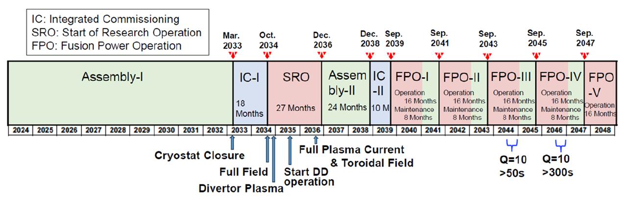
There were no changes to the technical objectives at this point.
From the design standpoint, the evolution of ITER in this phase is driven by the change of the first wall armour material from beryllium to tungsten. The main components such as the vacuum vessel (in advanced manufacturing status) or the magnets (all of them already delivered) do not undergo a design revision. In fact, the design changes in the ITER 2024 Baseline are rather limited in scope given the advanced status of the project with the DAs having already completed ~65% of their in-kind responsibilities.
First Wall: the first wall armour is redesigned in tungsten for innumerable reasons that span from providing it with longer lifetime and increased resilience to transient loads to the possibility of outsourcing the treatment of the downstream waste (now free of beryllium). Relevant also is the simplification in the licensing case, which was imposing very strict requirements for all exposed components to beryllium, including very strict beryllium zoning throughout the ITER facility and during its life cycle.
Remote maintenance: The plan to deploy an in-vessel rail system to carry out blanket module maintenance is now replaced by the plan to use a more rapidly deployable boom system for the likely more frequent first wall replacement and individual blanket module replacement if required. The rail system is then retained as a possible backup solution should more extensive blanket replacement be required.
Wall conditioning: Linked with the suppression of beryllium in the first wall and the adoption of tungsten instead, a boronization system is introduced, operating via the decomposition of diborane gas assisted by plasma, i.e. assisted by glow-discharge cleaning with additional
electrodes in the port plugs. Specific plasma wall conditioning pulses and ion cyclotron wall conditioning operation is envisaged. This obviates the need for the system of gas baking of divertor cassettes at 350°C.
Heating and Current Drive: H&CD capability is increased to 103MW (60 MW, 170 GHz EC, 10 MW, 44-55MHz IC and 33MW, 800keV-1MeV NB) compared to 73MW from 2001 to the ITER 2016 Baseline. The increased power levels are required to support plasma scenario development to high current with low fluence (either DD or D with low T-content plasmas) and to allow for substantial radiative power fractions in the core plasma.
Site Layout: The increased capacity in heating and current drive requires several modifications of the site layout (Figure 0: the IC sources and power supplies need to be displaced from Building 15 to a new building at the south of the tokamak (B20) to leave space for new gyrotrons and power supplies required for SRO. This not being enough for DT1, an additional building for EC needs to be erected (B18) together with the connecting bridges to the tokamak complex and all required services such as additional cooling water (B63), load centres, etc.
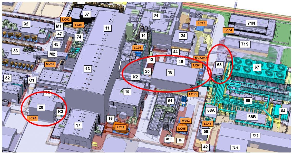
Despite relatively minor changes in its objectives, the design of ITER has evolved considerably in the 37 years since its inception, and it retains its original aim to try to bridge the gap in know-how between the promising plasma physics results of the JET class of experiments, and a potential electric-power-producing demonstration plant. While initially aimed at achieving ignition, the uncertainty of the large extrapolation required has led in time to the more cautious adoption of the aim of high Q operation, where the scientific case to ensure its achievement can be more easily made.
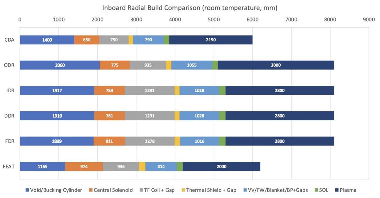
This has led to an excursion in machine dimensions, as illustrated in Figure 0 1 which seems, in the initial 13 years of the design, to have gone full circle. That would be somewhat misleading, as a great deal of design evolution and quite radical change has occurred during that time, in particular:
Magnets: Earlier versions of the ITER design incorporated toroidal field coils bucking on a cylinder inside of which the central solenoid was located. This later became toroidal field coils bucking directly on the central solenoid. Finally, a structural optimum was adopted with toroidal field coils wedged together forming a keystone arch inside which the central solenoid could be freely located. There was an early decision to aim for the maximum fields then possible for superconductors by using Nb3Sn for the central solenoid and toroidal field coils, forcing manufacture by wind, react and transfer, and the use of radial plates for added strength in the TF coils. For the other poloidal field coils the flexible NbTi superconductor would be sufficient.
Plasma-facing components: The initial decision was to use carbon due to its high heat resistance and low atomic weight and thus low plasma-impurity-radiation-inducing potential. Beryllium was even superior in this aspect and experimental results on existing machines were promising. However, increasingly, concerns arose about carbon dust and its ability to trap tritium, which would raise in-vessel inventories, and working with beryllium due to the toxicity of its dust, as well as its lack of high heat load tolerance. In the meantime, extensive experiments have been carried out using tungsten, demonstrating that despite its high atomic weight, the impurity radiation from the plasma can be controlled, and this has led to the decision to use solely tungsten in the 2024 baseline.
Blanket/first wall: Initial designs combined these into a single component, and various mounting schemes were adopted to accommodate weight and disruption forces. The first consisted of separate back plates with a number of modules attached, each unit being able to be removed vertically through the upper vessel ports for maintenance. The next iteration combined the back plate to give more toroidal strength and support during plasma disruptions, leading to modules having to be remotely replaced via a number of equatorial ports. Disruptions were still a concern, and front-mounted modules required the design evolution of specialized attachments as well as internal cooling pipe cutting and welding. Heat loads on the first wall were kept low by initially using a ring of more specialized belt limiter modules as protection. Later these were replaced by port-mounted limiters which were easier to replace. Following the design review in 2007 the first wall heat rating requirement was raised and the limiter concept abandoned, and the concept of separating blanket and first wall was introduced, with the first wall being more easily removable by in-vessel remote maintenance, with a more extensive set of less time-critical remote operations needed if a blanket module needed replacement. The choice of method of blanket remote maintenance (i.e. boom or rail) is still to be decided.
Divertor: After an initial flirtation in the CDA with divertor plates maintained from an in-vessel rail mounted manipulator, the design switched to cassettes mounted on toroidal rails and withdrawn radially through lower ports, initially on radial rails, and later with a cantilevered manipulator.
Vacuum vessel: Single-walled in the CDA, but double-walled from the start of the EDA, with the vessel being able to exhaust residual heat from neutron activation passively by natural convection should there be a complete loss of vessel and in-vessel active cooling. In the final ITER design after the backplate removal, the vessel also has to support the blanket/first wall modules. Initially the vessel was supported from the magnet structure, but was subsequently separately supported with radially flexible supports.
Heating: The preferred combination of heating systems has fluctuated as the physics results have come in over the years. The CDA favoured NB:75MW/LH:50MW/EC:20MW for a total of 145MW. It was subsequently considered that this could be reduced to IC:50MW at the start of the EDA due to the much larger plasma, and this amount later was spread over other heating systems in various combinations, always with the possibility of upgrade to 100MW if needed. For the final design the
initial proposal was for 73MW, but this was raised to 103MW in 2024, with the currently favoured combination being NB:33MW/IC:10MW/EC:60MW.
Blanket testing: The CDA foresaw tritium breeding during the second 10 years of operation, supplying 80-90% of the tritium consumed. This aim was dropped as an essential at the start of the EDA, and replaced by a plan for a considerable programme of blanket testing, based on external supplies of tritium, and using four equatorial ports for blanket testing. The concept of installing a driver blanket to supply some tritium was however maintained for the EDA, but only finally dropped for the EDA extension leading up to the 2001 design. Since then, the number of ports available for blanket testing has fallen to two. The gradual erosion of the objective to carry out tritium-breeding blanket testing/qualification on ITER, given that the economics of using ITER for that purpose has turned out to be questionable, means that ITER blanket testing is now unlikely to fully qualify the tritium self-sufficiency needed in a demonstration plant.
In engineering, the devil as ever is in the detail, and the considerable efforts of the ITER participants' scientists and engineers in design, hardware testing and development over the years have forced the acceptance of certain designs and the rejection of others and have sometimes led to the abandoning or introduction of more ambitious solutions with apparently more reactor relevance. The decision to proceed with construction has led to a focus on solutions which will work now, even if that means later developments may be more protracted.
ADS Atmosphere detritiation system
APC Airplane crash
ASN French nuclear authorities
BITF Building Integration Task Force
BPP Basic Performance Phase
BSM Blanket shield module
CDA
CFC
Conceptual Design Activities
Carbon-fibre composite
CHWS Chilled Water System
CICC
Cable-in-conduit conductor
CS Central Solenoid
DA Domestic agency
DCR
Design change request
DDR Detailed design Report
DMS
DNB
DT1
Disruption Mitigation System
Diagnostic Neutral beam
The first phase of active operation (mostly DD)
EC Electron cyclotron
EDA
ELM
EPP
Engineering Design Activities
Edge-localised mode
Enhanced Performance Phase
FDR Final Design Report
FW First wall
FP First plasma
HAM
High aspect ratio machine
H&CD Heating and Current Drive
HBC Heavy borated concrete
HC Heavy concrete
HVAC
Heating, ventilation and air conditioning
IAM Intermediate aspect ratio machine
IBED In-vessel Blanket, ELM coils, Divertor cooling loop
IC Ion cyclotron, ITER Council
IDR Interim Design Report
IO ITER Organization
ITPA ITER Tokamak Physics Activity
LAM Low aspect ratio machine
LH Lower hybrid
LOCA Loss of coolant accident
NB Neutral Beam
NBI Neutral Beam Injector
ODR Outline Design Report
PCR Project Change Request
PHTS Pressurized (water) heat transfer system
PFPO Pre Fusion Power Operation
PIC Protection Important Component (from nuclear safety point of view)
RF Radiofrequency
RH remote handling, resonance heating
RPrS Preliminary safety report (Rapport preliminaire de surete)
RTO/RC Reduced technical objectives/reduced cost
SIC Safety importance class(ified)
SRO Start of Research Operations
TAC (ITER) Technical Advisory Committee
TBM Test Blanket Module
TCWS Tokamak cooling water system
TMP Turbomolecular Pump
TS Thermal shield
VDE Vertical displacement event
VDS Venting and Detritiation system
VV Vacuum vessel
VVPSS
Vacuum vessel pressure suppression system
[1] ITER Documentation Series No. 1,” IAEA, 1988, pp. 40–
[2] K. Tomabechi, “ITER: Conceptual Design,” IAEA, Rep. IAEA-CN-53/F-I-1, 1991
[3] E. Salpietro, “ITER: Engineering Basis,” IAEA, Rep. IAEA-CN-53/F-I-4, 1991
[4] J. R. Miller et al., “ITER Superconducting Magnet System,” IAEA, Rep. IAEA-CN-53/F-III-7, 1991.
[5] “ITER Tokamak Device,” ITER Documentation Series, no. 25, IAEA, 1991
[6] C. A. Flanagan, “ITER Plant System and Site Requirements,” IAEA, Rep. IAEA-CN-53/F-III-14, 1991
[7] L. Bottura et al., “ITER Transient Electromagnetics,” IAEA, Rep. IAEA-CN-53/F-III-10, 1991
[8] D. Smith et al., “ITER Tritium Breeding Blanket,” IAEA, Rep. IAEA-CN-53/F-III-11, 1991
[9] P. Dinner, “ITER Fuel Cycle Design,” IAEA, Rep. IAEA-CN-53/F-III-13, 1991.
[10] W. M. Nevins et al., “ITER Current Drive and Heating Physics,” IAEA, Rep. IAEA-CN-53/F-III-4, 1991
[11] W. Lindquist et al., “ITER Current Drive and Heating Systems,” IAEA, Rep. IAEA-CN-53/F-III-5, 1991
[12] F. Casci, “ITER Basic Machine Layout,” IAEA, Rep. IAEA-CN-53/F-III-8, 1991
[13] T. Honda et al., “ITER Remote Maintenance,” IAEA, Rep. IAEA-CN-53/F-III-9, 1991
[14] R. Toschi, “ITER Design Overview,” IAEA, Rep. IAEA-CN-53/F-I-2, 1991
[15] “ITER Physics Basis,” Nuclear Fusion, vol. 39, pp. 2138–2664, 1999.
[16] Plasma Physics and Controlled Fusion, vol. 37, no. 11A, 1995
[17] “Interim Design Report Package,” ITER Council Proceedings, IAEA, Vienna, 1995
[18] “DDD Magnet System,” ITER, internal report N 11 DDD 44, June 1998
[19] “DDD Vacuum Vessel,” ITER, internal report G 15 DDD 3, May 1998.
[20] “DDD Shielding Blanket,” ITER, internal report G 16 DDD 2, June 1998
[21] “DDD Divertor,” ITER, internal report G 17 FDR 5, May 1998
[22] “DDD Fuelling and Wall Conditioning System,” ITER, internal report G 18 DDD 7, May 1998
[23] “DDD Wall Conditioning System,” ITER, internal report G 18 DDD 10, May 1998.
[24] “Summary of the ITER Final Design Report,” ITER Documentation Series, no. 22, 2021.
[25] Study of RTO/RC ITER Options p 8.