
Product Catalog Weather radars | Wind lidars | Software systems | Airport weather | Lightning networks and sensors | Soundings | Weather sensors | Weather stations | Professional measurement devices | Road weather | SaaS solutions Weather and Environmental Solutions


In the coming decades, meteorologists will play an increasingly important role in helping governments and industry make informed decisions across a range of sectors.
Aviation Aviation weather and runway management solutions from Vaisala are comprehensive, automated, and scalable to keep airport operations running smoothly no matter what kind of weather or conditions you encounter.
We understand the critical need for accurate situational awareness, and we deliver superior and reliable real-time data so air traffic controllers, pilots, and airport personnel can make informed decisions to keep flights, airports, surrounding areas, and ground operations safe and efficient. Our solutions adhere to FAA, ICAO, and WMO standards, regulations, and recommendations to help you meet compliance requirements.
Observations for a better world Weather and Environment serves weather-dependent markets where accurate, real-time, uninterrupted and reliable weather data is essential to run efficient operations. Our offerings enable customers to monitor the natural environment and support operational decision making under any weather conditions.
Ground transportation Road weather technology is critical for winter and summer road maintenance and the automotive industry and other industries affected by weather. Regardless of the application, accurate data regarding road surface and weather conditions, from snow and ice to wind, sand storms, or flooding, empowers your ground transportation decision making with crucial Vaisala’sinformation.road weather systems, sensors, and solutions monitor roadways for the specific parameters you need to know, so you can act effectively or warn travelers.
3
Maritime Vaisala’s complete offering of scalable maritime weather observation solutions keeps your personnel safe and your operations running smoothly. Easy access to accurate and reliable onshore and offshore weather and environmental observation data ensures maritime personnel and port authorities get the information they need to make critical decisions.
Having data on air quality, coastal weather, and waterways right when you need it reduces costly disruptions and delays in port operations. It allows you to plan ahead and react quickly to changing circumstances.
Defense meteorology Observation applications for land, sea and air to enable better timing, troop safety and readiness, and system performance.
Meteorology As the day-to-day impacts from climate change and extreme weather events continue to grow, Vaisala is innovating and equipping meteorology professionals to better understand, forecast, and explain the phenomena.
Urban and industrial systems
4
Weather and environmental solutions for environmental protection agencies, smart city projects including city departments and private sector customers and industries dependent on weather and environmental data, (e.g. power, mining and building automation). Road Asset Management
Support maintenance decisions in your road network by automatically identifying and assessing assets such as pavement defects, signs, and lane markings condition.
Renewable Renewablesenergy relates to the use of wind, solar and weather sensors, remote sensors (incl. lidars, scanning and nacelle mounted), systems, stations, softwares, and data products connected or not to the energy infrastructure (excl.: SCADA), equipment (excl.: wind turbine, solar panel) or system for pre-project phases (excl.: wind or solar resource assessment), and Operations & Maintenance phases (excl.: power curve, weather and production forecast).

Table of contents WEATHER RADARS WRM200 Weather Radar........................................................................................................... 9 WRK200 Weather Radar........................................................................................................................... ............................12 WRS400 Weather Radar.................................................................................................................................. .............................15 WIND LIDARS WindCube Scan Lidar............................................................................................................................. .....................17 WindCube Ground-based Vertical Profiler Lidar.................................................................................... ..................20 WindCube Offshore Vertical Profiler Lidar...................................................................................................... .................22 SOFTWARE SYSTEMS IRIS Focus Remote Sensing Software..........................................................................................................................................24 MCC201 Weather Transmitter Display.................................................................................................................. 26 NM10 Observation Network Manager.............................................................................................................. 28 AIRPORT WEATHER MDF101 Device Mounting and Powering Frame....................................................................................... ..........32 CDU401 Central Data Unit Rack............................................................................................................................. 34 RME111 Radio Modem Enclosure for Central Site.................................................................................... 36 FOC201 Field Communication Box................................................................................................................... 38 RSI51 Runway Light Setting Interface Unit....................................................................................................... 40 WID511 AviMet Wind Panel Display....................................................................................................................... .......42 WID512 AviMet Data Panel Display.................................................................................................................... ..........44 WID513 AviMet Weather Panel Display.............................................................................................................. 46 RWIS Runway Weather Information System.............................................................................................................. 48 LIGHTNING NETWORKS AND SENSORS LS7002 Total Lightning Sensor................................................................................................................................... 50 TLP Total Lightning Processor.................................................................................................................................... 52 TLD100 and TLD200 Total Lightning Database.................................................................................................. 55 FALLS Server Fault Analysis and Lightning Location System..................................................................... 57 FALLS Client Fault Analysis and Lightning Location System.......................................................... 59 TSS928 Thunderstorm Local Lightning Sensor........................................................................................................ 62 SOUNDINGS AS41 Automatic Sounding Station....................................................................................................................... 64 MW51 Cirrus Sounding System.............................................................................................................................. 66 MW41 Sounding System with DigiCORA Software.................................................................................................. 68 MW41 Sounding System................................................................................................................................ 70 MW32 MARWIN Sounding System................................................................................................................................ 72 RS41-D Radiosonde........................................................................................................................................................... 74 RS41-SG Radiosonde.................................................................................................................................................... 76 RS41-SGM Radiosonde................................................................................................................................................... 78 RS41-SGP Radiosonde............................................................................................................................................... 80 RD41 Dropsonde................................................................................................................................................................. 82 RI41 and RI41-B Ground Check Device............................................................................................................... 84 MWH322 Ground Check Device.......................................................................................................................... 86 SPS311G Sounding Processing Subsystem..................................................................................................................... 89 CG31 Portable Antenna Set............................................................................................................................................... 91 CG32 Vehicle Antenna Set................................................................................................................................................. 93 FB13 Filling Balance.............................................................................................................................................................. 95 5
GA31 GPS Antenna.......................................................................................................................... 96 RM32 Telemetry Antenna................................................................................................................. 98 RT20A Radiotheodolite.......................................................................................................................................... 100 ASAP Sounding Station....................................................................................................................................... ........102 16817 Balloon Nozzle...................................................................................................................................................... .........104 WEATHER SENSORS FD70 Forward Scatter Sensor..................................................................................................................................................... 106 FS11 Visibility Sensor............................................................................................................................................................ 108 FS11P Present Weather Sensor................................................................................................................................ ..........110 LT31 Transmissometer............................................................................................................................................. 112 LM21 Background Luminance Sensor............................................................................................................................ 117 PWD10, PWD12, PWD20, and PWD22 Present Weather and Visibility Sensors................................... ........119 PWD20W Visibility Sensor............................................................................................................................................. ..........123 PWD50 Visibility Sensor.................................................................................................................................................. 125 PWD52 Present Weather Detector............................................................................................................................... 127 DRD11A Rain Detector.................................................................................................................................................................... 129 CL31 Ceilometer......................................................................................................................................................... ....131 CL51 Ceilometer.................................................................................................................................................................... .....133 CL61 Lidar Ceilometer................................................................................................................................................. ......135 CL-VIEW Graphical User Interface............................................................................................................................... ........137 BL View Boundary Layer View Software........................................................................................................................... 139 WMT700 Series WINDCAP Ultrasonic Wind Sensor................................................................................................... 141 PJB480 Power Junction Box............................................................................................................................................. ......143 WA15 Wind Set..................................................................................................................................................................................145 WA25 Wind Set................................................................................................................................................................ .....148 WAC155 Serial Wind Transmitter................................................................................................................................. ..........151 WAT12 Analog Wind Transmitter.. ........153 WM30 Wind Sensor........................................................................................................................................................... .........155 WSP150 Surge Protector................................................................................................................................................................157 WSP152 Surge Protector.............................................................................................................................................. 159 HMP155 HUMICAP Humidity and Temperature Probe............................................................................................. 161 DTR13 and DTR15 Radiation Shields............................................................................................................................. 163 DTR500 Solar Radiation and Precipitation Shields........................................................................................................... ....165 PTB110 BAROCAP Barometer.......................................................................................................................................... 167 PTB210 BAROCAP Digital Barometer................................................................................................. 169 PTB330 BAROCAP Digital Barometer......................................................................................................................... 171 PTB330TS Barometric Pressure Transfer Standard............................................................................................... 173 SPH10 and SPH20 Static Pressure Head Series............................................................................................................ .........176 RG13 and RG13H Rain Gauge............................................................................................................................................... .....178 QMR101 and QMR101M Rain Gauge................................................................................................................................ 180 QMT102, QMT103, and QMT110 Soil/Water Temperature Probes......................................................................... ...182 WEATHER STATIONS AWS810 Automatic Weather Station.......................................................................................................................................184 DMU801 Data Management Unit................................................................................................................................... 186 DMS802 Serial Module.............................................................................................................................................. 190 DMS801 Serial Module............................................................................................................................................................... 192 DMA801 Analog Measurement Module................................................................................................................. 194 DMX801 Modem Carrier Module........................................................................................................................... 196 DME801 Ethernet Switch Module.................................................................................................................................. 198 DMB801 Barometer Module........................................................................................................................................................ 200 6
AWS310 Automatic Weather Station.......................................................................................................................................202 AWS310‑SITE Automatic Weather Station............................................................................................................................ 205 QML201C Data Logger..................................................................................................................................................................207 QMD202 Fixed Display.......................................................................................................... 209 QSP431 Surge Protection Unit............................................................................................ ........................................................211 AWS430 Automatic Weather Station.......................................................................................................................... ............213 MAWS201 HydroMet Automatic Weather Station........................................................................................................ 216 QMP213 Mains Power Supply............................................................................................................................................... ......218 MAWS201M TacMet Tactical Meteorological Observation System................................................................................. 220 AUD111, AUD211, and AUD211M Audio Unit............................................................................................................. ...............222 QMD102M Handheld Terminal..................................................................................................................................... 224 DXL421 Leased Line Modem...................................................................................................................................... 226 DKP204W, DKP203W, and DKP202W Short Pole Masts................................................................................ .................228 DKP206 and DKP210 Tiltable Masts...................................................................................................................... ..................230 DKE110F Guyed Frangible Mast.................................................................................................................................................232 DKE110W/AV Composite Pole Mast......................................................................................................................................... 234 DKE200 Frangible Lattice Mast.................................................................................................................................................236 PROFESSIONAL MEASUREMENT DEVICES AQT530 Air Quality Transmitter................................................................................................................................................238 WXT530 Series Weather Transmitter..................................................................................................................................... 240 WXT532 WINDCAP Ultrasonic Wind Sensor............................................................................................................. ............242 BWS500 Beacon Station................................................................................................................................................. ............244 EGW501 Beacon Edge Gateway....................................................................................................................................... 246 DKT504 Tripod Mast.....................................................................................................................................................................248 PSU501 Power Supply Unit and SOL501/SOL502 Solar Panel 20 W.............................................................................250 ROAD WEATHER RoadDSS Manager 252 RoadDSS Navigator Software......................................................................................................................................... 254 RoadDSS Navigator Runway Weather Forecast...................................................................................................................256 MD30 Mobile Detector.................................................................................................................................................... .............258 Ground Cast Sensor 260 RWS200 Road Weather Station..................................................................................................................................... 262 RWS200 Road Weather Station Enclosures.............................................................................................................. 265 DMU703 Data Management Unit................................................................................................................................... .......268 PMU701 Power Management Unit............................................................................................................................ 271 DRI701 Digital Road Interface.................................................................................................................................... 274 DRS511 Embedded Road and Runway Sensor......................................................................................................... 276 DSC211 Remote Road State Sensor.............................................................................................................................. 278 DSC111 Remote Road Surface State Sensor.................................................................................................................. 280 DST111 Remote Surface Temperature Sensor................................................................................................................ 283 DTS12 Series Temperature Sensors.................................................................................................................................. 285 DSP100 Series Surface Patrol Pavement Temperature Sensor........................................................................................ 287 SAAS SOLUTIONS Thunderstorm Manager 289 Wx Beacon 291 RoadAI 293 Wx Horizon 295 VAISALA SERVICE OFFERING Life cycle services..........................................................................................................................................................................297 Remote Monitoring and Diagnostics for Road Weather Stations....................................................................................305 Remote Monitoring and Diagnostics for Weather Radar................................................................................................... 308 7
Vaisala contact information........................................................................................................................................................311 8
Attenuation Correction
•> 35 dB integrated crosspolarization isolation
Enhanced reflectivity is a signal processing technique that improves the detection capabilities of a dual polarization radar. The technique uses echo power estimation to improve the detectivity of weak signals over a long range.
Dual-polarization
Vaisala Hydrometeor Classification (HydroClass) software makes optimal use of dual-channel measurements to detect the types of scatterers present in the atmosphere, such as rain, hail, snow, graupel, and even non-meteorological targets such as insects, chaff, and sea Theclutter.benefit is improved data quality and more accurate warnings for hazardous weather such as hail.
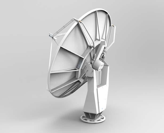
Vaisala Weather Radar WRM200 is a dual-polarization C-band radar that uses a magnetron transmitter.
Attenuation by intervening heavy precipitation has been a long-standing concern with weather radars, especially in tropical environments where heavy rain is Dual-polarizationcommon. radars meet this challenge by performing accurate, real time attenuation corrections.
Enhanced reflectivity
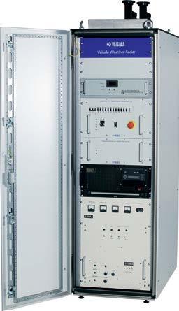
WRM200 Weather Radar Features •250 kW magnetron transmitter with low-maintenance solid-state modulator • Vaisala lightweight, semi-yoke style pedestal •1° beamwidth low side lobe •Modularantenna single cabinet design containing transmitter, receiver, controller, processor, dehydrator, polarization waveguide assembly •Built around RVP900™ and IRIS™ •Remotesoftwarecontrol and monitoring •Image rejection > 80 dB (> 100 dB with Vaisala waveguide filters) •Optional built-in automatic dual channel calibration
Dual-polarization radars send vertically and horizontally polarized microwaves to measure the parameters needed for analyzing the target shape and improving data quality. Targets are identified as, for example, rain, hail, or snow, using sophisticated data processing techniques.
Enhanced reflectivity is exclusive to Vaisala dual-polarization radars and RVP900™
9
Dual-polarization
HydroClass™
•Enhanced reflectivity processing in STAR mode
•Precision horizontal and vertical beam matching
Transmitter specifications
Clutter filters IIR, fixed, and adaptive width GMAP 50 dB rejection Data outputs (8 and 16 bit) Ah/v, Azdr, CCOR, CSP, CSR, dBT, dBZ, dBZt, KDP, LDR, LOG, PHIH/V, PHIDP, PMI, R, RHOHV, SNR, SQI, T, V, VC, W, Z, ZC, ZDR,ZDRC,Zh, Zv, Zhv Dual PRF velocity de aliasing 2:3, 3:4, or 4:5 for 2X, 3X, or 4X de-aliasing
1)Includes cabinet cooler power consumption. 2) Ambient temperature +22 °C, RH 50 %. Options
High sensitivity Zhv STAR 3 dB improvement detection gain IF digitizing 16 bits, 100 MHz in 5 channels Number of range binsUp to 8168 per channel
Optional data outputs HCLASS, I/Q Processing modesPPP, FFT/DFT, Random Phase 2nd trip filtering/ recovery Range resolutionN*22 m Range de-aliasing by random phase System specifications
Technical Data
Transmitter tube Coaxial magnetron VMC-2033A Modulator type Solid-state, utilizing IGBT technology Frequency range 5.5 ... 5.7 GHz
Type Center-fed parabolic reflector Reflector diameter 4.5 m Gain (typical) 45 dB Beam width < 1.0° Difference between H and V beam widths < 0.1° (<0.2 dB difference in gain)
Total weight (4.5 m antenna and pedestal) 1530 kg Antenna specifications
Peak power 250 kW Pulse widths 0.5, 0.8, 1.0, or 2.0 μs. Duty cycle 0.12 % Phase stability < 0.5° rms Pulse Repetition Frequency 50 ... 2400 Hz Average Power 300 W, 0.0012 duty cycle Modes STAR or LDR Dimensions (W × H × D) 483 × 622 × 920 mm Weight 76 kg (typical configuration)
Antenna and pedestal mechanical specifications
Acceleration 20 degrees/second2 Position accuracy < 0.1° Motors Brushless AC servo Weight 910 kg Signal processing Signal processorVaisala RVP900 Azimuth averaging2 ... 1024 pulses
Type Semi-yoke elevation over azimuth Angle span software limits -2 ... 108° Maximum scan rate (azimuth and elevation) 40 degrees/second (6.67 rpm)
Input power Voltage: 3-phase 230/400 VAC ± 10 % 50-60 Hz ± 5 % Site mains supply fuses: min 16 A Pedestal Max. 1050 W Typical 200 W Radar cabinet1) Max. 2500 W Typical 2000 W 2) Phase stability < 0.5° rms Maximum RhoHV> 0.99
Radome Typical 6.7 m, foam core sandwich, random panel Automatic calibration Forward and reverse transmitted power monitoring Wide dynamic range receiver > 115 dB 10
Peak sidelobes at main polarization planes < -29 dB Integrated cross-pol isolation < -35 dB Cross-pol isolation at main polarization planes < -36 dB H/V alignment (squint angle) < 0.1° Weight (reflector with counterweight plate) 620 kg Pedestal specifications
1)The
filters
1st intermediate
receiver specifications
2nd intermediate frequency 60 MHz Radar controller specifications Type Vaisala RCP8 with IRIS Radar Scan modes PPI, RHI, Volume, Sector, Manual, Rapid Scan Local display Real time, Ascope, BITE, products Radar cabinet specifications Dimensions
www.vaisala.com 11
dual-channel IF downconverter and digitizer Noise
Radar
Image rejection
Type Dual-stage, figure < 2 dB Dynamic range > 99 dB (2 μs pulse) (option > 115 dB) > 80 dB > 100 dB with waveguide Tuning range 5.5 ... 5.7 GHz frequency 442 MHz (W × H × D)600 × 1800 × 1320 mm Total height 1890 mm1) Weight 380 kg Cooling Air-conditioned Operating temperature+10 ... + 40 °C Recommended operating temperature +15 ... + 25 °C Operating humidity0 ... 95 %RH, non-condensing Storage temperature−50 ... +50 °C Operating altitude/ Ambient pressure Up to 3000 m Up to 700 hPA total height includes the cabinet protection unit and cabinet legs.
Vaisala Hydrometeor Classification (HydroClass) software makes optimal use of dual-channel measurements to detect the types of scatterers present in the atmosphere, such as rain, hail, snow, graupel, and even non-meteorological targets such as insects, chaff, and sea Theclutter.benefit is improved data quality and more accurate warnings for hazardous weather such as hail.
Dual-polarization
WRK200 Weather Radar Features •250 kW klystron transmitter with low-maintenance solid-state •Vaisalamodulatorlightweight, semi-yoke style pedestal •1° beamwidth low side lobe •Feedantennaforward control loop to allow extremely fast and precise antenna movement •Built around RVP900™ and IRIS™ •Remotesoftwarecontrol and monitoring •Image rejection > 80 dB (> 100 dB with Vaisala waveguide filters) •Dynamic range > 99 dB (2 μs •Optionalpulse) built-in automatic dual channel calibration
send vertically and horizontally polarized microwaves to measure the parameters needed for analyzing the target shape and improving data quality. Targets are identified as, for example, rain, hail, or snow, using sophisticated data processing techniques. Enhanced reflectivity Enhanced reflectivity is a signal processing technique that improves the detection capabilities of a dual polarization radar. The technique uses echo power estimation to improve the detectivity of weak signals over a long range.
Enhanced reflectivity is exclusive to Vaisala dual-polarization radars and RVP900™ HydroClass™
•> 35 dB integrated crosspolarization isolation
•Enhanced reflectivity processing in STAR Dual-polarizationmoderadars
•Precision horizontal and vertical beam matching
Vaisala Weather Radar WRK200 is a dual-polarization C-band radar that uses a coherent klystron transmitter
Attenuation Correction Attenuation by intervening heavy precipitation has been a long-standing concern with weather radars, especially in tropical environments where heavy rain is Dual-polarizationcommon. radars meet this challenge by performing accurate, real time attenuation corrections.
12
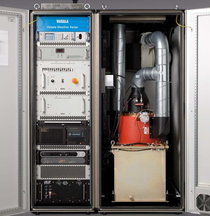
Type Semi-yoke elevation over azimuth Angle span software limits -2 ... 108° Maximum scan rate (azimuth and elevation) 40 degrees/second (6.67 rpm)
Pulse widths Typical 0.5, 0.8, 1.0, 2.0, max. 5.0 μs Pulse repetition frequency 250 ... 2125 Hz Modulator Solid state Phase stability <0.1 degrms
Antenna and pedestal mechanical specifications
Optional data outputs HCLASS, I/Q Processing modesPPP, FFT/DFT, Random Phase 2nd trip filtering/ recovery Range resolutionN*22 m Range de-aliasing by random phase
Transmitter tube Klystron VKC8387 Frequency range 5.6 ... 5.65 GHz Peak power 250 kW Average power max. 550 W Duty cycle 0.0022
Total weight (4.5 m antenna and pedestal) 1530 kg
Clutter filters IIR, fixed, and adaptive width GMAP 50 dB rejection Data outputs (8 and 16 bit) Ah/v, Azdr, CCOR, CSP, CSR, dBT, dBZ, dBZt, KDP, LDR, LOG, PHIH/V, PHIDP, PMI, R, RHOHV, SNR, SQI, T, V, VC, W, Z, ZC, ZDR,ZDRC,Zh, Zv, Zhv Dual PRF velocity de aliasing 2:3, 3:4, or 4:5 for 2X, 3X, or 4X de-aliasing
High sensitivity Zhv STAR processingmode > 3 dB improvement detection gain IF digitizing 16 bits, 100 MHz in 5 channels
Radome Typical 6.7 m, foam core sandwich, random panel Automatic calibration Forward and reverse transmitted power monitoring Wide dynamic range receiver > 115 dB 13
Antenna specifications Type Center-fed parabolic reflector Reflector diameter 4.5 m Gain (typical) 45 dB Beam width < 1.0° Difference between H and V beam widths < 0.1° (<0.2 dB difference in gain)
Technical Data Klystron transmitter specifications
Peak sidelobes at main polarization planes < -29 dB Integrated cross-pol isolation < -35 dB Cross-pol isolation at main polarization planes < -36 dB H/V alignment (squint angle) < 0.1° Weight (reflector with counterweight plate) 620 kg Pedestal specifications
Acceleration 20 degrees/second2 Position accuracy < 0.1° Motors Brushless AC servo Weight 910 kg Signal processing Signal processorVaisala RVP900 Azimuth averaging2 ... 1024 pulses
Number of range binsUp to 8168 per channel
System specifications Input power Voltage: 3-phase 230/400 VAC ±10 % 50- 60 Hz ± 5 Site% mains supply fuses: min 25 A Pedestal 1050 W (max.) / 200 W (typical) Radar cabinet Max. 8720 W with UPS Max. 7850 without UPS Phase stability < 0.1° rms Maximum RhoHV> 0.99 Options
Noise figure < 2 dB Dynamic range > 99 dB (2 μs pulse) (option > 115 dB) Image rejection > 80 dB > 100 dB with waveguide filters
Tuning range 5.5 ... 5.7 GHz
Type Vaisala RCP8 with IRIS Radar Scan modes PPI, RHI, Volume, Sector, Manual, Rapid Scan Local display Real time, Ascope, BITE, products
1)The total height includes the cabinet protection unit and cabinet legs. www.vaisala.com
14
Radar receiver specifications
Type Dual-stage, dual-channel IF downconverter and digitizer
Dimensions (w × h × d)1400 × 1800 × 1300 mm Total height 1890 mm1) Weight 977 kg Cooling Equipment rack: air-conditioned Transmitter: forced air Operating temperature+5 ... +40 °C +15 ... +25 °C recommended Operating humidity0 ... 95 %RH, non-condensing Storage temperature−50...+50 °C without oil −10 ... +50 °C with oil Operating altitude/ Ambient pressure Up to 3000 m Up to 700 hPA
1st intermediate frequency 442 MHz 2nd intermediate frequency 60 MHz Radar controller specifications
Radar cabinet specifications
By filling gaps in radar networks, the X band weather radar improves radar network coverage, for example, in mountainous areas, rain catchment areas, and around wind parks.
Solid-state power amplifier (SSPA) transmitters provide increased observation accuracy, sensitivity, and tracking quality. The ultra-wideband performance virtually removes the risk of frequency interference.
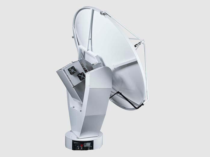
Vaisala Weather Radar WRS400 is a dual polarization X-band radar that uses solid state transmitters.
The life-cycle costs of the SSPA transmitters are low because they do not require replacement of expensive consumable parts, in contrast to tube based transmitters. Thanks to continuous calibration, there is no calibration downtime. SSPA transmitter is also smaller in size compared to traditional tube-based models. Improved coverage with high quality X-band frequency provides measurement data with high resolution and excellent precision for short-range meteorological surveillance.
Solid-state transmitters
Compact design The compact weather radar is designed for fast installation and easy Themaintenance.transceiver is located at the back of the antenna, so only a short waveguide structure is needed. The simplified signal path provides improved sensitivity. The simplified structure requires no RF rotary joints, waveguide switches, or site-specific parts. This enables increased data quality, reliability, and lower costs. Because there is no need for a large equipment room, the site construction work is less extensive, and maintenance costs lower.
WRS400 Weather Radar Features •Fully solid-state transmitters •Compact, modular design •High resolution, accuracy, and •Fastsensitivityinstallation and easy •Lowmaintenancelife-cycle costs •Built-in automatic calibration •Graceful •Built•Light-weightdegradationpedestalaroundRVP900™ and IRIS™ software
Graceful degradation WRS400 has an independent SSPA transmitter for H channel and V channel. The radar design is based on reliable and redundant modules; even if one of the key components fails, the system will still maintain limited functionality. The failing component can be replaced fast and easily without an extensive break in operation.
The transceiver has an internal heating/ cooling system. The other units can be installed inside radar cabinet, or in other preferred location.
15
Number of range binsUp to 8168 per channel
Operating environment for units in the radome Operating temperature -40 ... +55 °C Operating humidity 0 ... 100 %RH, condensing Operating altitude/Ambient pressureUp to 3000 m Up to 700 hPA IP class for pedestal and transceiver IP54 Antenna specifications
Typical operating range 100 km Input power Voltage: 230 ±10 %, 50 ... 60 Hz ± 3 Hz (single-phase)
Transmitter specifications
Signal processing Azimuth averaging2 ... 1024 pulses
Reflector diameter 1.4 m or 2.4 m Type Center-fed parabolic reflector Gain (minimum) For 1.4 m antenna: >40 dBi For 2.4 m antenna: 45 dBi Beam width For 1.4 m antenna: <1.8° For 2.4 m antenna: <1°
Type RF front-end, dual-channel digital receiver for horizontal and vertical polarization Noise figure ≤3 dB Linear dynamic range 95 dB or better Image rejection 80 dB or better (with WG filters) Recovery time after Tx pulse ≤5 µs System specifications
1)Measured in a situation representing a typical radar maintenance situation, where the fans are on but the antenna is not rotating.
Property Value Type Quasi-random (dual-polarization)
Total weight of radar (antenna, pedestal, transceiver) With 1.4 m antenna: approx. 340 kg With 2.4 m antenna: approx. 370 kg Storage temperature -50...+60 °C Noise emissions 55 dB 1)
Type Vaisala RCP8 with IRIS Radar Scan modes PPI, RHI, Volume, Sector, Manual, Rapid Scan Local display Real time, Ascope, BITE, products
Clutter filters IIR, fixed, and adaptive width GMAP Dual PRF velocity de aliasing 2:3, 3:4, or 4:5 for 2X, 3X, or 4X de-aliasing
www.vaisala.com 16
Type Semi-yoke elevation over azimuth Acceleration 20°/s2 Position accuracy ±0.05° accuracy Azimuth steering 360° Vertical steering -2 ... +92° or better Scanning rates Up to 40°/s Weight 250 kg
Peak power SSPA 200 W (H) + 200 W (V) SSPA 400 W (H) + 400 W (V) Pulse width 1...90 μs Duty cycle Max. 10% Max pulse repetition frequency3 kHz Polarization Simultaneous Transmit and Receive (= Vertical-onlyHorizontal-onlySTAR)
Technical data
Type Fully solid-state, SSPA-based Transmitterstransmitters. for H and V channels are separate and independentlymodulated. Frequency range 9300 ... 9700 MHz Selectable in 100 MHz bands and tunable within the range.
Radar controller
Power consumption Typical: 1200 W Phase stability 0.5° or better
High sensitivity mode processing > 3 dB improvement detection gain
IF digitizing 16 bits, 100 MHz in 5 channels
Optional data outputs I/Q Processing modesPPP, FFT/DFT, Random phase 2nd trip filtering/ recovery Range resolutionN*22 m Range de-aliasing by random phase
Radome specifications
Receiver specifications
Pedestal specifications
Typical outside diameter For 1.4 m antenna: 2400 mm For 2.4 m antenna: 3660 mm
Peak sidelobes at main polarization planes <-25 dB Cross-pol isolation at main polarization planes <-30 dB H/V alignment (squint angle) <0.1°
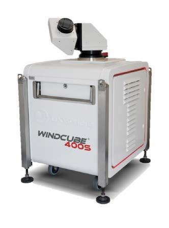
The WindCube Scan series of wind and aerosol lidars perform 24/7 real time measurements and high-level data processing. They are versatile tools for recovering accurate real-time wind and aerosol backscatter measurements in any scanning geometry up to more than 10 km. They are among the most flexible and accurate wind measurement technologies available, complementing met masts and accurate vertical profiling lidars in wind energy applications, for example.
Versatility and robustness WindCube Scan units feature rugged, industrial design and can be placed in extreme environments. Each system is fully configurable for several uses including monitoring, atmospheric crosssectioning, wind profiling, and more. State of the art structure detection algorithm offers the capability to detect, locate, and classify clouds and aerosol layers in the troposphere, as well as to monitor the height of the atmospheric boundary layer (ABL). They can be deployed either as standalone units for wind hazards detection, or in combination with other weather sensors as part of comprehensive systems like windshear alert systems at airports.
The WindCubeâ Scan series provides accurate wind and atmospheric measurements reliably and a ordably even in extreme environments.
17
WindCube Scan Lidar Features •24/7 real time measurements •Fully configurable for monitoring, cross-sectioning, wind profiling, and more •A wind reconstruction tool proven by international third parties is also •Dedicatedavailablereprocessing and display software
Storage capacity 1 TB* hard drive. Database storage autonomy depends on scenario. Typically 1 year (without saving raw signal averaged spectra, and with 1 second accumulation time). Data transfer RadialEthernet/LANWindSpeed file, 70 gates, 1s accumulation = 25 MB* /h Size proportional to the number of gates and the accumulation time. Synchronization UTC clock via NTP server and GPS Main functionnalities - Instrument control and -configurationManagement of a library of scans - Programming in a loop or a -schedulerReal-time data acquisition and measurement display - System diagnostics and alarms
Maximum operating altitude 3048 m (10 000 ft) IP rating IP65
Display range resolution Down to 1 m (with gate overlapping) 5 m in vortex mode Number of range gates Up to 320 (depending on range gate length used)
Operating environment Operating temperature −30 … +45 °C (−22 … +113 °F)
1)*: * TB = Tera Byte 2)*: MB = Mega Byte Windforge scanning scenarios
Scanning type Endless full hemispherical scanning Continuous scanning (scanner measures while rotating) 18
Lidar parameters
Shipping case only 100 kg (220 lb) Total with accessories 370 kg (816 lb) Laser Laser source Pulsed at 1.54 µm Lidar eye safety Class 1M according to IEC 60825 1:2014 Inputs and outputs
Accumulation time 0.1 … 10 s Down to 50 ms in vortex mode Range resolution25 m, 50 m, 75 m, or 100 m 75 m, 100 m, 150 m, or 200 m 34 m in vortex mode
Technical data
Compliance Compliance marks CE-marking
Scanner parameters
Elevation angle −19° … 199° (with 0.01° increment)
Scanning modes PPI: constant elevation angle scenario RHI: constant azimuthal angle DBS:scenariovertical wind profile wind Fixed:scenariofixed line of sight scenario
Power supply 100 … 240 VAC, 18 … 9 A RMS, 47 … 60 Hz With mains supply voltage fluctuations up to ±10 % of the nominal voltage Power consumption 500 … 1600 W (range includes the use of coolers and heaters)
First range measurementof More than twice the range gate length 68 m in vortex mode
Mechanical specifications
Scanner rotation speed Up to 30°/s Azimuth angle 0° … 360° (with 0.01° increment)
Shipping case closed 948 × 1204 × 1507 mm (37 32 × 47.40 × 59.33 in)
Shipping case opened 948 × 2736 × 1905 mm (37.32 × 107.72 × 75.00 in) Weight System only 232 kg (511 lb)
System requirements for Windforge software Processor Core i3 or better Operating system Windows 7 Memory 4 GB RAM Hard disk space 500 GB Resolution 1366 × 768 Data format Stored in an embedded SQL database. Export in auto documented NetCDF files by graphical user interface, API, or to an FTP server. The Leosphere NetCDF file format is built on NetCDF 4 (which is in turn built on HDF5) and its architecture is based on CfRadial2 and Cf convention.
Dimensions (L × W × H) System 830 × 1012 × 1370 mm (32.68 × 39.84 × 53.94 in)
Property 100S/200SWINDCUBE 400SWINDCUBE 200SWINDCUBEAT
Radial backscatter coe cient Attenuated relative beta (m-1.sr-1) Attenuated absolute beta (m-1.sr 1) Range Property 100SWINDCUBE 200S(-AT)WINDCUBE 400S(-AT)WINDCUBE
Performances When several Windcubes are programmed simultaneously, they can keep synchronized in time up to 0.5 s after running 1 h
Structure Residual planetary boundary layer Mixing planetary boundary layer CloudsAerosols
1) As defined in ISO 28902-2:2017, the maximum acquisition range is the maximum distance to which the lidar signal is recorded and processed. It depends on the chosen range resolution. The maximum acquisition range is 14.7 km in 100 m mode for a 100S or 200S( AT) and and >15 km in 200 m mode for a 400S( AT).
IntegratesimultaneouslyWindCube data easily in a third-party software Create a custom-made file format using JSON data stream
Technical data System behavior data
1)The Windcube scan pointing accuracy specification is 0.1°. This value has to be understood after alignment on distant hard targets, on a limited area, ±22.5° in elevation or azimuth, around a reference hard target and without considering possible backlash, that is, using always the same scanning direction.
Memory 8 GB RAM Storage Capacity: 1 TB (depending on campaign duration) Interface: SATA III 6.0 GB/s Single track seek time: •Read: 0.6 ms •Write: 0.8 ms Resolution 1366 × 768 Rights Local admin rights Basic display and export Animated data visualization Vortex (optional) Vortex measurement and aircraft vortex characterization www.vaisala.com
System requirements for post-processing software Processor Core i5 or i7 and 3.4 GHz or better Operating System Windows 7 and 10 or Windows server 2012R2 (64 bit)
•Latitudefor: and longitude (°) •Pitch and roll (°) •Disk occupation (%) Status (CSV format) OK/WARNING/CRITICAL for: •Overall view (lidar status) •Precise view (components status) •Measurement thresholds (for example temperature, disc space) Activity (CSV format) Time Actionsstamp(LOG IN/OUT, START/STOP Acquiring, START/STOP Operating) User information
2)Accuracy must be understood as absolute mean error of the radial wind speed, after filtering by the status and in a regular lidar measurement situation: diffuse particles, no hard target in the direct line of sight, no ambiguities.
Possible uses Change the automaticallyprogrammingaccordingto wind Programdirection several Windcubes
The maximum operational range is the distance to which a confident wind speed can be derived from the lidar signal. It depends on various parameters such as the accumulation time, physical range resolution, visibility, type of aerosols, and variations of refractive index in the atmosphere.
1)Close to extremal values, wind speed can be less accurate, according to the resolution used.
Radial wind Radial wind speed (m/s) Radial wind speed dispersion (m/s) Carrier to noise ratio (dB) Confidence index
Scanner pointing accuracy 1) 0.1°
Lidar performance
Wind data exports
Maximum typical operational range 1) 3000 m 6000 m 10 000 m Maximum acquisition range 1) 14 700 m14 700 m>15 000m
19
Environmental data (CSV format)30 minute average, minimum, maximum, and number of samples
Vertical profile wind (in DBS mode)Horizontal wind speed (m/s) Wind direction (m/s) Vertical wind speed (m/s) Carrier to noise ratio (dB) Confidence index Spectra (activate upon request)Spectral density Particles data exports (optional)
Scanner performance
Radial wind speed range 1) −30 … 30 m/s Reconstructed wind speed range (DBS scan) 0 … 60 m/s for 60° elevation angle 0 … 115 m/s for 75° elevation angle Radial wind speed accuracy 2) < 0.1 m/s
API API type REST Web API Functionalities Lidar configuration and programming Status/Activities/Logs monitoring Data download (JSON stream or NetCDF files)
Based on pulsed Doppler heterodyne laser principle, the WindCube sends a light pulse at a high frequency into the atmosphere and observes the signal backscattered by aerosols naturally present in the air. The time between the pulse and the detection of the backscattered signal is processed by the system thanks to the Doppler effect, and provides an accurate measure of the wind speed and direction.
Pulsed laser technology
The web based WindCube Insights platform enables remote monitoring and control of the WindCube vertical profiler. Wind speed data and carrier-to-noise ratio (CNR) are displayed live, and the platform also provides the possibility to configure measurement heights and communication with the Lidar.
Ease of installation and operations
The Lidar is easy to handle and install. A couple of hours is enough to fully set up the lidar and start measuring. It is compatible with autonomous power solutions (power pack, solar panels), and its robustness supports operations continuity.
Remote monitoring
Pulsed Lidars send laser pulses at a very high frequency. To avoid confusing time delays and distance, the Doppler shift is analyzed before the next laser pulse is emitted. Therefore, the probe distance, or height, only depends on the time it takes for a pulse to be received after it has been emitted. Multiple heights are measured simultaneously, and spatial resolution is constant throughout the entire wind profile. Also, measurement is not affected by clouds, fog, high density of dust, or obstacles.
20
WindCube Ground-based Vertical Profiler Lidar Features •Measurement from 40 meters to over 300 meters •Pulsed lidar technology • 4 inclined beams and 1 vertical •45beamWnominal power •Remote monitoring through WindCube Insights •Multiple communication channels (wired, cellular, satellite) •Optional autonomous power kit
Thanks to a vertical beam, the lidar allows a direct measurement of the vertical wind speed, and improves the turbulence intensity (TI) assessment.
WindCube® is a ground-based vertical profiler Lidar that measures accurate wind data up to over 300 meters. It is equivalent to a very tall met mast, collecting wind speed, direction, vertical wind speed, and turbulence intensity data at 20 di erent heights with limited installation constraints and high operational safety.
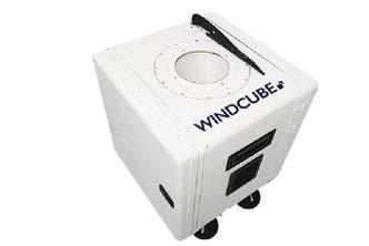
Insights secured cloud-based server Data file format RTD and STA (file), UTF 8 encoding Communication LAN, USB, 3G, or 4G router (router availability depends on the region/country), Modbus RTU (gateways available), Wi Fi Time synchronizationGPS, NTP Mechanical specifications Cube dimensions (L × W × H) 554 × 566 × 554 mm (21.81 × 22.28 × 21.81 in) With feet and wiper 608 × 566 × 661 mm (23.94 × 22.28 × 26.02 in) Weight 59kg (system only) 28kg (shipping case only) 91kg (total with accessories) Compliance Compliance marks (1) CE, FCC, IC 1)As verified on WindCube without Geofencing option www.vaisala.com
1)Nominal power consumption taken from an initial state of the WindCube at 15°C.
Electrical and optical Power consumption (1) 45 W between -5°C and 30°C / 23°F and 110W86°Fbelow - 5°C / 23°F 55W over 30°C / 86°F
Technical data Measurement parameters
LASER Safety Compliance 1M Class / EN 60825 1:2014
Environmental Protection Designed for installation in many kinds of weather and environmental IP66conditionsandIP67 (Inner sub-assemblies) IP54 (Lidar Casing) Radiation +1000W/m² at +45°C Rain protection Wiper Marine atmosphere (Salt Atmosphere Compliance) IEC 60068-2-52 (2017) – 120 hours
Measurement range (1) 40 … > 300 m Data sampling rate1 Hz Measuring distances20 user-defined distances simultaneously Radial Wind Speed range-23m/s to +23m/s
Data output Output data 1 s / 1 , 2 , 5 , 10 minute averaged (user-defined) horizontal and vertical wind speed Standard deviation CNRDirection(carrier-to-noise ratio) GPS Datacoordinatesavailability Complex measurementsterrain FCR unlimited license Data storage 120 GB industrial disk (over 5 years storage of all data)WindCube
Reconstructed Wind Speed range 0m/s to 49m/s
Warranty 3 years standard Preventive maintenance 3 years cycle (factory or onsite maintenance)
Shocks and vibration ISTA/FEDEX 6B
Maximum altitude 3000m (when equipped with DC-DC convertor) Operating humidity 0 to 95% RH (non-condensing)
Temperature range (1) 30°C to +45°C / -22°F to 113°F (chamber conditions)
21
1)Starting the system at low temperature (lower than -20ºC) will require to have the WindCube equipped with an adapted protection
1)Height from WindCube feet. Data availability depends on environmental factors such as visibility, type of aerosols and variation of refractive index in the atmosphere 2)For 10-min averages, as assessed by several 3rd parties on multiple WindCube devices or in 2020 according to IEC 61400-12-1 Ed.2. Uncertainty figures are Final Accuracy Class divided by √3 Operating environment
Reconstructed Wind Direction range 0 – 360° Speed accuracy (2) 0.1 m/s Wind speed 0 … > 60 m/s Speed uncertainty (2) 40 – 80m: 1.4% to 2.6% 80 – 120m: 0.6% to 1.4% 120 – 135m: 0.6% to 0.8% Direction accuracy (2) 2° Beam geometry 4 inclined beams at 28° and 1 vertical beam
WindCube Offshore
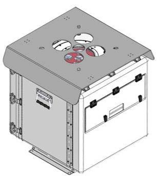
The WindCube Offshore can be used offshore and onshore, according to your needs. A customized version of the WindCube has been designed for harsh offshore locations like floating buoys, substations and vessels. For Offshore wind farms located further away, the WindCube Offshore allows measuring accurately the wind on stable platforms located several kilometers from the shore, even in harsh offshore environments. In case of absence of platform, the measurement with a Lidar installed on a buoy/vessel, is the most effective way of performing a costeffective wind resource assessment.The WindCube Offshore is based on the same technology than the standard WindCube Lidar with a marinized robust casing and base in order to stand harsh marine conditions, it has been reinforced to operate for extended periods in harsh sea conditions (saltwater, humidity and bird presence).
WindCube O shore is a vertical profiler Lidar that measures accurate wind data up to over 300 meters. It is equivalent to a very tall met mast, collecting wind speed, direction, vertical wind speed, and turbulence intensity data at 20 di erent heights with limited installation constraints and high operational safety. For O shore uses, on buoy or fix platform installation, Leosphere designed a marinized version of the WindCube Vertical Profiler Lidar. Both Casing plus internals are IP67 and specifically tested to resist harsh environment for years of sea operation.
Remote monitoring
Pulsed lidars send laser pulses at a very high frequency. To avoid confusing time delays and distance, the Doppler shift is analyzed before the next laser pulse is emitted. Therefore, the probe distance, or height, only depends on the time it takes for a pulse to be received after it has been emitted. Multiple heights are measured simultaneously, and spatial resolution is constant throughout the entire wind profile. Also, measurement is not affected by clouds, fog, high density of dust, or obstacles. Thanks to a vertical beam, the lidar allows a direct measurement of the vertical wind speed, and improves the turbulence intensity (TI) assessment.
The web based WindCube Insights platform enables remote monitoring and control of the WindCube vertical profiler. Wind speed data and carrier-to-noise ratio (CNR) are displayed live, and the platform also provides the possibility to configure measurement heights and communication with the lidar.
ff f Features •Measurement from 40 meters to over 300 meters •20 range gates •Pulsed lidar technology •4 inclined beams and 1 vertical •45beamW nominal power •Remote monitoring through WindCube Insights •Multiple communication channels (wired, cellular, satellite) •IP67 Casing + IP67 Internals • Classified
Pulsed laser technology
Ease of installation and operations
Based on pulsed Doppler heterodyne laser principle, the WindCube sends a light pulse at a high frequency into the atmosphere and observes the signal backscattered by aerosols naturally present in the air. The time between the pulse and the detection of the backscattered signal is processed by the system thanks to the Doppler effect, and provides an accurate measure of the wind speed and direction.
22
The lidar is easy to handle and install. A couple of hours is enough to fully set up the lidar and start measuring. It is compatible with autonomous power solutions (power pack, solar panels), and its robustness supports operations continuity.
Laser safety 1M Class / EN 60825 1:2014 Compliance Compliance marks CECE, FCC, ICES
WindCube Offshore technical data
Preventive maintenance 3 years cycle at factory or service center or onsite onshore Temperature range* -30°C to +45°C / -22°F to 113°F (chamber conditions)
Solar radiation protection Sunshade Environmental Protection Designed for installation in many kinds of weather and environmental IP66conditionsandIP67 (Inner sub-assemblies) IP54 (Lidar Casing) Radiation +1000W/m² at +45°C Rain protection Wiper Marine atmosphere IEC 60068 2 11, 4 to 5 years sea operation equivalence Shocks and vibration ISTA/FEDEX 6B
Cube dimensions (H × W × D) 677 mm × 585 mm × 592 mm Weight 52 kg Electrical and optical Power consumption 45 W nominal Temperature range −20 … +40 °C (-4° +104°F)
(*) Starting the system at low temperature (lower than -20ºC) will require to have the WindCube equipped with an adapted (**)protection.Asverified on WindCube without Geofencing option Mechanical specifications
Insights secured cloud-based server Data format RTD and STA (file), UTF 8 encoding Communication LAN, USB, 3G, or 4G router (router availability depends on the region/country), Modbus RTU (gateways available), Wi Fi, Satellite Time synchronizationGPS, NTP www.vaisala.com 23
Measurement range40 … > 300 m Data sampling rate1 Hz
Measurement parameters
Operating humidity 0 to 95% RH (non-condensing)
Operating environment
Warranty 3 years standard, extendable once after maintenance
Measuring distances20 user-defined distances simultaneously Wind speed measurement0.1 m/s Wind speed 0 … > 60 m/s Wind speed uncertainty2 … 3 % (following IEC 61400 12 1 Ed. 2) Wind direction accuracy2° Beam geometry 4 inclined beams at 28° and 1 vertical beam Data output Output data 1 s / 1 , 2 , 5 , 10 minute averaged (user-defined) horizontal and vertical wind speed Standard deviation CNRDirection(carrier-to-noise ratio) GPS Datacoordinatesavailability Complex measurementsterrain FCR unlimited license, option only available for fixed installation Motion softwarecompensation External reprocess software, option available for buoy installation, unlimited license Geofencing 3 years license, option only available for fixed installation Data storage 120 GB industrial disk (over 10 years storage of all WindCubedata)
Lightning Network Health
IRIS
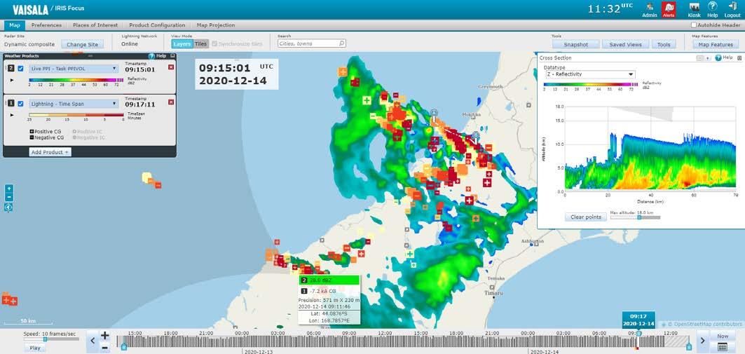
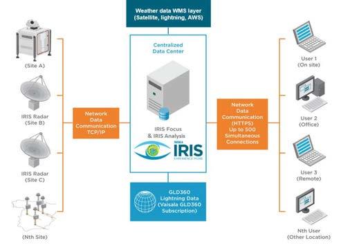
Weather products are graphical representations of the data captured by the remote sensing devices, such as weather radars, lightning networks, and products are based on raw data from the IRIS back end systems (IRIS - Interactive Radar Information System and/or TLP - the Total Lightning Processor). IRIS Focus processes this data and generates on demand products in real time. On demand products provide control over the presentation of this data. You can combine data from several remote sensing devices into composites to provide an expanded area of coverage.
On-demandlidars.
With the Network Health product, you can visualize the performance of the lightning sensor network.
Customizable map view
24
IRIS Focus Remote Sensing Software provides a rich set of unique tools for viewing and analyzing your weather data from various sources: weather radars, lidars, and lightning networks. IRIS Focus helps you better understand storms for quicker decisions and more accurate precipitation classification. IRIS Focus weather products
The map view can be customized by adding WMS layers from external sources, such as satellite images or radar data from external radar networks.
Focus Remote Sensing Software
Weather radar data: courtesy of Meteorological Service of New Zealand Ltd. Lightning data: courtesy of Transpower New Zealand Ltd.
Radar-based nowcasting
Features •Web-based application • Easy-to-configure events and •On-demandalerts data regeneration at high •Testedresolutionandaudited with the latest security standards
IRIS Focus can provide alerts for weather events, such as the approach of a severe storm, turbulence, or flood potential for user-defined areas of interest.
Nowcasting performs advection calculations on motion data from radar products to predict weather movement and severity up to 2 hours in the future.
Events and alerts
Integrated weather data visualization Integrated data from various sources enables you to better understand storms and other weather phenomena for more accurate forecasts and earlier alerts.
Network requirements Communication from IRIS Analysis and the TLP to IRIS Focus Network data transfer>100 Mbit/s (1000 Mbit/s recommended) Communication from IRIS Focus to IRIS Analysis and the TLP Single user (1 seat)Network data transfer> 650 kbit/s Latency ~150 ms Multiple simultaneous users 5 seats > 3.5 Mbit/s 10 seats > 7 Mbit/s 20 seats > 14 Mbit/s Hardware requirements Minimum Recommended1) •Modern 4-core CPU (Intel Xeon E5 series or similar) •24 GB RAM 2) •1 TB •1400HDDx1050 minimum screen resolution •Modern 8-core CPU (Intel Xeon E5 series or similar) •32 GB RAM •2x 1 SAS TB HDD in RAID 1 •1920configurationx1200screen resolution 1)The pre-installed IRIS Focus system delivery option uses the Dell PowerEdge R440 rack server unit, which meets the recommended hardware setup. 2)For a small installation with only a few users, 16 GB of RAM is sufficient. Software requirements Browser IRIS Focus supports current Microsoft Edgeâ, Mozilla Firefoxâ, and Google Chrome™ browsers. Operating systemAlmaLinux 8 IRIS Analysis IRIS 8.13.6 or later. IRIS Analysis provides radar products through a proprietary socket server connection. TLP TLP 1.2.7 Weather products On-demand product Weather product BASE Echo Base BEAM Antenna Beam Pattern CAPPI Constant Altitude PPI HMAX Height of Maximum Intensity Product MAXLAYER Maximum Data MLHGT Melting Level Height MVF Motion Vector Field Network Health Lightning network performance PPI Plan Position Indicator RAIN1 Hourly Rain Accumulation RAIN-N N-Hour Rain Accumulation RHI Range Height Indicator RTI Range Time Indicator SRI Surface Rainfall Intensity SHEAR Wind Shear SLINE Shear Line (frontal boundary) THICK Echo Thickness TimeSpan Lighting event evolution TOPS Echo Tops Map VAD Velocity Azimuth Display VIL Vertically Integrated Liquid VVP Velocity Volume Processing WARN Warning/Centroid WIND Wind Speed and Direction www.vaisala.com 25
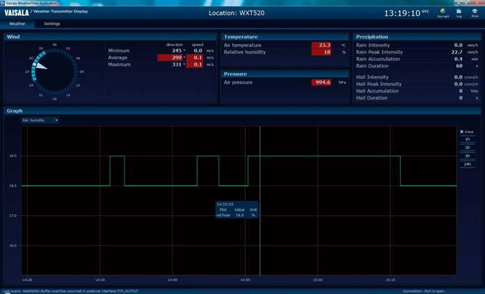
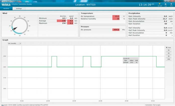
Vaisala Weather Transmitter Display MCC201 is PC software designed for use with Vaisala Weather Transmitter WXT520. It is used for displaying and storing the meteorological measurement data needed for planning weather critical operations and examining longer-term weather phenomena or climatological trends.
Real-Time Display
Vaisala Weather Transmitter Display presents meteorological data in numerical and graphical formats. Users can choose from a range of engineering units when displaying the latest measurement values on the easy-to-use default screen layout. The default weather parameters monitored include wind speed and direction, air temperature, relative humidity, atmospheric pressure and precipitation. Observation data can also be displayed as a real-time graph. Visual and audible alarms provide warnings of critical weather conditions or other important issues such as sensor or system failure.
Weather
26
MCC201 day-time color scheme
Data Distribution
MCC201 Transmitter
The application automatically stores data chronologically as ASCII log files, and continues to run in the background so that data collection can continue even when the user interface is closed. The ASCII log files can be exported to external applications so that collected data can be viewed in tabular or graphical formats.
Data Archiving and Viewing
The data distribution feature allows several client PCs to gather weather data from the master PC. The file transfer feature allows the latest data files to be transferred to another server using FTP protocol.
Display MCC201 night-time color scheme Features •Displays and logs data from Vaisala Weather Transmitter •EasyWXT520toinstall and operate •Provides data for various weather •Highapplicationscontrast day-time and nighttime color schemes •Visual and audible alarms •Remote client PC display option and FTP client support
Technical Data
Minimum Hardware Requirements
Personal Computer Desktop/Laptop Processor 2.0+ GHz RAM 2048 MB Hard Disk Space Software: 100 MB Data storage 1 GB/Year Ports Serial/USBEthernet/LANport (may require an adapter) Monitor resolution 1024 x 768 pixels (or higher)
Full-screenWindAlarmsRose mode Data logging and viewing Received data log Observation parameter log Event Tabularlogview
Data distribution Support for client PCs FTP client support
Features
Precipitation accumulation reset www.vaisala.com
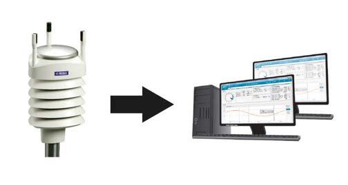
Vaisala Weather Transmitter Display MCC201 can connect with WXT520 via LAN, wireless GPRS, or USB/serial connections with ports RS-232 or RS-485.
Drives DVD required for installation Operating system
Communication options between WXT520 and PC Serial connection via RS-232 port Serial connection via RS-485 (requires converter) USB connection via RS-232/RS-485 (requires converter) TCP/IP via Ethernet (requires converter)
27
Monitored default weather parametersWind speed and direction Air temperature and relative humidity Atmospheric pressure Precipitation Data collection Automatic background data Datacollectionvalidation
Connecting with WXT520
Real-time display Text boxes, graphs, and labels
Operating systems Windows 10, Windows 7, Windows XP, Windows 2008 Server, Windows 2003 Server
Implementing a scalable, flexible management solution with autonomous systems and intelligent field devices of different brands and types which provide interfaces for e cient integration with other products and systems will allow you to optimize your network operations, improve safety and facilitate operation in remote locations.
From implementation to long-term maintenance, a network management solution optimized for your needs improves operational efficiency and reduces the lifetime cost of managing and maintaining all your observation sites.
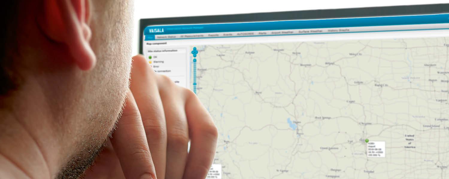
Vaisala Observation Network Manager NM10 enables remote monitoring, management and control of your weather observation networks on one central, secure, and automated platform. Easy access to all essential event, alert, observation, device status, metadata and maintenance information helps to identify and solve problems quickly ensuring continuous high-quality observations and shorter site visits with correct actions.
Cost-effective, configurable off-the-shelf platform
Real-time monitoring with alerts and remote diagnostics NM10 provides the ability to monitor individual site status via secure web technologies and collect data 24/7 from one central network in real time. It allows your team to remotely access and control individual sites to fix the problems faster and optimize your network operation. With centralized event, alert, notification, device metadata and maintenance information quicker reaction to network and sensor failures, and faster problem identification and solution deployment can be achieved for improved network uptime and data availability. In addition, configure the layout and displayed data to clearly visualize and understand precisely real-time weather conditions throughout your country or region affecting your operations and observation site performance. High data security, availability and validity Perform automatic real-time data quality control and analytics services to feel confident that you will get the highquality observation data you need. Advanced data security and user management capabilities are utilized to avoid network vulnerability and to mitigate the risks of intrusion and cyber threats. 28
NM10 Observation Network Manager Benefits •Operational cost savings with more e cient operation and •Fastmaintenanceremoteproblem solving •Automatic continuous data availability and validity analysis and •Securereporting24/7monitoring of observation sites •Web interface for sharing realtime surface weather and other information
Vaisala Observation Network Manager NM10 enables remote monitoring and control of your weather observation networks on one central, secure and automated platform. An off-the-shelf solution with extensive support and proven performance and functionality significantly reduces the implementation time and total lifetime costs, helping you stretch your budget further.
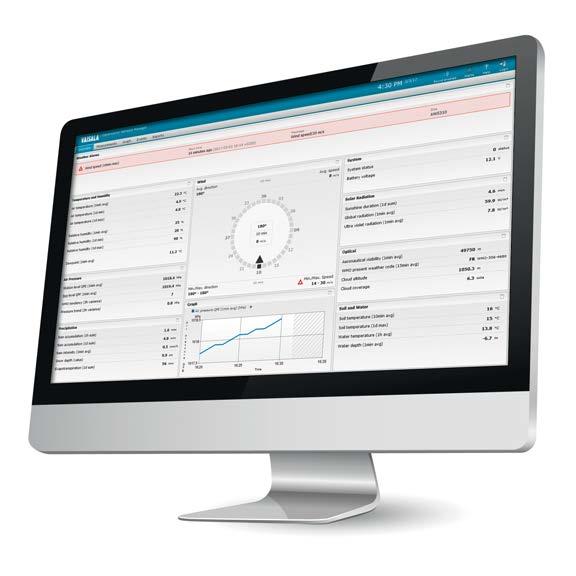
Surface Weather Display Views
Text view to list observations in numeric and string format.
Precisely understand current and past surface weather and environmental conditions a ecting your operations on a single or a group of sites.
Surface weather alarm information optionally also visualized on GIS map and list views.
Access to administrator view for user management and system settings.
Wind rose view with optional road or runway direction indication to inform about current wind conditions. Chart view to inform about current and past surface weather and environmental conditions.
Remotely control observation sites directly from the application desktop. Receive notifications when problems occur.
Context sensitive help to use the application.
Remotely monitor, access and control the sites connected to avoid unnecessary site visits. Monitoring overall status of the observation network using GIS map, list and detailed site views. Verify the quality of observation data. Manage device metadata and maintenance activities. 29
Remotely access observation sites to further diagnose issues.
Default desktop view customizable by system administrator to include new pages and layouts for di erent users.
Observation Network Management Views
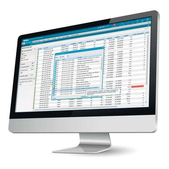
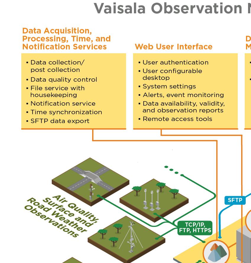
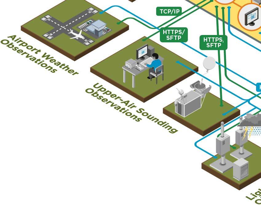
Data acquisition, processing, time, and notification services component provides the capabilities to receive air quality, surface, road and airport weather observations as well as events and alerts information from airport weather, upperair sounding, weather radar and lightning detection observation systems. Variety of different communication protocols and message formats can be used. The component is also able to synchronize time, manage the post-collection of the observations from the Vaisala automatic surface weather stations and provide central data quality control service.
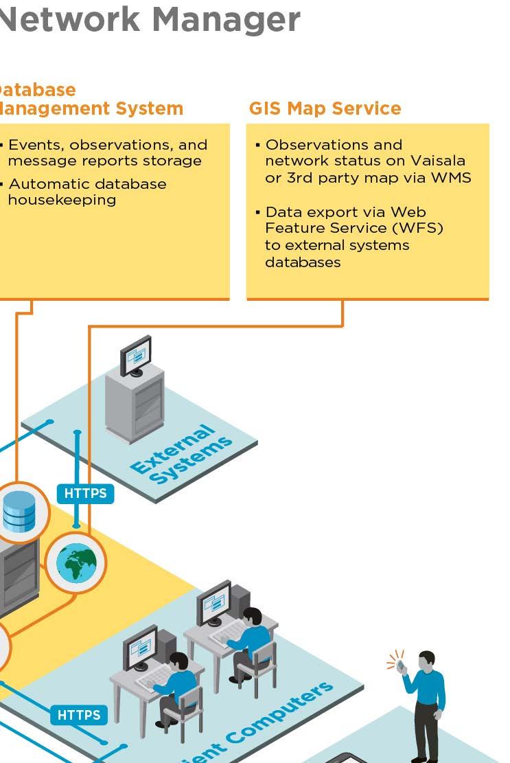
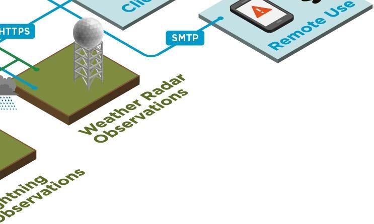
NM10 is a stand-alone system installed in customer premises on Windows or Linux operating systems. The system is configured individually for each customer use. The figure shows the available main components and interfaces of the system.
Email, visual and sound alarms and notifications are available.
System events, state changes, observations and message reports received from the observation sites are persisted to a scalable database management system.
A browser-based user interface via HTTPS restricted by username and password is provided for viewing the observation data and for monitoring the data quality and the status of the network and its components. Geographic information system (GIS) map, list, site details, wind rose, chart, text and report widgets are available to view real-time and history observations, site statuses and their exact locations. Depending on the site and its configuration, links are included for remote access to view and diagnose the connected devices and systems without the need to use any additional software on client PCs. 30
•Sound
Minimum system requirements
•Standardmap
•GeoServer
•Vaisala weather transmitters •Vaisala air quality transmitters
Technical data Features
•Vaisala surface weather stations •Vaisala ceilometers •Vaisala AviMetâ airport systems •Vaisala AUTOSONDEâ systems •Vaisala DigiCORAâ sounding systems •Vaisala RWS200 road weather stations •Vaisala weather radars •Vaisala lightning detection systems •ASCII string message parsing from third-party surface weather sensors and systems (when applicable)
•Context
•Observationreleasedata
•OGC SensorThings RESTful HTTP service Data post collection Vaisala surface weather stations Data processing •Range, step, and persistence checks for surface and road weather transmitter and station observations •Generic statistics, wind, sun radiation and solar specific central calculations •Gain and offset correction for air quality •MGRSmeasurements(NATOUTM) coordinate support Data storage •PostgreSQL •Observationdatabaseandevent log text files • Configurable database management system Time services •Time synchronization for Vaisala surface weather stations •NTP system time synchronization Notification services Configurable SMTP email alerts Remote site access • Terminal connection for weather transmitters and stations, RDP over HTTPS for airport, AUTOSONDEâ and DigiCORAâ sounding systems •Web browser connection via HTTPS to AUTOSONDEâ and DigiCORAâ sounding systems, RWS200, and lightning detection systems Metadata management Manual maintenance and device metadata management Web user interface •Client connection via HTTPS •User authentication and administration •User configurable desktop and widgets list, graph, wind rose, text and IFRAME widgets settings alerts, events monitoring acknowledgement: grant or deny balloon reports availability and validity reports and device metadata management views for local language(s) sensitive help GIS map service with OpenStreetMap world map max. zoom level: 1:433K map max. zoom level: 1:6759 interface for third-party map data Data export WFS via HTTPS WMO FM 94 BUFR Ed 4 v. 29.0.0 (Fixed land station synoptic reports, ref. 3 07 080)
•Data
•Enhanced
Data acquisition
•FTP/SFTP,
•System
•Map,
•Translation
•WMS
Processor 2.0+ GHz, 4-core CPU or higher RAM •8 GB or higher (with standard GIS map) •16 GB or higher (with enhanced GIS map)
•Alarm
•Maintenance
Hard disk space 300 GB or higher (with standard GIS map) 1 TB or higher (with enhanced GIS map)
Operating system •Microsoft Windows Server 2012 R2 •Microsoft Windows Server 2016 •Microsoft Windows 10 Professional •Microsoft(64bit) Windows 10 Enterprise Embedded (64bit) •Linux CentOS 7.2 •Linux CentOS 7.3 •Linux Ubuntu 16.04 LTS (64-bit)
Installation environment On-premise computer hardware or virtual environment instance Ethernet 10/100/1000 MB Other peripherals USB drive, UPS Web browsers Microsoft Edge latest versions Microsoft Internet Explorer 11 Mozilla Firefox latest versions Google Chrome latest versions Monitor resolution 1366 x 768 or higher Exact system requirements for computer hardware are dependent on the number and type of observation sites connected, amount of data collected, data acquisition interval(s), data storage time, maximum number of concurrent web clients connected, and features selected by the customer. For further information and more detailed specifications, please contact Vaisala. www.vaisala.com
31
•Automatic
Device Mounting Capacity MDF101 includes a standard DIN-rail, which enables the mounting of practically any DIN-mountable devices to the frame. The maximum number of devices that can be installed in MDF101 is limited by the width of the DIN rail (420 mm (16.54 in)) and the number of power outputs in dual power supplies (16).
Common Device Mounting Examples MDF101 is commonly used for installing DXL421 modem units and 1-port port servers in Vaisala Central Data Unit rack applications. For example, a total number of 16 DXL421 modem units can be installed on the frame.
The MDF101, DXL421 modem, and port server entity is a modular system for replacing legacy product Midas Communication Unit MCU111 in Vaisala Central Data Unit rack applications. The modular design of the entity provides higher system redundancy and faster Mean Time To Repair (MTTR).
A total number of 12 1-port port servers can be installed to MDF101. In a setup where both DXL421 modem units and 1 port port servers are installed to the same MDF101 unit, a total number of 6 DXL421 modem units and 6 1-port port servers can be installed side by side.
Device Entity as Legacy MCU111 Replacement
MDF101 Device Mounting and Powering Frame Features •Standard DIN rail for mounting •Roomdevicesfor 16 DXL421 fixed-line modem units and 12 1-port port •Installationservers on 19-inch standard device rack
Serial data cables from DXL421 modems can be connected either to a single 16 port port server, or to multiple 1 port port servers to achieve additional redundancy in sensor data communication. Both serial-to-LAN conversion options are supported by Vaisala Central Data Unit rack applications. The 16-port port server is installed directly to the 19-inch device rack, and multiple 1-port port servers are installed to MDF101.
Dual Power Supply MDF101 comes with dual power supplies, each providing power to half of the mounted devices. In addition, for 1 port port servers their dual power input makes it possible to wire the dual power supplies as dual redundant power supplies. 32
•Dual power supply Vaisala Device Mounting and Powering Frame MDF101 is designed for mounting and powering DIN-rail mountable devices to system device racks in Vaisala Central Data Unit (CDU) rack applications. MDF101 can be installed on standard 19-inch device racks.
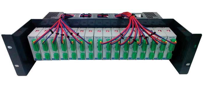
Storage
Operating Environment
Data
Dimensions (H × W × D) 132 × 483 × 212 mm (5.20 × 19.02 × 8.35 in) Weight (as empty) 1700 g (3.75 lb) Mounting options 19-inch rack Frame material S235JR steel, RAL7024 powder painted DIN-rail design Standard DIN-rail DIN-rail width 420 mm (16.54 in)
Inputs and Outputs
Operating temperature -40 ... +55 °C (-40 ... +131 °F) Storage temperature -40 ... +60 °C (-40 ... +140 °F)
Technical
Mechanical Specifications
Compliance Safety EN60950-1 EMC compliance CISPR 22, Class B (EN55022) Approvals CE marking Vibration and shocks ETS 300 019-2-4, class 4M5 (for Power Supplies) MDF101 back panel and dual power supplies www.vaisala.com 33
Input voltage 100-240 VAC (90 ... 264 VAC) Input frequency 50/60 Hz (45 ... 65 Hz) Input connection 3-pole pluggable screw terminal (R7.62 mm)
Operating humidity 2 ... 85 %RH, non-condensing humidity 2 ... 85 %RH, non-condensing
Output voltage 15 VDC Output current (at 15 VDC) 4 0 A Max. output power 60 W (× 2) Output connection 8-pole pluggable screw terminal (R5.08 mm)
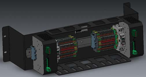
34
Communication Unit Options CDU401 includes several communication unit options. Communication units are selected according to your application and needs. Options include enterpriseclass network switches, routers, VPN routers, device port servers, leased-line modems, and SFP modules. Units can also be duplicated for additional reliability. Built-In Safety Features CDU401 includes separate surge protection for input power, input serial (RS485/RS232), and input modem lines.
The number of rack servers can be adjusted in line with the needs of the application and according to your wishes. The servers can also be duplicated for additional reliability.
Easy Maintenance and Access CDU401 has lockable doors on the front and back for easy and controllable maintenance access. Both doors are perforated for optimal airflow and cooling. Servers are installed onto sliding rails for easy maintenance, and all cables are clearly marked. The rack display provides easy access for system maintenance. CDU401 and AviMetâ AWOS
The system’s application software is installed in CDU401’s servers. The rack includes high reliability, rackmountable servers and additional communication unit hardware to connect the servers to field sensors, workstations, and other external interfaces included in the system. CDU401’s display options include professional KVM (Keyboard-VideoMouse) rack console displays and simpler desktop displays on the rack shelf. For added reliability, CDU401 can also be powered by an optional UPS mounted in the same rack. Rack Server Computers CDU401 utilizes standard commercial off-the-shelf enterprise-class rack servers with high reliability. The server specifications are designed to meet and exceed the needs of Vaisala’s weather system application software products. This means that smooth operation and su cient storage space for the application in question can be ensured by using standard Vaisala-selected rack Vaisala-selectedservers. rack servers are a costeffective solution, eliminating the need to overspecify computing power or storage space. Server reliability is further improved with internal redundancy, in the form of duplicated, and mirrored hotswap hard drives, as well as duplicated hot-swap power supplies.
In airport weather observation systems, reliability and high availability are essential. For increased system reliability, duplicated rack servers are recommended for AviMet AWOS, RVR, and LLWAS systems. Vaisala AviMet software includes dual hot-swap and failover functionalities: if the active server fails, the backup server immediately takes over operations. The AviMet software is divided into numerous modules, and if one of these fails on the active server, the backup server assumes operation of the failed module.
Surge arrestors protect the equipment from potential damage caused by lightning and poor or variable power
Vaisala Central Data Unit Rack CDU401 is the main computer for the weather monitoring system.
For Collecting, Processing, Visualizing, Distributing, and Storing System Data at Central Sites
CDU401 Central Data Unit Rack Features •Highly configurable to meet any application and customer need •Sturdy steel housing protects sensitive •Lockableequipmentperforated doors on front and back for optimal airflow and easy, controllable access •Separate surge protection for input electricity, input serial, and input modem lines •Optional UPS for continuous operation during short power •Optionaloutages server and communication duplication for increased reliability
Itquality.isrecommended to include optional backup power (UPS) in CDU401. The UPS protects against system downtime, data loss, and process interruption by providing continuous, clean power during short power outages. The optional UPS for the CDU401 includes an extra battery module that provides su cient backup power for at least two hours of operation.
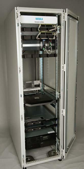
Operating Environment Operating temperature +5 … +40 °C (+41 … +104 °F) Operating humidity 5 … 90 %RH, non-condensing Inputs and Outputs Input voltage 120/230 VAC (120 V : 90 ... 138 VAC 230 V : 160 ... 276 VAC) Input frequency (45 ... 65 Hz) Optional backup power (UPS)2000 VA/1800 W UPS and extra battery (providesmoduleatleast 2 hours of backup power) Surge protection Input electricity, input serial (RS485/ RS232), input modem Communication Interfaces Copper Ethernet (LAN) RJ45 connectors, CAT5e Fiber Optic with SFP modulesLC Duplex, SM/MM, 100/1000 Fiber Optic with converters RS485 (2-wire) Serial (RS485 / RS232) Krone terminal (LSA-Plus) Leased-line modem Krone terminal (LSA-Plus) Mechanical Specifications Installation location Indoors in clean, dry room on flat, stable floor Installation height for components42 U Installation width for components19" standard rack Rack material Sheet steel, dipcoatprimed/ powdercoated (light gray) RAL 7035 Doors Lockable perforated doors on front and back Dimensions 2030 x 600 x 1080 mm (H x W x D) Weight 120–350 kg (varies according to included equipment) Compliance Safety IEC/EN 60950-1 EMC IEC/EN 55022, IEC/EN 55024 Approvals CE marking www.vaisala.com 35
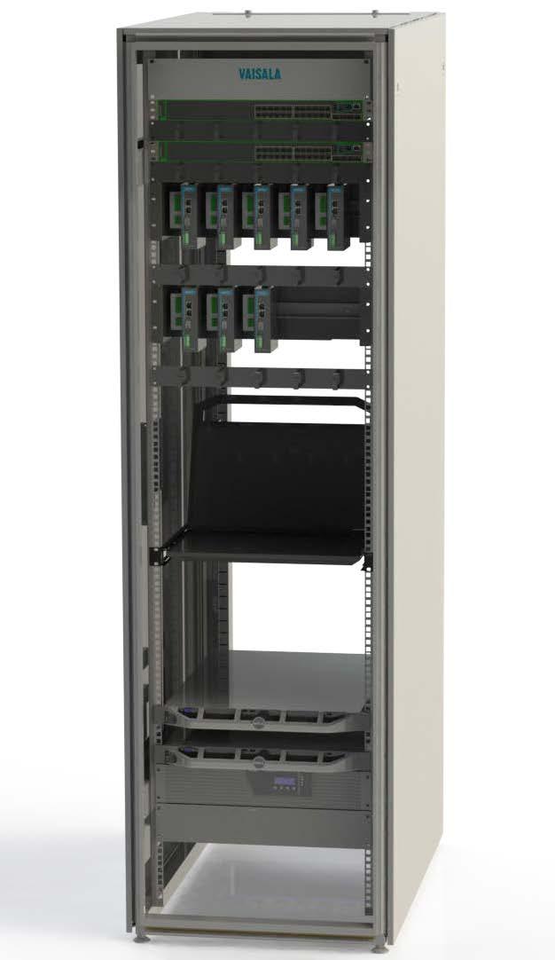
RME111 Radio Modem Enclosure for Central Site Features
•Robust
•Separateequipmentsurge
Mast options include mounting support for 63mm, 75mm, 102mm, 106mm pole masts, and mounting support for DKP11 and DKE200 lattice masts. DKP711 frangible 1.2m fiberglass mast and DKP721 frangible 2.0m fiberglass mast can also be bought with RME111.
RME111 includes separate surge protection for input electricity, input antenna cable, and output serial data cable (RS485 / RS232). These surge arrestors are protecting the radio modem units and power supply from damages caused by lightning activity and bad or varying electricity quality.
Needed frequency dependent components are included in the Vaisala Radio, Combiner, and Antenna Set RCA111, or as separately selected items. The radio modems, combiners, and antennas will be fully installed and integrated to RME111, so the end result is fully working and tested radio communication system for central site.
•Recharging
Safety Features Included
Radios, Combiners, and Antennas RME111 itself does not include fixed radio modem units, radio antenna combiners, or radio antennas, because these components are frequency dependent. This choice has been made to increase flexibility of RME111, because these frequency dependent components can vary between different customer, country, or project specific needs.
RME111 is a connection box that provides enclosure, mounting, powering, backup battery, surge protection, and needed internal cabling for radio modem units, and also for radio antenna combiners, when needed. Radio Modem Housing Capacity RME111 can contain up to 8 radio modem units and 2 radio antenna combiners, as standard. The number of radio modem interfaces can be flexibly selected between 1 and 8 to meet the needs in a cost effective way. Vaisala has designed the RME111 unit for certain selected and field proven radio modem models. Compatibility with other radio modem models should be verified separately. RME111 can house also up to 2 radio antenna combiners. One radio antenna combiner can be used to combine 2-4 radio modem units to use only single receiving end radio antenna instead of multiple antennas. By using combiners the amount of radio antennas installed at central site can be decreased, and excess antennas in the radio mast can be avoided. RME111 can also be used without combiners, but this is recommended only, when only few radio modem units are RME111needed.includes also 10m antenna signal cables, as standard, for the needed radio antennas. Installation Options RME111 can be installed indoors or outdoors, and to wall or mast. Indoor wall installation is the most commonly needed option and there only the IP66 stainless steel enclosure is needed. In outdoor wall or mast installations also mounting frame, radiation shield, and cable cover are needed. Mounting frame enables different mast installation options, radiation shield protects the enclosure from excessive solar radiation, and cable cover protects cable throughputs in outdoor environment.
•Room for 8 radio modem units and 2 combiners as standard and tight (IP66) stainless steel housing protecting sensitive protection for each antenna cable, data output cable, and power input backup battery for continuous operations through short power outages
RME111 includes also recharging backup battery for continuous operations through short power outages. The battery provides backup power for at least 6 hours for 2 radios and for at least 2 hours for 8 radios.
Vaisala Radio Modem Enclosure for Central Site RME111 is used for enabling and combining weather sensor data radio communication between field sensor sites and central site. 36
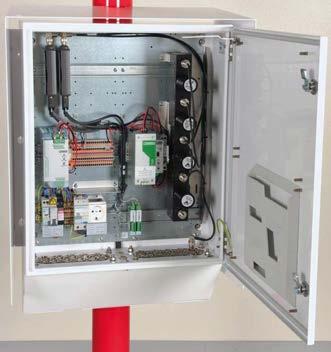
Technical Data Operating Environment Operating temperature −40 … +60 °C (−40 … +140 °F) Storage temperature −50 … +70 °C (−58 … +158 °F) Operating humidity 0 … 100 %RH, non condensing Storage humidity 0 … 100 %RH, non condensing Compliance EMC compliance IEC/EN 61326-1 Electrical safety IEC/EN 60950-1 Vibration IEC 60068-2-64, 5-500Hz 2G-RMS 30 min, 3 axes Shock IEC 60068-2 27, 25G-peak 11 ms 6 pulses IP rating IP66 Approvals CE marking Inputs and Outputs Input voltage 100 … 240 VAC (90 ... 264 VAC) Input frequency 50 ... 60 Hz (45 ... 65 Hz) Input connection 3-pole pluggable screw terminal (R7.62 mm) Surge protection For input electricity, input antenna cable, output serial (RS 485/RS 232) Rated current 10 A Input Current on Full Load 115 VAC Approx. 2.3 A 230 VAC Approx. 1.15 A Socket outlet inside the enclosure100 … 240 VAC, 10 A AC/DC power supply inside the enclosure 24 VDC, 10 A, e ciency > 93 % Backup battery 2.6 Ah / 12 V (provides backup power for 6 h for 2 radios and 2 h for 8 radios) Mechanical Specifications Dimensions (H × W × L), including radiation shield and cabling box 787 × 581 × 270 mm (30.98 × 22.87 × 10.63 in) Dimensions (H × W × L) 600 × 500 × 211 mm (23.62 × 19.69 × 8.31 in) Weight with radiation shield and cabling box Approx. 40 kg (88 lb) Weight 20 kg (44 lb) Color White (RAL9003) Frame material Acid-proof stainless steel AISI316, Powder coat (white) RAL9003 RME111 housed with 8 radios and 2 combiners www.vaisala.com 37
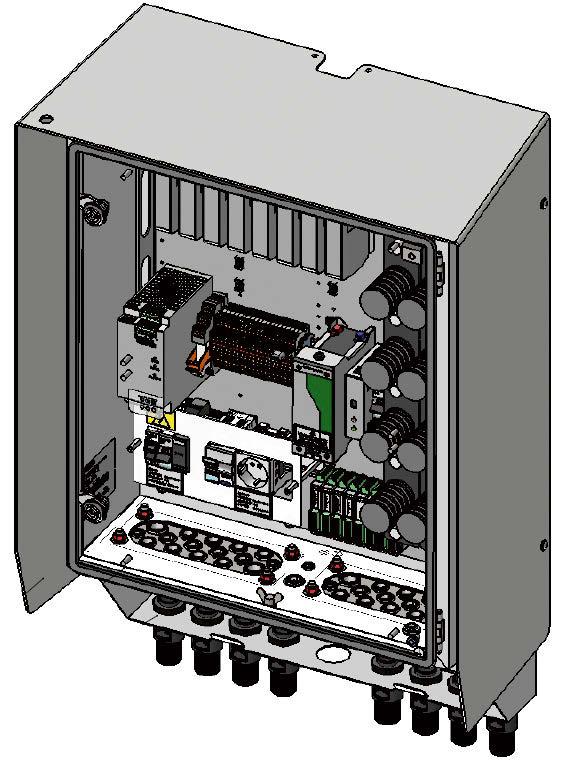
The box also includes recharging backup battery to enable continuous operation during short power cuts. The battery provides su cient backup power for approximately one hour of operation.
38
The 1.2 meter frangible composite mast DKP711 and 2 meter frangible composite mast DKP721can be purchased in conjunction with FOC201. These masts are strongly recommended for FOC201 installations at airports. Frangible structures are mandatory in areas adjacent to runways. Vaisala frangible pole and lattice masts are impact tested and comply with both ICAO and FAA frangibility standards. These masts comply with the frangibility requirements set out in part 6 of the Aerodrome Design Manual, First Edition, 2006, and the FAA AC 150/5345 45C –Low Impact Resistant Structures, 2007.
The device configuration can be adjusted in order to meet individual customers’ needs in a cost-effective manner. FOC201 is compatible with selected field-proven device port servers and managed network switch models. Compatibility with other models should be verified separately. Installation options FOC201 can be installed indoors or outdoors, either wall or mast mounted. Outdoor mast installation is the most common choice, and for this reason the connection box includes an IP66 stainless steel enclosure, mounting frame, radiation shield, and cable cover. The mounting frame makes different mast installation options possible. The radiation shield protects the enclosure from excessive solar radiation. The cable cover protects the cable throughputs in outdoor environments. Mast-mounting options include support for 63 , 75 , 102 , and 106 millimeter pole masts, and DKP11 and DKE200 lattice masts.
FOC201 provides enclosure, mounting, power, a backup battery, and surge protection for device port servers and the managed network switch. It also includes an RS 485 serial input for data from field sensors, fiber connection boxes for terminating the customer’s fiber cable, and the associated internal cabling. Communication equipment housing capacity FOC201 can contain up to 4 device port servers, 1 managed network switch, and 2 fiber connection boxes as standard.
Multiple fiber communication options FOC201 supports several fiber optic communication network options: both single-mode and multi-mode, and singlefiber ring, dual-fiber ring, and point-topoint network topologies. Suitable SFP modules for different kinds of fiber optic networks can also be included.
Safety features FOC201 includes separate surge protection for the input power and input serial data cable (RS 485). These surge protectors protect the device port server units and power supply from potential damage caused by lightning activity and poor or variable-quality electricity.
FOC201 Field Communication Box Features •Connect up to 4 separate sensor sites to the fiber optic network with RS 485 •Multiple fiber communication •Multipleoptions mast-mounting options •Durable, weatherproof (IP66) stainless steel housing to protect sensitive equipment •Separate surge protection for data and power input cables •Rechargeable backup battery ensures continuous operation during power cuts
Vaisala Field Communication Box FOC201 is a connection box that converts sensor data in the field for use by the rest of the weather system. It enables, for example, sensor data to be connected in copper line serial format (RS 485) to the customer’s existing fiber network in AviMetâ systems.
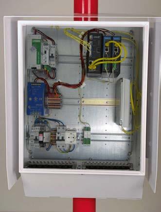
Inputs and outputs Input voltage 100 … 240 V AC, ±10 % Input frequency 50 … 60 Hz Input connection 3 pole pluggable screw terminal (R7.62 mm) Input current 10 A maximum Surge protection For AC (mains) input, serial input (RS 485)
Overvoltage category II Socket outlet inside the enclosure100 … 240 V AC, 6 A AC/DC power supply inside the enclosure 24 V DC, 10 A, e ciency > 93 % Backup battery 2.6 Ah / 12 V (provides backup power for 1 hour) Fiber optic network options Fiber mode Single mode / Multi mode Network topology Single ring / Dual ring / Point to point Device port servers 0 … 4 units 1) Managed network switch 0 … 1 units 1) SFP modules 0 … 4 modules 1) Fiber connection boxes 0 … 2 units 1) 1)All are needed for functioning serial-to-fiber entity. Choosing 0 units means project-specific solution. FOC201 with 1 managed network switch, 4 port servers, and 2 fiber connection boxes
Technical data Operating environment Operating environment Outdoor use Use in wet location Yes Operating temperature 1) −40 … +60 °C (−40 … +140 °F) Storage temperature −50 … +70 °C (−58 … +158 °F) Operating humidity 0 … 100 %RH, non condensing Storage humidity 0 … 100 %RH, non condensing Pollution degree 2 Maximum operating altitude 3000 m (approx. 9800 ft) IP rating IP66
EMC compatibility EN 61326 1, industrial environment Electrical safety EN 61010 1 Vibration (random) IEC 60068 2 64 (5 … 500 Hz 2G RMS 30 min, 3 axes) Shock IEC 60068 2 27 (25 G peak, 11 ms, 6 pulses)
Compliance EU directives and regulations Low Voltage Directive (2014/35/EU) EMC Directive (2014/30/EU) RoHS Directive (2011/65/EU) amended by 2015/863
39
1) For backup battery operating and storage temperature, see manufacturer documentation. Mounting options DKP202W, DKP203W Ø 63 mm (2.48 in) pole mast DKP204W Ø 75 mm (2.95 in) pole mast DKP206W, DKP206AV, DKP210W, DKP210AV Ø 102 mm (4.02 in) pole mast DKP711, DKP721, DKE100 (DKE110F) Ø 106 mm (4.17 in) pole mast DKE200 Lattice mast Wall-mounting screws included.
Frangibility, pole and lattice mastsICAO Aerodrome Design Manual, First Edition, 2006, Part 6 – Frangibility FAA AC 150/5345 45C – Low Impact Resistant Structures, 2007 Compliance marks CE, RCM www.vaisala.com
•Robust,
Standard safety features RSI51 includes surge protection for inputpower, input closing contacts, and output serial data (RS 485/RS 232). The surge protectors protect the unit from potential damage caused by poor or variable power quality or other possible surges.
The Vaisala Runway Light Setting Interface Unit RSI51 is a sensor that provides data on the current light intensity setting on the runway lighting system as well as on the current runway-in-use settings.
40
•Surgeelectronicsprotection for
RSI51 converts the data from the switches or relays into a message for the AviMet system. Each of the maximum 6 light setting values corresponds to a 0 to 100 mA input that is converted into a corresponding number in the AviMet message. Only one active input at a time is possible. The AviMet system converts the number into the corresponding runway light intensity setting value defined in the AviMet configuration file. Installation options RSI51 can be installed indoors, either mounted on a wall with screws or on a DIN rail with an mounting kit. DIN rail mounting kits are supplied as standard.
Operating principle RSI51 provides runway light intensity setting information to the airport’s AviMet system. Runway light intensity setting information is collected from a runway lighting system switch or relays, normally located on the air tra c control tower.
RSI51 Runway Light Setting Interface Unit Features and tested for Vaisala AviMetâ systems tightly sealed polycarbonate housing protects input power, input closing contacts, and output serial data closing contacts for runway lighting system switch or relay
•8
The runway light intensity data is integrated into Vaisala AviMet RVR calculations, AviMet systems can also use runway-in-use data to indicate the current runway in use.
•Designed
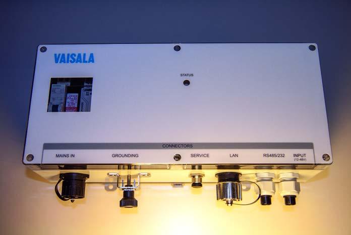
Weight
41
No Operating temperature
data Operating environment Operating environment Indoor
Overvoltage
Operating humidity 0
Technical use Use in wet location −20 … +55 °C (−4 … +131 °F) −40 … +65 °C (−40 … +149 °F) … 100 %RH, non condensing … 100 %RH, non condensing altitude m (approx. 9800 ft) and voltage 100 … 240 V AC, ±10 % Input frequency … 60 Hz Input current 100 mA Surge protection Input electricity, input closing contacts, output serial (RS 485/ RS 232) category II Data input options 8 × closing contact from manual switch or relay 12 … 48 DC voltage message Data output options Serial (RS 485/RS 232), Ethernet/LAN Service connection Serial RS 232 (H × W × D) 216 × 360 × 111 mm (8.50 × 14.17 × 4.37 in) 3.5 kg (7.72 lb) (PC), light gray RAL7035 DIN rail mounting kit included in the Wdeliveryall-mounting screws not included
Enclosure material Polycarbonate
Inputs
Storage humidity 0
Compliance EU directives and regulations Low Voltage Directive (2014/35/EU) EMC Directive (2014/30/EU) RoHS Directive (2011/65/EU) amended by 2015/863 compatibility EN 61326 www.vaisala.com
Storage temperature
EMC
1, industrial environment Electrical safety EN 61010 1 Cold IEC 60068 2 1 Dry heat IEC 60068 2 2 Damp heat, cyclic IEC 60068 2 30 Vibration ETSI EN 300 019 2 2 Compliance marks CE, RCM
3000
Mechanical specifications Dimensions
Pollution degree 2 Maximum operating
Mounting options
outputs Input
50
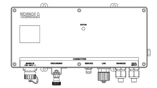
•Stand-alone
WID511 has a full-size intuitive touch screen with a graphical user interface for easy navigation between separate wind data views – such as sensor pages – as well as simple display setting changes with straightforward item selection. Each wind sensor view is in wind rose and alphanumeric formats as default, suitable for operational use at airports in accordance with ICAO wind data display standards and recommendations. WID511 can collect data from multiple wind sensors with a four-times-persecond interval as recommended by ICAO and WMO. To receive data from a Vaisala wind sensor, such as Vaisala WINDCAPâ Ultrasonic Wind Sensor WMT700, Ethernet and RS 485 connections are standard. There are visual and audible alarms in all views to warn of serious events, such as message or system failures. To prevent unauthorized changes to the display settings, a PIN code is required to access advanced settings in the maintenance mode.
42
interface •High
WID511 AviMet Wind Panel Display Features high-performance wind panel display, compliant with latest ICAO standards screen with intuitive graphical user contrast day-time and nighttime color schemes with display brightness calculations, look panel, installation times maintenance electrical and mechanical design
and virtually
free •Robust
WID511 uses a compact 5.7 inch LCD screen suitable for aviation-related operating environments such as air tra c control towers, where excellent readability in both bright and dim light is required. The display is controlled using an easy-to-use resistive touch screen, with a clear, uncluttered user interface for simple operation.
Integrated touch screen for efficient operations
Vaisala AviMetâ Wind Panel Display WID511 is designed for viewing real-time measurements from Vaisala wind sensors in aviation applications, in accordance with the latest ICAO standards and recommendations.
control •Coherent
and feel with Vaisala AviMetâ systems •Visual and audible alarms •Desktop,
and •Easy-to-userecommendationstouch
Robust display with high performance WID511 is robust, designed and tested for demanding industrial electromagnetic and environmental specifications. It is equipped with a resistive touch screen that can be controlled with either bare or gloved hands, or any other suitable can be mounted in different ways depending on where it is installed. It can be easily mounted on a standard IEC panel, desktop, or wall.
Theobject.display
and wall mounting options •Short
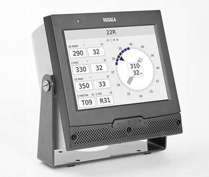
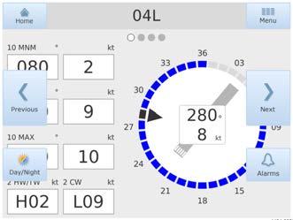
Technical data Operating environment Operating temperature 0 … +40 °C (+32 … +104 °F) Storage temperature −20 … +80 °C (−4 … +176 °F) Operating humidity 2 … 95 %RH, non condensing IP rating IP20 Flammability class UL94 V 0 Inputs and outputs Supply voltage 12 … 28 V DC Maximum power consumption at +20 °C (+68 °F) 15 W Typical power consumption at +20 °C (+68 °F) 4 W Data interfaces Ethernet (10/100 MBit/s), RS 422, RS 485, RS 232 Display specifications Display 5.7 inch TFT LCD, 640 × 480 VGA resolution, > 500 cd/m2 luminance Brightness control Manual User input interface Touch screen Audible alarm > 80 dB(A) at 1 m (3 ft 3 in), 2 kHz User interface Observation mode Wind data pages Navigation mode •Switch between data pages •Alarm •Day-timelogand night-time views •Access to maintenance mode Maintenance mode •Display cleaning (wipe) mode •Touch screen calibration •Volume setting •Brightness setting •Product information view •Advanced settings (PIN login) • Configuration settings • Configuration file import/export •Software update Displayed values Wind speed and direction According to ICAO standards and •3recommendations:secondand2 minute average •10 minute minimum, maximum, and •Headwind,variationtailwind, crosswind Compliance EU directives and regulations Low Voltage Directive (2014/35/EU) EMC Directive (2014/30/EU) RoHS Directive (2011/65/EU) amended by 2015/863 EMC immunity EN 61326 1, industrial environment EMC emissions CISPR 32 / EN 55032, Class B Drop test compatibility MIL STD 810G 516.6 Procedure IV, Free Fall (Rough Handling) Vibration compatibility MIL STD 810G 514.6C 3 Procedure I, Cargo Vibration Test Compliance marks CE, RCM, UKCA Mechanical specifications Housing material PC/ABS Mounting options Panel, desktop, wall Panel installation standard compatibility IEC 61554 Panel mounting aperture dimensions 138 × 138 mm (5.43 × 5.43 in) Panel mounting frame dimensions144 × 144 mm (5.67 × 5.67 in) WID511 day-time and night-time color schemes www.vaisala.com 43
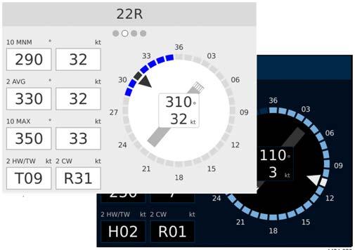
WID512 has a full-size intuitive touch screen with a graphical user interface for easy navigation between separate data pages – as well as simple display setting changes with straightforward item selection. Each data page contains 3 data rows with 3 columns. Typically one data label, one value, and one unit are shown on each row.
WID512 is designed for viewing important information in aviation applications in a simple way.
WID512 uses a compact 5.7 inch LCD screen suitable for aviation-related operating environments such as air tra c control towers, where excellent readability in both bright and dim light is required. The display is controlled using an easy-to-use resistive touch screen, with a clear, uncluttered user interface for simple operation. Robust display with high performance WID512 is robust, designed and tested for demanding
IECItwaysThehands,controlledresistivespecifications.electromagneticindustrialandenvironmentalItisequippedwithatouchscreenthatcanbewitheitherbareorglovedoranyothersuitableobject.displaycanbemountedindifferentdependingonwhereitisinstalled.canbeeasilymountedonastandardpanel,desktop,orwall.
The display supports up to 16 pages of information. Data shown on it is controlled by the host computer with a message format defining the content of each displayed page.
WID512 can be used for different data viewing purposes, most commonly it is used as a back up display for the AWOS system main user displays. The dispaly is connected to the data sending unit, like the AWOS, via Ethernet or RS 485 connection.
There are visual and audible alarms in all views to warn of serious events, such as message or system failures. To prevent unauthorized changes to the display settings, a PIN code is required to access advanced settings in the maintenance mode. 44
Integrated touch screen for efficient operations
Vaisala AviMetâ Data Panel Display
Features •Generic data panel display for aviation •Easy-to-usepurposestouch screen with intuitive graphical user interface •High contrast day-time and nighttime color schemes with display brightness control •Coherent look and feel with Vaisala AviMetâ systems •Visual and audible alarms •Desktop, panel, and wall mounting options •Short installation times and virtually maintenance free •Robust electrical and mechanical design
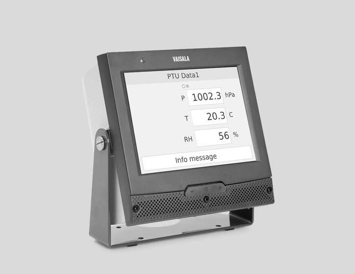
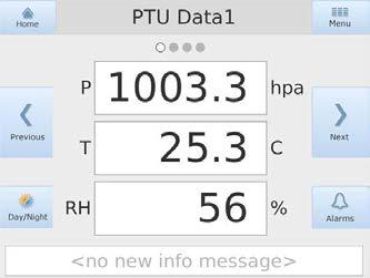
Technical data Operating environment Operating temperature 0 … +40 °C (+32 … +104 °F) Storage temperature −20 … +80 °C (−4 … +176 °F) Operating humidity 2 … 95 %RH, non condensing IP rating IP20 Flammability class UL94 V 0 Inputs and outputs Supply voltage 12 … 28 V DC Maximum power consumption at +20 °C (+68 °F) 15 W Typical power consumption at +20 °C (+68 °F) 4 W Data interfaces Ethernet (10/100 MBit/s), RS 422, RS 485, RS 232 Display specifications Display 5.7 inch TFT LCD, 640 × 480 VGA resolution, > 500 cd/m2 luminance Brightness control Manual User input interface Touch screen Audible alarm > 80 dB(A) at 1 m (3 ft 3 in), 2 kHz User interface Observation mode Up to 16 data pages with a header text box and 9 alphanumeric text boxes Navigation mode •Switch between data pages •Alarm •Day-timelogand night-time views •Access to maintenance mode Maintenance mode •Display cleaning (wipe) mode •Touch screen calibration •Volume setting •Brightness setting •Product information view •Advanced settings (PIN login) • Configuration settings • Configuration file import/export •Software update Compliance EU directives and regulations Low Voltage Directive (2014/35/EU) EMC Directive (2014/30/EU) RoHS Directive (2011/65/EU) amended by 2015/863 EMC immunity EN 61326 1, industrial environment EMC emissions CISPR 32 / EN 55032, Class B Drop test compatibility MIL STD 810G 516.6 Procedure IV, Free Fall (Rough Handling) Vibration compatibility MIL STD 810G 514.6C 3 Procedure I, Cargo Vibration Test Compliance marks CE, RCM, UKCA Mechanical specifications Housing material PC/ABS Mounting options Panel, desktop, wall Panel installation standard compatibility IEC 61554 Panel mounting aperture dimensions 138 × 138 mm (5.43 × 5.43 in) Panel mounting frame dimensions144 × 144 mm (5.67 × 5.67 in) WID512 day-time and night-time color schemes www.vaisala.com 45
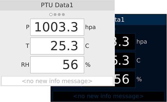
The display can be mounted in different ways depending on where it is installed. It can be easily mounted on a standard IEC panel, desktop, or wall. Integrated touch screen for efficient operations WID513 has a full-size intuitive touch screen with a graphical user interface for easy navigation between separate data pages – as well as simple display setting changes with straightforward item selection. There are multiple predefined data pages that can be set to be Theredisplayed.arevisual and audible alarms in all views to warn of serious events, such as message or system failures. To prevent unauthorized changes to the display
Vaisala AviMetâ Weather Panel Display WID513 is designed for viewing real-time weather information in accordance with ICAO standards and recommendations.
WID513 uses a compact 5.7 inch LCD screen suitable for aviation-related operating environments such as air tra c control towers, where excellent readability in both bright and dim light is required. The display is controlled using an easy-to-use resistive touch screen, with a clear, uncluttered user interface for simple operation. Robust display with high performance WID513 is robust, designed and tested for demanding hands,controlledresistivespecifications.electromagneticindustrialandenvironmentalItisequippedwithatouchscreenthatcanbewitheitherbareorglovedoranyothersuitableobject.
settings, a PIN code is required to access advanced settings in the maintenance mode. From these settings pages the authorized user can enter station specific parameters, such as declination and airport elevation.
WID513 weather panel display closeup of a clear, uncluttered user interface for simple operation 46
WID513 AviMet Weather Panel Display Features •Stand-alone high-performance panel display for wind, pressure, and temperature data •Easy-to-use touch screen with intuitive graphical user interface •High contrast day-time and nighttime color schemes with display brightness control •Coherent calculations, look and feel with Vaisala AviMetâ systems •Visual and audible alarms •Desktop, panel, and wall mounting options •Short installation times and virtually maintenance free •Robust electrical and mechanical design
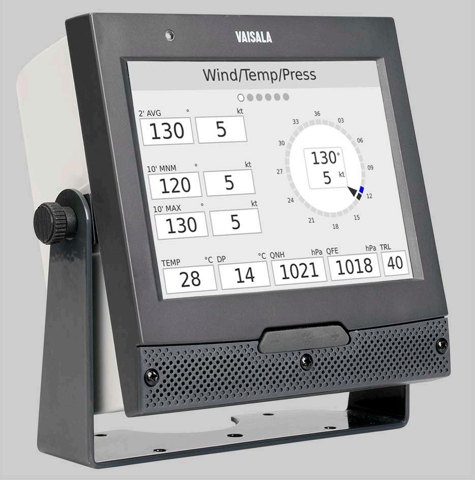
Technical data Operating environment Operating temperature 0 … +40 °C (+32 … +104 °F) Storage temperature −20 … +80 °C (−4 … +176 °F) Operating humidity 2 … 95 %RH, non condensing IP rating IP20 Flammability class UL94 V 0 Inputs and outputs Supply voltage 12 … 28 V DC Maximum power consumption at +20 °C (+68 °F) 15 W Typical power consumption at +20 °C (+68 °F) 4 W Data interfaces Ethernet (10/100 MBit/s), RS 422, RS 485, RS 232 Display specifications Display 5.7 inch TFT LCD, 640 × 480 VGA resolution, > 500 cd/m2 luminance Brightness control Manual User input interface Touch screen Audible alarm > 80 dB(A) at 1 m (3 ft 3 in), 2 kHz User interface Observation mode Multiple user selectable data pages Navigation mode •Switch between data pages •Alarm •Day-timelogand night-time views •Access to maintenance mode Maintenance mode •Display cleaning (wipe) mode •Touch screen calibration •Volume setting •Brightness setting •Product information view •Advanced settings (PIN login) • Configuration settings • Configuration file import/export •Software update Displayed values Wind speed and direction •3 second and 2 minute average •10 minute average, minimum, and maximum Temperature and humidity •Air •Relative•Dewtemperaturepointhumidity Pressure •Air •3•3•QFF•Transition•QFE•QNHpressurelevelhourtendencyhourtrend Compliance EU directives and regulations Low Voltage Directive (2014/35/EU) EMC Directive (2014/30/EU) RoHS Directive (2011/65/EU) amended by 2015/863 EMC immunity EN 61326 1, industrial environment EMC emissions CISPR 32 / EN 55032, Class B Drop test compatibility MIL STD 810G 516.6 Procedure IV, Free Fall (Rough Handling) Vibration compatibility MIL STD 810G 514.6C 3 Procedure I, Cargo Vibration Test Compliance marks CE, RCM, UKCA Mechanical specifications Housing material PC/ABS Mounting options Panel, desktop, wall Panel installation standard compatibility IEC 61554 Panel mounting aperture dimensions 138 × 138 mm (5.43 × 5.43 in) Panel mounting frame dimensions144 × 144 mm (5.67 × 5.67 in) www.vaisala.com 47
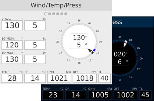
RWIS system consists of in-pavement sensors, sub-surface temperature probes, and a full suite of atmospheric sensors. Data from all sensors are collected and processed in an on-field remote processing unit (RPU). The data from RWIS system provides accurate and reliable information to improve the timing of airport maintenance deicing applications. Deicing chemical's effectiveness is determined by the surface temperature and not the air temperature.
Winter weather impacts our runways and taxiways very di erently than it impacts the atmosphere, so measuring specific runway conditions is critical. Accurate, realtime weather monitoring of the runways and taxiways is one of the most coste ective ways to ensure safe, continuous airport operations. Vaisala Runway Weather Information System (RWIS) is designed to provide airport sta with critical information to make informed decisions about treating, clearing, and maintaining the airport surface.
f Features •Reduces runway maintenance •Reducescosts chemical application based on reported conditions •Improves decision making and makes critical decisions easier •Ease of use lowers amount of training time required
Navigator Web Software RWISAirportStation SensorSurface Vaisala Cloud 48

Vaisala Navigator User Software
Vaisala becomes the airport’s weather partner by collecting RWIS reports, remotely monitoring the system and sensors, and archiving all data in our sophisticated redundant data centers.
Forecasting In addition to the IceBreak forecast model, Vaisala offers full forecasting services. Custom forecasts are generated for each airport customer and are delivered daily, including a daily outlook, 24-hour forecast, and 2-5 day forecast.
The Cloud allows you to feel safe that your data is protected, and available from anywhere you have internet, not just inside the airport network at the airport.
49
Vaisala’s unique cloud option enhances the RWIS user display by adding our proprietary IceBreak pavement forecasting model. Using the secure Vaisala Cloud also provides worry-free operations to the airport, decreasing downtime and eliminating the need for an on-site server.
Meteorological Consultants are available 24/7/365 for telephone and email consultations, and provide email, telephone, or text message alerts in case of weather events. Vaisala’s forecasting services are flexible and customizable to the airport’s particular needs. Maintenance Vaisala offers a comprehensive maintenance program that includes: remote monitoring, 24-hour telephone support, onsite support for outages, and replacement of failed components.
RWIS installed on an airfield –weather station with sensor suite (atmospherics) www.vaisala.com
Remote Services
Navigator Cloud Software
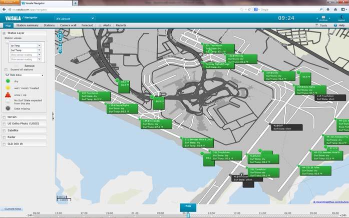
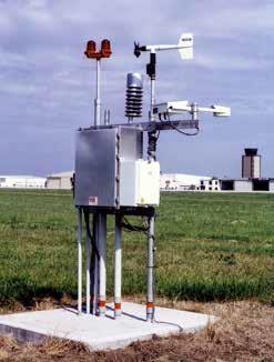
•Lightning magnetic field waveform storage capability at the •Capabilitysensorto generate and save raw sensor data locally for o ine reprocessing and archiving
LS7002 is a Total Lightning Sensor. It detects low frequency (LF) electromagnetic signals generated by lightning in order to provide extremely accurate geolocation capability with industry leading measurement of lightning strength and lightning type classification. LS7002 is the most costeffective network-based lightning detection solution for customers demanding high accuracy, reliability, ease of installation, and ease of LS7002maintenance.network uses a combination of magnetic direction finding and time-ofarrival techniques to deliver superior detection e ciency, optimal location accuracy, and system redundancy with fewer sensors than any other method for detecting cloud lightning pulses and cloud-to-ground lightning strokes. It provides large area coverage with fewer sensors, which leads to lower lifetime network ownership costs than any other technology.
•Compatible with previous generation Vaisala sensors: LS7000 and LS7001
•The most precise cloud-to-ground lightning detection, geolocation, and calibrated lightning
•Detects lightning events at long ranges (> 1500 km)
•Data buffering capability at the sensor in case of communication failure between sensor and Total Lightning Processor™
• E cient lightweight electronics module allows for ease of installation and maintenance with stand-alone, rooftop and indoor electronic mounting options
•Calibrated parameters for lightning events including time, location, amplitude, polarity, and waveform features
• Power utilities • Telecommunications Benefits
•Sensor electronics can be installed separately from the antenna, for example tower-mounted with custom cable sets or indoors to reduce potential physical damage from severe weather environments
Standard warranty
Vaisala warrants all products manufactured by Vaisala to be free from defects in workmanship or material for one year from the date of delivery. Contact your Vaisala Sales Representative for specific product service warranty details.
50
The latest in precision lightning technologygeolocation
Lightning data for a wide range of applications LS7002 provides real-time data that is recommended for operations that focus on tracking cloud and cloud-to-ground lightning threats to ground-based and airborne assets, including applications in:
•Independently validated 150 m median location accuracy for cloud-to-ground lightning strokes
•Detectsparametersahigh percentage of cloud lightning for early thunderstorm identification
Features
• Aviation • Defense • Forestry • Meteorology/Climatology
Total Lightning™ Sensor network detects cloud and cloud-to-ground lightning with high detection efficiency and excellent location accuracy. It uses combined technology and provides large area coverage with fewer sensors, which leads to lower lifetime network ownership costs than any other technology.
•Up to 95 % network detection e ciency for cloud-to-ground lightning and better than 50 % network detection e ciency for cloud lightning
LS7002 Total Lightning Sensor
Support services Training, technical support, and spare parts are available for maintaining optimal network and sensor performance. Contact your Vaisala Sales Representative for service agreement information.
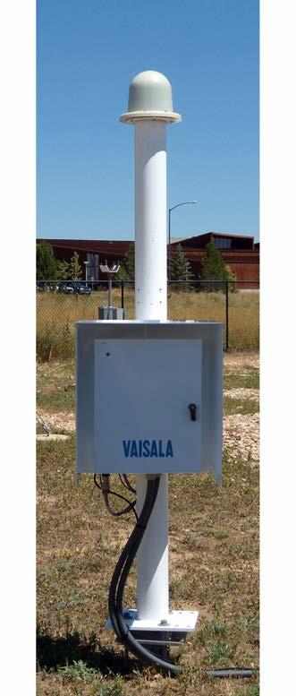
Operating temperature −40 … +55 °C (−40 … +131 °F) Operating humidity 0 … 100 %RH, condensing Maximum wind speed 240 km/h (149 mph) Maximum operating altitude 5500 m (approx. 18000 ft) Hail Ø 2.0 cm (0.79 in) Ice 8.0 cm (3.15 in) Rain 8.0 cm/h (3.15 in/h) at wind speed 65 km/h (40 mph) IP rating IPX4
Recommended baseline distances between sensors 15 … 350 km (9 … 217 mi) Min. number of sensors per network4 LF band 1 … 350 kHz Performance monitoring Complete automatic system calibration and self-test with manual capability Remote configuration Operational parameters are remotely configurable
Mounting
1)IC flash detection efficiency higher than 50 % can be achieved with network baseline distances shorter than 150 2)Performancekm. specifications are applicable to LS7002 networks that use the latest version of Vaisala Total Lightning Processor 3)Median network location accuracy can be better than 150 m in the interior of the network.
Operating environment
Inputs Time synchronization Source: GPS receiver Accuracy: 50 ns to UTC Communication interfaces TCP/IP Max. 64 kbps per data stream depending on network geometry and gain settings RS 232 serial Maintenance port for optional on-site connection AC input to 48 V DC output power supply options Indoor AC/DC power supply 90 to 264V AC at 50/60 Hz input Outdoor AC/DC power supply100 to 130 V AC at 50/60 Hz input Outdoor AC/DC power supply200 to 240 V AC at 50/60 Hz input (H × W × D) × 54 × 50 cm (86.61 × 21.26 × 19.69 in) Weight 50.1 kg (110 lb) Concrete ground
220
pad Non-ground mounting options available 388361 368 411 224 27 406 351 Ø 127 406 508 2207 271 39580508919 200 Ø13253269 322537 619 Compliance UL standard UL 61010 1 CAN/CSA certfication C22.2 NO. 61010 1 f f f f f f www.vaisala.com 51
Measurement performance Lightning type Cloud (IC) and Cloud-to-ground (CG) lighting events and flashes Network flash detection e ciency 1)2) CG: 95 % IC: 50 % Network median location accuracy 2)3) 150 m (492 ft)
and outputs
Mechanical specifications Dimensions
FALLS Client serverTLD/FALLS LS7002 LS7002LS7002 LS7002 TLP 52
Lightning detection network With an improved licensing schematic, all Vaisala precision lightning detection network configurations will come with a TLP200 configuration, enabling the capability to use both LF and VHF Eachtechnology.network consists of 4 or more sensors (depending upon desired coverage area). Each sensor sends back data from detected lightning-generated electromagnetic signals to the TLP in TLPreal-time.usesthis data from multiple sensors along with a geolocation algorithm to find the optimum location solution for each lightning event. In addition, a variety of parameters and associated characteristics are reported for each solution. Lightning data from the TLP can be sent to different applications for display, storage, and analysis. IRIS Focus
Features •Continuous monitoring of remote sensor performance and communication status •Location propagation correction service for improved location •Dynamicaccuracy monitoring of network location accuracy and detection e •User-friendly,ciency web-based •Geolocatinginterface of multiple pulses in lightning generated pulse-bursts
Total Lightning Processor™ processes data from both Vaisala’s low frequency (LF) and very high frequency (VHF) sensors providing lightning location solutions for greater than 90 % of Cloud to Ground (CG) and 50 % of Cloud (IC) lightning flashes for LF and greater than 90 % of both CG and IC lightning flashes for VHF.
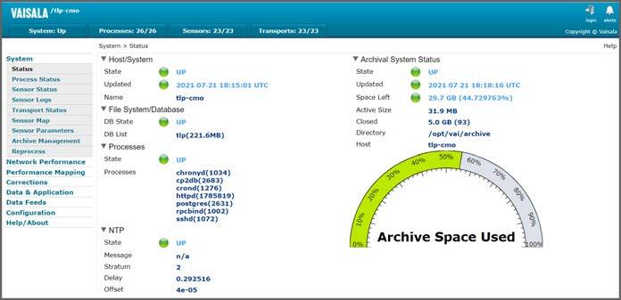

•Networkmonitoringperformance mapping
53
Continuous monitoring Vaisala Total Lightning Processor continuously monitors remote sensor performance and communication status. This allows sensor owners to validate that the sensor is operational and functioning to specifications.
Benefits •Enhanced lightning classification using multiple waveform parameters • Improved archive management •Bettertools location accuracy for cloud lightning pulses
Advanced featuresgeolocationlightningwithflexible
The revolutionary technology in Vaisala Total Lightning Processor is designed with multiple performance levels to meet the needs of a wide range of applications. Users are no longer required to determine which features are most important to their operation as Vaisala has decided to centralize the offering into one license level, which includes all available features. This license includes the following features: and sensor performance
•Dynamic detection e ciency (DE) and location accuracy (LA) projections
•Advanced lightning type classification, “burst” processing, and waveform parameters These features provide more e cient network operations, stabilized performance, and deliver advanced information about the geolocated lightning events. TLP combines Vaisala’s latest patented location algorithm with terrain and propagation correction services, significantly improving the network median location accuracy to 250 meters or better in the interior of the network. With Vaisala’s newest sensor technology, a location accuracy approaching 150 meters can be achieved.
User-friendly, web-based operation Vaisala Total Lightning Processor is available on a Linuxâ operating system for added flexibility and lower ownership costs. TLP employs a web-based interface with excellent network monitoring tools.
•System
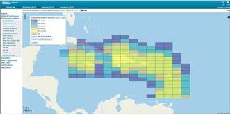
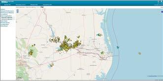
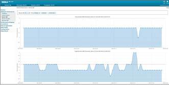
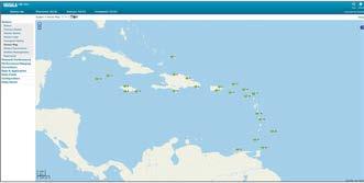
Operating altitude −16 … 3048 m (−50 … 10 000 ft) Storage altitude −16 … 10 600 m (−50 … 35 000 ft)
tools •Sensor Map • % Positive •% Optimized •% Cloud •CG Detection E ciency •CG Location Accuracy •IC Detection E ciency •Lightning
•Lightning
•
Communication interfaces Supported interfaces TCP/IP Certified web browsers Operating system Web browser Version Microsoft Windowsâ 10Internet Explorerâ 20H2 Microsoft Windowsâ 10Mozilla Firefoxâ 78 Microsoft Windowsâ 10Google Chromeâ 92 Linuxâ CentOS 8 Mozilla Firefoxâ 68 tools performance Problems panel, region status, sensor QA / network QA (95th percentile time and angle deviation) Data and application Real-time and historical lightning viewer mapping Counts Density Positive Signal Avg. Negative Signal Error Ellipse SMA Square
Supported lightning sensors Fully supported LS7002 Compatible with limited supportLS7000, LS7001, and TLS200 Capacity LF data only 512 sensors LF and VHF data 256 sensors
Value •Avg. Sensor Count
10 to 90 risetime 50 to 90 % risetime Maximum rate of rise of current Peak-to-peakBipolarity times Associated events before/after Waveform time before/after Estimated peak current in kiloamps (kA) Cloud pulse count for the lightning record
•Avg.
Lightning parameters
•Avg.
Performance
Technical data
Operating humidity 20 … 80 %RH, non-condensing (non condensing twmax = +29 °C / +84 °F)
Latitude and longitude Number of sensors used in location solution
Graphical
Storage humidity 5 … 95 %RH, non-condensing (non condensing twmax = +38 °C / +100 °F)
Network
Date and time to 100 nanosecond resolution
Position confidence (chi square) Degrees of freedom when optimizing the solution Semi-major axis of the 50 % positional confidence ellipse (km) Semi-minor axis of the 50 % positional confidence ellipse (km)
Eccentricity of the positional confidence ellipse Enable threshold crossing-to-peak risetime (microseconds) Peak-to-zero time (microseconds) Maximum rate-of-rise (kA/microsecond)
CGPolarityflash multiplicity (number of CG strokes per flash)
Eccentricity and angle of the positional confidence ellipse Flash ID, a unique integer value identifying the flash grouping where a stroke belongs
www.vaisala.com 54
Minimum system requirements
•Avg. CHI
Option of tower or rack mount server Processor Intelâ Xeonâ Silver 4208 or better CPU Operating system CentOS 8, 64 bit edition Memory 64 GB of RAM Hard disk space 4 × (960 GB) SSD SATA disk, RAID 5 RAID controller Hardware RAID controller that supports RAID 5 NIC ports Intelâ i350 Quad Port 1 GbE Base T, rNDC USB ports Min. 2 × USB 2.0 FP, 2 × USB 2.0 BP Graphics card With hardware accelerated drivers compatible with CentOS 8 (16 GB RAM, PCI Express Interface) Lenovo Nvidia Tesla T4 GPU recommended Optical disc drive DVD +/-RW, SATA, internal Monitor VGA, dual port, integrated Modem CentOS 8 compatible modem
Operating environment Operating temperature +10 … +35 °C (+50 … +95 °F) Storage temperature −40 … +65 °C (−40 … +149 °F)
Support services
Easy, secured access to realtime and archived lightning information TLD100 and TLD200 is a lightning data management processor module that receives and stores real-time lightning data from the Vaisala Total Lightning Processor™. Users have easy and secured access to their archived data via a relational database for use in their lightning display software and lightning analysis software. The module also provides secured access to reprocessed lightning data. Flexibility for users Multiple users can simultaneously access lightning information for use in their Vaisala FALLS Fault Analysis and Lightning Location System, or custom lightning application software. TLD100 and TLD200 allows flexible and e cient manipulation of lightning data through a published set of industry standard queries within Structured Query Language (SQL). Summary TLD100 and TLD200 resides on a single or multiprocessor server and includes the Vaisala lightning database software license. TLD100 and TLD200 utilizes a powerful, open source, object relational database system by PostgreSQL. PostgreSQL has proven architecture that has earned a strong reputation for reliability, data integrity, and correctness.
•Manages multiple user connections
Total Lightning Database™ TLD100™ and TLD200™ is a Vaisala processing module that specializes in archiving cloud and cloud-to-ground lightning data for forensic analysis.
•Provides long-term storage of stroke and flash data in a relational database for post-storm and multi-year statistical analyses
TLD100 and TLD200 Total Lightning Database Features
•Distributes archived data to Vaisala FALLSâ Fault Analysis and Lightning Location System
•Supports multiple workstations and simultaneous queries
Training and after-sales support services are available for maintaining optimal network and processor performance. Contact your Vaisala Sales Representative for service agreement information. 55
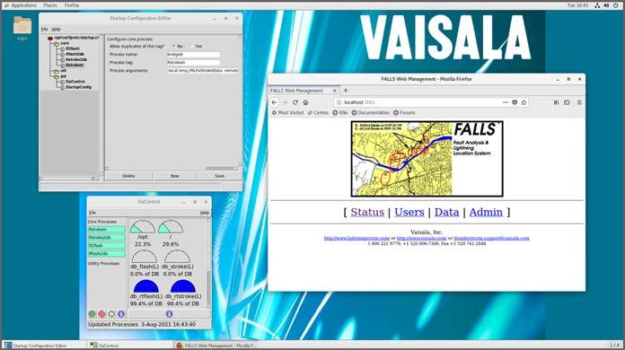
Computer hardware is subject to change. In case of evolution of an item, an equivalent or better item will be provided.
Simultaneous flash or total lightning and stroke data access support System compatibility Communication interfaces TCP/IP (recommended)
Operating humidity 20 … 80 %RH, non-condensing (non condensing twmax = +29 °C / +84 °F)
Technical data
Intelâ Xeonâ Silver 4208 or better CPU Operating system CentOS 8, 64 bit edition Memory 64 GB of RAM Hard disk space 4 × (960 GB) SSD SATA disk, RAID 5 RAID controller Hardware RAID controller that supports RAID 5 NIC ports Intelâ i350 Quad Port 1 GbE Base T, rNDC USB ports Min. 2 × USB 2.0 FP, 2 × USB 2.0 BP Optical disc drive DVD +/-RW, SATA, internal Monitor VGA, dual port, integrated Modem CentOS 8 compatible modem
Storage altitude −16 … 10 600 m (−50 … 35 000 ft)
Storage temperature −40 … +65 °C (−40 … +149 °F)
Storage humidity 5 … 95 %RH, non-condensing (non condensing twmax = +38 °C / +100 °F)
56
Operating environment
Operating temperature +10 … +35 °C (+50 … +95 °F)
Operating altitude −16 … 3048 m (−50 … 10 000 ft)
Minimum system requirements
Power requirements 100 … 240 V AC 47 … 63 Hz 0.4 kVA Data access/Output Scalable number of simultaneous users Supports simultaneous real-time and archived data access Access to archived data based on date/time, latitude/longitude, and range/ azimuth queries Base configuration supports on-line storage for 1 billion strokes or flashes
TLD100 and TLD200 module includes a reliable server with the following minimum Processorspecifications:
TLD100 and TLD200 support Archive lightning location data to Vaisala FALLS (TLD200 only) ODBC-compliant applications and other Vaisala FALLS server software (may require additional hardware)
www.vaisala.com
Inputs and outputs
Features
•Provides long-term storage of stroke and flash data in a relational database for poststorm and multi-year statistical
•Provides standard and customized lightning data format outputs that can be integrated with weather display software configured to ingest external data
•Provides a connection to Vaisala FALLSâ client software decision support system to analyze and display lightning activity
FALLSâ Server is a processing module in the Vaisala Thunderstorm Information System. It specializes in archiving cloud and cloud-to-ground lightning data for forensic applications, and connecting with FALLSâ Client application to display decision support information.
Easy, Secured Access to Realtime and Archived Lightning Information
•Supportsanalyses multiple workstations and simultaneous queries
57
•Manages multiple user connections, including accounting and security control functions with the capability to add users
FALLS Server is a lightning data management processor module that receives and stores real-time lightning data from Vaisala Thunderstorm central processor. Vaisala Thunderstorm Information System operators use the server to archive their lightning data into a relational database. Users have easy and secured access to the archived data for use in their lightning display software and lightning analysis software. The server also provides secured access to real-time lightning data. Flexibility for Users Multiple users can simultaneously access lightning information for use in their FALLS Fault Analysis and Lightning Location System, or custom lightning application software. The standard data format allows users to import lightning data into their weather display software that is configured to accept external FALLSdata. Server allows flexible and e cient manipulation of lightning data through a published set of industry standard Structured Query Language (SQL) function calls and procedures.
FALLS Server Fault Analysis and Lightning Location System
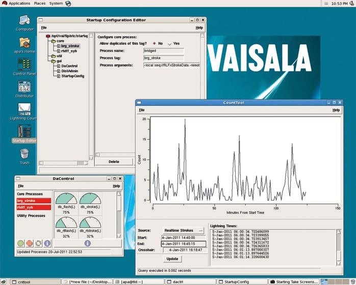
Data Access and Output
PostgreSQL has proven architecture that has earned a strong reputation for reliability, data integrity and correctness.
Scalable number of simultaneous users Supports simultaneous real-time and archived data access Access to archived data based on date/time, latitude/longitude, and range/ azimuth queries Base configuration supports on-line storage for 1 billion strokes or flashes
Internet connectivity is required for installation. Recommended speed: T1. Optical disc drive DVD+RW burner Modem RHEL6 or CentOS 6 compatible Form factor Tower or rack mount Processor 2 or more physical CPUs x86_64 compatible 2 GHz or Dual-corefasterorbetter Operating system Linux CentOS 6.x Memory Min. 64 GB RAM Hard disk space 4 or more internal hard drives, each 1 TB or larger RAID Min. 3 disks configured as RAID 5 1 disk as a hot spare to the RAID set Ports 2 or more USB 2.0 ports 2 NIC ethernet ports (100/1000 Mbps)
Technical Data Summary
Operating temperature +10 ... +35 °C (+50 ... +95 °F) Storage temperature -40 ... +65 °C (-40 ... +149 °F)
Power requirements 100 ... 240 VAC 47 ... 63 Hz 0.4 kVA Support Services
Simultaneous flash or total lightning and stroke data access support System Compatibility Communication interfaces Asynchronous RS-232 TCP/IP (recommended)
Operating altitude -16 ... 3048 m (-52 ft 6 in ... 10 000 ft) Storage altitude -16 ... 10 600 m (-52 ft 6 in ... 35 000 ft)
Computer hardware is subject to change. In case of evolution of an item, an equivalent or better item will be provided.
FALLSâ Server supports: •Archive lightning location data to Vaisala FALLSâ and Vaisala DAM analysis •Real-timesoftwaredatato other third-party •ASCII-based,software user-defined formats •Stored procedures and triggers •ODBC-compliant applications
Minimum System Requirements
Training and after-sales support services are available for maintaining optimal network and processor performance. Contact your Vaisala Sales Representative for service agreement information.
Operating Environment
FALLSâ Server resides on a single or multiprocessor server. It includes the Vaisala lightning database software license. FALLSâ Server utilizes a powerful, open-source, object-relational database system by PostgreSQL.
Storage humidity 5 ... 95 %RH, Non-condensingnon-condensingtwmax:+38 ºC (+100.4 °F)
Inputs and Outputs
The operating environment specifications are equal to the hardware specifications by default. The following specifications are subject to change without notice based on hardware availability.
Operating humidity 20 ... 80 %RH, (+84.2Non-condensingnon-condensingtwmax:+29ºC°F)
www.vaisala.com 58
•Execute other tasks while analyses run in the background
FALLS Lightning Data for your service territory (US and Canadian customers)
•The user can automate analyses by setting the start and end dates and by inserting other criteria
•Preferred discounts for real-time lightning data access with Vaisala’s partners Lightning Data Source North American customers have access to Vaisala U.S. National Lightning Detection Networkâ and the Canadian Lightning Detection Network, which together create the most comprehensive historic lightning database in the world. With a FALLS Server add-on, international customers and private Vaisala lightning detection network owners can access data from any Vaisala or archive processor. 59
•GIS (geographic information systems)
•FALLS Client and FALLS Server software support and upgrades
•Automaticallyfunctionalitygenerated maps save •Automatedtime processing of prioritized and queued analyses
Features
•Easy-to-use interface
FALLS Client Fault Analysis and Lightning Location System
Prioritize your analyses on the fly using FALLSâ Analysis queue. The ability to explore one analysis while others run in the background will improve your productivity.
•Easy interpretation of lightning data, using color, time, polarity and amplitude codes
•Filter out unwanted lightning data
Vaisala FALLSâ Client is innovative software used by electric utilities to query previously recorded lightning information in a GIS (Geographic Information Systems) environment.
FALLS Client generates lightning information into maps, graphs, and statistical tables, and is used to analyze the impact of lightning on assets and systems. Whether you are investigating suspected lightning-caused faults or are studying the climate of your service territory, Vaisala FALLSâ provides an easy-to-use platform to quantify and prioritize recommended protection investments Electric Utility Power Package Vaisala has now made it easier than ever for U.S. and Canadian customers, or international customers with access to a Vaisala precision lightning detection network, to gain access to the FALLS services you depend on to minimize the risk lightning poses to your operations. Partner with Vaisala for your historic and near real-time lightning data access, automated lightning fault correlation, and continuing education to keep your organization ahead of the Vaisalastorm.offers customers access to the following •Subscriptionoptions:toVaisala
•Priority access to the FALLS Users Group and Vaisala Webinars on special topics of interest
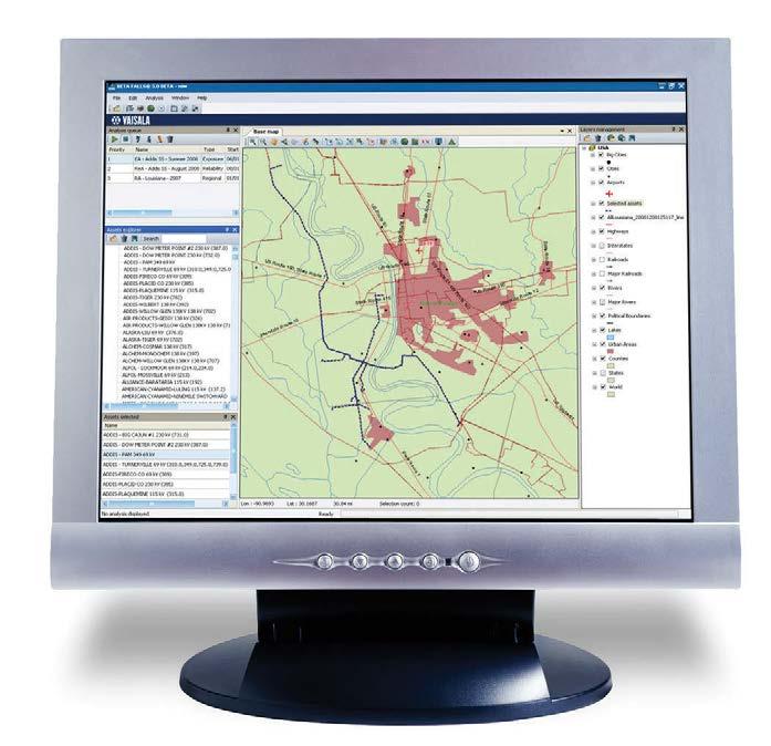
An example of FALLSâ Exposure Analysis for a transmission circuit in eastern Ohio. Areas of higher lightning activity are revealed. This information can help an electric utility to prioritize protection or maintenance.
FALLSâ Client Analyses
This FALLSâ Reliability Analysis reveals four cloud-toground lightning discharges which correlated to a suspected fault. The blue ellipse represents the stroke that best matches the fault recorder timestamp, and the red ellipse shows the highest peak current event. Field crews could be dispatched to the location to restore service.
FALLSâ allows the user to display and discriminate lightning discharges by their time of occurrence. The map displayed here for December 3rd and 4th, 2008 shows a line of thunderstorms in the U.S. gulf coast that tracked to the northeast.
60
An Exposure Analysis offers point-by-point and/or gridded analysis resolving the amount and type of lightning activity within user-defined asset buffer regions. It plots time trends of lightning over your service territory and/or assets, ranks assets by the amount and intensity of lightning exposure and discriminates by polarity and amplitude around user-defined asset buffers.
With a map of lightning density variations and percent positive discharges, it is used to identify hot spots for lightning activity, compare variations in lightning occurrence, amplitude, and polarity across days, weeks, months or years and statistically verify the expected amounts of lightning activity in your service territory.
Regional Analysis
Exposure Analysis
A Reliability Analysis maps event-specific lightning analysis in near real-time. It locates poorly performing line segments or system weaknesses, validates your lightning protection design and correlates your line faults to lightning activity or a lack of lightning activity.
Reliability Analysis
A Regional Analysis generates regional and local lightning strike occurrences and/or densities for user-specified time periods.
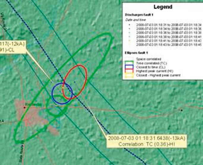
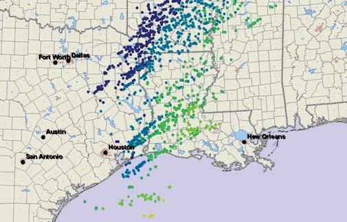
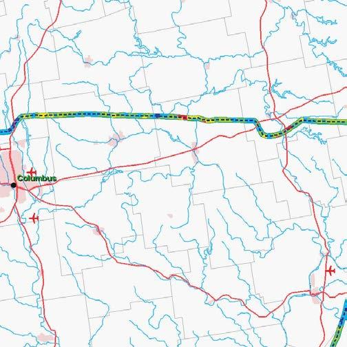
Processor 2.1+ GHz Intel Pentium 4, Intel Xeon, Intel Core Duo, or AMD Athlon equivalent Operating system Windowsâ 7 Pro Windowsâ 10 Memory Recommended: 2 GB RAM or higher Hard disk space 5 GB of available space: •850 MB for install •Up to 50 MB of disk space may be needed in the Windows System •3directoryGBofavailable space to be allocated for swap, temporary files, and saved analyses Display card 24-bit capable graphics accelerator card Screen resolution Recommended: 1280 × 1024, 32-bit Minimum: 1024 × 768, 32-bit Browser Recommended: Microsoftâ Internet Explorerâ 8.0 or higher Other DVD-ROM drive DVD is required to install FALLS, but not to run it www.vaisala.com
Technical Data Minimum System Requirements
61
•10 … 30 nmi (19 … 56 km)
The optical coincident requirement eliminates reporting of non-lightning TSS928events.
Superior performance in localarea lightning tracking
•Cloud and cloud-to-ground lightning within 30 nautical miles (56 km)
The patented lightning algorithms of TSS928 provide the most precise ranging of any standalone lightning sensor available in the world today.
Lightning-sensitive operations rely on Vaisala TSS928 sensors to provide critical local lightning information, both for meteorological applications as well as threat data, to facilitate advance warnings, initiate safety procedures, and isolate equipment with full confidence.
TSS928 Thunderstorm Local Lightning Sensor Features •Meets ASOS requirements for lightning range and bearing •Detects and reports range and bearing of cloud-to-ground •Detectslightningand counts cloud •Datalightningformat supports direct interface with •Self-diagnosticscommunicationcommonsystemsfeatures for checking sensor function status •Sustained performance in extreme weather conditions •Modular design allows easier field service and on-site maintenance
•Optical,detects:magnetic, and electrostatic pulses from lightning events with zero false alarms
•Cloud-to-ground lightning classified into directions: N, NE, E, SE, S, SW, W, and TSS928NWcan be used to integrate lightning reports with automated weather observation programs such as METAR. Vaisala TSS928™ accurately reports the range and direction of cloud-toground lightning and provides cloud lightning counts. 62
Vaisala TSS928™ is a local-area lightning detection sensor that can be integrated with automated surface weather observations.
• Cloud-to-ground lightning classified into three range intervals: •0 … 5 nmi (0 … 9 km) •5 … 10 nmi (9 … 19 km)
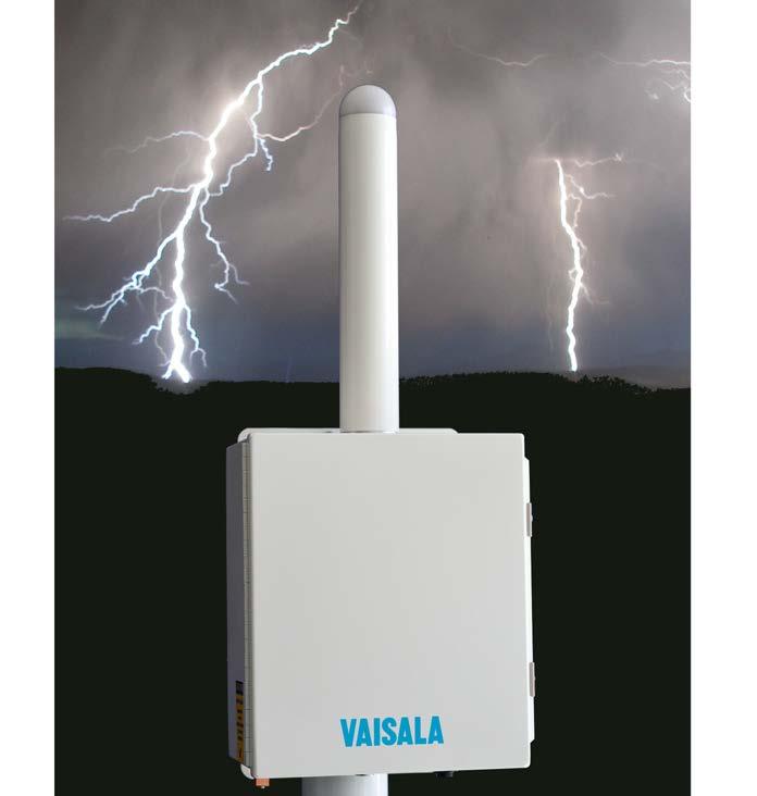

Operating environment
Bearing resolution One of eight compass octants (N, NE, E, SE, S, SW, W, NW)
Measurement performance
Relative humidity, operating 0 … 100 %RH Siting requirements Flexible installation requirements. Questions should be referred to your distributor or your Vaisala sales representative.
EMC immunity EN 61326 1, basic immunity test requirements EMC emissions CISPR 22 / EN 55022, Class B FCC part 15, class A ICES 3 (A) Electrical safety EN 61010 1 Compliance marks CE, China RoHS, FCC, RCM Mechanical specifications
Mounting options •Ground mount option •Roof mount option with tripod •Frame mount for either roof or ground options Height Max. 3 m (9 ft 10 in) recommended Weight (sensor only) 9.9 kg (22 lb)
Support services
Technical data
Compliance EU directives and regulations Low Voltage Directive (2006/95/EC) – 230 V model EMC Directive (2014/30/EU) RoHS Directive (2011/65/EU) amended by 2015/863
Detection range 30 nmi (56 km) radius from sensor location Range resolution Three range groups: •0 … 5 nmi (0 … 9 km) •5 … 10 nmi (9 … 19 km) •10 … 30 nmi (19 … 56 km)
The default TSS928 sensor messaging configuration is polled at user defined periods by external data acquisition equipment. The sensor may be configured to send present weather format messages at one minute intervals or immediately send flash format messages.
Detection efficiency Thunderstorm detection 98 % for thunderstorms within 10 nautical miles (12 mi, 19 km) with 3 or more cloud-to-ground discharges
Vaisala TSS928 is fully supported by our Customer Support Center, Technical Service Group, and Field Service Engineering Team. Maintain optimal performance by purchasing a service agreement customized to your unique system requirements.
Range resolution uncertainty 0 … 10 nmi (0 … 19 km): less than 3 nmi (5.6 km) 10 … 30 nmi (19 … 56 km): less than 6 nmi (11.1 km)
Sustained wind speed, maximum85 kn (157 km/h) (standard mast mount) Wind gust, maximum 125 kn (231 km/h)
Inputs and outputs DC power 11 … 32 V DC Power consumption Nominal 6 W Communications Serial ASCII format RS 232 and RS 422 serial at 9600 bps
Standard warranty Vaisala warrants all products manufactured by Vaisala to be free from defects in workmanship or material for 1 year from the date of delivery. Contact your Vaisala Sales Representative for specific product warranty and service warranty details. Dimensions www.vaisala.com 63
Operating temperature −40 … +60 °C (−40 … +140 °F) Storage temperature −40 … +60 °C (−40 … +140 °F)
Cloud-to-ground flashes Approximately 70 % for flashes within 10 nautical miles
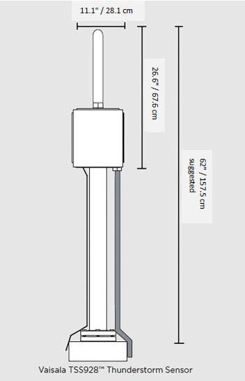
Features •Upper-air observation system for synoptic and adaptive use •All benefits of Vaisala Radiosonde RS41 and Vaisala MW41 Sounding •ReloadingSystem needed only once every four weeks •Safe working environment, gas lines located outside the •Ballooncontainerfilling with either hydrogen or helium •Remote control and configuration •Easy loading and stocking •Controlled access for improved operational safety •User interface design supports easier system diagnostics High-quality Data Complemented by Vaisala DigiCORAâ Sounding System MW41 and the RS41 radiosonde, Vaisala AUTOSONDE AS41 provides world class sounding data. Its automated and manual operations are based on proven algorithms and procedures, such as the automatic ground check.
As a reliable start reference for sounding data, AS41 uses either Vaisala Automatic Weather Station AWS310 installed on a 10 meter mast according to WMO requirements or Vaisala Weather Transmitter WXT536 installed on a short mast on the container roof.
Each individual detail in AS41 has been carefully designed and tested to achieve high target rates of successful soundings. AS41 is designed to endure extreme weather conditions around the world. Thoroughly tested automation control and carefully selected components and materials guarantee continuous operation with minimum downtime. f Cost Efficient Solution
AS41 offers the longest autonomous sounding capacity on the market. Site visits are significantly reduced as reloading is only required once every four weeks. As AS41 complies with tight international standards for explosive athmospheres, cost e cient hydrogen can be used as an optional balloon filling gas in place of helium. Easy Remote Control and Monitoring Vaisala Observation Network Manager NM10 is used for remote control and monitoring. Connecting to AS41 through a secure communication protocol, operators can e ciently control sounding schedules, initiate on demand soundings, and perform remote diagnostics.
High Data Availability
Vaisala AUTOSONDE AS41 is an upper-air observation system for synoptic and adaptive use. With a loading capacity of 60 radiosondes, it provides the longest autonomous sounding capacity on the market. 64
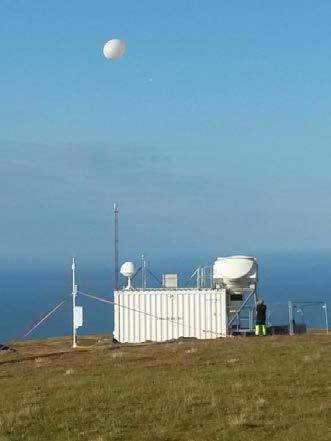
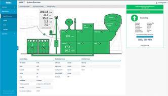
Vaisala Observation Network Manager software NM10 Preinstalled Operating system Windows 10 preinstalled System recovery tools Including USB drive with recovery image Electrical specifications Main electric cabinet Located inside the container Includes surge arresters, circuit breakers, residual current devices, mechanics controller, safety controller, servo drives, and frequency controllers. Mechanics controller Industry standard programmable logic controller with analog and digital I/O and electric motor controls. Input power 400 VAC 50 Hz 20 A, 3 phase 230 VAC 50 Hz 25 A, 1 phase Max. power consumption 5500 W Average power consumption Under 1000 W Cabling Halogen free Wall sockets Integrated in the operator desk Lights Ceiling light with presence detector Remotely controlled robotics room lights Heater 1000 W with thermostat Air conditioner with heating functionality 2000 W UPS Capacity for completing one ongoing sounding Mechanical specifications Container Dimensions during transportation (L × W × H) 6058 × 2438 × 2896 mm Transports as CSC-approved 20 feet HC sea container
Operating environment Operating temperature −40 °C ... +53 °C Operating humidity 0 … 100 %RH, condensing Max. operating wind speed 25 m/s Surviving wind speed 60 m/s Storage temperature −40 °C ... +53 °C Storage humidity 0 … 100 %RH, condensing Compliance Explosive atmospheres Part 14: Electrical installations design, selection and erection IEC 60079-14 (2013), IEC 60079-10-1 (2015) Machine safety Machinery Directive 2006/42/EC www.vaisala.com 65
Dimensions of access door with window (L × H) 900 × 2100 mm
Automatic Sounding Station Vaisala AUTOSONDEâ AS41 Loading capacity 60 radiosondes Storage capacity for consumables4 months (2 soundings a day) Radiosonde RS41-SG, RS41-SGP Sounding workstation •Sounding system software •Operatingpreinstalledsystem Windows 10 •AUTOSONDEpreinstalled Control software •Systempreinstalledrecovery tools, including USB drive with recovery image Vaisala Sounding Processing Subsystem SPS311G, SPS341AG Antennas Telementry antenna (directional UHF) GPS antenna Automatic ground check deviceRI41-AS41 Uninterrupted Power Supply Options for 1 hour and 3 hours Surface observation options •AWS310, sensors on separate 10 meter mast, complies with WMO CIMO guide 8 •WXT536, sensors on short mast attached to the container Remote server
Dimensions during operational use (L × W × H) 7800 × 3300 × 5100 mm
Technical data
Total weight with launcher vessel7.5 t Launcher vessel Vessel tube dimensions Ø 2 m Vessel frame material Acid proof steel frame Separate from the container Covers 2 pieces, operated by electric gearmotors Cover dimensions Ø 2 m, inside Cover material Laminated fiberglass Gas flow measurement Gas flow measurement unit •Installed on the container roof •2 flexible input gas hoses controlled by magnetic gas valves • Connection to gas regulator •Output hose to nozzle controlled by magnetic valves Gas flow meter With electrical current output Maintenance-free, no moving parts Automatic measurement of gas amount Balloon Balloon size 200 … 1200 g Balloon filling gas Hydrogen or helium Nozzle Connected to the balloon during Gas-proofloading connection Container outdoor painting color codes White RAL9003 Gray (for the container access door)RAL7035 Container painting color types for outdoors First coating Interzinc 52 Second coating Intergard 475HS Interseal 1052 Third coating Interthane 990SG
During a sounding, data can be visualized in a variety of views like graphs, tables and a map. With DigiCORA as a guide, preparing a radiosonde continues to require minimal effort from the user. Configuring DigiCORA to create a wide range of meteorological messages is easy. Triggers and messages set for the sounding are displayed in a brand-new flight plan layout, which shows the main sounding events relative to the current sounding status.
Vaisala Cirrusâ Sounding System MW51 is the foundation of modern meteorological upper air observations. Excellent radio characteristics
The new built-for-purpose Vaisala Cirrusâ Sounding Processing Subsystem SPS511 is sensitive to radiosonde signals, while also being resistant to interference near the meteorological frequency band. This allows for a steady data flow from the radiosonde to the MW51 system, resulting in an accurate atmospheric profile even in demanding radio environments. Sustainable IT security
Compact and portable Variable field conditions and locations for research campaigns pose demands on the sounding system, which needs to be portable as well as e ciently built for transport. MW51 continues to support the portable antenna set CG31 with both UHF and GPS antennas, and SPS511 is notably smaller and lighter than its predecessor.
Vaisala Cirrus Sounding System MW51 processes, analyses, archives, and relays sounding data. While keeping the best qualities of its predecessor MW41, it introduces significant improvements to radio design, usability, and reliability.
New, intuitive and visual DigiCORA Software
The system is designed with security in mind. User access is controlled, while data transfer and remote control use secure Regularcommunication.securityupdates are available for both the DigiCORA application software as well as the embedded SPS511 firmware. This provides the user with additional peace of mind against IT security threats.
MW51 Cirrus Sounding System Features •Consistent, high quality data •Easy to operate •Good tolerance to near-band •Longinterferencetelemetry range •Inbuilt IT security with regular •Compactupdates design supports portable applications
The MW51 system consists of a computer that runs DigiCORAâ Software, the Sounding Processing Subsystem SPS511, the RI41 / RI41 B Ground Check Devices for preparing RS41 radiosondes, and the UHF and GPS antennas used to receive the radiosonde signal and provide local positioning data. Together with RS41, the MW51 system brings upper air measurements into a new era. To ensure the system meets the needs of a wide range of Vaisala Radiosonde RS41 customers, various radiosonde ground check device and antenna options are available. If desired, the DigiCORA user interface can be accessed from anywhere within the connected network using a standard web browser. With an IP rating of IP54, SPS511 tolerates dust and moisture well. SPS511 uses conductive cooling and has no moving parts. The electronics are designed on one signal board to minimize points of failure. 66
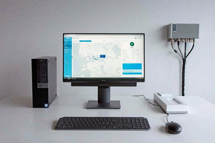
USB port For connecting the ground check device Serial port For optional future connection of Automatic Weather Station. Either integrated serial port or via USB / RS 232 converter Network adapter For connecting the sounding processing subsystem Speakers For audio notification (optional)
Operating environment Computer and accessories Operating temperature +10 … +40 °C (+50 … +104 °F) +10 … +45 °C (+50 … +113 °F) with rugged laptop Storage temperature −40 … +65 °C (−40 … +149 °F) Operating humidity 10 … 90 %RH Storage humidity 5 … 95 %RH Sounding Processing Subsystem SPS511
Operating temperature 0 … +45 °C (+32 … +113 °F) Storage temperature −40 … +65 °C (−40 … +149 °F) Operating humidity 5 … 100 (condensing)%RH IP rating IP54 Ground check devices RI41 and RI41 B. See separate datasheets for details. Antennas RB31, RM32, RM31N, CG31 and GA31 or GA31N. See separate datasheets for details. Meteorological messages BUFR messages BUFR 3’09’050 and BUFR 3’09’051 (for PILOT data) BUFR 3’09’052 and BUFR 3’09’057 (for TEMP data) BUFR 3’09’053 and BUFR 3’09’056 (for descending sounding after balloon burst) All BUFR messages are also available as high resolution variants. TEMP messages TEMP FM35-XI Future DigiCORA releases will have enhanced compatibility with other Vaisala products, as well as more available features and meteorological messages. www.vaisala.com
67
Ground check devices • RI41 • RI41 B with barometer module Antennas •Vaisala Directional UHF Antenna •OmnidirectionalRB31 UHF antennas RM32 and RM31N •Vaisala GPS Antenna GA31/N • Vaisala portable (UHF + GPS) antenna set CG31
Operating system Windows 10 Pro 64-bit (English)
Radiosondes •RS41 SG • RS41 SGP Sounding processing subsystemsVaisala Cirrus Sounding Processing Subsystem SPS511 Application software DigiCORAâ Software
Technical data Performance
Minimum system requirements for sounding workstation
Web browser •Microsoft Edgeâ latest version •Mozilla Firefoxâ latest version •Google Chrome™ latest version Processor Intel Pentium Dual Core or equivalent (Quad Core recommended)
Memory 8 GB RAM (16 GB RAM recommended) Hard disk space 160 GB Display resolution 1366 × 768 (Full HD, 1920 × 1080 recommended)
Range with Directional antenna RB31Up to 350 km (217.5 mi) Range with Omnidirectional antenna RM32 200 km (124 mi) Range with Omnidirectional antennas CG31 and RM31N 150 km (93mi) System components and compatible radiosondes
Quick to configure Configuring DigiCORA for operation is easy. The user interface supports quick configuration of station parameters, message creation, and parameter sending. The system can also be configured remotely. DigiCORA validates sounding data to ensure it is of high quality. The system can create various WMO messages. 68
Vaisala Sounding System MW41 processes, analyses, archives, and relays sounding data. The system consists of a computer that runs DigiCORA, and is connected to a sounding processing subsystem using a network adapter.
f Features •Modern look and feel •Consistent, high quality data •Easy integration to existing soundings network •Increased flexibility through advanced networking options •Easy and intuitive operation •Quick configuration and modification of station parameters, also remotely
Vaisala Sounding System MW41 is now available with the new DigiCORA Software application that supports the world-class performance of the Vaisala RS41 radiosonde family. This makes MW41 an excellent choice for both synoptical and research applications.
DigiCORA consists of the user interface running on a web browser and the sounding processing software running as services on a computer. Flexible to use As the DigiCORA user interface runs on a web browser, it can be operated from anywhere. This allows, for example, managing sounding operations remotely, away from the sounding station. Additionally, all network users can access sounding data remotely.
Intuitive to operate DigiCORA guides you through the radiosonde preparation process with a minimal need for user input and interaction. Clear status indicators and animations tell you whenever action is needed. As operating the system is highly intuitive, training users is faster. Access to specific functionalities can be defined with user groups and their related privileges.
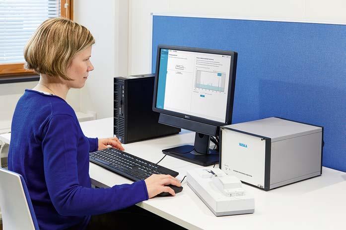

Technical data
Minimum system requirements for sounding workstation
Software defined radio technology Code correlating GPS Operating environment Computer and accessories Operating temperature +10 … +40 °C (+50 … +104 °F) +10 … +45 °C (+50 … +113 °F) with rugged laptop Storage temperature −40 … +65 °C (−40 … +149 °F)
Tuning step (user-adjustable) 10 kHz Error detection and correctionReed-Solomon Telemetry range (using directional antenna) Up to 350 km (217.5 mi)
Radiosonde compatibility Radiosonde RS41-SGPRS41-SG
USB port For connecting the ground check device Serial port For optional future connection of Automatic Weather Station. Either integrated serial port or using USB / RS 232 converter Network adapter For connecting the sounding processing subsystem Speakers For audio notification (optional)
Operating humidity 10 … 90 %RH Storage humidity 5 … 95 %RH Sounding Processing Subsystem SPS311G / SPS341AG Operating temperature 0 ... + 45 °C (+32 … +113 °F) Storage temperature −55 ... + 70 °C (−67 … +158 °F)
Meteorological messages messagesBUFR BUFR 3’09’050 and BUFR 3’09’051 (for PILOT data) BUFR 3’09’052 and BUFR 3’09’057 (for TEMP data) BUFR 3’09’053 and BUFR 3’09’056 (for descending sounding after balloon burst)
Operating humidity 10 … 90 %RH (non-condensing) Storage humidity 5 … 95 %RH Altitude Up to 2 000 m (6 562 ft)
Recommended frequency difference between sondes used simultaneously 150 kHz
All BUFR messages are also available as high resolution variants. Antennas Directional UHF antenna (automatic direction control) RB31 Omnidirectional UHF antenna RM31NRM32 Portable antenna for UHF and GPSCG31 GPS antenna GA31NGA31
Vaisala Sounding Processing Subsystem
Web browser •Microsoft Edgeâ latest version • Mozilla Firefoxâ latest version •Google Chrome latest version Processor Intel Pentium Dual Core or equivalent (Quad Core recommended) Memory 8 GB RAM (16 GB RAM recommended) Hard disk space 160 GB Display resolution 1366 × 768 (Full HD, 1920 × 1080 recommended)
Operating system Windows 10 Pro 64-bit (English)
Ground check devices RI41 and RI41 B. See separate datasheets for details. Future DigiCORA releases will have enhanced compatibility with other Vaisala products, as well as more available features and meteorological messages. www.vaisala.com 69
The operating environment requirements may vary depending on different product models. Telemetry Frequency band 400.15 … 405.99 MHz
Ground check devices RI41 and RI41 B. See separate datasheets for details. Antennas RB31, RM32, RM31N, CG31 and GA31 or GA31N. See separate datasheets for details.
Features •Consistent, high quality data •Easy integration to existing soundings network •Increased flexibility through advanced networking options •Easy and simple operation •Quick configuration and modification of station parameters, also remotely
Vaisala Sounding System MW41 processes, analyses, archives, and relays sounding data. The system consists of a computer that runs MW41 sounding software and is connected to a sounding processing subsystem via a network adapter. MW41 sounding software includes the sounding processing software running as services on a computer and an optional remote client for remote access/use. Easy to integrate Upgrading to MW41 from earlier Vaisala sounding systems is smooth and cost effective. The software is compatible with commonly used Windows operating systems and hardware, making it easy to integrate to most IT bases and helping to minimize maintenance costs. Connectivity with Vaisala Automatic Weather Stations allows using highly accurate surface weather information as reference, which makes operation simpler and less sensitive to human error. Flexible to use As MW41 user interface is separated from other software functionalities, it can be operated from anywhere within your network. This allows, for example, managing sounding operations remotely, away from the sounding station. Additionally, all network users can access sounding data, remotely.
Quick to configure Configuring MW41 for operation is easy. The user interface supports quick configuration of station parameters, message creation, and parameter sending. The system can also be configured remotely. MW41 validates sounding data to make sure it is of high quality. The system can create WMO messages and special text reports using the validated data, and the data is also available in XML format. 70
Vaisala Sounding System MW41 supports the world-class performance of Vaisala RS41 radiosonde family. This makes MW41 an excellent choice for both synoptical and research applications.
The standard MW41 software package includes all features needed to perform synoptic soundings. For more advanced sounding needs, like ozone sounding capability or extended graphics, optional modules are available. The system can be tailored for specific needs of a sounding station. Intuitive to operate MW41 follows the radiosonde preparation process, minimizing the need for user input and interaction. When the user needs to act, using the system is made easier with clear status indicators and animations, and a software help is available for additional assistance. As operating the system is highly intuitive, training users is faster. Access to specific functionalities can be defined by utilizing user groups and their related privileges.
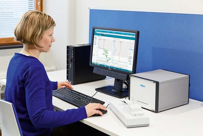
Speakers Integrated either into computer or display Remote client PC Using devices that fulfill the same requirements as for Sounding Workstations is recommended.1)
1) It is likely that devices with lower hardware specifications, other operating systems, or other browsers can be used.
Optional serial ports Either integrated or using USB/ RS 232 converter. 1 for possible Automatic Weather Station USB port For connecting the ground check device Ethernet adapter For isolating the sounding system from the internal network
Advanced option CLIMAT TEMP FM 75-X BUFR 3’09’053 (DROP BUFR)
Meteorological messages
Minimum system requirements for sounding workstation
Computer PC delivered by Vaisala includes: • Pre installed MW41 sounding software • System recovery tools, including USB drive with recovery image •Optional Edgeport serial extension Optionally, any PC that fulfills the requirements below can be used.
Operating system •Windowsâ 11 Pro •Windowsâ10 Pro 64-bit Web browser • Microsoft Edge latest version
TEMP messages TEMP FM35-XI, TEMP SHIP FM36-XI, TEMP MOBIL FM38-XI
PILOT messages PILOT FM32-XI, PILOT SHIP FM33-XI, PILOT MOBIL FM34-XI BUFR messages BUFR 3’09’050 and BUFR 3’09’051 (for PILOT and High resolution data) BUFR 3’09’052 and BUFR 3’09’057 (for TEMP and High resolution data) BUFR 3’09’056 (for descending sounding after balloon burst)
Technical data Compatibility Radiosonde •RS4•RS41-SGM•RS41-SGP•RS41-SG1-D Special sensor Ozone •Z•ECCsensors:6AECCECC
Memory 8 GB RAM Hard disk space 160 GB Display resolution 1366 × 768 (minimum)
Software defined radio technology Code correlating GPS Operating environment Indoor equipment Operating temperature +10 … +40 °C (+50 … +104 °F) +10 … +45 °C (+50 … +113 °F) with rugged laptop Storage temperature −40 … +65 °C (−40 … +149 °F) Operating humidity 10 … 90 %RH Storage humidity 5 … 95 %RH Outdoor equipment Operating temperature −40 … +55 °C (−40 … +131 °F) Storage temperature −50 … +71 °C (−58 … +160 °F) Operating humidity 0 … 100 %RH Storage humidity 0 … 100 %RH Operating wind speed 0 … 65 m/s (0 … 145 mph) Operating precipitation Unlimited Telemetry Frequency band 400.15 … 406 MHz
Tuning step (user-adjustable) 10 kHz Error detection and correctionReed-Solomon Telemetry range (using directional antenna) Up to 350 km (217.5 mi)
Special sensor option NILU, WOUDC Defense messages option METCM STANAG 4082, METB2/ METB3 STANAG 4061, METFM STANAG 2103, METSR/METSRX, METTA STANAG 4140, METEO 11
•Mozilla(English)Firefox latest version (English) • Google Chrome latest version (English) Processor Intel Pentium Dual Core or equivalent (Quad Core recommended)
Antennas
Directional UHF antenna (automatic direction control)
Omnidirectional UHF antenna Portable antenna for UHF and GPS GPS AdvancedantennaMultipath Rejection GPS antenna Ground check set RI41 and RI41 B. See separate datasheets for details. www.vaisala.com 71
DVD-ROM drive For the installation media
Vaisala Sounding Processing Subsystem
MW32 is a fully rugged sounding system designed and specified for tough military use. Di erent configurations include a portable system, vehicle installation, and naval installation.
Easy operation
Rugged design for tough military use
Vaisala MARWINâ Sounding System
72
The system can be operated, assembled, and disassembled wearing gloves or arctic mittens.
•Ruggedmodels design to stand harsh environment and transport
•Meteorological profile data for artillery ballistic preparation, naval applications, fire weather, and numerical weather prediction
MW32 provides an atmospheric profile of wind, pressure, temperature, and humidity from the surface up to the altitudes to be used in the ballistic weather computation. The data can be used as input into numerical weather models to provide updated observation for more precise predictions. The atmospheric profile is useful e.g. for fire weather, aviation, CBRN, and naval Withapplications.VaisalaRadiosonde RS41 SGM, encryption and radio silence (patent EP2689279, Method for launching and a radiosonde) improve security of defense operations. Radiosonde transmission does not reveal the balloon launch location because the radiosonde transmitter is not switched on until a specified height or time from launch has been reached. Data is recorded also during the radio silence and, when the radio silence ends, transmitted to MW32.
•Straight forward, menu-driven operation through integrated display and keyboard
Versatile interfaces
Vaisala MARWINâ Sounding System
The MW32 system provides one integral LAN port, two USB ports and four serial ports. It also supports the PCSERV protocol of the Vaisala MARWINâ Sounding System MW12 legacy so the MW32 can replace the MW12.
Compact system design
The MW32 system consists of a receiver/ processor and antennas to track the radiosonde attached to a freeflying balloon. The integrated display and keyboard unit supports menu driven operation. Side panel connectors enable rack mount installation. The display unit and connector panel have been designed using MIL STD 1472F as a guideline.
•Extensive data quality assurance processes guarantee error free messages in relevant STANAG and WMO formats
•With Vaisala Radiosonde RS41 SGM, improved security thanks to radio silence (patent EP2689279, Method for launching and a radiosonde) and encryption
The MW32 system is straightforward to operate using the self-guiding menu. After powering-up, the radiosonde is connected to the system for setting-up using a ground check device. When done, the system indicates its readiness for launch.
The MW32 system has been designed from conception for demanding use in harsh environments, and rough transportation. A special feature is the conductive cooling. MW32 complies with MIL STD 810G for vibration, functional shock and transit drop, low and high temperature, temperature shock, sand and dust, wind driven rain, humidity, salt fog, and altitude.
MW32 MARWIN Sounding System Features
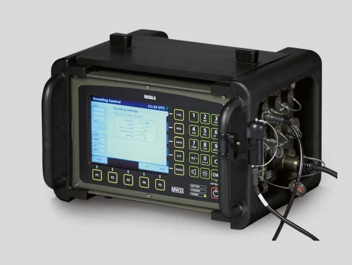
METEO 11 Meteorological messages (WMO)
1)Required configuration if 1680 MHz band RS41-D or RS92-D is used
Power supply Internal AC power unit Input: 90-132 / 180-264 VAC 4autoranging,763Hz,180 W max Internal DC power unit Input: 18-33 VDC, 144 W max., MIL STD 1275B DC out for external device: 12 V / 0.5 A, 28 V / 1 A Internal battery 2 pcs, Ultralife UBBL02 01 Li-Ion Internal back-up power time: 240 Batteryminutes.pack capacity: 2 × 250 Wh Automatic switch-over from AC to external DC to internal battery
Storage humidity 0 ... 100 %RH
Vaisala Radiotheodolite RT20A 1)
Meteorological messages (military)
METCM, STANAG 4082 Standard Artillery Computer Meteorological Message METB2/METB3, STANAG 4061Standard Ballistic Meteorological Message METFM, STANAG 2103 Standard Fallout Meteorological Message
Operating humidity 0 ... 100 %RH Storage temperature (without batteries) 40 ... +71 °C (-40 ... +159.8 °F) Storage humidity 5 ... 95 %RH Antennas Operating temperature -40 ... +55 °C (-40 ... +131 °F)
Frequency range 400.15 ... 406 MHz, EN 302 054 v1.1.1 1668.4 1)… 1690 MHz EN 302 454 v1.1.1 Tuning step 10 kHz, user adjustable Error detection and correctionReed-Solomon Telemetry range (400 MHz) 150 km (93.2 mi) with portable/ vehicle antennas and up to 350 km (217.5 mi) with directional antenna
Operating precipitation Unlimited Storage temperature 50 ... +71 °C (-58 ... +159.8 °F)
Supported Vaisala radiosondesRS41 SGM, RS41 SGP, RS41 SG, RS41 D, RS92 AM, RS92 SGP, and RS92 D Windfinding options C/A code Radio-directionGPS finding (with Vaisala Radiotheodolite RT20A) 1)
Radiosondes and windfinding options
METSR/METSRX Sound Ranging Meteorological Message METTA, STANAG 4140 Standard Target Acquisition Meteorological Message
www.vaisala.com 73
Technical Data Hardware and software Processor type COM Express PC, 1.5 GHz DRAM SO-DIMM, 2 GB Flash disk 8 GB TFT LCD display 8.4 in, SVGA, transflective, daylight viewable
Operating humidity 0 ... 100 % Operating wind speed 0 ... 65 m/s (0 ... 145 mph)
1)Required configuration if 1680 MHz band RS41-D or RS92-D is used
Antennas CG31 Portable antenna (UHF and GPS) CG32 Vehicle antenna (UHF and GPS) RM32 and RM31N, Omnidirectional UHF antennas GA31 and GA31N, GPS antennas RB31 Directional UHF antenna for fixed installation
Telemetry
TEMP FM35-XI, TEMP SHIP FM36-XI, TEMP MOBIL FM38-XI PILOT FM32-XI, PILOT SHIP FM33-XI, PILOT MOBIL FM34-XI BUFR 3’09’050, BUFR 3’09’051 for PILOT data, BUFR 3’09’052 for TEMP data, and BUFR 3’09’053 for a descending sounding with RS41 series GPS radiosondes
1)Required configuration if 1680 MHz band RS41-D or RS92-D is used
Integral console 5 hardkeys, 5 softkeys, alphanumeric keypad Operating system Windows Embedded Standard 2009 I/O ports Asynchronous serial RS-232C, 4 lines LAN connection 10/100 Mbps Ethernet, 1 line USB USB1.1 / USB2.0, 2 lines Other Cooling system Conductive cooling, no cooling fans Case Cast aluminum Connector types MIL-C-26482, MIL-C-38999, MIL C 5015 Protection class IP65 Environmental tests MIL-STD-810G, see separate list Electromagnetic compliance MIL-STD-461F, see separate list Dimensions (H × W × D) 280 × 430 × 380 mm (11.02 × 16.93 × 14.96 in) Weight 22 kg (48.50 lb) Overvoltage category II Pollution degree 2 Maximum operating altitude 3000 m (approx. 9800 ft)
Operating environment Operating temperature -20 ... +50 °C (-4 ... +122 °F)
The pressure sensor is the same highquality, shock-resistant capacitive silicon sensor as the one in the Vaisala Radiosonde RS92 with revised electronics and calibration. All RS41 sensors are calibrated against references that are traceable to international standards (SI units) and measurement uncertainties are estimated according to recommendations of the Joint Committee for Guides in Metrology, 100:2008.
RS41-D PTU Sensors
Vaisala Radiosonde RS41-D – accuracy and reliability with Vaisala Radiotheodolite RT20 systems.
RS41-D Radiosonde Features •Independent and passive windfinding with Vaisala Radiotheodolite RT20 systems • Superior PTU measurement •Automatedperformanceground check •Robust and easy-to-use design with informative LEDs •Stable narrow-band transmission complies with ETSI standard EN 302 •Unwinder454 for consistent sensor boom positioning Independent and Passive Windfinding Vaisala Radiosonde RS41-D is the RS41 radiosonde model for Vaisala Radiotheodolite RT20 systems. RS41-D measures pressure, temperature and humidity, and RT20 provides a passive and independent windfinding solution.
Carrying out Ground Checks on RS41 Radiosonde RS41 ground check includes several functional checks: temperature check, humidity sensor recondition, humidity check and setting radiosonde parameters. Ground check is performed prior to flight for a radiosonde placed on the Ground Check Device MWH322/RI41 conveniently operated with MW32/ MW41 software.
Vaisala Radiosonde RS41 temperature sensor utilizes linear resistive platinum technology known for its high stability.
The small size of the sensor results in low solar radiation error and guarantees fast response. It also incorporates effective protection against evaporating cooling, a phenomenon occasionally encountered when a radiosonde emerges from a cloud top. The humidity sensor integrates humidity and temperature sensing elements. Preflight automatic reconditioning of the humidity sensor effectively removes chemical contaminants and ensures excellent humidity measurement accuracy. The integrated temperature sensor is used to compensate the effects of solar radiation in real time. The sensor heating function enables an active and effective de-icing method at freezing conditions during the flight. The humidity sensor also responds quickly to detect fine structures of the atmosphere.
Short range wireless communication link is used in ground check devices for turning radiosonde power on and for data transfer during the ground check. The communication link is based on the RF technique within the range around 4 Forcm. the pressure measurement ground check, the sounding software compares pressure sensor reading difference against an optional barometer module installed inside the ground check device, and adjusts the measurement accordingly. Alternatively an external precision barometer can be used as the reference value and the readings entered manually.
74
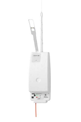
Unwinder Material of the string Non-UV treated polypropylene Tenacity < 115 N Length of the string 55 m Unwinding speed 0.35 m/s Weight 25 g Measurement performance data is expressed with 2-sigma confidence level (k=2), unless otherwise explicitly specified. For humidity, the performance data is valid T > −60 °C www.vaisala.com
2) Standard deviation of differences in twin soundings, ascent rate above 3 m/s for temperature and humidity Telemetry
Technical data Measurements
Measurement cycle 1 s Temperature sensor Type: Platinum resistor Measurement range +60 °C to −95 °C Resolution 0.01 °C Response time (63.2%, 6 m/s flow, 1000 hPa)1) 0.5 s Stability 1 year / 3 years < 0 05 °C / < 0.1 °C RepeatabilityAccuracy: in calibration 0.1 °C Combined uncertainty after ground preparation0.2 °C Combined uncertainty in sounding < 16 km0.3 °C Combined uncertainty in sounding > 16 km0.5 °C Reproducibility in sounding 2) > 100 hPa 0.15 °C < 100 hPa 0.30 °C Humidity sensor Type: Thin-film capacitor Measurement range 0 to 100 %RH Resolution 0.1 %RH Response time 6 m/s, 1000 hPa, +20 °C < 0.3 s 6 m/s, 1000 hPa, −40 °C < 10 s RepeatabilityAccuracy: in calibration 2 %RH Combined uncertainty after ground preparation3 %RH Combined uncertainty in sounding 4 %RH Reproducibility in sounding2) 2 %RH Pressure Type: Silicon capacitor Measurement range from surface pressure to 3 hPa Resolution 0.01 hPa RepeatabilityAccuracy: in calibration > 100 hPa 0.4 hPa 100 - 3 hPa 0.3 hPa
75
Environmental tests (transit drop, vibration) MIL-STD-810G
Compatibility With Vaisala Radiotheodolite RT20 systems Transmitter type Synthesized Frequency band 1668.4 MHz - 1690 MHz Tuning range 1668.6 - 1689.8 MHz Maximum transmitting range up to 160 km Emission bandwidth According to EN 302 454 Output power (high-power mode)200 mW, typical Sideband radiation According to EN 302 454 Modulation GFSK Frequency setting Wireless with ground check device Operational data Power-up Wireless with ground check device or with switch Factory calibration Stored on Flash memory Battery 2 pcs AA-size Lithium cells Operating time > 135 min Weight 84 g Dimensions1) Body (L × W × H): 155 × 63 × 46 mm Sensor boom bent (L × W × H): 282 × 63 × 104 mm
Combined uncertainty in sounding > 100 hPa 1.0 hPa 100 - 3 hPa 0.6 hPa Reproducibility in sounding2) > 100 hPa 0.5 hPa 100 - 3 hPa 0.3 hPa 1)After applying time-lag correction, the effect to measurement uncertainty is negligible.
1)For cover; without wire antenna
RS41-SG Radiosonde Features •Superior PTU measurement •Automatedperformanceground check • Robust and easy to use design with informative LEDs •GPS for continuous wind data availability as well as height and pressure calculation •Stable narrow band transmission complies with ETSI standard EN 302 054
Vaisala Radiosonde RS41 temperature sensor is very stable, utilizing linear resistive platinum technology. The small size of the sensor results in low solar radiation error and guarantees fast response. The RS41 temperature sensor also incorporates effective protection against evaporating cooling, the phenomenon occasionally encountered when a radiosonde emerges from a cloud top. RS41 humidity sensor integrates humidity and temperature sensing elements to provide unique features. Prior to flight, automatic recondition of the humidity sensor effectively removes chemical contaminants and ensures excellent humidity measurement accuracy. Integrated temperature sensor is used to compensate the effects of solar radiation in real time resulting in very precise measurement. The sensor heating function enables an active and effective de-icing method when a radiosonde is flying through layers with freezing conditions. The humidity sensor is very accurate throughout the whole measurement range and has fast response to detect fine structures of the atmosphere.
Unwinder With the unwinder the radiosonde sensor boom is automatically set in an ideal position for sounding. As the unwinder is separated from the radiosonde, the balloon and unwinder can be prepared in advance to streamline launch preparations.
Data Transmission RS41-SG has proven data transmission from radiosonde to receiver up to 350 km. This is su cient for any sounding operations. Data availability during a sounding is guaranteed with digital error correction code transmission and telemetry errors are always detected. Due to narrow band transmission, more channels are available in the meteorological frequency band.
Add-on Sensor Connector RS41 has a serial interface for additional sensors, primarily to connect ozone interface OIF411 to RS41. Also other sensors with Xdata protocol can be connected. The data is transferred either directly or via OIF411 to a RS41 radiosonde and further to Vaisala DigiCORAâ Sounding System MW41.
76
Temperature and Humidity Sensors
RS41 Ground Check RS41 ground check includes several functional checks: temperature check, humidity sensor recondition, humidity check and setting radiosonde parameters. Ground check is performed prior to flight on a radiosonde placed on the Ground Check Device RI41 conveniently operated with MW41 software. Wind Data, Height and Pressure Wind, height and pressure are derived from velocity and location measurements of the RS41 GPS receiver. Height and pressure are calculated from satellite ranging codes, combined with differential corrections from the MW41 ground station. Pressure calculation also uses temperature and humidity from the radiosonde. Wind is calculated independently based on satellite carrier frequency changes.
Vaisala Radiosonde RS41-SG – accuracy and reliability.
RS41 Calibration RS41 temperature and humidity sensors are calibrated against the references that are traceable to SI standards and measurement uncertainties are estimated according to recommendations of Joint Committee for Guides in Metrology, 100:2008.
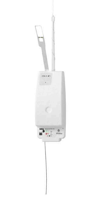
Measurement cycle 1 s Temperature Sensor Type: Platinum Resistor Measurement range +60 °C to −95 °C Resolution 0.01 °C Response time (63.2%, 6 m/s flow, 1000 hPa)1) 0.5 s Stability (1 year / 3 years) < 0 05 °C / < 0.1 °C RepeatabilityAccuracy: in calibration 0.1 °C Combined uncertainty after ground preparation0.2 °C Combined uncertainty in sounding < 16 km0.3 °C Combined uncertainty in sounding > 16 km0.4 °C Reproducibility in sounding 2) > 100 hPa 0.15 °C < 100 hPa 0.30 °C Humidity Sensor Type: Thin-Film Capacitor Measurement range 0 to 100 %RH Resolution 0.1 %RH Response time: 6 m/s, 1000 hPa, +20 °C < 0.3 s 6 m/s, 1000 hPa, −40 °C < 10 s RepeatabilityAccuracy: in calibration 2 %RH Combined uncertainty after ground preparation3 %RH Combined uncertainty in sounding 4 %RH Reproducibility in sounding 2) 2 %RH Pressure Type: Calculated from GPS Measurement range From surface pressure to 3 hPa Resolution 0.01 hPa CAccuracy:ombined uncertainty / Reproducibility in sounding 2) > 100 hPa 1.0 hPa / 0.5 hPa 100 - 10 hPa 0.3 hPa / 0.2 hPa < 10 hPa 0.04 hPa / 0.04 hPa Geopotential Height Type: Calculated from GPS Measurement range 3) From surface to 40 000 m Resolution 0.1 gpm
Telemetry
Number of channels ≥ 48 Frequency 1575.42 mHz, L1 C/A code Cold start Acquisition Time 35 s (nominal)
Material of the string Non-UV treated polypropylene Tenacity <115 N Length of the string 55 m Unwinding speed 0.35 m/s Weight 25 g
1)After applying time-lag correction, the effect to measurement uncertainty is negligible. 2)Standard deviation of differences in twin soundings, ascent rate above 3 m/s
Add-On Sensor Support Protocol support Xdata to connect several sensors in the same chain, data transferred either directly or via OIF411 to RS41 Transfer rate Max. 200 bytes/s Unwinder
3)In practice unlimited 4)Standard deviation of differences in twin soundings. Wind speed above 3 m/s for directional measurement uncertainty.
77
1)For cover; without wire antenna
CombinedAccuracy: uncertainty in sounding 10.0 gpm Reproducibility in sounding 2) 6.0 gpm Wind Speed Velocity measurement uncertainty 4) 0.15 m/s Resolution 0.1 m/s Maximum reported wind speed 3) 180 m/s Wind Direction Directional measurement uncertainty 4) 2 deg Resolution 0.1 deg Wind direction range 0 to 360 deg
Technical Data Measurements
Transmitter type Synthesized Frequency band 400.15 – 406 MHz Tuning range 400.16 – 405.99 MHz Maximum transmitting range Up to 350 km Frequency stability, 90 % probability±2 kHz Deviation, peak-to-peak 4.8 kHz Emission bandwidth According to EN 302 054 Output power (high-power mode)Min. 60 mW Sideband radiation According to EN 302 054 Modulation GFSK Data downlink 4800 bit/s Frequency setting Wireless with ground check device GPS Receiver (SA Off, PDOP<4)
Reacquisition Time 1 s (nominal)
The performance data is expressed with 2-sigma confidence level (k=2), unless otherwise explicitly specified. For humidity, the performance data is valid T > -60 °C. www.vaisala.com
Correction Differential Reporting resolution of lat, lon position values 1e-8° Operational Data Power-up Wireless with ground check device or with switch Factory calibration Stored on Flash memory Battery 2 pcs AA-size Lithium cells Operating time > 240 min Weight 80 g Dimensions 1) Body (L × W × H): 155 × 63 × 46 mm Sensor boom bent (L × W × H): 282 × 63 × 104 mm
RS41-SGM Radiosonde Features •Improved security thanks to radio silence and encryption •Superior PTU measurement •Aperformanceutomatedground check •Robust and easy to use design •GPS for continuous wind data availability as well as height and pressure calculation •Stable narrow band transmission complies with ETSI standard EN 302 •Unwinder054for consistent sensor boom positioning
Vaisala Radiosonde RS41 temperature sensor is very stable, utilizing linear resistive platinum technology. The small size of the sensor results in low solar radiation error and guarantees fast response. The RS41 temperature sensor also incorporates effective protection against evaporating cooling, the phenomenon occasionally encountered when a radiosonde emerges from a cloud Vaisalatop.Radiosonde RS41 humidity sensor integrates humidity and temperature sensing elements to provide unique features. Prior to flight, automatic recondition of the humidity sensor effectively removes chemical contaminants and ensures excellent humidity measurement accuracy. Integrated temperature sensor is used to compensate the effects of solar radiation in real time resulting in very precise measurement. The sensor heating function enables an active and effective de-icing method when a radiosonde is flying through layers with freezing conditions. RS41 Ground Check RS41 ground check includes several functional checks: temperature check, humidity sensor recondition, humidity check and setting radiosonde parameters. Ground check is performed prior to flight for a radiosonde placed on Ground Check Device MWH322/RI41 conveniently operated with MW32/ MW41 software. Short range wireless communication link is used in ground check devices for turning radiosonde power on and for data transfer during the ground check. The communication link is based on the RF technique within the range around 4 cm. RS41 Calibration
Temperature and Humidity Sensors
Vaisala Radiosonde RS41 temperature and humidity sensors are calibrated against references that are traceable to SI standards, and measurement uncertainties are estimated according to recommendations of Joint Committee for Guides in Metrology, 100:2008.
Operational Benefits RS41-SGM has been designed for mobile use in the field. In its transport package, it has been tested to comply with MILSTD-810G for transit drop, vibration, low and high temperature and low pressure.
Vaisala Radiosonde RS41-SGM – security, accuracy and reliability. 78
Improved Security Vaisala Radiosonde RS41-SGM features radio silence (patent EP2689279 and US 9,972,198, Method for launching and a radiosonde), which improves security of defense operations. Radiosonde transmission does not reveal the balloon launch location because the radiosonde transmitter is not switched on until a specified height or time from launch has been reached. Data is recorded also during the radio silence and, when the radio silence ends, transmitted to the ground equipment. Transmitted data is also encrypted.
Telemetry
Sideband radiation According to EN 302 054 Modulation GFSK Data downlink 4800 bit/s Frequency setting Wireless with MWH322/RI41 Radio silence Up to 5 km or 20 min Data encryption (stream cipher)128-bit key
Measurement cycle 1 s Temperature Sensor Type: Platinum Resistor Measurement range +60 °C to −95 °C Resolution 0.01 °C Response time (63.2%, 6 m/s flow, 1000 hPa)1) 0.5 s Stability (1 year / 3 years) < 0.05 °C / < 0.1 °C RepeatabilityAccuracy: in calibration 0.1 °C Combined uncertainty after ground preparation0.2 °C Combined uncertainty in sounding < 16 km0.3 °C Combined uncertainty in sounding > 16 km0.4 °C Reproducibility in sounding 2) > 100 hPa 0.15 °C < 100 hPa 0.30 °C Humidity Sensor Type: Thin-Film Capacitor Measurement range 0 to 100 %RH Resolution 0.1 %RH Response time: 6 m/s, 1000 hPa, +20 °C < 0.3 s 6 m/s, 1000 hPa, −40 °C < 10 s RepeatabilityAccuracy: in calibration 2 %RH Combined uncertainty after ground preparation3 %RH Combined uncertainty in sounding 4 %RH Reproducibility in sounding 2) 2 %RH Pressure Type: Calculated from GPS Measurement range From surface pressure to 3 hPa Resolution 0.01 hPa CombinedAccuracy: uncertainty / Reproducibility in sounding 2) > 100 hPa 1.0 hPa / 0.5 hPa 100 - 10 hPa 0.3 hPa / 0.2 hPa < 10 hPa 0.04 hPa / 0.04 hPa Geopotential Height Type: Calculated from GPS Measurement range 3) From surface to 40 000 m Resolution 0.1 gpm
Technical data Measurements
Number of channels ≥ 48 Frequency 1575.42 mHz, L1 C/A code Cold start Acquisition Time 35 s (nominal) Reacquisition Time 1 s (nominal) Correction Differential Reporting resolution of lat, lon position values 1e-8°
Operational Data
Power-up Wireless with ground check device or with switch Factory calibration Stored on Flash memory Battery 2 pcs AA-size Lithium cells Operating time > 240 min Weight 80 g Dimensions1) Body (L x W x H): 155 x 63 x 46 mm Sensor boom bent (L x W x H): 282 x 63 x 104 mm Environmental tests (transit drop, vibration, low and high temperature and low pressure) MIL-STD-810G
Transmitter termination User-selectable based on timer or height GPS Receiver (SA Off, PDOP<4)
The performance data is expressed with 2-sigma confidence level (k=2), unless otherwise explicitly specified. For humidity, the performance data is valid T > -60 °C. www.vaisala.com
79
Transmitter type Synthesized Tuning range 400.16- 405.99 MHz Frequency band 400.15 - 406 MHz Frequency stability, 90 % probability± 2 kHz Deviation, peak-to-peak 4.8 kHz Emission bandwidth According to EN 302 054 Output power (high-power mode)min. 60 mW
CombinedAccuracy: uncertainty in sounding 10.0 gpm Reproducibility in sounding 2) 6.0 gpm Wind Speed Velocity measurement uncertainty 4) 0.15 m/s Resolution 0.1 m/s Maximum reported wind speed 3) 180 m/s Wind Direction Directional measurement uncertainty 4) 2 deg Resolution 0.1 deg Wind direction range 0 to 360 deg
1)For cover; without wire antenna Unwinder Material of the string Non-UV treated polypropylene Tenacity <115 N Length of the string 55 m Unwinding speed 0.35 m/s Weight 25 g
The data is transferred either directly or via a OIF411 interface to the radiosonde and onward to Vaisala DigiCORAâ Sounding System MW41.
RS41-SGP Radiosonde Features •Superior PTU measurement performance with a pressure •Automasensorted ground check •Robust and easy-to-use with informative LEDs •GPS for continuous wind data availability as well as additional height and pressure calculation •Stable narrow-band transmission complies with ETSI standard EN 302 •Unwinder054for consistent sensor boom positioning RS41 PTU Sensors
The pressure sensor is the same highquality, shock-resistant capacitive silicon sensor as the one in the Vaisala Radiosonde RS92 with revised electronics and calibration.
Add-on Sensor Connector RS41 has an interface for additional sensors, primarily to connect it to ozone interface OIF411. Other sensors with Xdata protocol can also be connected.
Vaisala Radiosonde RS41-SGP – accuracy and reliability.
RS41 Ground Checks
The in-built temperature sensor check includes a comparison of readings from the temperature element of the humidity sensor and the actual temperature sensor, although no correction to radiosonde measurement is applied.
With the new humidity sensor design, the radiosonde is able to generate physical zero humidity reference more consistently than is possible with desiccants. The sensor can measure the deviation of humidity measurement at physical zero (0 %RH) and fine-tune the humidity measurement accordingly.
Sensor-based Height and Pressure and GPS-based Wind Data For meteorological messages, height and pressure measurements utilize the integrated silicon capacitive pressure sensor. Wind is calculated independently based on GPS satellite carrier frequency changes. GPS-based height and pressure measurements are also available for research purposes.
All RS41 sensors are calibrated against references that are traceable to international standards (SI units), and measurement uncertainties are estimated according to recommendations of the Joint Committee for Guides in Metrology, 100:2008.
Data Transmission Vaisala Radiosonde RS41 has a proven data transmission range from radiosonde to receiver of up to 350 km. Data availability during a sounding is guaranteed with digital error-correction code transmission, and telemetry errors are always detected. Due to narrower band transmission, more channels are available in the meteorological frequency band.
80
Vaisala Radiosonde RS41 temperature sensor utilizes linear resistive platinum technology and is very stable. The small size of the sensor results in low solar radiation error and guarantees fast response. It also incorporates effective protection against evaporating cooling, a phenomenon occasionally encountered when a radiosonde emerges from a cloud top.
For the pressure measurement ground check, sounding software MW41 displays the RS41 pressure sensor reading difference against an optional barometer module installed inside the ground check device, and adjusts the measurement accordingly. Alternatively an external precision barometer can be used as the reference value and the readings entered manually.
The humidity sensor integrates humidity and temperature sensing elements. Pre flight automatic reconditioning of the humidity sensor effectively removes chemical contaminants and ensures excellent humidity measurement accuracy. The integrated temperature sensor is used to compensate the effects of solar radiation in real time. The sensor heating function enables an active and effective de-icing method at freezing conditions during the flight. The humidity sensor also responds quickly to detect fine structures of the atmosphere.
Power-up Wireless with ground check device or with switch Factory calibration Stored on Flash memory Battery 2 pcs AA-size Lithium cells Operating time > 240 min Weight 84 g Dimensions1) Body (L × W × H): 155 × 63 × 46 mm Sensor boom bent (L × W × H): 282 × 63 × 104 mm
1)For cover; without wire antenna Add-on sensor support Protocol support Xdata to connect several sensors in the same chain, data transferred either directly or via OIF411 to RS41 Transfer rate max. 200 bytes/s Unwinder Material of the string Non-UV treated polypropylene Tenacity < 115 N
Number of channels ≥ 48 Frequency 1575.42 mHz, L1 C/A code Cold start acquisition time 35 s (nominal)
Technical data Measurements
Reacquisition time 1 s (nominal)
Length of the string 55 m Unwinding speed 0.35 m/s Weight 25 g
The performance data is expressed with 2-sigma confidence level (k=2), unless otherwise explicitly specified. For humidity, the performance data is valid T > −60 °C. www.vaisala.com 81
Maximum transmitting range up to 350 km Frequency stability, 90 % probability± 2 kHz Deviation, peak-to-peak 4.8 kHz Emission bandwidth According to EN 302 054 Output power (high-power mode)min. 60 mW Sideband radiation According to EN 302 054 Modulation GFSK Data downlink 4800 bit/s Frequency setting Wireless with ground check device GPS receiver (SA Off, PDOP<4)
Correction Differential Reporting resolution of lat, lon position values 1e-8° Operational data
Measurement cycle 1 s Temperature sensor Type: Platinum resistor Measurement range +60 ... −95 °C Resolution 0.01 °C Response time (63.2%, 6 m/s flow, 1000 hPa)1) 0.5 s Stability (1 year / 3 years) < 0.05 °C / < 0.1 °C Accuracy (Repeatability and combined uncertainty with k=2) Repeatability in calibration 0.1 °C Combined uncertainty after ground preparation0.2 °C Combined uncertainty in sounding < 16 km0.3 °C Combined uncertainty in sounding > 16 km0.4 °C Reproducibility in sounding > 100 hPa 2) 0.15 °C < 100 hPa2) 0.30 °C Humidity sensor Type: Thin-film capacitor Measurement range 0 ... 100 %RH Resolution 0.1 %RH Response time 6 m/s, 1000 hPa, +20 °C < 0.3 s 6 m/s, 1000 hPa, −40 °C < 10 s Accuracy (Repeatability and combined uncertainty with k=2) Repeatability in calibration 2 %RH Combined uncertainty after ground preparation3 %RH Combined uncertainty in sounding 4 %RH Reproducibility in sounding2) 2 %RH Pressure Type: Silicon capacitor Measurement range from surface pressure to 3 hPa Resolution 0.01 hPa Accuracy (Repeatability and combined uncertainty with k=2) Repeatability in calibration > 100 hPa 0.4 hPa 100 - 3 hPa 0.3 hPa Combined uncertainty in sounding > 100 hPa 1.0 hPa 100 - 3 hPa 0.6 hPa Reproducibility in sounding2) > 100 hPa 0.5 hPa 100 - 3 hPa 0.3 hPa Wind speed Velocity measurement uncertainty3) 0.15 m/s Resolution 0.1 m/s Maximum reported wind speed4) 180 m/s Wind direction Directional measurement uncertainty3) 2 deg Resolution 0.1 deg Wind direction range 0 to 360 deg 1)After applying time-lag correction, the effect to measurement uncertainty is negligible. 2) Standard deviation of differences in twin soundings, ascent rate above 3 m/s for temperature and 3)Standardhumidity deviation of differences in twin soundings. Wind speed above 3 m/s for directional measurement uncertainty. 4)In practice unlimited Telemetry Transmitter type Synthesized Frequency band 400.15 – 406 MHz Tuning range 400.16 – 405.99 MHz
RD41 Dropsonde
•Designed for atmospheric profilings from aircraft flight level to
Features
•Measuresinstrumentationpressure, temperature, and humidity values, and reads wind direction and speed data from the point of launch to the
•Usedsurfacefortropical cyclone reconnaissance and research, data acquisition over oceans as input for Numerical Weather Prediction (NWP) models, and in various field campaigns to acquire data for meteorological research and for validation of other airborne
•Airbornesurface Vertical Atmospheric Profiling System (AVAPSâ) onboard the aircraft receives, displays, stores, and distributes dropsonde data for further use Dropsonde RD41 is used for tropical cyclone reconnaissance and research, data acquisition over oceans as input for Numerical Weather Prediction (NWP) models, and in various field campaigns to acquire data for meteorological research and for validation of other airborne instruments. RD41 transmits data to the Airborne Vertical Atmospheric Profiling System (AVAPSâ) onboard the aircraft using narrow bandwidth Frequency Shift Key (FSK) modulation in the 403 MHz meteorological band.
RD41 is based on the same Vaisala-made sensors and unique measurement technology as the RS41 radiosonde family. The temperature sensor utilizes linear resistive platinum technology and is very stable. The humidity sensor integrates humidity and temperature sensing elements. The pressure sensor is the same high-quality, shock-resistant capacitive silicon sensor as the one in Vaisala Radiosonde RS92 and Dropsonde RD94, but with revised electronics and calibration. All sensors are calibrated against references that are traceable to international standards. The sensors are effectively protected from freezing, wet bulb, and solar radiation errors. Winds are measured using a commercial GPS receiver. Wind profiles from multiple simultaneous dropsoundings show good consistency. Designed for Aircraft Use RD41 is designed for aircraft use, and it is launched through the body of an aircraft. Specially designed launchers are used for both pressurized and unpressurized cabin aircrafts. The delayed deployment mechanism ensures proper clearance from the aircraft and allows the parachute to open safely The specially designed parachute stabilizes RD41 by aligning it properly for measurements, and its small gliding factor ensures proper measurement of wind speed and direction. The descent speed of the RD41 is approximately 11 m/s at the sea level and about 21 m/s in 12-km altitude. In strong convective circumstances, the descent rate can vary, and even negative (descent) rates are RD41measured.measures PTU values twice, and wind speed and direction readings four times a second. This means that the last measured pressure level is about 5-6 meters above the surface at maximum. The robust design of RD41 ensures safe use of the legacy launchers and high speed deployment of the parachute. Dropsonde Receiving System
Onboard the aircraft, the AVAPSâ system receives, displays, stores, and distributes dropsonde data for further use. AVAPSâ is compatible with dropsondes, not with the conventional Vaisala radiosondes, and vice versa. AVAPSâ can be configured to track up to eight dropsondes at the same time. This is an essential ability in operations carried out with a high-speed, high-altitude aircraft when dense horizontal resolution of data is required. AVAPSâ can be set to provide the data automatically for the aircraft data system for further use. Dropsonde technology developer NCAR/EOL provides ASPEN data post descent processing software for dropsonde users. Dropsonde RD41 is a meteorological measurement device for use in atmospheric profilings from aircraft flight level to surface. Descending through the atmosphere by a parachute, it measures the profiles of pressure (P), temperature (T), and relative humidity (U), and reads wind direction and speed data from the point of launch to the surface.
82
Proven PerformanceMeasurement
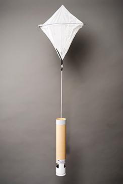
Intellectual Property Rights and Development
1)Standard deviation of differences between two successive repeated calibrations, k = 2 confidence level
Commercial GPS receiver Data Rates
Tuning range 400.16 ... 405.99 MHz Frequency stability < ±10 kHz RF power output < 200 mW Channel spacing 200 kHz Modulation FSK Harmonic and spurious outputAccording to EN302054 Telemetry range with recommended receiving antenna 325 km Battery Type Two lithium 123 cells in series Voltage 6 V nominal Life 2 hours (operating), 3 years (shelf) Pressure Sensor (P) Type Silicon capacitor Range From surface pressure to 3 hPa Resolution 0.01 hPa Repeatability 1) 0.4 hPa
Transmitter - EN302054
1)Standard deviation of differences between two successive repeated calibrations, k = 2 confidence level
1)Standard deviation of differences between two successive repeated calibrations, k = 2 confidence level
PTU update rate 2 Hz Wind update rate 4 Hz Descent Descent speed Approx. 11 m/s at sea level
Vaisala Inc., USA, manufactures and markets the Dropsonde RD41 and AVAPSâ Dropsonde Receiving System under license to University Corporation for Atmospheric Research Foundation (UCARF). The dropsonde and receiving system hardware and software have been developed at the Earth Observing Laboratory (EOL) of the National Center of Atmospheric Research (NCAR), in Boulder, Colorado, USA. AVAPSâ is a registered trademark of the University Corporation for Atmospheric Research. www.vaisala.com 83
Temperature Sensor (T) Type Platinum resistor Range –90 ... +60 °C Resolution 0.01 °C Repeatability 1) 0.1 °C Response time (when used and measured in Vaisala Radiosonde RS41): 6 m/s, 1000 hPa 0.5 s
Dropsonde RD41 Weight 350 g Size Diameter 70 mm, length 410 mm Maximum deployment airspeed325 KIAS (indicated airspeed) Shelf life 1 year from delivery
Wind (Horizontal)
Descent Time From 14 km Approx. 15 mins From 7.5 km Approx. 8 mins
Relative Humidity Sensors (U) Type Thin film capacitor Range 0 ... 100 %RH Resolution 0.1 %RH Repeatability 1) 2 %RH Response time (when used and measured in Vaisala Radiosonde RS41): 6 m/s, 1000 hPa, +20 °C < 0.3 s 6 m/s, 1000 hPa, –40 °C < 10 s

RI41 is an essential tool for carrying out ground preparation of Vaisala Radiosonde RS41. RI41-B is similar to RI41 but is equipped with a barometer module to provide an alternative to the ground check of the radiosonde’s pressure measurement or surface pressure observation. Both RI41 and RI41-B are configured and operated with Vaisala sounding systems.
RI41 and RI41-B Ground Check Device Features
•Fullyautomaticallycompliant with ETSI EN 302 291-1 and ETSI EN 302 291-2
•RI41-B is equipped with precise barometer module
•Detects and powers up RS41
RS41 ground check with RI41 and RI41-B Vaisala sounding system detects and automatically powers up RS41 radiosonde when it is placed onto the ground check device. Radiosonde preparation includes sensor functionality checks and setting the options for in-flight operational parameters, like timer to power off the radiosonde at the desired time, pressure, or altitude. During the preparation, the operator can also set the transmitter frequency of the radiosonde or apply the station default frequency.
A ground check of RS41 temperature sensor includes several advanced electrical checks and a comparison against the temperature element of the humidity sensor. For RS41 temperature sensor only comparison is made, meaning no corrections to radiosonde measurement are applied. Due to the lack of environmental control, the acceptance limits for the comparison are set accordingly. Humidity checks
The unique design of the sensors in RS41 enables automatic reconditioning and physical zero humidity check of the humidity sensor during ground preparations. Prior to flight, reconditioning effectively removes chemical contaminants that could affect the humidity measurement. The physical zero humidity check is based on generating dry conditions by heating the humidity sensor. This results in dry reference corrections that are more reliable than those made using drying desiccants with limited drying capacity. Pressure checks and surface pressure For the pressure measurement ground check, Vaisala sounding software compares the pressure sensor reading of RS41 with that of the RI41-B’s highly accurate, built-in barometer module and adjusts the measurement accordingly. Alternatively, an external precision barometer can be used for the comparison and the pressure value can be manually entered in Vaisala sounding Thesoftware.pressure measurement from the RI41-B barometer module can also be used as a surface pressure value, when sounding station parameters are set accordingly. Wireless communicationshort-rangelink RI41/RI41-B uses a wireless short-range data link for communication between RS41 and the sounding system. The link uses RF technology and has a range of 4 cm (1.57 in). During ground preparations, only RI41/RI41-B device is active, and there is no short-range transmitter on the radiosonde. The communication link operates at 13.56 MHz and is fully compliant with the ETSI EN 302 291-1 and ETSI EN 302 291-2 standards. 84
•Interface for wireless short range communication between Vaisala Radiosonde RS41 family and Vaisala sounding software
Temperature checks
Vaisala Ground Check Device RI41 – reliability with RS41 radiosonde.
•Interface is active – no short range transmitter in radiosonde
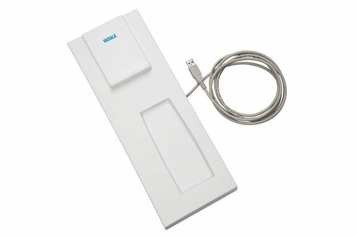
Calibration of the module Class A, NIST traceable Uncertainty 1) 0.15 hPa Long term stability 0.1 hPa/year
1)The recommended in-field calibration interval for barometer module is one year www.vaisala.com 85
Reference sensors
Electrical interface USB 1.1/2.0
Dimensions (H × W × L) 63 × 125 × 327 mm (2.48 × 4.92 × 12.87 in) Weight 1.1 kg (2.43 lb) Material Polyurethane Cable length 1.8 m (5 ft 11 in)
Transmitting power Max. 200 mW Communication link range 0.04 m (1.57 in)
Pressure Only in the RI41-B model
Cable with connector USB Inputs and outputs Power supply Input Via USB interface Voltage 5 VDC Typical current 300 mA Mechanical specifications
Operating humidity 10 ... 90 %RH Storage humidity 5 … 95 %RH Operating frequency (carrier) 13.56 MHz Short range wireless communicationRF technique
Technical data Operating environment Operating temperature +10 … +45 °C (+50 … +113 °F) Storage temperature -40 … +65 °C (-40 … +149 °F)
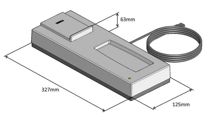
•Rugged radiosonde interface for Vaisala Sounding Systems MW32 and MW41
•Radiosonde can be prepared inside its protective cardboard package and with gloves or arctic mittens on
•Military grade switch activates the interface when radiosonde is placed onto MWH322 – no short range transmitter in radiosonde
• Utilizes wireless short range data link to communicate with Vaisala Radiosonde RS41
•Detects automatically the RS41 radiosonde and powers it up
Vaisala Radiosonde Ground Check Device MWH322 has been designed for the ground preparation of Vaisala Radiosonde RS41 in field conditions.
•Fully compliant with ETSI EN 302 291-1 and •Equipped-2with precise barometer modules
Versatile and Convenient MWH322 can be conveniently operated with both Vaisala MARWINâ Sounding System MW32 and Vaisala DigiCORAâ Sounding System MW41. MWH322 version for MW32 is equipped with a serial cable and it connects to MW32's serial radiosonde connector. The version for MW41 is equipped with a USB cable and it connects to a USB connector of the sounding PC.
The Vaisala Radiosonde RS41 sensors are all calibrated against references that are traceable to international standards (SI Duringunits).the radiosonde preparation procedure several steps are carried out including functionality checks for sensors and setting the radiosonde frequency and the optional in-flight operational parameters, like radio silence (with Vaisala Radiosonde RS41-SGM), and timer for turning the radiosonde power off either after desired time or altitude. For the ground check of the RS41 temperature sensor, several intelligent electrical checks and a comparison against the temperature element of the humidity sensor is conducted. For the RS41 temperature sensor only comparisons are made, thus no corrections to radiosonde measurement are applied. 86
MWH322 Ground Check Device Features
MWH322 can be operated on a desk, or attached to MW32’s handle. In case of a vehicle or shipboard installation, optional Vehicle Installation Kit can be used to mount it e.g. on a table or a wall. The kit has been tested to meet Crash Hazard Shock specification according to MIL-STD 810G, and it also allows quick removal of MWH322 if needed. As RS41 radiosonde is placed onto the MWH322 the sounding system MW32/MW41 detects the radiosonde and automatically powers it up. The radiosonde can be secured in place with a rubber strap. The version with serial cable has been tested to fulfill all relevant environmental specifications according to MIL-STD 810G, and electromagnetic emission and immunity specifications according to MIL-STD 461F. Ease of Use Thanks to the wireless connection, the radiosonde can be prepared inside its cardboard package, which protects sensors until balloon launch site. MWH322 can easily be operated with gloves or arctic mittens on. RS41 Ground Check at MWH322 The Vaisala Radiosonde RS41 temperature sensor is very stable utilizing linear resistive platinum technology. The humidity sensor integrates humidity and temperature sensing elements providing consistent results in all sounding conditions.
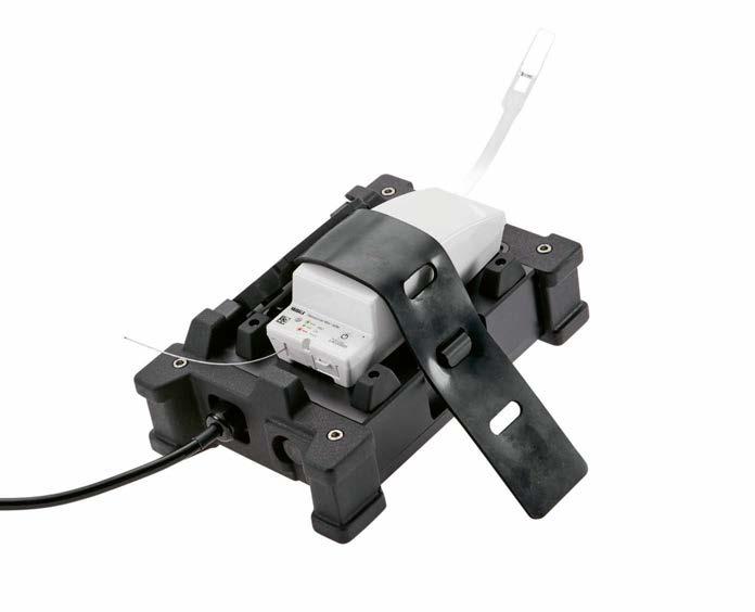
The unique sensor designs of Vaisala Radiosonde RS41 enable automatic reconditioning and physical zero humidity check of the humidity sensor during the ground preparations. Prior to flight, reconditioning effectively removes chemical contaminants that could affect humidity measurement. The physical zero humidity check is based on generating dry conditions by heating the humidity sensor. This enables long radiosonde storage time. This results in dry reference corrections that are more reliable than those made utilizing drying desiccants with limited drying capacity. The pressure measured with the precise barometer modules inside MWH322 can be used as a surface pressure in MW32 and MW41 sounding systems. The Short CommunicationRangeLink of MWH322 MWH322 utilizes wireless short range data link to communicate with Vaisala Radiosonde RS41. The communication link is based on the RF technology
Reliable Measurements
having a range of 4 cm. During ground preparations only the MWH322 device is active, while there is no short range transmitter on the radiosonde. The communication link is completely switched off when there is no radiosonde. A military grade switch activates the interface when radiosonde is placed onto MWH322. The short range communication link of Vaisala Ground Check Device MWH322 operates at 13.56 MHz and is tested to be fully compliant with the standard ETSI EN 302 291-1 and -2. 87
Technical data Operating environment Operating temperature −20 ... +50 °C Storage temperature −40 ... +71 °C Operating humidity 0 ... 100 %RH Storage humidity 5 ... +95 %RH Inputs and outputs Input From MW32 or PC Voltage, MW32 9 VDC Typical current, MW32 150 mA Voltage, PC 5 VDC Typical current, PC 200 mA Mechanical specifications Short range wireless communicationRF technique Frequency (carrier) 13.56 MHz Transmitting power Max. 200 mW Communication link range 0.04 m Electrical interface orMW32USB 1.1/2.0 Cable with connector MIL-C 26482 (MW32) or USB Cable length 1 m (MW32) or 1.5 m (USB) Weight 1.43 kg without handle locking 1.79mechanismkgwith handle locking mechanism Dimensions (H × W × L) 72 × 150 × 223 mm without handle locking mechanism 72 × 220 × 223 mm with handle locking mechanism Compliance IP rating IP65 Environmental tests MIL-STD-810G, see separate list Electromagnetic compliance MIL-STD-461F, see separate list Vaisala MARWIN Sounding System MW32 and Vaisala Ground Check Device MWH322 with Vaisala Radiosonde RS41-SGM in its cardboard package www.vaisala.com 88
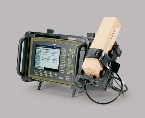
Features •Software Defined Radio technology for outstanding telemetry link performance and bandwidth e ciency • Optimum performance when used with the Vaisala RS41-SG, RS41-SGP, or RS41-SGM radiosonde.
Software Defined Radio Technology in Use SPS311G makes extensive use of Software Defined Radio (SDR) technology for receiving radiosonde signals. SDR technology is mature and commonly used today in a wide range of products including cellular base stations, military communication systems and public safety radios.
Radio ProgrammedTechnologyinSoftware
In SPS311G, most of the radio technology is programmed in software to work with a powerful Digital Signal Processor (DSP). This greatly improves flexibility and the future upgradability of both the hardware and software. SPS311G’s SDR receiver works with the Vaisala RS41 radiosonde family. When used with the Vaisala RS41 Radiosondes, SPS311G offers excellent telemetry link performance and bandwidth e ciency. As a sounding progresses, SPS311G receives the radiosonde and GPS signals by means of the SDR receiver and local antennas. SPS311G decodes the data and relays it to the sounding workstation for processing and archiving. 89
SPS311G Sounding Processing Subsystem
Vaisala Sounding Processing Subsystem SPS311G is the latest generation of the SPSseries for the Vaisala DigiCORAâ Sounding System MW41.
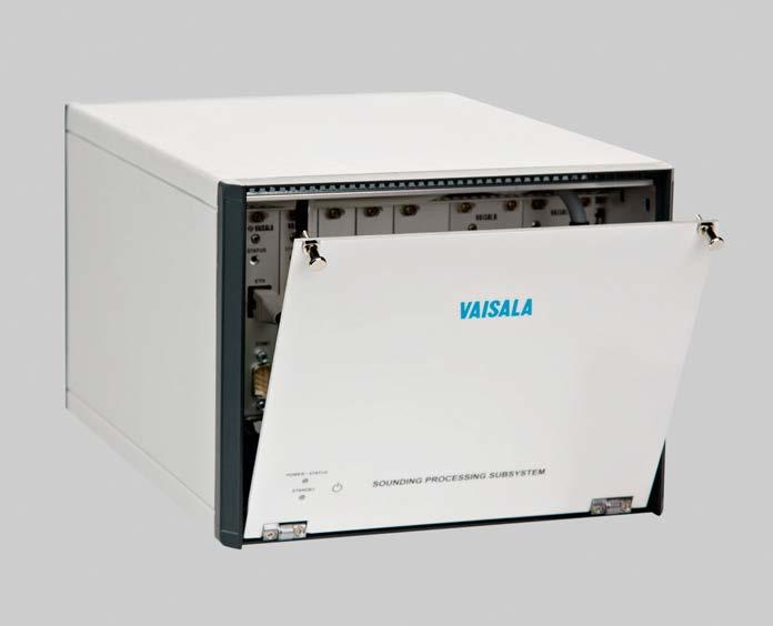
Operating environment Indoor use. Altitude up to 2000 meters. Operating temperature range 0 ... + 45 °C Operating humidity 10 … 90 %RH (non-condensing) Storage temperature -55 ... + 70 °C Storage humidity 5 … 95 %RH Mechanical specifications Dimensions 235 × 335 × 184 mm Weight 7.5 kg max.
Cooling system Forced air convection, three fans
Radio receiver system Modulation GFSK, GMSK, FM, FSK Frequency range 400.15 ... 406 MHz Sensitivity with RS41 and RS92 radiosondes -120 dBm Noise figure < 2.5 dB Image rejection 70 dB Spurious Free Dynamic Range with RS41 and RS92 radiosondes 90 dB Third Order Intercept Point (IIP3)0 dBm Input impedance 50 Ω (specifications valid with Vaisala telemetry antennas) www.vaisala.com 90
Technical data
UHF Connector Coaxial N-type female GPS Connector Coaxial TNC-type female VLF Connector Coaxial C-type female Antenna power Antenna amplifiers are powered through antenna cables
Inputs and outputs Power consumption 70 W max. Mains voltage nominal 100 ... 240 VAC Mains frequency 50 / 60 Hz DC power connection 19 … 36 VDC, 60 W max.
Portable Antenna Set Features set up with telemetry range - 150 km (93.2 mi) using RS41
•Easy
Vaisala Portable Antenna Set CG31 is a portable antenna designed to be used with GPS wind-finding systems. The antenna set consists of a Helix UHF antenna with antenna amplifier and GPS antenna on a tripod. The antenna set is painted green as standard. One person can handle and assemble the antenna set. CG31 receives radiosonde signals in 400 MHz meteorological UHF band.
CG31
series GPS radiosondes
captive parts •Long
the
91
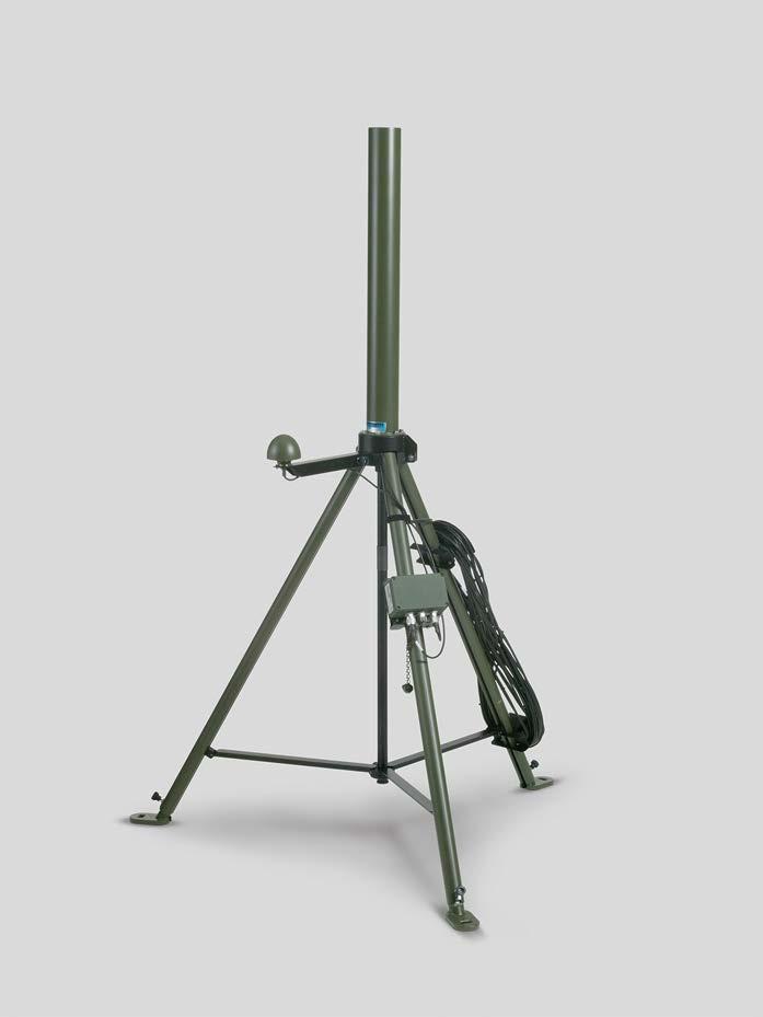
Diameter Footprint 1133 mm (44.61 in) Total height assembled 1695 mm (66.73 in)
GPS antenna Primary power +5 VDC (±10 %) Power consumption 22 mA, 0.11 W (nominal) Output impedance 50 Ω Frequency L1 (1575 MHz)
Transportation case dimensions1380 × 355 × 385 mm (54.33 × 13.98 × 15.16 mm)
Operating temperature range −40 ... +55 °C (-40 ... +131 °F)
Technical data
Storage temperature −50 ... +71 °C (-58 ... +159.8 °F) Storage humidity 0 ... 100 %RH
Azimuth coverage 360° (omni-directional)
Operating environment
Connector UHF Antenna Coaxial N-type female GPS Antenna Coaxial TNC-type female Weight With cables 10.5 kg (23.15 lb) With accessories and transport case23 kg (50.71 lb)
Mechanical specifications
www.vaisala.com 92
Polarization Right-Hand Circular Polarization (RHCP) VSWR 2 : 1 Axial ratio 2 dB at zenith, 10 dB above 10° elevation Gain 35 dB (nominal) Noise 2.75 dB (nominal) Pass-band width 50 MHz
Elevation coverage 0° to 90° elevation (hemispherical)
Standard cable length 20 m (65 ft)
Operating humidity range 0 ... 100 %RH Operating precipitation Unlimited Maximum wind speed 65 m/s (145 mph)
Vaisala Vehicle Antenna Set CG32 is an antenna configuration designed to be used for operation in vehicles. The antenna set can be used with GPS wind finding systems out in the field. 93
CG32 Vehicle Antenna Set
Vaisala Vehicle Antenna Set CG32 receives radiosonde signals in 400 MHz meteorological band. The antenna set can be used in conjunction with the Vaisala MARWINâ Sounding System MW32. Easy to Assemble CG32 can be mounted on a vehicle-wall or mast. The antenna set is delivered with Antenna Amplifier and Switch RAA111 and the antenna cables connected.
Designed for Field Operation Conditions
The antenna set consists of a UHF antenna, a spring base with a GPS antenna, and Antenna Amplifier and Switch RAA111 at the base of the antenna. The antenna can be attached to a vehicle wall with a mounting plate, or it can be mounted on a mast. The color of the antenna parts is adjusted for field operation conditions and the metal parts are made from stainless steel, brass and aluminum. One person can transport and assemble the antenna set.
Features •Fixed to the vehicle - no need to erect and dismantle a tripod • Rugged and durable • Long telemetry range - 150 km (93.2 mi) using the RS41 series GPS radiosondes
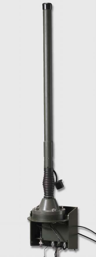
Technical data UHF Antenna Type Centered dipole Frequency range 400 ... 406 MHz Gain 2 dBi Polarization Vertical Horizontal pattern Omni-directional Telemetry range With RS41 series GPS radiosondes150 km (93.2 mi) Amplifier Gain 20 dB typical Noise figure < 2 dB Power input +10 ... 12 typicallyVDC,130mA through RF cable Output impedance 50 Ω, VSWR < 1.5 CG32 internal and external cables UHF antenna radiation pattern - elevation www.vaisala.com 94
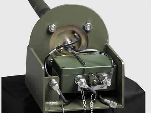
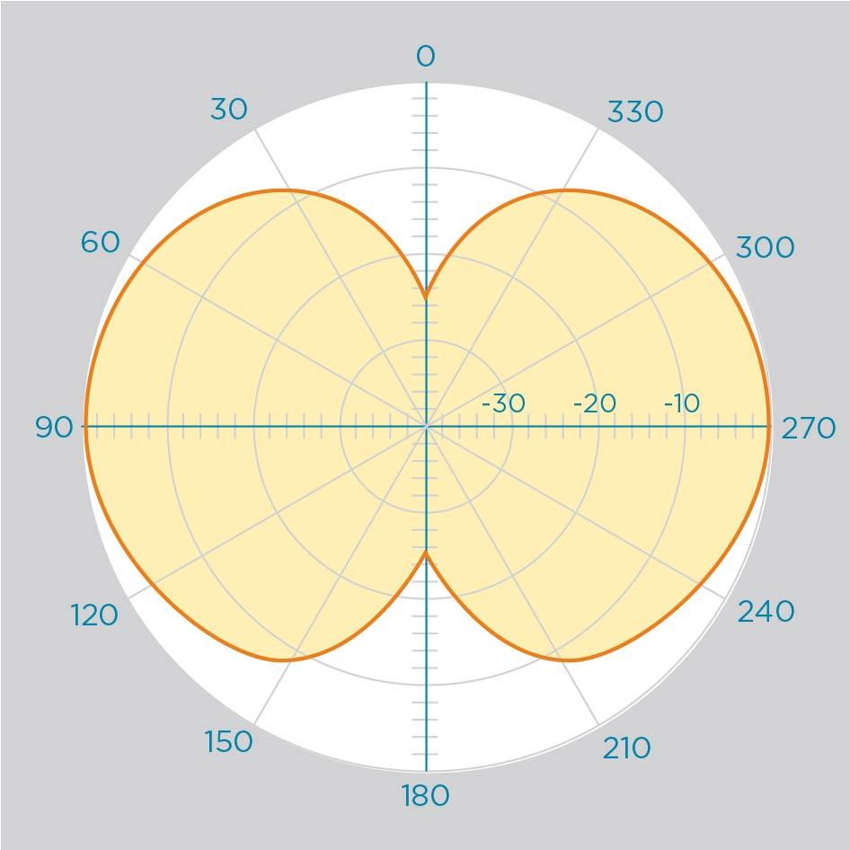
FB13
Vaisala Filling Balance FB13 is used as ballast when filling radiosonde balloons in order to obtain the correct lift (free lift + payload) for the sounding balloon.
During balloon filling, the required nozzle lift is obtained by loading the nozzle with additional weight. The FB13 nozzles are made of aluminum, and are grounded to remove possible static electricity formed during the balloon inflation. The weights are made of stainless steel. Nozzle lifts from 0.4 kg to 2.8 kg for the big nozzle, and from 0.3 kg to 2.7 kg for the small nozzle can be obtained by loading weights in intervals of 0.1, 0.2, and 0.4 kg onto the nozzle. www.vaisala.com 95
•Two nozzles for balloons with different sized necks •Grounded to remove static electricity
Grounding Removes Static Electricity
Vaisala Filling Balance FB13 facilitates the use of radiosondes. It is used as ballast for obtaining the correct nozzle lift (free lift plus payload) for the sounding balloon. Nozzle lift refers to the weight a balloon is capable of lifting when filled. In addition, the balance also acts as a gas inflation pipe.
Ballast for Optimizing Nozzle Lift
Filling Balance Features
Two Nozzle Sizes for Convenient Filling FB13 contains two different nozzles for convenient attachment of balloons with small and large neck diameters. The balloon neck is secured on the nozzle with a spring clamp. Each nozzle has a clamp of its own, and the nozzles are easily interchangeable. The small nozzle is 130 mm high with a diameter of 20 mm. The large nozzle is 150 mm high with a diameter of 42 mm.
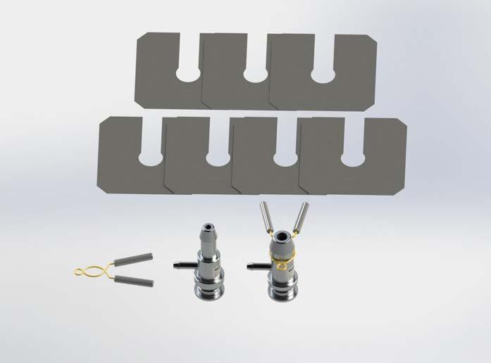
Vaisala GPS Antenna GA31 is used with the Vaisala Sounding Systems for the local reception of GPS signals when performing GPS soundings. GA31 is suitable for stations equipped with the GPS wind finding system. 96
•Epoxy seal for protection against ambient conditions
GA31 GPS Antenna
•33 meter long N-to-TNC cable for connecting to sounding instruments.
Vaisala GPS Antenna GA31 allows Vaisala Sounding Systems to gather orbital and other navigational data directly from the GPS satellites. The local reception is also used to get differential corrections for positioning.
•35 dB pre-amplifier
Achieving Optimal Reception GPS signal reception requires an unobscured line-of-sight to the GPS satellites. Seen from the zenith, an open sky angle of at least 75 degrees is necessary. The best reception is achieved with a location that has a clear view of the sky down to the horizon in every direction. The Vaisala GPS Antenna GA31 is equipped with a 35 dB pre-amplifier. A band pass filter renders the GA31 immune e.g., to Inmarsat and radar interference. Protected against Weather Conditions The Vaisala GPS Antenna GA31 is sealed with epoxy for protection against ambient conditions. It is shipped with a 1.5-meter aluminum pole with a castaluminum flange and pole mounting clips and 33 meters of cable.
•Receives data from GPS satellites
Features
Data Directly from GPS Satellites
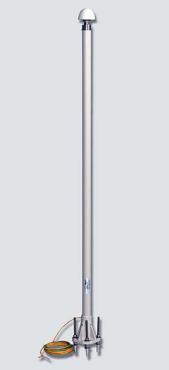
Technical data
General VSWR 2:1 Axial ratio 2 dB at zenith, 10 dB above 10° elevation Gain 35 dB (nominal) Noise figure 2.75 dB (nominal)
www.vaisala.com 97
Polarization Right-hand circular polarization (RHCP)
Pass-band width 50 MHz Cable attenuation 17 dB > A > 7 dB at 1.5 GHz Azimuth coverage 360° (omni-directional) Elevation coverage 0 … 90° (hemispherical)
Mechanical Specifications Weight (without cables) 2.6 kg Height 1.6 m Mounting Pedestal flange or pole clamps
Inputs and Outputs
Operating Environment Operating temperature -40 … +85 °C Storage temperature -55 … +100 °C Operating humidity 0 … 100 %RH Storage humidity 0 … 100 %RH Operating precipitation Unlimited Maximum wind speed 65 m/s
Primary power +5 VDC (±10 %) Power consumption 22 mA, 0.11 W (nominal) Output impedance 50 Ω Operating frequency L1 (1575 MHz)
RM32 Telemetry Antenna Features •Radiation pattern optimized for radiosonde reception • Long telemetry range, up to 200 km •For use with RS41 SG, RS41 SGP, or RS41 SGM radiosonde •Includes vertical and helix antennas
Optimal Performance in All Elevation Angles RM32 has 2 antenna elements which have been selected to optimize the performance in all elevation angles, both near the horizon and at the zenith. The vertical antenna has a maximum gain of 5 dBi just below zero elevation, and the helix antenna has approximately hemispheric coverage and a maximum gain of 3 dBiC at the zenith. Selects the Antenna with the Best Reception RM32 includes an antenna amplifier with a two-position antenna switch, through which the sounding system selects the antenna with the best reception. All the amplifier parts are housed in a waterproof box at the base of the antenna mast. The amplifier runs on DC voltage supplied by the UHF receiver.
For Fixed and Portable Systems RM32 is well suited for fixed installations, but it can also be used in portable systems, when feasible. The mounting sleeve at the bottom of the tubular stand makes it easy to install the whole antenna assembly on top of an external mast.
Vaisala Telemetry Antenna RM32 is an omnidirectional UHF antenna used with the Vaisala DigiCORAâ Sounding System to receive radiosonde signals in the 400 MHz meteorological band. It includes 2 antenna elements and a switch for selecting the antenna element with the best reception.
98
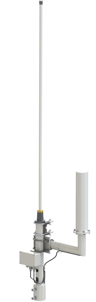
99
Technical data
Height with tubular mast 1912 mm Weight (with antenna cable) 11.4 kg Weight (without antenna cable)6.3 kg
Distance between the antennas300 mm Antenna cable Connector Coaxial N-type male Standard length 33 m Mounting sleeve for mounting to external mast Inner diameter 61.5 mm Depth 90 mm Operating Environment Operating temperature −40 … +55 °C Operating humidity 0 … 100 %RH Operating precipitation Unlimited Maximum wind speed 65 m/s Storage temperature −50 … +100 °C Storage humidity 0 … 100 %RH www.vaisala.com
Antennas Frequency range 400.15 … 406 MHz Vertical Antenna Directivity 5.1 dBi Polarization Vertical Horizontal pattern Omnidirectional Helix Antenna Gain 3 dBiC Polarization Right-hand circular Horizontal pattern Omnidirectional with hemispheric coverage Telemetry Range With RS41-SG, RS41-SGP, and RS41SGM radiosonde 200 km Amplifier Gain 20 dB typical Noise figure < 2 dB Operating voltage +10 … 12 VDC Typical power consumption 130 mA through antenna cable Output impedance 50 Ω VSWR < 1.5:1
Mechanical Specifications
The Vaisala Radiotheodolite RT20A is easy to assemble, dismantle and transport by truck, trailer or helicopter. The RT20A accurately locates radiosondes during soundings using a modern interferometric technique and light tracking motors. Advanced signal processing ensures data accuracy and reliability. The RT20A meets all the operational needs of defense forces while fulfilling stringent environmental and EMC/EMI requirements.
The Vaisala Radiotheodolite RT20A compensates for this by means of a tilt sensor that automatically adjusts the RT20A's mechanical attitude. This feature ensures that correct wind data is collected even in di cult terrain and sounding conditions.
Ready for Sounding in under 15 Minutes
Accurate Calculation of Azimuth and Elevation Angles
RT20A Radiotheodolite Features •Meteorological profile data for artillery ballistic preparation and numerical weather prediction •Independentmodels and passive windfinding
Accurate Wind Data Even at Low Elevation Angles
The angle at which the radiosonde signal arrives at the RT20A is calculated by means of phase comparison. This method uses mathematical formulas that are applicable regardless of signal strength or variations in radio frequency.
When disassembled in its rugged carrying cases, the Vaisala Radiotheodolite RT20A can be transported with light vehicles. After arriving onsite, it is quick to assemble.
The Vaisala Radiotheodolite RT20A is the independent and passive windfinding solution available as an option for Vaisala sounding systems.
The windfinding accuracy of the Vaisala Radiotheodolite RT20A is maintained even at low elevation angles, where ground reflections can cause some theodolites problems. The typical wind vector error (standard deviation) is less than 1 m/s at elevation angles above 17 degrees and less than 1.5 m/s above elevation angles of 15 degrees up to an altitude of 20 kilometres. Good accurary is achieved even at an elevation angle of 12 degrees. This accuracy is a result of the RT20A's excellent attenuation of ground reflection, its sophisticated data processing capabilities, and its unique antenna array design. Automatic Tilt Compensation for Dependable Data Soft ground or snow can cause the mechanical attitude of a radiotheodolite to shift during a sounding, leading to erroneous elevation angle and wind data.
Off-axis tracking ensures high accuracy without using conventional servomotors. Zero-backlash synchronized encoders measure the mechanical attitude of the RT20A with great accuracy. The mechanical and electronic measurements are combined, and the true azimuth and elevation angles are calculated accurately. This combination of electronic and mechanical measurement ensures reliable operation and uses small servomotors that consume little power. 100
The four interchangeable antenna elements have quick-lock mechanismstwo experienced operators will have the RT20A ready for sounding in under 15 minutes. Alternatively, the RT20A can be installed and operated on a trailer.
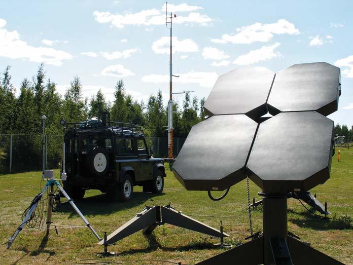
General Average wind vector accuracy (calculated from METCM messages) Better than 1 m/s with EL angle > 17° Distance from antenna to Sounding Processor Max. 30 + 30 m Primary power 115/230 VAC or 24 VDC (vehicle battery) Operating temperature -30 … +55 °C (Radiotheodolite) Antenna Tracking principle Phase comparison Antenna type Four 24-element arrays Polarization Vertical Gain Min. 16 dBi Side lobe attenuations > 20 dB to the direction of specular ground reflection on flat terrain when EL angle > 14° AZ-EL Platform
Rotation Continuous azimuth -5° to 95° elevation Drives DC motors with low backlash reducing gears Slewing speed 25°/s, AZ and EL. Angular position reading Synchro decoders, no backlash, 0.02 w° resolution (14 bits)
www.vaisala.com 101
Receiver Tuning frequency range 1660 ... 1700 MHz Tuning Manual with automatic frequency Automaticcontrol search and lock on Sensitivity -110 dBm RF input and 12 dB S+N/N IF bandwidth 300 kHz Automatic gain control dynamic range-110 dBm ... 0 dBm Dimensions Height 2300 mm Foot span diameter 2400 mm Antenna Arrays Height 1740 mm Width 1190 mm Weight 172 kg ~1190 ~1740 ~2300 R~1200
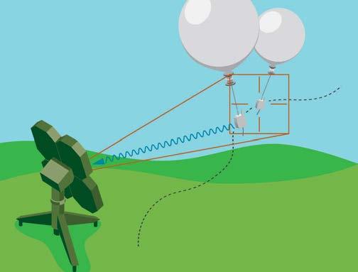
•Reliabletransfer data collection and transmission. 102
Robust Design for Extreme Conditions
•Vaisala DigiCORAâ Sounding System MW41 with a no-break power supply and the necessary software and hardware options.
ASAP Sounding Station Features
Accurate
User Friendly Operation
The Vaisala ASAP Station consists of:
The Vaisala ASAP Sounding Station includes the DigiCORAâ Sounding System that requires the minimum amount of time from the operator prior to balloon release. Sounding preparation phase can be easily followed with the sounding system user interface. The ASAP container offers comfortable and air-conditioned room for the operator during the sounding preparation phase, protecting at the same time from the current conditions at the sea. Balloon filling and release actions are performed by simply operating two separate control levers. After the balloon and radiosonde are released all actions are automatically fulfilled including message transmission.
MeasurementsMeteorological
•Optionally Vaisala Automatic Weather Station for making the surface PTU and wind observations.
Vaisala ASAP Sounding Station is a semi-automatic upper-air observation station for use on-board ships. ASAP receives the radiosonde signals and converts them into meteorological messages.
• Easy to install, operate and
•Upper-air observation station for marine •Radiosondeconditions.datacollection and transmission in standard WMO message format, TEMP SHIP and •RadiosondeBUFR. launcher: ALS211
•Vaisala RS41 radiosondes
The Vaisala ASAP Sounding Station converts radiosonde signals into meteorological messages, which are forwarded in standard WMO message format, TEMP SHIP and BUFR through satellite system to land station. Vaisala automatic weather stations can be integrated in order to bring data into the system for surface weather observation and SYNOP SHIP message.
The Vaisala ASAP Sounding Station uses Vaisala RS41 family radiosondes that measure air pressure, temperature, relative humidity and wind direction/ speed. Wind-finding methods are based on the GPS.
The Vaisala ASAP Station is housed in a 10-foot container. It meets the international requirements for mechanical construction (ISO), with a design that applies to the original specifications set by the ASAP Coordinating Committee (ACC) including certain carefully considered modifications. Vaisala Balloon Launcher ALS211 protects the meteorological balloon during the filling and launches the radiosonde. It has been designed for marine applications thus the functionality of the balloon launcher is reliable even in most extreme weather conditions at sea.
•Vaisala ALS211 semiautomatic radiosonde launcher which includes electrical heaters and air-conditioner. Benefits •Very compact structure
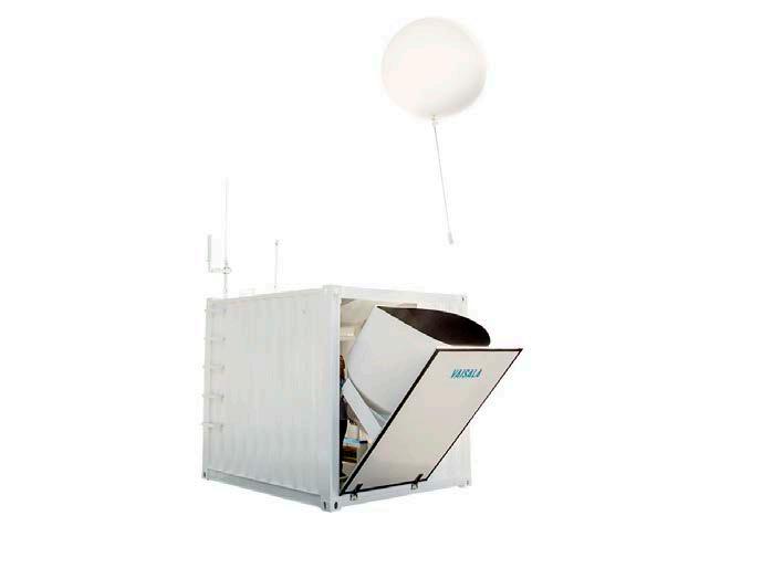
Windprofiling
Technical Data Vaisala DigiCORAâ Sounding System MW41
Gross weight without gas bottles 2400 kg
Operating
Interior is insulated with fireproof mineral wool and paneled with fibre cement flat Racksheetsforelectrical equipmentsAISI304 Electricity Power consumption 4.2 kW without transformer option 6 kVA (1-phase with transformer 6option)kVA(3-phase with transformer option)
Optional input voltages (with transformer option): 220/380/400/440 VAC, 3-phase or 1phase Supply frequency 50/60 Hz for 60 Hz supply; air conditioner should be selected correspondingly Lights 2 x 9 W ceiling lights Heating 2 x 750 W radiators
Sounding Workstation Ruggedized laptop delivered by Vaisala, including pre-installed DigiCORA Sounding Software, system recovery tools including USB drive with recovery image, and optional Edgeport serial extension. system Windows, pre-installed Ground check UninterruptibledevicePower Supply (UPS) Vaisala Sounding Processing Subsystem SPS311 options Code correlating GPS Antenna Antenna options Directional UHF GPSOmnidirectionalantennaUHFantennaantenna Antenna stand Acid proof (AISI316), fitting for container roof installation Surface Weather System ASAP Launcher ALS211 Mechanical Specifications Dimensions 2991 x 2438 x 2591 mm (l x w x h)
Air conditioner Launcher Vessel Material Fiberglass Balloon size 350 - 500 g Control Controlled by pneumatic actuators
Launch door Stainless steel Options Compressor and pressurized air tank Main transformer with volt meter3-phase 6 kVA or 1-phase 6 kVA Storage cabinet 1030 x 500 x 2000 mm OR gas bottle rack 8 gas bottles
Filling gas regulator Ladder steps 6 pcs www.vaisala.com 103
Options Vaisala Automatic
Nominal input voltages 230/400 VAC, 3-phase; or 230 VAC 1phase
Observing

16817 Balloon Nozzle Features •Enables automated filling and releasing of the balloon •Connects the balloon to the radiosonde tray • Connects the unwinder to the balloon
The nozzle body is made of conductive plastic and it is attached to the balloon neck. The balloon neck is fitted tightly around the nozzle body by using a plastic ring. Vaisala Radiosonde RS41 unwinder is then connected to the nozzle body. 104
Vaisala Balloon Nozzle 16817 is a special gas-tight valve that is inserted inside each balloon during balloon preparation. It connects the balloon to the radiosonde tray and allows safe automated filling and release of the balloon. The flow path of the balloon nozzle opens during balloon filling, and is automatically closed after filling by an internal spring. Compatible with Vaisala AUTOSONDEs
The nozzle is designed to be used with Vaisala AUTOSONDEâ AS15 and Vaisala AUTOSONDEâ AS41. Connecting balloon, nozzle, and unwinder
Vaisala Balloon Nozzle 16817 is used in Vaisala Automatic Sounding Stations to enable automated filling and release of the balloon. Enables automatic filling and release
Technical data Mechanical specifications Dimensions (H × Ø) 50 × 35 mm Weight 16 g Parts Nozzle body Plastic ring for folding the balloon neck 50 Ø35 Nozzle dimensions in millimeters www.vaisala.com 105
Present weather identification 1) 2)
FD70 Forward Scatter Sensor Features •Visibility up to 100 km (62 mi) •Precipitation type identification, intensity, and accumulation •Droplet size distribution and •Exceptionalreflectivity precipitation detection sensitivity •Superior •Look-downdifferentiationliquid/frozengeometry to minimize measurement disturbances •Enhanced visibility measurement in sand dust conditions
Calibration traceability To ensure specific visibility and rain performance, Vaisala continuously compares calibrated FD70 units against reference sensors in the Vaisala outdoor test field. Every delivered unit can be traced back to this set of calibrated reference sensors. 106
Novel use of a single thin light sheet instead of the conventional light cone results in high detection sensitivity, enabling scatter-property analysis of each single particle and allowing detection of even the smallest drizzle droplets. Particle size and fall speed distributions provide additional information, enhancing precipitation type identification. The receiver measures forward scattered light at an angle of 42° with a very high sampling rate and powerful signal processing. Measurement arrangement and method is patented. Visibility measurement FD70 forward scatter technology provides the most representative extinction coe cient (EXCO) determination possible. Scatter-property analysis reliably calculates the visibilityreducing effect of precipitation, allowing meteorological optical range (MOR) reporting in the most challenging conditions. FD70 covers all application needs, including measurement performance and capability requirements for runway visual range (RVR).
Reliable in all weather FD70 has multiple features to ensure reliable operation even in extreme weather conditions. Effective hood heating and proven look-down geometry protect the sensor windows against external disturbances. These are complemented with independent optical path monitoring and window contamination
1)Optional
Precipitation measurement Due to its innovative technology, FD70 reliably detects and identifies precipitation types that have been challenging for conventional technologies.
Vaisala Forward Scatter Sensor FD70 combines forward scatter and optical disdrometer technologies. FD70 sets the standard in precipitation identification and quantification, providing best-in-class visibility determination.
Innovative technology
•Rain•Drizzle•Snow•Snowgrains•Icecrystals•Icepellets•Freezingdrizzle•Freezingrain•Snowpellets•Hail•Fog•Freezingfog•Mist•Haze•Dust
2)In addition to listed types, reports a variety of mixed precipitation types
NWSWMOFD70criticalofenableSelf-diagnosticscompensation.andmodulardesignshortservicetimes.Redundancydatacommunicationisavailableforcasessuchasairportuse.complieswithICAO,FAA,andrequirementsandusesWMOandweathercodesinreporting.
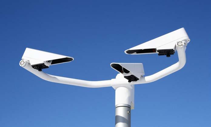
Reporting resolution and uncertainty 1) 0.01 mm (0.0004 in), ±2.2 % Reporting range, snow height0 … 9999 mm (0 … 32 ft 9 in) Reporting resolution, snow height1 mm (0.04 in) Additional precipitation reporting
Radar reflectivity −9.9 … 99.9 dBZ Kinetic energy 0.000 … 999.999 J/m2 × h 1)Proven under laboratory conditions.
Compliance EU directives and regulations EMC, LVD, RoHS
External inputs Vaisala HUMICAPâ Humidity and Temperature Probe HMP155
Precipitation accumulation Reporting range 0 … 999.99 mm (0 … 40 in) liquid water accumulation (LWA)
EMC compliance EN 61326 1, industrial environment CISPR 32 / EN 55032, Class B www.vaisala.com 107
Vaisala Background Luminance Sensor LM21
Coating Multi-layer coating to prevent environmental corrosion Dimensions, measurement unit354 × 551 × 883 mm (13.94 × 21.69 × 34.76 in) Weight, measurement unit Max. 7.5 kg (16.5 lb)
Measurement specifications
Operating voltage Measurement unit with interface unit: 115/230 V AC ±10 %, 50 … 60 Hz Measurement unit only: 10 … 50 V DC
Sampling frequency 5 MHz Measurement cycle 5 s Mechanical specifications
Dimensions, interface unit with radiation shield 885 × 380 × 320 mm (34.84 × 14.96 × 12.60 in) Weight, interface unit with electronicsMax. 25 kg (55.1 lb)
Operating temperature, extended (optional) −55 … +65 °C (−67 ... +149 °F)
Compatibility System compatibility Vaisala AviMetâ Backwards compatibility Vaisala FD12(P), FS11(P), PWD Series
Reporting range 1 m … 100 km (3 ft … 62 mi) Reporting resolution 1 m (3 ft) Reporting uncertainty in operational conditions ±10 % or ±1 m at 1 m … 10 km (±3 ft at 3 ft … 6.2 mi) 1) ±20 % at 10 … 100 km (6.2 … 62 mi)
Weather codes SYNOP: WMO table 4680 METAR: WMO table 4678 NWS Light,codesmoderate, and heavy intensities
Size / speed measuring rangeØ 0.1 … 35 mm (0.004 … 1.38 in) 0 … 10+ m/s (0 … 32.8+ ft/s)
Present weather identification Drizzle, rain, snow, snow grains, ice crystals, ice pellets, freezing rain / drizzle, snow pellets, hail, fog / freezing fog, mist, haze
Material, measurement unit Aluminum Material, interface unit Maritime-grade aluminum (EN AW-5754)
Inputs and outputs
Heating voltage 24 V AC or V DC ±10 % Power consumption, typical Measurement unit with interface unit, all options: 245 W Measurement unit: 10.0 W / 24 V Measurement unit, heating: 180 W (at 60 W per hood)
Storage temperature −55 … +65 °C (−67 ... +149 °F), non condensing environment Operating humidity 0 … 100 %RH Wind speed Up to 60 m/s (134 mph)
Backup battery (optional) 12 V 2.6 Ah
Precipitation Intensity Sensitivity Single droplet Ø ≧ 0.1 mm (0.004 in) Reporting range 0.01 … 999.99 mm/h (0.0004 … 40 in/h) liquid water equivalent (LWE)
Technical data Visibility (MOR) measurement
Droplet size / fall speed distribution41 size classes, 26 speed classes
Measurement error ±0.7 %
Operating environment IP rating IP66 Operating temperature −40 … +65 °C (−40 … +149 °F)
1) Fulfills ICAO Annex 3: ±50 m (164 ft) up to 600 m (1968 ft). Present weather reporting (optional)
Operating principle Look-down forward scatter Scattering angle (main receiver)42° ±0.25° Scattering angle (side receiver)90° ±0.25° Light source Near-infrared
Environmental IEC 60068 2 1, 2, 6, 14, 30, 31, 52, 78 IEC 60529, VDA 621 415 IEC/EN 63000 Eye safety Class 1M IEC / EN 60825 1:2014 Electrical safety IEC/EN/UL/CSA 61010 1
Precipitation measurement (optional)
Reporting resolution 0.01 mm/h (0.0004 in/h) Minimum intensity 0.01 mm/h (0.0004 in/h)
Data communication options 10/100 Mbps Ethernet RS-232, Leased-lineRS-485modem DXL421 UHF/VHF radio modem
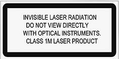
Scientifically valid chain of calibration FS11 is calibrated through a scientifically valid chain of reference. The scattering response of the calibration device can be clearly traced to a reference FS11 visibility sensor, which is in continuous operation at Vaisala outdoor test field along with reference transmissometers and other instrumentation. The visibility measurement of FS11 is also traceable to FAA reference sensors.
Visibility Sensor FS11 is intended for the most demanding weather applications, such as runway visual range (RVR), aeronautical and synoptical visibility. It provides the optimal combination of the best accuracy, the highest reliability, broad measurement range, and low maintenance need.
FS11 Visibility Sensor Features •Unique window contamination •Accurcorrectionateand traceable forward scattering measurement •Technical design and high-power heating according to FAA •Frangibleguidelinescomposite fiber mast •Can be upgraded for sensing present weather Benefits •The most widely proven forward scatter RVR sensor • Visibility sensor selected and used by •MeetsFAAFAA and ICAO harbors.visibilitydemandingFS11aeronauticalvisualThe•Meets•Minimal•Can•AccuratespecificationsandtraceablemeasurementbeusedforbothaeronauticalandsynopticalapplicationsmaintenanceneedsICAOfrangibilitystandardsmainapplicationsofFS11arerunwayrange(RVR)andsynopticalandvisibilitymeasurements.isalsowellsuitedforotherapplications,suchasmeasurementatportsand
Low maintenance need FS11 incorporates a technique that measures and compensates for window contamination. It ensures unparalleled measurement accuracy between window cleanings. It also enables much longer window cleaning intervals than compared to conventional visibility Thesensors.unique system works by monitoring the total reflectance of the window surface. It automatically compensates for visibility measurement errors caused by window contamination. The sophisticated self-diagnostics and modular design allow for very short service times. The measurement fork and optional background luminance sensor LM21 are independent instruments that can be replaced quickly as pre-calibrated spare parts.
Four main design features are combined in FS11 to ensure reliable operation in the harshest weather. The first is the window compensationcontaminationtechnique.The second is the “head-down” design of the optical heads, which protects them against virtually all windblown particles (even those flying horizontally). High-power heaters are the third feature. Each heater has its own temperature monitoring and control mechanism to prevent snow accumulation during the heaviest snowstorm. As a final measure, there is an optical path clearance monitoring circuitry to verify that measurement is not affected by obstructions.
Reliable operation in the harshest weather
108
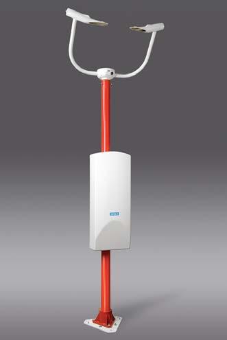
Mechanical specifications Dimensions
Outputs Serial data line RS-232 or optoisolated RS-485 (2-wire) or optional data Separatemodemmaintenance line RS-232 +12 VDC max. 800 mA output for option powering Overvoltage category CATII Output data Automatic or polled visibility and sensor status data message with selectable message interval
0.9 × 1.0 m (9.19 × 2.95 × 3.28 ft) Weight without mast 37 kg (81.57 lb) Weight, including Frangible Mast FSFM250 52 kg (115 lb) Mast Frangible and hinged glass fiber mast Optical specifications Operating principle Forward scatter measurement Scattering angle 42° Light source Near-infrared LED Compliance EMC compliance Electrical safety IEC/EN 61010 1 EMC immunity EN 61326 1, industrial environment EMC emissions EN 55032:2012, Class B EN 61000-3-2 EN 61000-3-2 Directives EU directives and regulations RoHS Directive (2011/65/EU) amended by 2015/863 EMC Directive (2014/30/EU) Low Voltage Directive (2014/35/EU) Compliance marks CE, RCM, UKCA Spare parts and accessories Calibration set FSA11 Background luminance sensorLM21 Battery backup FSB101 Modem for long distance communication (> 1 km / 0.6 mi) DMX501 Obstruction light FS11OBS Transformer FS45002SP Calibration set PWA12 Maintenance cable QMZ101 www.vaisala.com 109
Technical data Measurement performance
Operating environment Operating temperature −40 ... +65 °C (−40 ... +149 °F) −55 ... +65 °C (−67 ... +149 °F) (optional) Operating humidity 0 … 100 %RH Wind speed Up to 60 m/s (134 mph) operating altitude 3000 m (approx. 9800 ft) Pollution degree 2 IP rating IP66 (H × W × D) 2.8 ×
Measurement range of MOR 5 ... 75 000 m (16 ft ... 46.6 mi) with 1, 3, and 10 min averaging Reporting uncertainty ±10 % range 5 ... 10 000 m (16 ft … 6.2 mi) ±20 % range 10 000 ... 75 000 m (6.2 … 46.6 mi)
Battery backup option Battery 2 Ah, typical backup time 30 min at 25 °C (77 °F) and 5 min at −40 °C (−40 °F)
Scatter measurement accuracy±3 % Inputs and outputs AC (mains) power supply 100/115/230 VAC ±10 %, 50 ... 60 Hz Power consumption Max. 300 VA (60 VA + 240 VA defrosting heaters)
Maximum
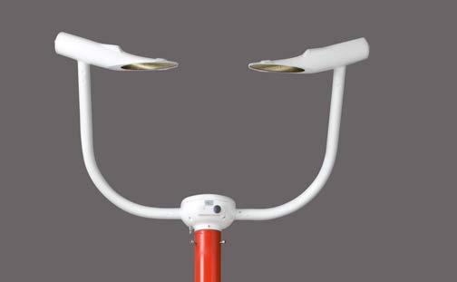
Thesensors.unique system works by monitoring the total reflectance of the window surface. It automatically compensates for visibility measurement errors caused by window contamination.
Four main design features are combined in FS11P to ensure reliable operation in the harshest weather. The first is the window compensationcontaminationtechnique.The second is the “head-down” design of the optical heads, which protects them against virtually all windblown particles (even those flying horizontally).
Scientifically valid chain of calibration FS11P is calibrated through a scientifically valid chain of reference. The scattering response of the calibration device can be clearly traced to a reference FS11P visibility sensor, which is in continuous operation at Vaisala outdoor test field along with reference transmissometers and other instrumentation. The visibility measurement of FS11P is also traceable to FAA reference sensors.
FS11P Present Weather Sensor Features •Unique window contamination •Usescorrectionthesame principles as the renowned FD12P weather sensor • Accurate and traceable forward scattering measurement •Technical design and high-power heating according to FAA •Frangibleguidelinescomposite fiber mast Benefits •Excellent value: RVR, visibility, and present weather all-in-one • The most widely proven forward scatter RVR sensor •Visibility sensor selected and used by •MeetsFAAFAA and ICAO •Canspecificationsbeusedfor both aeronautical and synoptical applications •Minimal maintenance needs •Compatible with FD12P •Meets ICAO frangibility standards
Vaisala Present Weather Sensor FS11P is intended for the most demanding weather applications such as runway visual range (RVR), aeronautical and synoptical visibility, and present weather observation. It provides the optimal combination of the best accuracy, the highest reliability, broad measurement range, and low maintenance need.
110
High-power heaters are the third feature. Each heater has its own temperature monitoring and control mechanism to prevent snow accumulation during the heaviest snowstorm. As a final measure, there is an optical path clearance monitoring circuitry to verify that measurement is not affected by obstructions. Technical compatibility In addition to the technological similarity, FS11P is compatible with and can be used to replace FD12P. They both provide the same mechanical, electrical and communication interfaces, and they transmit similar message formats widely used in aviation and meteorology.
Low maintenance need FS11P incorporates a technique that measures and compensates for window contamination. It ensures unparalleled measurement accuracy between window cleanings. It also enables much longer window cleaning intervals than compared to conventional visibility
The sophisticated self-diagnostics and modular design allow for very short service times. The visibility measurement fork, present weather detector, and optional background luminance meter are independent instruments that can be replaced quickly as pre-calibrated spare parts. Reliable operation in the harshest weather
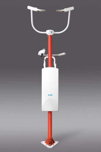
Precipitation intensity measurement0.00 … 999.99 mm/h (0.00 … 39.37 in/h)
Technical data Measurement performance
Measurement range of MOR 5 ... 75 000 m (16 ft ... 46.6 mi) with 1, 3, and 10 min averaging Reporting uncertainty ±10 % range 5 ... 10 000 m (16 ft … 6.2 mi) ±20 % range 10 000 ... 75 000 m (6.2 … 46.6 mi)
Operating principle Forward scatter measurement Scattering angle 42° Light source Near-infrared LED Spare parts and accessories Calibration set FSA11 Background luminance sensorLM21 Battery backup FSB101 Modem for long distance communication (> 1 km / 0.6 mi) DMX501 Obstruction light FS11OBS Transformer FS45002SP Calibration set PWA12 Maintenance cable QMZ101 Calibration set PWA12 Maintenance cable QMZ101
Precipitation amount measurement0.00 … 99.99 mm (0.00 … 3.94 in)
Amount of new snow 0.00 … 999 mm (0.00 … 39.33 in)
Mechanical specifications
Scatter measurement accuracy±3 % Weather measurement performance Weather type identification 7 different types of precipitation (rain, freezing rain, drizzle, freezing drizzle, mixed rain/snow, snow, ice pellets) Precipitation (unknown type) Fog (mist), haze (smoke, sand) or clear Weather type reporting WMO 4680 (SYNOP), 4678 (METAR), and NWS code tables; 49 different codes supported from the WMO 4680 code table
Compliance EMC compliance Electrical safety IEC/EN 61010 1 EMC immunity EN 61326 1, industrial environment EMC emissions EN 55032:2012, Class B EN 61000-3-2 EN 61000-3-2
Precipitation detection sensitivity0.05 mm/h (0.0020 in/h) or less, within 10 minutes
Weight, including Frangible Mast FSFM250 52 kg (115 lb) Mast Frangible and hinged glass fiber mast
Directives EU directives and regulations RoHS Directive (2011/65/EU) amended by 2015/863 EMC Directive (2014/30/EU) Low Voltage Directive (2014/35/EU)
Compliance marks CE, RCM, UKCA
www.vaisala.com 111
Optical specifications
Dimensions (H × W × D) 2.8 × 0.9 × 1.0 m (9.19 × 2.95 × 3.28 ft) Weight without mast 37 kg (81.57 lb)
Overvoltage category CATII Output data Automatic or polled visibility and sensor status data message with selectable message interval
Battery backup option Battery 2 Ah, typical backup time 30 min at 25 °C (77 °F) and 5 min at −40 °C (−40 °F) Outputs Serial data line RS-232 or optoisolated RS-485 (2-wire) or optional data Separatemodemmaintenance line RS-232 +12 VDC max. 800 mA output for option powering
Operating environment Operating temperature −40 ... +65 °C (−40 ... +149 °F) −55 ... +65 °C (−67 ... +149 °F) (optional) Operating humidity 0 … 100 %RH Wind speed Up to 60 m/s (134 mph) Maximum operating altitude 3000 m (approx. 9800 ft) Pollution degree 2 IP rating IP66 Inputs and outputs AC (mains) power supply 100/115/230 VAC ±10 %, 50 ... 60 Hz Power consumption Max. 300 VA (60 VA + 240 VA defrosting heaters)
LT31 Transmissometer Features •Single baseline for the MOR measurement range 10 … 10 000 m (33 … 32 800 ft) •State-of-the-art white light source •Automatic alignment with quality •Automaticcontrol calibration •Internal back-up battery •Compatible with TransmissometerVaisalaMITRAS and SKOPOGRAPH II Flamingo •Window •Sophisticated•Based•MeetscompensationcontaminationtheICAOandWMOrequirementsforRVRandvisibilityondecadesoffieldexperienceself-diagnostics
Accurate and reliable determination of runway visual range (RVR) reduces airport downtime and improves safety of operations. LT31 is the qualified observer of RVR providing correct visibility data without interruptions and with minimal maintenance.
White LED Provides Wide Spectrum Light Source LT31 incorporates a white LED as a light source. White light is needed for the best accuracy in transmittance measurement. The WMO recommends the use of a wide spectrum (white) light sources for transmissometers as narrow spectrum light source (for example, lasers or colored LEDs) will cause measurement error with some weather phenomena. 112
Vaisala Transmissometer LT31 enables accurate and reliable single baseline measurement for CATIIIb category airports.
Measurement Range from 10 to 10 000 m (33 to 32 800 ft) LT31 provides the most accurate and reliable solution for the automatic measurement of RVR. The meteorological optical range (MOR) measurement range is 10 ... 10 000 m (33 ... 32 808 ft), which covers the full required RVR range (CATI … CATIIIb), as well as the range required for aeronautical visibility (the ICAO-defined visibility). LT31 accuracy meets the ICAO and WMO requirements. This full measurement range is achieved with a single baseline system, which makes measuring easier and more economical.
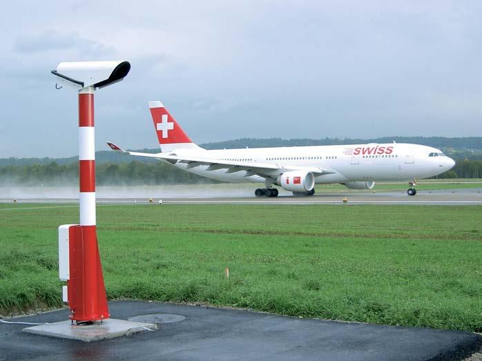
Automatic Systems
Calibration of a transmissometer is traditionally based on human observations. A reliable and accurate calibration has required very high visibility, stable conditions, and skilled and well trained personnel.
The integrated forward scatter sensor 113
The system automatically detects drift and adjusts the sensor settings accordingly. Weather conditions do not need to be as good as for manual calibration; LT31 automatically recognizes suitable conditions.
Automatic Fine Alignment
One of the major error sources in transmittance measurement is alignment drift. Checking and adjusting the alignment has also required skilled and trained personnel. To maintain the measurement accuracy, LT31 performs an automatic optimization of the alignment. The alignment quality is also continuously evaluated without any human intervention.
The Vaisala-patented automatic calibration method for transmissometers is based on an integrated forward scatter sensor/present weather sensor.
The automatic fine alignment also provides easy handling of LT31 during installation. The alignment quality during harsh weather conditions is ensured by a double mast construction. The outer tube works as wind and solar radiation shield. The inner support structure is separated from thermal and mechanical stress caused by solar radiation and wind load. Contamination Reduction In general, precipitation leads to an increased amount of window contamination. LT31 has long and narrow weather protection hoods that reduce the amount of window contamination caused by precipitation. For wind-driven precipitation or dust, the instrument is equipped with a powerful blower. The blower creates an air curtain in front of the instrument window. The air curtain is specifically designed not to disturb the measurement path and cause the measurement errors that have been a problem with conventional blower designs.
Automatic Calibration with Integrated Forward Scatter Sensor

Background Luminance Sensor
The optional LM21 sensor offers the means for measuring the ambient light level or background luminance in RVR applications. The background luminance sensor is used for measuring the background against which the runway lights or runway markings are seen. Airport runway lights at night 114
Up-to-date Data
True window
LT31 has a sophisticated self-diagnostics that provides detailed status information for all functional units. In addition, this feature helps to locate possible technical failures. It records a history of significant operational situations, warnings, and alarms from the instrument.
Extensive Self-diagnostics
Window contamination is a significant source of error in transmissometers. Maintaining high accuracy has required frequent cleaning. However, the effects of contamination can be automatically compensated if the window transmittance can be measured Inaccurately.LT31,window contamination is also compensated for by the most accurate method: by measuring the transmittance directly through the window glass.
Internal Backup Battery
LT31 can be equipped with an internal backup battery. It provides steady data availability during short power breaks, for example while backup generators are started.
Present Weather Reporting
windowscompensationcontaminationbasedonV-shaped
Automatic ContaminationWindowCompensation
The optional present weather reporting from RVR sites gives a full picture of the prevailing weather conditions within the entire airport area. The arrival of weather fronts and the presence of local showers can easily be monitored due to the multiple present weather observation points. The integrated present weather sensor provides the type and intensity of precipitation for METAR and local weather reporting purposes.
LM21
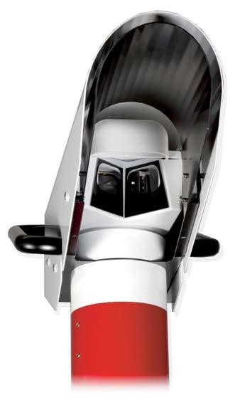
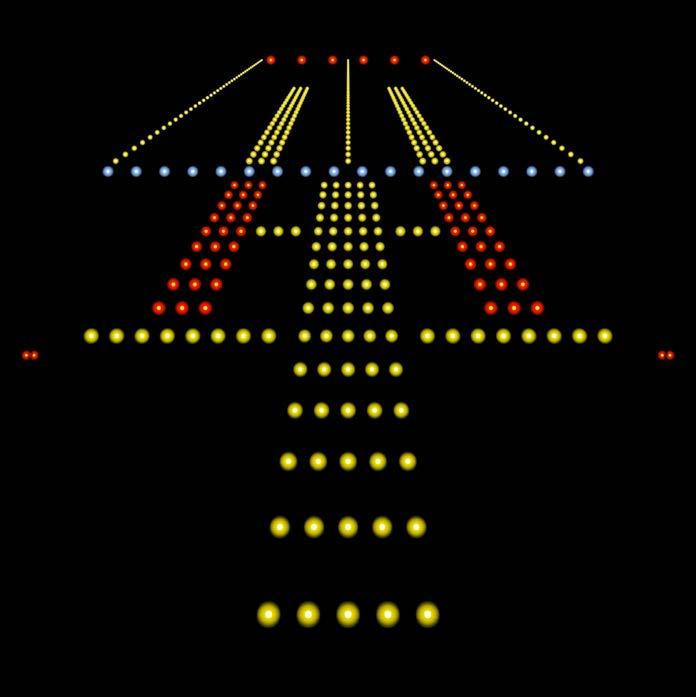
Present weather reporting option Identifies 7 different types of precipitation (rain, freezing rain, drizzle, freezing drizzle, mixed rain/ snow, snow, ice pellets) Reports 49 different codes from WMO 4680 code table
Transmitter optical specifications
Light source White light-emitting diode (LED)Certified class 1 product according to EN 60 825-1 Optical monitoring • Light source stability control •Windowcircmeasurementcontaminationandcompensationuitry
Purchased option 25 m (82 ft) baseline length 1/3 × baseline length to 10 000 m (32 808 ft) Accuracy (RVR range) Exceeds the ICAO (Annex 3) recommendations Output data •Automatic or polled data •Smessagestandardmessage including MOR, LT31 status and BGL data (option) •Message including present weather data (option) •MITRAS •FD12•SKOPOGRAPHcompatibletransmissometermessageIIFlamingotransmissometercompatiblemessageVisibilityMetercompatiblemessage
Transmittance measurement resolution20 bit Recommended baseline lengths 30 m (98 ft) baseline length (optimal)MOR: 10 … 10 000 m (33 … 32 808 ft) Transmittance range: < 0.01 % … 100 % 50 m (164 ft) baseline length MOR: 25 … 10 000 m (82 … 32 808 ft) Transmittance range: < 0.02 % … 100 % 75 m (246 ft) baseline length MOR: 37.5 … 10 000 m (123 … 32 808 <Transmittanceft)range:0.02%…100%
Maximum operating altitude 3000 m (9800 ft) Surge protectors 2000 m (6562 ft)
Pollution degree PD2 Inputs and outputs AC (mains) supply 115/230 V ±10 %, 50 ... 60 Hz Power consumption Max. 800 VA (for complete LT31 system) with all options
Obstruction light Optional Outputs Serial data line RS-232 or optoisolated RS-485 (2-wire) or optional data Separatemodemmaintenance line RS-232 Overvoltage category CAT WithIITermbox CAT III Mechanical specifications
Dimensions (H × W × D) 2685 × 420 × 1022 mm (105 71 × 16.54 × 40.24 in) Weight Transmitter unit LTT111 85 kg (187.39 lb) Receiver unit LTR111 82 kg (180.78 lb) IP rating IP66 mm [in] 1022 [40.24] [105.71]2685 [16.54]420 115
Technical Data Measurement performance
Battery backup option Battery 2.3 Ah, backup time 60 min at +20 °C (+68 °F) when a proper and fully charged battery is used
Operating environment Operating temperature -40 … +60 °C (-40 … +140 °F) -55standard…+60 °C (-67 … +140 °F) hood heater option Operating humidity 0 … 100 %RH Wind speed Up to 60 m/s (134 mph) Electrical safety IEC 60950-22 / EN 60950-22/A11 / IEC 60950-1 / EN 60950-1 / UL 60950-1
Compliance EU directives and regulations •Low Voltage •RoHS•EMC(2014/35/EU)DirectiveDirective(2014/30/EU)Directive(2011/65/EU) Compliance marks CE, RCM Electrical safety IEC 61010 1 Electromagnetic compatibilityIEC/EN 61326 1, industrial ENenvironment55032Class B, FCC 15B www.vaisala.com 116
Easy to Calibrate
Vaisala Background Luminance Sensor LM21 is an intelligent, standalone precision photometer.
Resembles Human Eye LM21 is a precision photometer with a verified photopic spectral response. It measures the total amount of light coming in from an angle of 6 degrees, and converts the measured data to cd/m2. The sensor sends the measurement data to the interface unit of a Vaisala transmissometer or forward scatter visibility sensor. The interface unit combines both the visibility and background luminance data into the same message and sends it to the main RVR LM21computer.canbeconnected to Vaisala Transmitter LT31 and Vaisala Forward Scatter Sensor FS11. LT31 and FS11 are connected using a RS-485 serial line.
The calibration of LM21 is traceable to international measurement standards for luminous intensity. Vaisala Field Calibrator LMA21 is a unique field calibration device that is available for quick field calibration. It provides a stabilized and diffused white light beam for LM21 calibration.
The optical path clearance monitoring circuitry verifies that measurement is not affected by obstructions.
Comprehensive SelfDiagnostics LM21 is an intelligent, standalone sensor. To ensure reliable and uninterrupted operation, it has extensive selfmonitoring functions with high power heating features. The sensor measures and compensates for the attenuation effect of window contamination. It ensures that measurement accuracy is maintained between window cleanings, and also extends the cleaning interval.
Vaisala Background Luminance Sensor LM21 is a state-of-the-art luminance sensor for runway visual range (RVR) assessment. The background luminance has an effect on the distance from which the pilot can see the runway lights.
The calibration coe cients for light intensity have been defined during factory calibration and stored in the LMA21 memory. Calibration starts automatically when LMA21 is connected to LM21. LM21 reads the calibration coe cients from the LMA21 memory and performs the calibration. The status and result of the calibration is displayed with 5 LED indicators on the cover of LMA21. LM21 measures the ambient light level or background luminance in RVR applications. In the picture, LM21 is installed on TransmissometerVaisalaLT31. 117
LM21 Background Luminance Sensor Features •Intelligent, standalone sensor • Verified accuracy and photopic •Extresponseensive self-diagnostics •Window •Field•Calibration•High•Opticalmeasurementcontaminationandcompensationpathblockagedetectionpowerheaterstopreventsnowaccumulationtraceabletomeasurementstandardscalibrationdeviceavailable
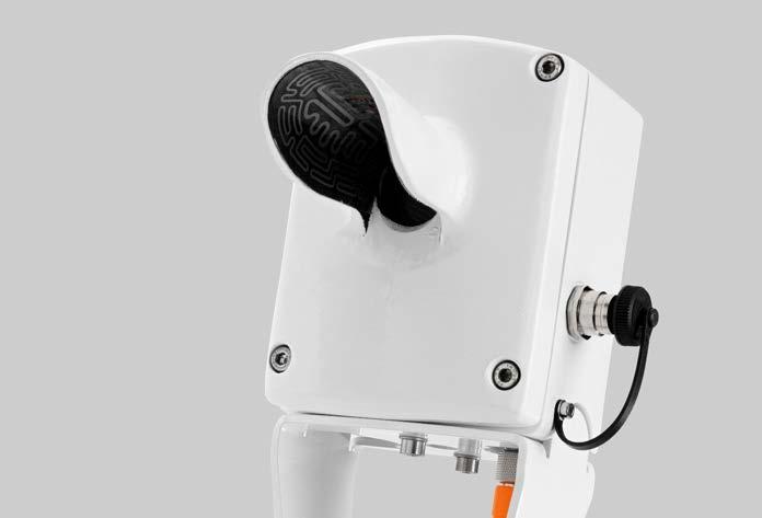
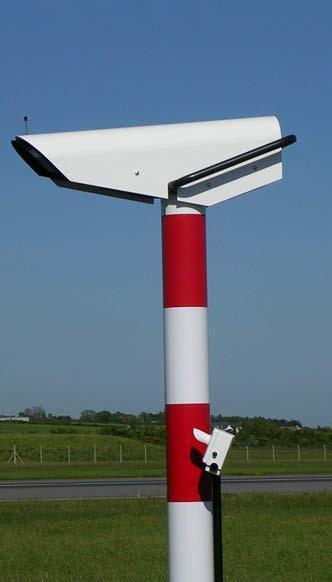
compliance LM21 sensor is CE compliant. The compliance has been verified according to the following EMC product family standards: Electrical equipment for measurement, control and laboratory useEMC Requirements IEC 61326-1: 2012-07 (Edition 2.0), Environment class: Industrial Electrical equipment for measurement, control and laboratory useEMC Requirements EN 61326-1: 2013-01 (Edition 2.0), Environment class: Industrial LM21 dimensions www.vaisala.com 118
Connection Power/signal cable provided Power supply 10 … 38 VDC, or alternatively 8 … 28 VAC, 6 W Heater power supply 28 VAC, 50 W Output signal RS-485 (RS-232), frequency output Overvoltage protection Power supply lines and output lines are protected by current limiting series resistors and transient suppressors
Technical Data Measurement performance
Operating environment Operating temperature -55 … +65 °C (-67 … +149 °F) Operating humidity 0 … 100 %RH
Measurement range 2 … 40 000 cd/m² Accuracy ±10 % Optical specifications Spectral response 400 … 700 nm, photopic according to CIE standards Peak wavelength 553 nm ± 5 nm Field of view 6° (94 % of measured luminance) Effective diameter of reception lens24 mm (0.94 in)
Mechanical specifications Weight 1230 g (2.71 lb) Cable length 2.3 m (7 ft 7 in) Color White Housing Aluminum, weatherproof Mounting With a mounting clamp onto LM21 Support Arm of LT31 or Optional Support Arm of FS11
Inputs and outputs
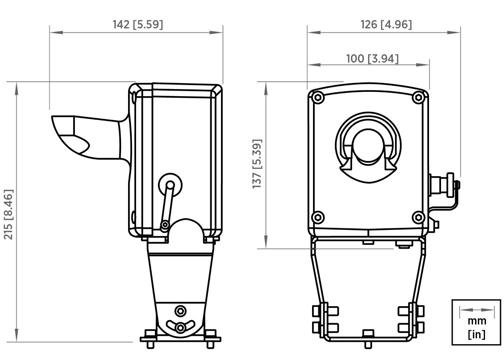
Accurate MeasurementVisibility
PWD10, PWD12, PWD20, and PWD22 Present Weather and Visibility Sensors Features All •Accuratemodels: and traceable measurement of prevailing •Compactvisibility and lightweight •Easy to AdditionallyinstallPWD12 and PWD22 models:•Indicate the cause of reduced •Identifyvisibilityprecipitation type •Measure the intensity and accumulation of precipitation •Estimate snow accumulation
Proven PrinciplesMeasurementforPresent Weather PWD12 and PWD22 identify precipitation type by accurately estimating the water content of precipitation with a capacitive device (Vaisala RAINCAPâ sensor element) and combining this information with optical forward scatter and temperature measurements. These three independent measurements are processed through sophisticated algorithms in order to produce an accurate evaluation of the weather type according to the WMO and NWS code tables.
119
Vaisala PWD series of present weather detectors and visibility sensors provide you o -the-shelf accuracy and reliability. They are a sensor family that grows with your needs. Thousands of Vaisala present weather and visibility sensors are installed around the world, working reliably and accurately in diverse applications and climates. In Vaisala PWD series, you find the mix you require of visibility measurement range (MOR), characterization of reduced visibility, precipitation type identification, precipitation NWSmeasurement,accumulation/intensityandreportformats(WMO,codetables).
Calibrated with reference to a highly accurate transmissometer, Vaisala PWD series sensors use the proven forwardscatter measurement principle to measure meteorological optical range (MOR). The visibility sensor is wellprotected against contamination: the optical components point downwards and hoods protect the lenses against precipitation, spray, and dust. This weather-proof design of PWD sensors provides accurate measurement results and reduces the need for maintenance. The optional hood heaters are recommended for wintry conditions to prevent ice and snow accumulation. Easy Installation PWD sensors are less than one meter long. All are compact, light-weight, come with a cable and connector for easy installation, and can be mounted in many ways on any existing mast.
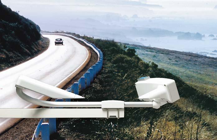
PWD12 is ideal for road weather applications. For Sophisticated Road Weather Applications PWD12 provides accurate visibility and present weather measurement in the road environment, where low visibility is a serious safety hazard and significantly reduces tra c flow rates. With a visibility measurement range of 10 … 2000 meters, Vaisala Present Weather Detector PWD12 is ideal for road weather applications. PWD12 also indicates the cause of reduced visibility to give you a full picture of weather conditions. Its ability to detect precipitation and identify precipitation type gives the road authority valuable information for the short-range planning of road maintenance operations.
PWD sensors can be used in planning road maintenance.
With a measurement range of 10 … 2000 meters, PWD10 offers economical and reliable visibility measurement for road weather applications. PWD10 is recommended for road weather systems that alert drivers to e.g. reduced visibility.
Wherever MeasurementVisibilityIsNeeded
With a measurement range of 10 … 20 000 meters, PWD20 offers longrange visibility measurement for diverse applications covering harbors, coastal areas, heliports, windmill parks – indeed, any locations or areas where visibility measurement is necessary.
With a visibility measurement range of 10 … 20 000 meters, PWD22 is a two-inone forward scatter visibility and present weather sensor. PWD22 is recommended for automatic weather stations, especially low-power ones that are used for general meteorological and aviation PWD22’sapplications.ability to detect freezing precipitation makes it possible to issue warnings when the weather presents safety hazards for road and air tra c. PWD22 is equipped with two Vaisala RAINCAPâ sensor elements to improve detection sensitivity during light precipitation events – even light drizzle is detected. PWD22 also reports present weather in WMO METAR code format so it is easily integrated with AWOS systems. PWD22 is recommended for automatic weather observation systems (AWOS).
Vaisala Present Weather Detector PWD22 120
Economical Visibility Measurement for Road Weather Applications
For Meteorological and Aviation Applications
PWD Sensor Applications
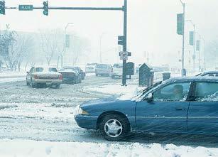
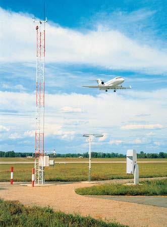
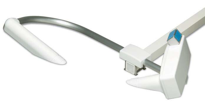
Weather type reporting WMO 4680 (SYNOP), 4678 (METAR) and NWS code tables; 49 different codes supported from WMO 4680 code table
Observation range of MOR 10 … 2000 m (32 … 6500 ft) Accuracy ±10 % at 10 … 2000 m (32 … 6500 ft)
PWD12 measurement performance
Amount of new snow 0.00 … 999 mm (0.00 … 39.33 in)
With optional luminance sensor: 5 W With optional hood heaters: 65 W Outputs Serial data line may be used either as RS 232 or RS 485 (2 wire) level 3signalsrelay controls (open collector)
Analog output current: 0 … 1 mA or 4 … 20 mA 8 m power/data cable standard. The PWD end is equipped with connector.
Operating principle Forward scatter measurement with 45° scattering angle Observation range of MOR 10 … 20 000 m (32 … 65 600 ft) Accuracy ±10 % at 10 … 10 000 m (32 … 32 800 ft) ±15 % at 10 … 20 km (2.6 … 12 mi)
Precipitation detection sensitivity0.05 mm/h (0.0020 in/h) or less, within 10 minutes
Operating humidity 0 … 100 %RH Maximum operating wind speed60 m/s (134 mph)
Average power consumption 3 W (peak 10 W)
PWD10 measurement performance
Precipitation intensity measurement0.00 … 999.99 mm/h (0.00 … 39.37 in/h)
Precipitation detection sensitivity0.05 mm/h (0.0020 in/h) or less, within 10 minutes
Weather type identification 4 different types of precipitation (rain, drizzle, mixed rain/snow, snow) Precipitation (unknown type) Fog (mist), haze (smoke, sand) or clear Weather type reporting WMO 4680 (SYNOP) and NWS code tables; 39 different codes supported from WMO 4680 code table
PWD22 measurement performance
Inputs and outputs
Power supply 12 … 50 V DC (electronics) 24 V AC or 24 V DC for heater option
PWD20 measurement performance
Auxiliary data Low visibility alarms in the data messages. 3 adjustable alarm limits to set the 3 relay controls. Hardware status (fail/warning) in the data messages. Third relay control output can also be driven by hardware status.
Technical data
Precipitation intensity measurement0.00 … 999.99 mm/h (0.00 … 39.37 in/h)
Operating principle Forward scatter measurement with 45° scattering angle Observation range of MOR 10 … 20 000 m (32 … 65 600 ft) Accuracy ±10 % at 10 … 10 000 m (32 … 32 800 ft) ±15 % at 10 … 20 km (2.6 … 12 mi)
Operating environment Operating temperature −40 … +60 °C (−40 … +140 °F)
Precipitation amount measurement0.00 … 99.99 mm (0.00 … 3.94 in)
Amount of new snow 0.00 … 999 mm (0.00 … 39.33 in)
Precipitation amount measurement0.00 … 99.99 mm (0.00 … 3.94 in)
Sun orientation Sunlight into the light receiver must be avoided IP rating IP66 121
Storage temperature −40 … +60 °C (−40 … +140 °F)
Operating principle Forward scatter measurement with 45° scattering angle
Operating principle Forward scatter measurement with 45° scattering angle Observation range of MOR 10 … 2000 m (32 … 6500 ft) Accuracy ±10 % at 10 … 2000 m (32 … 6500 ft)
Weather type identification 7 different types of precipitation (rain, freezing rain, drizzle, freezing drizzle, mixed rain/snow, snow, ice pellets) Precipitation (unknown type) Fog (mist), haze (smoke, sand) or clear
Technical Data Mechanical specifications Weight 3 kg (6.61 lb) Material Aluminum Dimensions (H × W × L) Dimensions Compliance EU directives and regulations EMC Directive (2014/30/EU) RoHS Directive (2011/65/EU) amended by 2015/863 Corrosion and salt mist VDA 621 415 EMC compatibility EMC emissions CISPR 32 / EN 55032, Class B Radiated susceptibility IEC 61000 4 3, 10 V/m Conducted susceptibility IEC 61000 4 6 EFT immunity IEC 61000 4 4 ESD immunity IEC 61000 4 2 Surge IEC 61000 4 5 Spare parts and accessories Item Code Pole Interfacemastunit with power supplies: 115/230 V AC Luminance sensor PWL111 Hood heaters for harsh winter conditions Support arm for mast installations Pole clamp kit for mast top installations Calibration set PWA12 Maintenance cable 16385ZZ Maritime insulator www.vaisala.com 122
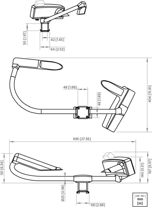
Wherever Visibility Measurement Is Needed
A special firmware ensures that flashing lights near the visibility sensor are not mixed with light pulses from the sensor. Thousands of PWD sensors are installed worldwide in demanding applications in all kinds of climates. They are installed on wind turbines both onshore and offshore.
The conditions on top of a wind turbine require a robust device, like PWD20W. Its performance and reliability have proven to be top-class. The hood heaters prevent ice accumulation on the device.
The FAA and other leading aviation authorities have placed their confidence in us. Our visibility sensor is also certified by Deutscher Wetterdienst. Especially for Wind Turbines Wind turbines are usually equipped with two red obstruction lights each. These obstruction lights flash at set intervals by day and night. Residents in the vicinity of a wind turbine complain of the brightness of the obstruction lights at night. Visibility data is used to control the intensity of these obstruction lights, thereby reducing the disturbance to the neighbours, yet not undermining aviation PWD20Wsafety.software has been specially designed for the wind turbine application. The infrared light emitted by obstruction lights may significantly disturb conventional visibility sensors. However, PWD20W filters out the intereference to eliminate the effect of obstruction lights on the visibility measurement. Red LED lights intefere with neither the visibility measurement nor the control of the lights.
With the help of PWD20W you can be in conformity with the regulations, such as the German General Administrative Regulation for the Marking and Lightning of Obstacles to Air Navigation. At the same time you can create a comfortable living environment for the surrounding community.
With PWD series sensors you get the best-in-class measurement performance and unparalleled reliability.
Our failure rate statistics indicate a mean time between failures (MTBF) clearly in excess of 20 years. You will also benefit from our fast delivery.
With a measurement range of 10 to 20 000 meters (32 to 65 600 feet), PWD20W offers long-range visibility measurement for onshore and offshore obstruction lights, offshore obstruction lights for vessels, met mast equipment. The standard model PWD20 can be used in diverse applications covering harbors, coastal areas, heliports, wind parks –indeed, any locations or areas where visibility measurement is necessary. 123
PWD20W is a visibility sensor with a special algorithm designed for wind turbine installations. Limit Your Light Emissions Flashing lights can be disturbing so it is smart to dim them to the optimal level.
PWD20W Visibility Sensor Features • Certified by •Easy•Mean•Unique•Robust•Hood•AWetterdienstDeutscherccurateandtraceablemeasurementofprevailingvisibilityheaterspreventiceaccumulationandversatilealgorithmensuresnoflickerinterferencetimebetweenfailures(MTBF)inexcessof20yearsinstallation
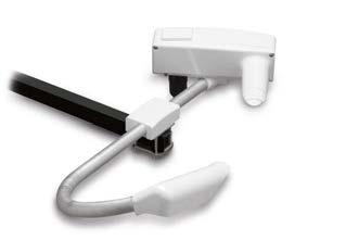
Technical Data
Operating principle Forward scatter measurement with 45° scattering angle
Conducted susceptibility IEC 61000 4 6 EFT immunity IEC 61000 4 4 ESD immunity IEC 61000 4 2 Surge IEC 61000 4 5
Sun orientation Sunlight into the light receiver must be avoided IP rating IP66 Inputs and outputs Power supply 12 … 50 V DC (electronics) 24 V AC or 24 V DC for heater option
Auxiliary data Low visibility alarms in the data messages. 3 adjustable alarm limits to set the 3 relay controls. Hardware status (fail/warning) in the data messages. Third relay control output can also be driven by hardware status. Mechanical specifications Weight 3 kg (6.61 lb) Material Aluminum Dimensions (H × W × L) 140 × 404 × 695 mm (5.51 × 15.91 × 27.36 in)
PWD20 measurement performance
Operating temperature −40 … +60 °C (−40 … +140 °F) Storage temperature −40 … +60 °C (−40 … +140 °F)
Observation range of MOR 10 … 20 000 m (32 … 65 600 ft)
Spare parts and accessories Item Code Pole Interfacemastunit with power supplies: 115/230 V AC Interface unit with power supplies, transient protection and relays: 230 V AC Luminance sensor PWL111 Hood heaters for harsh winter conditions Support arm for mast installations Pole clamp kit for mast top installations Calibration set PWA12 Maintenance cable PWDRSCABLE Maritime insulator www.vaisala.com
Operating environment
Corrosion and salt mist VDA 621 415 EMC compatibility EMC emissions CISPR 32 / EN 55032, Class B Radiated susceptibility IEC 61000 4 3, 10 V/m
Accuracy ±10 % at 10 … 10 000 m (32 … 32 800 ft) ±15 % at 10 … 20 km (2.6 … 12 mi)
Operating humidity 0 … 100 %RH Maximum operating wind speed60 m/s (134 mph)
Average power consumption 3 W (peak 10 W) With optional luminance sensor: 5 W With optional hood heaters: 65 W Outputs Serial data line may be used either as RS 232 or RS 485 (2 wire) level 3signalsrelay controls (open collector) Analog output current: 0 … 1 mA or 4 … 20 mA 8 m power/data cable standard. The PWD end is equipped with connector.
124
Compliance EU directives and regulations EMC Directive (2014/30/EU) RoHS Directive (2011/65/EU) amended by 2015/863
PWD50 reports meteorological visibility reliably from 10 meters to 50 kilometers (from 32 feet to 31 miles).
Vaisala Visibility Sensor PWD50 answers these needs with a mixture of robustness, dependability, versatility, and reliability. PWD50 measures visibility from 10 m to 50 km (from 32 ft to 31 mi).
Dependable operation of automated observation networks is a must today. Maritime observing systems need to work in inhospitable environments and also meteorological institutes face tough productivity and performance prerequisites.
Accurate MeasurementVisibility
Versatility PWD50 architecture allows for easy integration to existing or newly designed systems in a cost-e cient manner. The sensor can be mounted on existing masts in many ways. The electrical interfaces are in a single cable. Versatility is further enhanced with various options, such as pole masts, a selection of mounting adapters, power supply cabinets, and a modem for long distance communication.
Thousands of PWD series sensors have been installed all around the world. They have undergone rigorous test programs. In the field, the sensors have demonstrated very low failure rates. They have proved their robustness in the harshest climates and most demanding conditions, ranging from offshore to desert and from airport to roadside.
125
Solid Track Record
Robust and Dependable
PWD50 Visibility Sensor Features •Accurate, traceable measurement of prevailing visibility •Versatile and easy to install •Easy to integrate •Robust and •Weather-proofdependabledesignreducesneedformaintenance
Calibrated with reference to a highly accurate transmissometer, PWD50 uses the proven forward-scatter measurement principle to measure meteorological optical range (MOR). The sensor optics are well-protected against contamination: the optical components point downwards, and hoods protect the lenses against precipitation, spray, and dust. This weather-proof design helps to sustain accurate measurement results.
The downward-facing sensor hoods protect the optical surfaces from contamination, resulting in low maintenance needs and costs. The optional hood heaters prevent the build-up of ice and/or snow in the optical path.
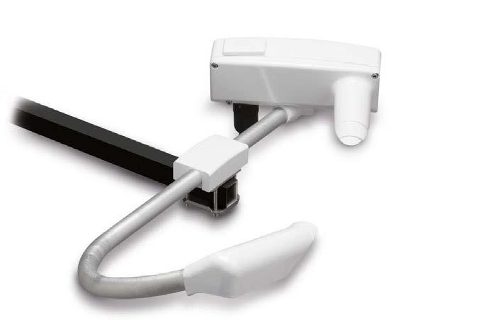

InDimensionsadditionto meteorological observation networks, PWD50 is also well-suited for use in offshore operations. www.vaisala.com
Observation range of MOR 10 … 50 000 m (32 … 164 000 ft) Accuracy ±10 % at 10 … 10 000 m (32 … 32 800 ft) ±20 % at 10 … 50 km (6.2 … 31 mi)
Average power consumption 3 W (peak 10 W) With optional luminance sensor: 5 W With optional hood heaters: 65 W Outputs Serial data line may be used either as RS 232 or RS 485 (2 wire) level 3signalsrelay controls (open collector) Analog output current: 0 … 1 mA or 4 … 20 mA 8 m power/data cable standard. The PWD end is equipped with connector.
Operating environment Operating temperature −40 … +60 °C (−40 … +140 °F) Storage temperature 40 … +60 °C (−40 … +140 °F)
Sun orientation Sunlight into the light receiver must be avoided IP rating IP66 Inputs and outputs Power supply 12 … 50 V DC (electronics) 24 V AC or 24 V DC for heater option
Operating principle Forward scatter measurement with 45° scattering angle
Technical data
PWD50 measurement
Spare parts and accessories Item Code Pole Interfacemastunit with power supplies: 115/230 V AC Luminance sensor PWL111 Hood heaters for harsh winter conditions Support arm for mast installations Pole clamp kit for mast top installations Calibration set PWA12 Maintenance cable 16385ZZ Maritime insulator
Operating humidity 0 … 100 %RH Maximum operating wind speed60 m/s (134 mph)
Corrosion and salt mist VDA 621 415 EMC compatibility EMC emissions CISPR 32 / EN 55032, Class B Radiated susceptibility IEC 61000 4 3, 10 V/m Conducted susceptibility IEC 61000 4 6 EFT immunity IEC 61000 4 4 ESD immunity IEC 61000 4 2 Surge IEC 61000 4 5 Mechanical specifications Weight 3 kg
126
L) 140
performance
Auxiliary data Low visibility alarms in the data messages. 3 adjustable alarm limits to set the 3 relay controls. Hardware status (fail/warning) in the data messages. Third relay control output can also be driven by hardware status. Directive (2014/30/EU) RoHS Directive (2011/65/EU) amended by 2015/863 (6.61 (H × W × × 404 × 695 mm (5.51 × 15.91 × 27.36 in)
Compliance EU directives and regulations EMC
lb) Material Aluminum Dimensions

Solid Track Record
Proven PrinciplesMeasurement
Thousands of PWD series sensors have been installed all around the world. They have undergone rigorous test programs. In the field, PWD sensors have demonstrated very low failure rates. They have proved their robustness in the harshest climates and most demanding conditions, ranging from offshore to desert and from airport to roadside. 127
Accurate MeasurementVisibility
PWD52 Present Weather Detector Features •Accurate, traceable measurement of prevailing visibility •Detects precipitation type •Measures the intensity and accumulation of precipitation •Estimates snow accumulation •Robust and •Easy•Weather-proofdependabledesignreducesneedformaintenancetoinstall,easytointegrate
Calibrated with reference to a highly accurate transmissometer, PWD52 uses the proven forward scatter measurement principle to measure meteorological optical range (MOR). The sensor optics are well-protected against contamination: the optical components point downwards and hoods protect the lenses against precipitation, spray, and dust. This weather-proof design helps sustain accurate measurement results.
PWD52 identifies precipitation type by accurately estimating the water content of precipitation using Vaisala RAINCAPâ sensor element, and combines this information with optical forward scatter and temperature measurement. These three independent measurements are processed through sophisticated algorithms to produce an accurate evaluation of the precipitation type according to the WMO and NWS code tables. Robust and Dependable Three measurement methods are used in PWD52 continuously, independently, and simultaneously, which reduces false alarm rates to a minimum. The identification of precipitation type is reliable due to sophisticated algorithmic processing of complementary data from multiple sources. These factors together produce exceptionally dependable data.
The downward-facing sensor hoods protect the optical surfaces from contamination, resulting in low maintenance needs and costs. The optional hood heaters prevent the build-up of ice and/or snow in the optical path.
PWD52 provides a wide visibility measurement range and accurate present weather reporting. Automated observation networks need to operate with maximum reliability. Maritime and aviation observing systems need to operate in extremely harsh conditions. Meteorological institutes face challenging productivity and performance requirements. Vaisala Present Weather Detector PWD52 answers these needs with a mixture of robustness, dependability, versatility, and reliability.
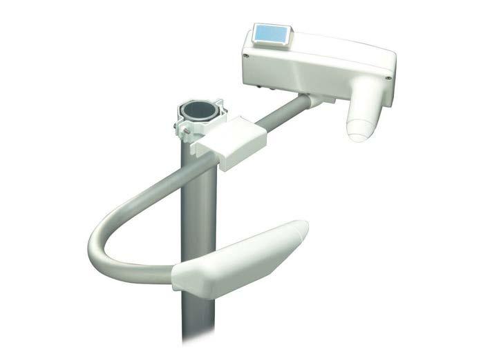
Weather type identification 7 different types of precipitation (rain, freezing rain, drizzle, freezing drizzle, mixed rain/snow, snow, ice pellets) Precipitation (unknown type) Fog (mist), haze (smoke, sand) or clear Weather type reporting WMO 4680 (SYNOP), 4678 (METAR), and NWS code tables; 49 different codes supported from the WMO 4680 code table
Inputs and outputs
Corrosion and salt mist VDA 621 415 EMC compatibility EMC emissions CISPR 32 / EN 55032, Class B Radiated susceptibility IEC 61000 4 3, 10 V/m Conducted susceptibility IEC 61000 4 6 EFT immunity IEC 61000 4 4 ESD immunity IEC 61000 4 2 Surge IEC 61000 4 5
Precipitation intensity measurement0.00 … 999.99 mm/h (0.00 … 39.37 in/h) Precipitation amount measurement0.00 … 99.99 mm (0.00 … 3.94 in)
Weight 3 kg (6.61 lb) Material Aluminum Dimensions (H × W × L) 167 × 404 × 695 mm (6.57 × 15.91 × 27.36 in) Compliance EU directives and regulations EMC Directive (2014/30/EU) RoHS Directive (2011/65/EU) amended by 2015/863
Observation range of MOR 10 … 50 000 m (32 … 164 000 ft) Accuracy ±10 % at 10 … 10 000 m (32 … 32 800 ft) ±20 % at 10 … 50 km (2.6 … 31 mi)
Auxiliary data Low visibility alarms in the data messages. 3 adjustable alarm limits to set the 3 relay controls. Hardware status (fail/warning) in the data messages. Third relay control output can also be driven by hardware status.
Mechanical specifications
Technical data PWD52 measurement performance
Amount of new snow 0.00 … 999 mm (0.00 … 39.33 in)
Power supply 12 … 50 V DC (electronics) 24 V AC or 24 V DC for heater option
Precipitation detection sensitivity0.05 mm/h (0.0020 in/h) or less, within 10 minutes
Operating principle Forward scatter measurement with 45° scattering angle
Operating environment
Operating temperature −40 … +60 °C (−40 … +140 °F) Storage temperature −40 … +60 °C (−40 … +140 °F)
Spare parts and accessories Item Code Pole Interfacemastunit with power supplies: 115/230 V AC Luminance sensor PWL111 Hood heaters for harsh winter conditions Support arm for mast installations Pole clamp kit for mast top installations Calibration set PWA12 Maintenance cable 16385ZZ Enhanced weather detection option Maritime insulator Dimensions
www.vaisala.com 128
Average power consumption 3 W (peak 10 W) With optional luminance sensor: 5 W With optional hood heaters: 65 W Outputs Serial data line may be used either as RS 232 or RS 485 (2 wire) level 3signalsrelay controls (open collector) Analog output current: 0 … 1 mA or 4 … 20 mA 8 m power/data cable standard. The PWD end is equipped with connector.
Operating humidity 0 … 100 %RH Maximum operating wind speed60 m/s (134 mph) Sun orientation Sunlight into the light receiver must be avoided IP rating IP66
Vaisala DRD11A Rain Detector detects rain and snow quickly and accurately. It uses droplet detection instead of signal level threshold.
DRD11A Rain Detector Features and accurate precipitation detection (ON/OFF) intensity measurement with processing unit element for keeping sensor free of snow and condensed moisture, and for quick
•Maintenancedrying free
DRD11Arain.also
•Heating
•Fast
A delay circuitry allows a two-minute interval between raindrops before assuming the OFF position (no rain). This enables the sensor to accurately distinguish between rain cessation and light features an analog rain signal for estimating rain intensity. Since this signal is proportional to the percentage of moist or wet area on the sensor plate, rain intensity has a direct impact on the amplitude and variation of this analog signal.
The DRD11A sensor is positioned at a 30° angle. The design together with the internal heating element ensure that the surface dries quickly. This is an essential factor for calculating intensity. The same heating element also protects the surface from fog and condensed moisture. It activates at low temperatures to melt snow and allow snow detection. Sensor performance is not affected by reasonable amounts of dirt and dust due to droplet detection.
•Rain
The low heating power model DRD11L is designed for areas with only rain or wet and moist snow precipitation. 129
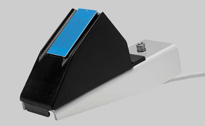
â 2 Polyurethane moisture shield 3 Component assembly 4 Wind shield 5 Mounting plate
130
1)The actual power consumption depends on the temperature and rain intensity. Mechanical specifications Weight 0.5 kg (1.1 lb) Cable length 4 m (13 ft 1 in)
Detection delay < 0.1 ms OFF delay (active) < 5 min Sensor plate Sensing area 7.2 cm2 (1.12 in2) Angle 30° Inputs and outputs Operating voltage 12 V DC, ±10 % Average power consumption 0.30 W at 12 V Maximum power consumption with sensor plate heating on 3.12 W at 12 V 1) Rain on/off output Open collector, active low signal corresponds to rain Maximum voltage 15 V Maximum current 50 mA Analog output 1 … 3 V (wet … dry) Frequency output 1500 … 6000 Hz, non calibrated Supply current Typical less than 150 mA Maximum 260 mA Heater off 25 mA Heating power, sensor plate 0.5 … 2.3 W Control for heater OFF OFF Connect to GND Contact rating Minimum 15 V, 2 mA
Technical Data
Measurement performance
[3.15]80 25 [0.98]52[2.05] 175 [6.89] mm[in] Dimensions 1 Sensor,
Sensor Capacitive principle, thick layer sensor RAINCAPâ, with a thin glass shield Integrated heater element Rain detection sensitivity Minimum wet area 0.05 cm2 (0.008 in2)
Ground wiring Separate ground wires for signal and heater Mounting By one screw (M5×20 mm) to sensor support arm Dimensions (H × W × L) With wind shield 110 × 80 × 175 mm (4.33 × 3.15 × 6.89 in) Without wind shield 90 × 46 × 157 mm (3.54 × 1.81 × 6.18 in) Materials Housing Polypropylene Windshield and support bracketAluminum Moisture shield Operating environment Operating temperature −15 … +55 °C (+5 … +131 °F) Storage temperature −40 … +65 °C (−40 … +149 °F) [1.85]47 RAINCAP www.vaisala.com
Polyurethane
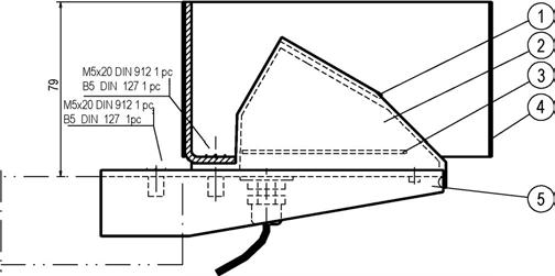
CL31 is fully automatic. In addition to cloud height data, the messages contain instrument status information based on comprehensive self-diagnostic routines. In case of malfunction, the diagnostics help users to identify the failed module. CL31 features practical modularity and its easy-access door ensures fast servicing and high data availability. Easy installation and maintenance CL31 is easy to install. It has a radiation shield that protects the unit during precipitation and against excessive heat or cooling in extreme temperatures. The automatic window blower with heater improves performance by keeping the window clean and dry. In cold conditions heating prevents frost generation on the window. Data messages •Cloud hits (up to 3 layers) and status information •Cloud hits, status, and backscatter •Emulationprofile of CT12K, CT25K, •SkyLD-25/40condition (optional)
Vaisala Ceilometer CL31 is a compact and lightweight instrument for cloud base height and vertical visibility measurements. It detects 3 cloud layers simultaneously. CL31 uses a pulsed diode laser LIDAR (light detection and ranging) technology. CL31 is ideal for aviation and meteorological applications.
131
beam can be directed either vertically or tilted. The tilting option together with the novel optics design provides enhanced performance during precipitation by improving the protection given by the shield. In the measurement unit, a tilt angle sensor automatically corrects the measured cloud distance reading to vertical cloud base height.
Ceilometer Features •Measurement range from 0 to 7.6 km (from 0 to
CL31 25
000 feet) •Modular design for easy installation and •Extensive•Latest•Reliable•Fast•Second-generation,maintenanceadvancedsingle-lensopticsprovidesexcellentperformancealsoatlowaltitudesmeasurementenablesdetectionofthincloudlayersbelowasolidcloudbaseoperationinallweather;unsurpassedperformanceinverticalvisibilityandclouddetectionduringprecipitationtechnologyfromtheworld-leadingmanufacturer-basedontheexperiencefrommorethan5000installedVaisalaceilometersworldwideself-diagnosticswithfaultanalysis
Measurement starts from ground level
The enhanced single-lens technology applied in CL31 ensures excellent performance starting at a height of virtually zero. This is due to the strong and stable signal over the whole measurement range. The single-lens technology provides unsurpassed reliability during precipitation, low clouds and ground based obscurations, which are the most critical phenomena in aviation safety. Fast measurement Fast measurement helps to detect thin cloud patches below a solid cloud base. CL31 provides a full backscatter profile for data visualization and research
Thepurpose.CL31
Extensive self-diagnostics
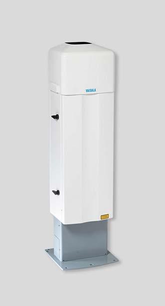
Measurement unit 15 W Internal heater 100 W Window conditioner heater 175 W Window blower 20 W Frequency (min/max) 50/60 Hz No-break power supply 12 V sealed lead-acid battery, 2 Ah Backup battery 12 V internal, 2 Ah Overvoltage protection Low-pass filter, VDR Overvoltage category II Interfaces Data •RS 232 • RS 485, multidrop, 2 wire •DXL421 modem module •LAN (Ethernet) interface option Maintenance RS 232 Baud rate RS 232 / RS 485 300 … 57 600 bps Modem V.21, V.22 300 … 1200 bps
Measurement
Attachment mechanics for radio modem antenna CLRADIOKIT Graphical User Interface for Ceilometers CL-VIEW Boundary Layer View Software for Ceilometers BL-VIEW Bird deterrent CL31BIRDKIT Air Quality Plug and Play Package for Ceilometer with laptop and preinstalled BL View
Operating temperature −55 … +55 °C (−67 … +131 °F), excluding battery Operating humidity 0 … 100 %RH Wind tolerance Up to 55 m/s (123 mph)
Electrical
Technical data
Operating environment
Operating voltage 115/230 V AC 100 – 127 V AC, 207 – 253 V AC Power consumption Power consumption (maximum)310 W
Cable termination box with extra transient protection Termbox-1200 PC maintenance cable QMZ101 Shock absorbing mounting pad for ship installations CT35022 Modem DXL421
www.vaisala.com 132
Measurement range 0 … 7.6 km (0 … 25 000 ft) Measurement resolution 10 m (33 ft) or 5 m (16 ft), selectable Reporting interval Programmable 2 … 120 s, or polling interval 2 s default Distance measurement accuracy against a hard target ±5 m (16 ft)
Vibration Lloyds Register / IEC 60068 2 6 5 … 13.2 Hz, ±1.0 mm 13.2 … 100 Hz, ±0.79 g 9.1 … 150 Hz, ±0.5 g Pollution degree 2
Tilt positions Vertical or 12° tilted Dimensions Measurement unit 620 × 235 × 200 mm (24.41 × 9.25 × 7.87 in) Height with radiation shield 1190 mm (47 in) Total 1190 × 335 × 324 mm (46.85 × 13.19 × 12.76 in) Weight Measurement unit 12 kg (26.5 lb) Radiation shield and blower 19 kg (41.8 lb) Total 31 kg (68 lb) Plywood transport container Container size 1400 × 490 × 450 mm (55 × 19.30 × 17.72 in) Container weight 47 kg (103.6 lb)
CLAQPACKAGE Compliance EU directives and regulations LVD, EMC, RoHS EMC immunity IEC/EN 61326 1, industrial environment EMC emissions CISPR 32 / EN 55032, Class B EN 61000-3-2 EN 61000-3-3 safety IEC/EN/UL/CSA 61010 1 Environmental IEC/EN 63000 Eye safety IEC/EN 60825-1:2014
Inputs and outputs
Compliance marks CE, RCM, China RoHS, UKCA
Mechanical specifications
Measurement performance
Maximum operating altitude 3000 m (approx. 9800 ft) IP rating IP65 (measurement unit) IPX6 (with radiation shield)
Spare parts and accessories
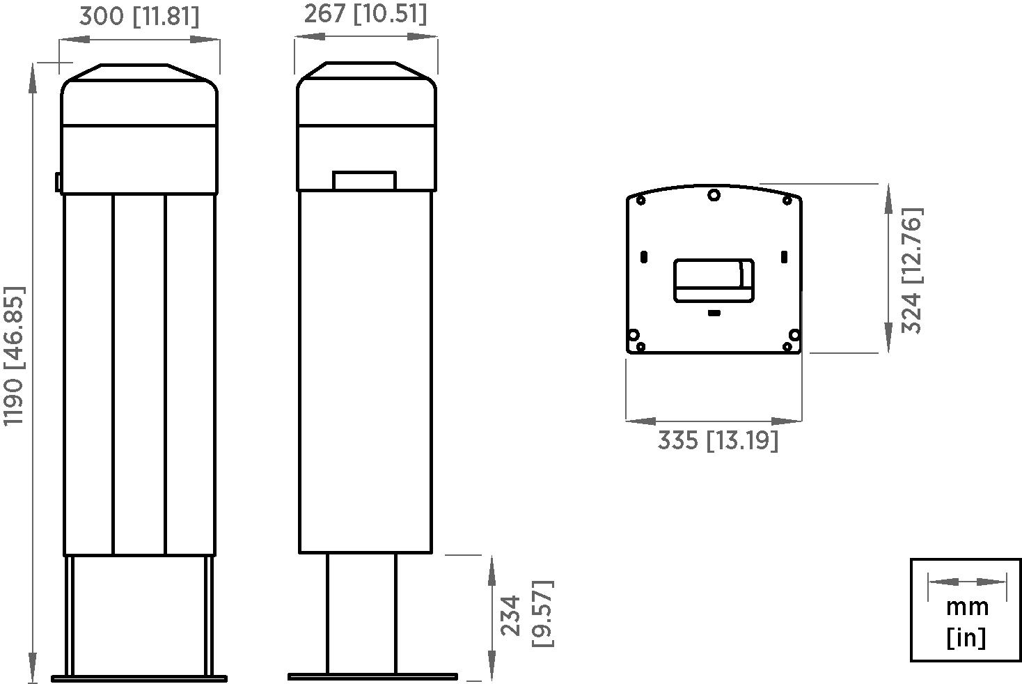
with fault •Reliableanalysisoperation in all weather: unsurpassed performance in •Basedprecipitationonrobust and
•Field-proven,
operation in all weather •Modularconditionsdesign for easy installation and maintenance •Extensive
The enhanced single lens technology applied in CL51 ensures excellent performance starting at a height of virtually zero. The signal is strong and stable over the whole measurement CL51range.is able to detect 3 cloud layers simultaneously. If the cloud base is obscured due to precipitation or groundbased fog, CL51 reports vertical visibility. CL51 is able to provide the backscatter profile over the full measurement range. This information provides a possibility for an advanced boundary layer and atmospheric analysis. Designed for harsh weather CL51 has a shield with a blower and heater, which allows steady operation in precipitation and under extreme temperatures. Reliable solar protection is ensured by optical filters. A tiltable shield further protects the instrument from precipitation and specular reflection from ice crystals. The tilt angle measurement and correction is automatic.
000 •Backscatterft) profiling
clouds •Latest
CL51 employs a pulsed diode laser LIDAR (light detection and ranging) technology, where short, powerful laser pulses are sent out in a vertical or near-vertical direction. The reflection of light (backscatter) caused by clouds, precipitation or other obscuration is analyzed and used to determine the cloud base height. Measurement from ground level
Self-diagnostics
• Emulation of CL31 and LD-40 condition (optional)
•Second-generation, advanced single-lens optics with excellent also at low altitudes fully automatic 24/7 self-diagnostics affordable laser diode of cirrus technology from the world leading manufacturer - over 5000 ceilometer installations
•Sky
Features reporting range up to 13 km (43 over full range up to 15 km (49 200 feet)
Vaisala Ceilometer CL51 is designed to measure high range cirrus cloud heights without surpassing the low and middle layer clouds, or vertical visibility in harsh conditions. 133
worldwide
•Clouddata hits, status, and backscatter profile
technology •Detection
performance
In addition to cloud height data, the fully automatic CL51 outputs messages with information on the instrument status. The information is based on comprehensive self-diagnostic routines. In case of a malfunction the diagnostics help the user to identify the failed module. Maintenance Periodic maintenance of CL51 is normally limited to window cleaning. There is no need for adjustments in the field. The automatic window blower with heater improves performance by keeping the window clean and dry. In cold conditions heating prevents frost generation on the window. Any malfunction is automatically reported in the data and status messages. Data messages
CL51 Ceilometer
•Cloud
•Cloud hits and internal monitoring
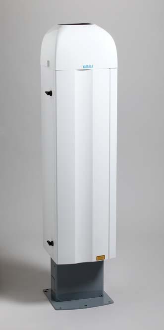
Technical data Measurement performance
Weight Measurement unit 18.6 kg (41 lb) Radiation shield and blower 27.4 kg (60.4 lb) Total 46 kg (101.41 lb)
Shipping weight Typically 75 kg (165.3 lb)
Height with radiation shield 1531 mm (60.28 in) Total 1531 × 335 × 324 mm (60.28 × 13.19 × 12.76 in)
Graphical User Interface for Ceilometers CL-VIEW Boundary Layer View Software for Ceilometers BL-VIEW Bird deterrent CL51BIRDKIT
www.vaisala.com 134
Spare parts and accessories Cable termination box with extra transient protection Termbox-1200 PC maintenance cable QMZ101 Shock absorbing mounting pad for ship installations CT35022 Modem DXL421 Attachment mechanics for radio modem antenna CL51RADIOKIT
Inputs and outputs Operating voltage 115/230 V AC 100 – 127 V AC, 207 – 253 V AC Power consumption (typical) 310 W Backup battery 12 V internal, 2 Ah Overvoltage category II Interfaces Data •RS 232 • RS 485, multidrop, 2 wire • DXL421 modem module • LAN (Ethernet) interface option Maintenance RS 232 Baud rate RS 232 / RS 485 300 … 115 200 bps Modem V.21, V.22 300 … 1200 bps Operating environment Operating temperature −55 … +55 °C (−67 … +131 °F) excluding battery Operating humidity 0 … 100 %RH Wind tolerance Up to 55 m/s (123 mph) Vibration Lloyds Register / IEC 60068 2 6 5 … 13.2 Hz, ±1.0 mm 13.2 … 100 Hz, ±0.7 g 9.1 … 150 Hz, ±0.5 g Pollution degree 2 Maximum operating altitude 3000 m (approx. 9800 ft) IP rating IP65 (measurement unit)
Mechanical specifications Dimensions Measurement unit 834 × 266 × 264 mm (32.83 × 10.47 × 10.40 in)
Plywood transport container Container size 1650 × 540 × 480 mm (65 × 21.26 × 18.90 in)
Air Quality Plug and Play Package for Ceilometer with laptop and preinstalled BL View CLAQPACKAGE Compliance EU directives and regulations LVD, EMC, RoHS EMC immunity IEC/EN 61326 1, industrial environment EMC emissions CISPR 32 / EN 55032, Class B EN 61000-3-2 EN 61000-3-3 Electrical safety IEC/EN/UL/CSA 61010 1 Environmental IEC/EN 63000 Eye safety IEC/EN 60825-1:2014 Compliance marks CE, RCM, China RoHS, UKCA
Measurement range 0 … 13 km (0 … 43 000 ft) Backscatter profiling range 0 … 15 km (0 … 49 200 ft) Reporting resolution 10 m (30 ft), units selectable Reporting cycle 6 … 120 s, or polling Distance measurement accuracy against a hard target ±5 m (16 ft)
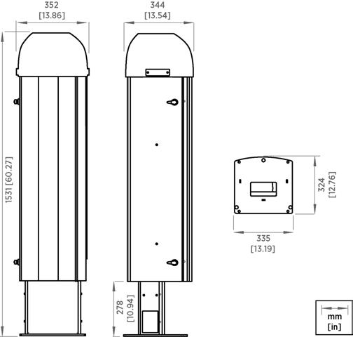
The improved high-resolution attenuated backscatter profiling is available for the full range, up to 15.4 km (9.6 mi).
Easy installation and maintenance CL61 is a compact and eye-safe lidar ceilometer with modern communication and network capabilities. The modular structure enables safe and easy installation by 1 person.
Features
•Measurementabsorption data available in netCDF
•Traceableformatfactory calibration Improved decision-making with more detailed view of atmospheric conditions CL61 uses attenuated backscatter profiles measured in 2 polarization directions to calculate the depolarization ratio. The depolarization measurement not only enables the liquid/solid differentiation, but also makes it possible to detect dust and volcanic ash.
•Unique single-lens optics with excellent performance also at low
•Attenuatedashbackscatter profiling for the full range of up to 15.4 km (9.6 •Improvedmi) signal-to-noise ratio (SNR) for enhanced atmospheric structure reporting
•Depolarization measurement to support differentiation,liquid/solidaswell as detection of potential dust and volcanic
To further enhance atmospheric structure reporting, CL61 has an improved signal-to-noise ratio (SNR).
Vaisala Lidar Ceilometer CL61 is a high-performance light detection and ranging (LiDAR) instrument with depolarization measurement capable of unattended operation 24/7 in all conditions. The depolarization measurement enables di erentiation between solid, liquid, or mixed-phase clouds and precipitation, providing ready-to-use information for atmospheric characterization.
Vaisala'sworldwide.unique and proven single-lens technology guarantees reliable measurements in low altitudes.
135
The system is able to internally buffer data to smooth out brief communication inconsistencies. Data is labeled with time, based on a clock synced using Network Time Protocol.
•Patentedaltitudes technology to minimize the effect of water vapor
The new patented transmitter technology in CL61 minimizes the effect of water vapor absorption. Single-receiver depolarization measurement does not require field calibration. Portable and versatile data Measurement data is available in the universal and accessible netCDF format, making data sharing easy with colleagues and other users.
With these enhanced features and BL View software, you also get a detailed view of atmospheric conditions within the planetary boundary layer, for example, for air quality forecasting. Leading technology CL61 contains the latest technology from the world-leading manufacturer with strong experience in lidar technology since the 1980s. There is an installed base of thousands of Vaisala ceilometers
The product has low maintenance requirements, with extensive selfdiagnostics and embedded fault analysis minimizing downtime. Remote Ethernet access reduces the need for site visits and interruption of measurement data flow. These benefits contribute to overall low cost of ownership. Integrated security software keeps your instrument and data safe.
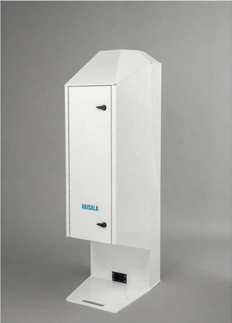

1)Available later. Inputs and outputs Nominal voltage 120 / 230 V AC 3.1 / 1.6 A Operating voltage 90 – 130 / 200 – 250 V AC Overvoltage category CAT III Operating frequency 50 … 60 Hz Data interface Ethernet (> 10 Mbit/s) Maintenance interface Ethernet Message format NetCDF Power consumption With heating Max. 370 W Without heating Max. 100 W Mechanical specifications Dimensions (H × W × L) 1400 × 420 × 512 mm (55.12 × 16.54 × 20.16 in) Weight, total 55 kg (121 lb) Weight, radiation shield 23 kg (51 lb) Weight, interface unit 12 kg (26 lb) Weight, measurement unit 20 kg (44 lb) Material Aluminum Color White (RAL9003) Coating Multi-layer coating to prevent environmental corrosion Tilt angle Default: 3° 420 [16.54] [55.12]1400 512 [20.16]mm[in] CL61 dimensions Operating environment IP rating (when inside radiation shield, excluding window blower) IP66 Operating temperature −55 … +55 °C (−67 … +131 °F) Storage temperature −55 … +60 °C (−67 … +140 °F) Operating humidity 0 … 100 %RH Wind Up to 60 m/s (134 mph) Compliance EMC immunity EN 61326 1, industrial environment EMC emissions CISPR 32 / EN 55032, Class B Electrical safety IEC / EN 61010 1 1) Eye safety Class 1M IEC / EN 60825 1:2014 Compliance marks CE, China RoHS, RCM, UKCA Complies with ICAO frangibility requirements.
Technical data Measurement performance Measurement range, cloud and backscatter 0 … 15 400 m (0 … 50 500 ft) Reporting resolution 4.8 m (15.7 ft) Measurement interval 5 s Measurement accuracy against hard target ±5 m (16.4 ft) Laser InGaAs diode Laser wavelength 910.55 nm Data reporting Atmospheric parameters Cloud base heights (up to 5 layers) Cloud depth and penetration 1) Precipitation/fog detection 1) Sky condition Atmospheric profiles Attenuated backscatter profile Parallel and cross-polarized profiles Depolarization ratio profile
1)IEC / EN / UL / CSA 61010 1 available later. www.vaisala.com 136
Status information monitoring data
Internal
CL-VIEW Graphical User Interface Features
•Cloud base data and backscatter profiles in clear graphical form
•A large variety of user selections
CL-VIEW has an internal terminal program that can be used to check the ceilometer status and change the internal parameters of the ceilometer. 137
•Maintenance access through internal terminal program
Vaisala CL-VIEW o ers an improved graphical interface for ceilometer users.
on a computer with Microsoftâ Windowsâ 10, providing all conveniences of a graphical user interface. Menus, option screens, icons, and help texts make the program easy and fast to use. Communication between the ceilometer and the computer is arranged through a direct RS-232 serial line or through a modem in longer CLdistances.-VIEWis designed to be optimal for receiving, storing, visualizing, and analyzing data. The software is very flexible, and it can be tailored to suit operators' needs. The graphical presentations include cloud detection, cloud intensity, and backscatter profile graphs. Numerical cloud height information, ceilometer status, and log status along with time and date are also displayed in all three graphs.
•Displays and logs data from one or more ceilometers while running other Windows applications
If the ceilometer is equipped with the sky condition option, this message content can be viewed in the main window or a separate window. It provides cloud layer height and information in textual or symbolic format.
• Viewing of previously logged data is possible while logging and displaying real-time data
•Sky condition window
Vaisala Graphical User Interface for Ceilometers CL-VIEW is an independent data collection, storage, and presentation software designed for Vaisala CL51, CL31, CT25K, and CT75K Laser Ceilometers. Ceilometer models CT12K and LD40 are also partially CL-VIEWsupported.runs
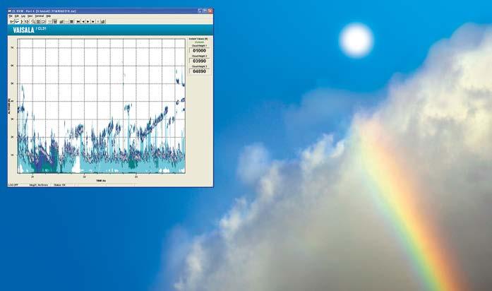
Minimum system requirements Operating system Microsoftâ Windowsâ 10 Memory 32 MB RAM Hard disk space 50 MB www.vaisala.com 138
Technical data
The cloud intensity is shown as a point graph where the color is proportional to the strength of the return signal from the altitude in question. The backscatter profile is presented as a line graph in instant and average modes. Both modes can be displayed simultaneously. The sky condition window presents cloud layer height information and the corresponding sky condition in textual, numerical, or graphics format.
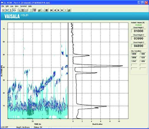
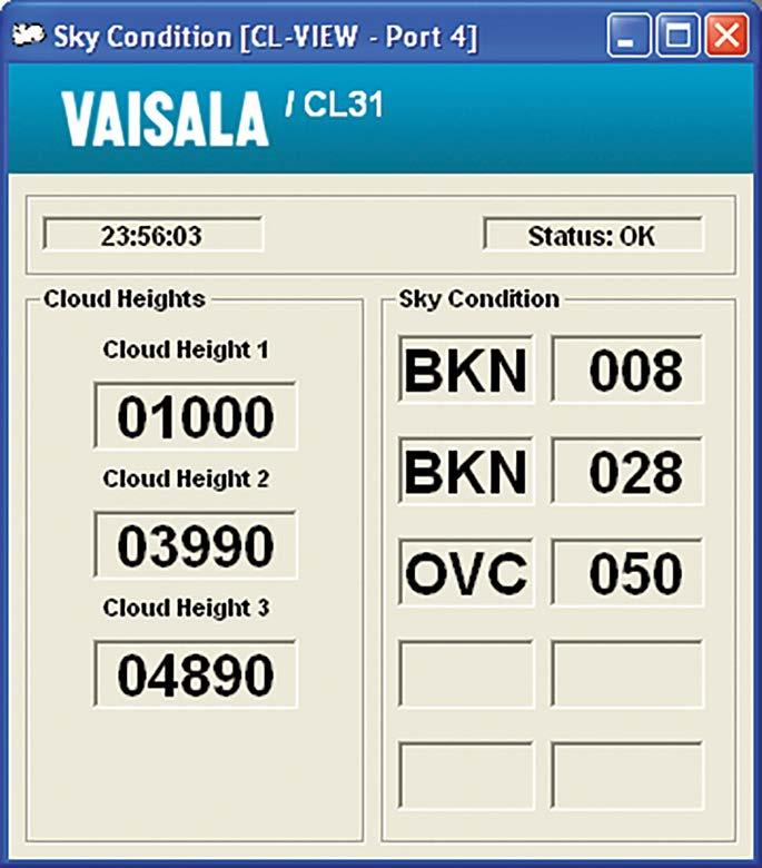
•Seamless integration of data for external applications, forecasting, and numerical model verification
•Centralized view to data from up to 10
•Completeceilometersviewof MLH, clouds, and full-range backscatter profile
•24/7 visualization of mixing layer height (MLH) evolution and additional layers
Fast data analysis
BL‑View Boundary Layer View Software Features
•Hourly average MLH
The ceilometer messages are stored in the netCDF format on the computer hard drive for fast data analysis and easy sharing. The automatically analyzed boundary layer data can be easily transferred to other applications, for example, as inputs to numerical weather prediction models.
139
Vaisala BL-View is an application software for the data collection, analysis, and visualization of the planetary boundary layer. It provides an understanding of the current conditions to support faster and more reliable decision-making.
Flexible user interface
Improved decision-making with accurate boundary layer visualization
You can run simultaneous operatorspecific analyses with user-set algorithm parameters for both logged and online data without disturbing online data
Theanalysis.ceilometer and communication status is displayed on the main screen enabling easy investigation of possible operational alerts. The warnings and alarms are stored automatically to log files for easy retrieval.
To ensure reliable reporting in all weather conditions, BL-View uses an all-weather algorithm that takes into account precipitation and cloud events. The algorithm also uses the time of day and the location to improve automatic reporting in all conditions. Manage your ceilometer network BL-View provides a centralized view of the ceilometer data in the network, facilitating concentrated data analysis.
•Easy sharing, viewing, and analysis of data between independent BL View users
Reliable data in all weather
The analysis uses an automatic algorithm for the online reporting of the boundary layer depth and additional residual structures. BL-View calculation is based on the combined gradient and idealized backscatter methods and enables reliable automatic reporting of the convective MLH.
File Viewer enables a simple and convenient way to analyze any netCDF files logged with BL-View.
Vaisala ceilometer measures the backscatter profile of the atmosphere and provides it for analysis in BL-View.
The status information of the network is available in one place. For a network with more than 10 ceilometers, Vaisala recommends using BL-View with Vaisala Observation Network Manager NM10.
BL-View generates an online visual representation of the mixing layer height (MLH), which provides you with an immediate understanding of the local conditions. You can view and analyze logged data while continuing to display online data. BL-View helps to improve your air quality monitoring and forecasting.
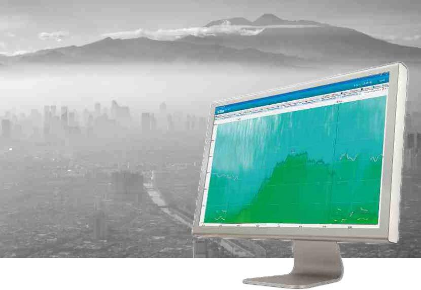
Technical data Measurements and observations Measured parameters Cloud height data Backscatter intensity Calculated parameters Mixing layer height 1-hour average mixing layer height 2 ... 4 additional elevated layers Negative gradient profile Quality index Cloud base height 3 height values Update interval 1 minute Measurement range MLH data, CL31, CL51 and CL61Up to 4000 m (13 120 ft) Profile data, CL31 Up to 7700 m (25 260 ft) Profile data, CL51 and CL61 Up to 15 400 m (50 520 ft) Inputs and outputs Supported devices CL6CL5CL3111 Connection capacity 1 ... 10 Vaisala ceilometers Connection options, ceilometer/ BL View TCPTCPUDPSerialclientserver Input file format DnetCDFAT(Vaisala proprietary) Output file format HISnetCDF(Vaisala proprietary) PNG Minimum system requirements Computer connection optionsEthernet port Serial port USB serial converter Operating system Microsoft® Windows® 10 Memory 2 GB RAM Hard disk space 1) For BL-View installation 600 MB For BL-View data files 40 GB / year / ceilometer (typically) 1)Required total hard disk space depends on the number of ceilometers. User interface features File viewer for shared netCDF files Zooming of plots Scheduled snapshot Selectable algorithm (gradient, profile fit, merged gradient and profile fit) User-selectable algorithm parameters Import (DAT files) Alerts Device-specificview configuration Management of your ceilometer network User-selectable units (meters/feet) User interface languages: •Chinese•English Algorithm performance verified by radiosondes www.vaisala.com 140

141
Features •WMO and ICAO compliant •Data output rate 4 Hz and 8 Hz •Stainless steel •Measurement•Fully•Data•3-transducer•Maintenance-freestructurelayoutprovidesaccuratedataformatoutputs:polarcoordinatesandvectorscompensateseffectsoftemperature,humidity,andpressurerangeupto90 m/s (201 •Heatingmph)up to 250 W •IP66 and IP67 •Large transducers provide high ultrasound power •Optional bird prevention kit •Wind gust calculated according to WMO guidelines •US National Weather Service and the FAA rely on Vaisala WINDCAPâ technology Vaisala WINDCAPâ Ultrasonic Wind Sensor WMT700 Series is a robust and reliable ultrasonic anemometer. It measures surface wind, which is one of the key parameters for meteorology and WMT700aviation. series meets WMO CIMO Guide (WMO-No.8) and ICAO requirements. Accurate and maintenancefree WMT700 series has a durable full steel structure with welded arms, clear North indication, and one-point, quick bayonetstyle mounting. It has no moving parts, and it is resistant to contamination and Itcorrosion.measures accurately and produces reliable data in demanding wind conditions and climates without periodic or on-demand maintenance. Selfdiagnostics and measurement validation are standard features. The 60-minute average is available for polar coordinates and vectors. Measurement based on ultrasound WMT700 series uses ultrasound to determine the horizontal wind speed and direction. The measurement is based on transit time, the time it takes for the ultrasound to travel from one transducer to another, depending on the wind speed. The transit time is measured in both directions for a pair of transducer heads. Using 2 measurements for each of the 3 ultrasonic paths at 60° angles to each other, WMT700 computes the wind speed and direction.
Standard and heated models WMT700 series operates with a power supply of 9 … 36 V DC. For the heated model, an additional heating power supply of 24 … 36 V DC is required.
The wind measurement is calculated in a way that completely eliminates the effects of altitude, temperature, and humidity.
Thermostatically controlled heaters in the transducer heads and arms of the heated model prevent build-up of freezing rain and snow. A model with a heated transducer, arms, and body is available for operation in the harshest and coldest environments. In addition, accessories are available for mounting and connecting WMT700. To minimize interference from birds, a bird prevention kit is available. WMT700 Series has been designed for professional use in meteorology, aviation, maritime, wind energy, and many other applications.
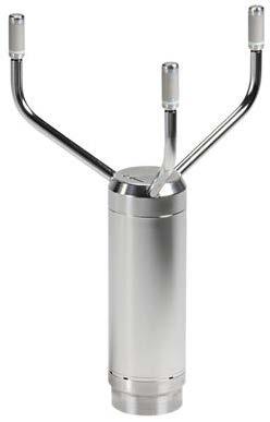


Technical data
Observation range 0 … 360° Starting threshold 0.1 m/s (0.2 mph) Resolution 0.01° Response time 250 ms Accuracy ±2°
Powering specifications
Heating 1) 0 W, 30 W, 150 W, or 250 W Operating temperature 1) −10 … +60 °C (+14 … +140 °F) −40 … +60 °C (−40 … +140 °F) −55 …+70 °C (−67 …+158 °F) Storage temperature −60 … +80 °C (−76 … +176 °F) IP rating IP66 and IP67
Units available m/s, knots, mph, km/h, V, mA, Hz Operating mode Automatic message or poll mode
Mechanical specifications
Compliance marks CE, China RoHS, RCM, UKCA Listing marks SGS (USA and Canada) www.vaisala.com
Messaging specifications Readout update interval 4 Hz (default) and 8 Hz (optional)
Operating environment
Observation range WMT701: 0 … 40 m/s (89 mph) WMT702: 0 … 65 m/s (145 mph) WMT703: 0 … 75 m/s (168 mph) WMT704: 0 … 90 m/s (201 mph)
142
Compliance EU directives and regulations EMC Directive (2014/30/EU) RoHS Directive (2011/65/EU) amended by 2015/863 REACH Regulation (EC 1907/2006)
EMC immunity IEC 61326 1, IEC 60945
Maritime IEC 60945, DNVGL-CG-0339 Electrical safety UL CAN/CSA61010-1C22.2 No. 61010-1-12
Dimensions (H × W × Ø 1)) 348 × 250 × 285 mm (13.70 × 9.84 × 11.22 in) Weight 1.8 kg (4.0 lb) Materials Body and arms, mounting kit Stainless steel AISI 316 Transducers Silicone Connector housing surface Nickel-plated brass 1)Diameter of area covered by transducers. Analog outputs Wind speed Voltage, current, frequency Wind direction Voltage, current, potentiometer
Starting threshold 0.01 m/s (0.0223 mph) Resolution 0.01 m/s (0.0223 mph) Response time 250 ms Accuracy 0 … 75 m/s (168 mph): ±0.1 m/s (0.2 mph) or 2 % of reading, whichever is greater 75 … 90 m/s (201 mph): ±5 % of reading Wind direction measurement performance
Communication interfaces COM1: RS 485 COM2: RS 485, RS 422, RS 232, SDI 12
Communication profiles WMT700, WS425 ASCII, NMEA Standard and Extended (version 0183), SDI-12 (version 1.3), WS425 ASOS, ROSA MES 12, customized Bit rate 300, 1200, 2400, 4800, 9600, 19200, 38400, 57600, or 115200 Available averages Max. 3600 s
Wind speed measurement performance
Operating voltage 9 … 36 V DC (absolute max. 40 V DC) 1) Heating voltage 24 … 36 V DC (absolute max. 40 V DC) 1) Heating power supply requirement 2) Heated transducers Average 32 W Peak 40 W Heated transducers and arms Average 152 W Peak 200 W Heated transducers, arms, and bodyAverage 252 W Peak 350 W at 24 V DC 1)In maritime environments, the normal input voltage ranges are: operating voltage 10 … 30 V DC (−10 … +30 %) and heating voltage 24 … 30 V DC (−10 … +30 %), as defined in the maritime standard IEC 2)The60945.actualpower consumption depends on the temperature.
Virtual temperature Celsius degrees
EMC emissions CISPR 32 / EN 55032, Class B Environmental IEC 60068 2 1, 2, 6/34, 30, 31, 67, 78, IEC VDA60529621415
1)For freezing conditions, select appropriate combination of heating and temperature ranges. Digital outputs
PJB480 Power Junction Box
•Allows
•Robust
•Designed
•IP66
Vaisala Power Junction Box PJB480 provides operational and heating power to Vaisala WINDCAP Ultrasonic Wind Sensor WMT700. PJB480 is designed for demanding conditions, such as maritime use and cold climates. 143
Features •Provides
PJB480 with WMT700 on a pole mast operational and heating power for WMT700 heating WMT700 sensor transducers, arms, and body for demanding conditions, such as maritime use and cold climates waterproof enclosure enclosure of stainless steel
Prevents Build-up of Ice and Snow PJB480 is equipped with two 24 VDC power supplies and has the maximum output power of 480 W. It provides power for keeping the WMT700 sensor operational and heated, thus preventing build-up of ice and snow. With PJB480, WMT700 can be fully heated (including sensor transducers, arms, and body) to keep the sensor functional in the harshest and coldest environments. PJB480 supports one WMT700. Withstands Harsh Weather PJB480 withstands low temperatures, down to −55 °C (−67 °F). Its housing is waterproof (IP66) and made of stainless steel. A mounting plate for wall or bulkhead installation is included in the delivery. PJB480 can also be mounted to a mast using an optional APPK SET mounting kit. Meets Maritime Standards PJB480 is a durable solution for cold climates and demanding maritime conditions; it is compliant with IEC 60945 standards. PJB480 can be used with a standalone WMT700 or with a WMT700 that is part of a Vaisala Automatic Weather Station.
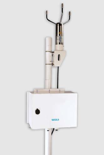
Mechanical Specifications Enclosure dimensions (H × W × D)300 × 400 × 200 mm (11.81 × 15.75 × 7.87 in) Weight 14 kg (30 lb) Materials (enclosure and mounting plate) Stainless steel AISI 316 / EN 1.4404 Coating (enclosure and mounting plate) Painted white, polyester powder coating RAL9003
PJB480 Dimensions, Back View EMC Compliance Immunity EN/IEC 61326 1 (Industrial Environment) / IEC 60945 Insulation IEC 60092 504 Emissions EN55032 / CISPR 32 (Class B) / IEC 60945 www.vaisala.com
Technical Data Operating Environment Operating temperature −55 ... +55 °C (−67 ...+131 °F) 1) Storage temperature −60 ... +70 °C (−76 ...+158 °F) Operating humidity 0 ... 100 %RH, non condensing Maximum operating altitude 2000 m (6 500 ft) 1)Cold start −40 °C (−40 °F) Inputs and Outputs Input voltage 100 ... 240 VAC Input current 10 A Operating frequency 50/60 Hz Output voltage 24 VDC Output current 16 A Maximum output power 480 W Nominal output power 300 W Spare Parts and Accessories Fuse, 2 A, glass tube 5 × 20 mm (0.79 in) 3595 Surge protector 254404SP Mounting kit for pole mast, Ø 60 mm (2.36 in) APPK-SET60 Mounting kit for pole mast, Ø 75 mm (2.95 in) APPK-SET75 Mounting kit for pole mast, Ø 100 mm (3.94 in) APPK-SET100 Mounting kit for pole mast, Ø 106 mm (4.17 in) APPK-SET106 AC (mains) cable To be purchased separately. Min. 3 × 1.5 mm2 (15 AWG)
144
Environmental Compliance Maritime IEC 60945 Electrical safety EN/UL/IEC 61010 1 IP rating IP66 Vibration IEC 60068 2 6/IEC 60945 Dry heat IEC 60068 2 2 Damp heat Cyclic IEC 60068 2 30 Low temperature IEC 60068 2 1 Corrosion and salt mist IEC60068 2 52, VDA 621 415 400 [15.75] 434 [17.09] [11.81]300 mm[in] PJB480 Dimensions, Front View [12.79]325 223 [8.78] 6.5 [0.26] mm [in] 6.5 [0.26] 120 [4.73] 103 [4.06]
WA15 is based on accurate sensors installed on a crossarm. It is designed for demanding wind measurement applications.
Heated bearings withstand cold weather
Sensitive wind vane WAV151 is a counter-balanced, lowthreshold, optoelectronic wind vane. Infrared LEDs and phototransistors are mounted on 6 orbits on each side of a 6bit GRAY-coded disc. Turned by the vane, the disc creates changes in the code received by the phototransistors. The output code resolution is ±2.8°.
•Conicalthresholdanemometer
•Long
•High-performance
With a proven track record of successful installations, Vaisala Wind Set WA15 has earned its reputation as the industry standard in the wind sensor market. WA15 consists of Vaisala Anemometer WAA151, Vaisala Wind Vane WAV151, an optional crossarm, a power supply, and cabling.
WA15 Wind Set Features wind measurement set and successful track record in meteorological applications wind speed and direction measurement measurement starting cups provide excellent linearity shaft prevents bearings from freezing
•Heated
•Accurate
Anemometer with excellent linearity WAA151 is a fast-response, low-threshold anemometer. Three lightweight, conical cups mounted on the cup wheel provide excellent linearity over the entire operating range, up to 75 m/s (168 mph).
A wind-rotated chopper disc attached to the shaft of the cup wheel cuts an infrared light beam 14 times per revolution. This generates a pulse output from the phototransistor. The output pulse rate is directly proportional to wind speed, for example, 246 Hz = 24.6 m/s (55 mph). However, for the highest accuracy, the characteristic transfer function must be used to compensate for starting inertia.
•Low
Heating elements in the shaft tunnels of both the anemometer and vane keep the bearings above freezing temperatures in cold climates. Complete package available The anemometer and vane are designed to be mounted on Vaisala crossarms. 145
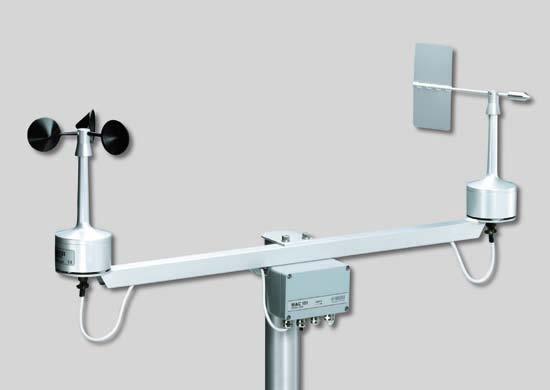
Materials Housing AlMgSi, gray anodized Cup PA, reinforced with carbon fiber
Swept radius of vane 172 mm (6.77 in) Weight 660 g (1.46 lb)
Mounting to a pole mast with a nominal outside diameter 60 mm (2.36 in)
Sensor/Transducer type Optical code disc Observation range at wind speed 0.4 … 75 m/s (0.9 … 168 mph) 0 … 360° Starting threshold < 0.4 m/s (0.9 mph)
WAV151 inputs and outputs
Materials Housing AlMgSi, gray anodized Vane AISI 12, anodized WA15 mechanical specifications
Transducer output level (Iout < +5 mA) High state > Uin –1.5 V (Iout > -5 mA) Low state < 2.0 V Accuracy within 0.4 … 60 m/s (0.9 … 134 mph) With characteristic transfer function (standard deviation) ±0.17 m/s (0.38 mph) With simple transfer function Uf = 0.1 × R ±0.5 m/s (1.12 mph) 2) 1)Measured with the cup wheel in position least favored by flow direction. The optimum position yields a < 0.35 m/s (0.8 mph) starting threshold. 2)Typical error vs. speed with the simple transfer function used.
WAV151 measurement performance
Transducer output 0 … 75 m/s (0 … 168 mph) 0 … 750 Hz square wave Characteristic transfer functionUf (wind speed) = 0.328 + 0.101 × R (output pulse rate)
Operating temperature 1) −50 … +55 °C (−58 … +131 °F) Storage temperature −60 … +70 °C (−76 … +158 °F) Operating humidity 0 … 100 %RH IP rating IP65 1)With shaft heating. WAA151 mechanical specifications Dimensions (H × Ø) 240 × 90 mm (9.45 × 3.54 in) Swept radius of cup wheel 91 mm (3.58 in) Weight 570 g (1.26 lb)
Resolution ±2.8° Damping ratio 0.19 Overshoot ratio 0.55 Delay distance 0.4 m (1 ft 4 in) Accuracy Better than ±3° Output 6 bit parallel GRAY code Transducer output level (Iout < +5 mA) High state > Uin –1.5 V (Iout > -5 mA) Low state < 1.5 V
Operating power supply Uin = 9.5 … 15.5 V DC, 20 mA typical Heating power supply 20 V AC or DC, 500 mA nominal Settling time after power turn-on< 100 µs
Operating temperature 1) −50 … +55 °C (−58 … +131 °F) Storage temperature −60 … +70 °C (−76 … +158 °F) Operating humidity 0 … 100 %RH IP rating IP65 1)With shaft heating.
WAV151 mechanical specifications
Dimensions (H × Ø) 300 × 90 mm (11.81 × 3.54 in)
Technical Data
WAA151 measurement performance
WAA151 inputs and outputs
Electrical connections MIL C 26482 type, 6 wire cable Cabling 6 wire cable through cross arm Recommended connector at cable endSouriau UTS6JC10E6P Operating power supply Uin = 9.5 … 15.5 V DC, 20 mA, typical Heating power supply AC or DC 20 V, 500 mA, nominal Settling time after power-up < 30 µs WAA151 operating environment
WAV151 operating environment
Crossarm length 800 mm (31.50 in)
Electrical connections MIL C 26482 type, 10 wire cable Cabling 10 wire cable through cross arm Recommended connector at cable endSouriau UTS6JC12E10P
WA15 compliance Compliance marks CE 146
Sensor/Transducer type Cup anemometer/opto-chopper Observation range 0.4 … 75 m/s (0.9 … 168 mph) Starting threshold 1) < 0.5 m/s (1.1 mph) Distance constant 2.0 m (6 ft 7 in)
Junction box 125 × 80 × 57 mm (4.92 × 3.15 × 2.24 in)
147
Crossarm and serial RS-485 transmitter WAC155 Component board for WAC155 WAC155CB Crossarm and termination box WAC151 16-lead signal cable 10 m for WA15/25, open leads on both ends ZZ45048 6-lead heating power cable 10 m for WA15/25, open leads on both ends ZZ45049 Special length 16-lead signal cable for WA15/25, open leads on both ends ZZ45048SPEC Special length 6-lead heating power cable for WA15/25, open leads on both ends ZZ45049SPEC Sensor cable for WAA151/252 0.8 m (31.5 in) , open lead on one end (6 wires), connector 230118 on another end ZZ45036 Sensor cable for WAV151/252 0.8 m (31.5 in), open lead on one end (10 wires), connector 230119 on another end ZZ45037 Special length sensor cable for WAA151/252, open lead in one end (6 wires), connector 230118 on another end ZZ45036SPEC Special length sensor cable for WAV151/252, open lead in one end (10 wires), connector 230119 on another end ZZ45037SPEC Connector WAA151, WAA252 230118 Connector WAV151, WAV252 230119
WA15 spare parts and accessories Service kit for one WA15/25 sensor (a set of bearings and gasket) 16644WA Cup assembly WAA151 7150WA Tail assembly WAV151 6389WA Sensor board WAA151 1433WA Sensor board WAV151 1434WA Attachment hardware for WAA151/252 and WAV151/252 16546WA
Crossarm and analog transmitter WAT12 Component board for WAT12 16637WA Power supply for WA15 WHP151 Power board for WHP151 power supply WA35120 www.vaisala.com
Vaisala Wind Set WA25 is a high-quality cup and vane wind measurement station designed for arctic conditions. WA25 consists of Vaisala Anemometer WAA252, Vaisala Wind Vane WAV252, an optional crossarm, a power supply, and cabling.
Sensitive Wind Vane WAV252 is a counterbalanced, lowthreshold, optoelectronic wind vane providing a 6-bit GRAY-coded message. Turned by the vane, the disc creates changes in the code received by the phototransistors. The code is changed in steps of 5.6°.
Features
•Conicalthresholdanemometer cups provide excellent linearity
Most of the heating power is consumed where it is needed most – in the cups and vane. Foil heaters, integrated into the cups and vane, prevent snow buildup and ice formation.
•Accurate wind speed and direction measurement
Heating Provides Resistance to Snow and Ice
•Cups and vane, sensor bodies and bearings are heated to prevent snow build-up and ice formation
Heating power is also supplied to the sensor shafts, bearings, and bodies. This keeps the sensor bodies free of ice, which is important for maintaining the aerodynamic performance.
Anemometer with Excellent Linearity WAA252 is a fast-response, lowthreshold anemometer. Three lightweight, conical cups mounted on the cup wheel provide excellent linearity over the entire operating range, up to 75 m/s (168 mph). A wind-rotated chopper disc attached to the shaft of the cup wheel cuts an infrared light beam 14 times per revolution. This generates a pulse output from a phototransistor. The output pulse rate is directly proportional to wind speed (for example, 246 Hz = 24.6 m/s). However, for the highest accuracy, the characteristic transfer function must be used to compensate for starting inertia.
•Non-freezing, high-performance wind set
Complete Package Available The anemometer and vane are designed to be mounted on Vaisala crossarms. 148
•Low measurement starting
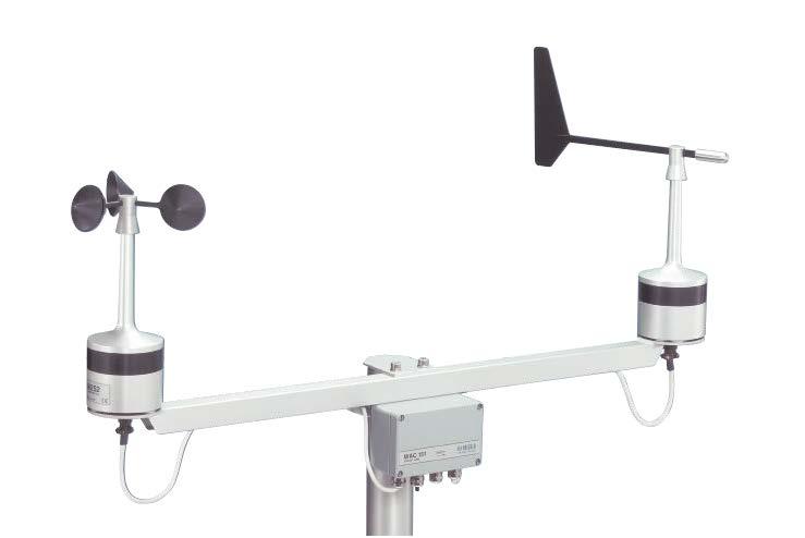
Technical Data
Operating power supply Uin = 24 VDC ± 10%, max. 3.2 A
Measurement range 0 … 360°
Characteristic transfer functionUf (wind speed) = 0.328 + 0.101 × R (output pulse rate) Transducer Output Level (Iout < +5 mA) High state > 11 V (Iout > -5 mA) Low state < 1.5 V Accuracy Within 0.4 … 60 m/s (0.9 … 134 mph) With characteristic transfer function (standard deviation) ±0.17 m/s (0.38 mph) With simple transfer function Uf = 0.1 × R ±0.5 m/s (1.12 mph)2)
Exploratory vibration test MIL-STD-167-1 Humidity test MIL-STD-810E, Method 507.3 Salt fog test MIL-STD-810E, Method 509.3 EMC compliance EN/IEC 61326-1:1997 + Am1:1998; Generic Environment WAV252 Mechanical Specifications
Operating temperature 55 … +55 °C (-67 … +131 °F) Storage temperature 60 … +70 °C (-76 … +158 °F) Wind tunnel tests ASTM standard method D5366-93
Starting threshold < 0.4 m/s (0.9 mph) Resolution ±2.8° Damping ratio 0.3 Overshoot ratio 0.4 Delay distance < 0.5 m (1 ft 8 in) Accuracy Better than ±3° Output 6-bit parallel GRAY code Transducer Output Level (Iout < +3 mA) High state > 11 V (Iout > -3 mA) Low state < 1.5 V WAV252 Operating Environment
Typical Power Consumption (Uin = 24 VDC) Below +2 °C (+36 °F) (heating on) 50 W Above +6 °C (+43 °F) (heating off) 1 W Output code 6-bit parallel GRAY Recommended connector at cable endSOURIAU MS3116F12-10P Plug 6-PIN MIL-C-26482 type 149
Materials Housing: AlMgSi, gray and black Vane:anodizedCarbon fiber and glass fiber
WAA252 Operating Environment Operating temperature 55 … +55 °C (-67 … +131 °F) Storage temperature 60 … +70 °C (-76 … +158 °F) Wind tunnel tests ASTM standard method D5366-90 Exploratory vibration test MIL-STD-167-1 Humidity test MIL-STD-810E, Method 507.3 Salt fog test MIL-STD-810E, Method 509.3 EMC compliance EN/IEC 61326-1:1997 + Am1:1998; Generic Environment
Recommended connector at cable endSOURIAU MS3116F10 6P Plug 6-PIN MIL-C-26482 type
Typical Power Consumption (Uin = 24 VDC) Below +2 °C (+36 °F) (heating on) 72 W Above +6 °C (+43 °F) (heating off) 1 W Output 0 ... 750 Hz square wave
IP rating IP65 Dimensions (H × Ø) 264 × 90 mm (10.39 × 3.54 in) Swept radius of cup wheel 91 mm (3.58 in) Weight 0.8 kg (1.76 lb) Materials Housing: AlMgSi, gray and black Cup:anodizedPC,reinforced with glass fiber
IP rating IP65 Dimensions (H × Ø) 355 × 90 mm (13.98 × 3.54 in) Swept radius of vane 218 mm (8.58 in) Weight 0.85 kg (1.87 lb)
WAA252 Measurement Performance
WAA252 Mechanical Specifications
1)Measured with cup wheel in position least favoured by flow direction. Optimum position gives approx. 0 35 m/s (0.78 mph) threshold. 2)Typical error vs. speed with the simple transfer function used.
Operating power supply Uin = 24 VDC ± 10%, max. 3.2 A
WAV252 Inputs and Outputs
Measurement range 0.4 ... 75 m/s (0.9 ... 168 mph) Starting threshold < 0.5 m/s (1.1 mph) 1) Distance constant 2.7 m (8 ft 10 in)
WAA252 Inputs and Outputs
WAV252 Measurement Performance
150
WA25 Spare Parts and Accessories Service kit for one WA15/25 sensor (set of bearings and gasket) 16644WA Crossarm and serial RS-485 transmitter WAC155 Component board for WAC155WAC155CB Heated cup assembly WAA252WA35066 Heated tail assembly WAV252WA35336
Connector WAA151, WAA252 230118 Connector WAV151, WAV252 230119 Crossarm and termination boxWAC151 16-lead signal cable (10 m) for WA15/25, open leads on both ends ZZ45048 6-lead heating power cable (10 m) for WA15/25, open leads on both ends ZZ45049 Special length 16-lead signal cable for WA15/25, open leads on both ends ZZ45048SPEC Special length 6-lead heating power cable for WA15/25, open leads on both ends ZZ45049SPEC Sensor cable for WAA151/252 0.8 m (31.5 in), open lead on one end (6 wires), connector 230118 on other end ZZ45036 Sensor cable for WAV151/252 0.8 m (31.5 in), open lead on one end (10 wires), connector 230119 on other end ZZ45037 Special length sensor cable for WAA151/252, open lead on one end (6 wires), connector 230118 on other end ZZ45036SPEC Special length sensor cable for WAV151/252, open lead in one side (10 wires) and connector 230119 in another side ZZ45037SPEC Crossarm and analog transmitterWAT12 Component board for WAT12 16637WA Attachment hardware for WAA151/252 and WAV151/252 16546WA Power supply for WA25 WHP25 Power board for WHP25 power supplyWA35078 www.vaisala.com
WAC155 Serial Wind Transmitter
Vaisala Serial Wind Transmitter WAC155 converts the digital data supplied by Vaisala WA15 and WA25 series wind sensors into standard data messages for use in the RS-485 bus. WAC155 consists of a component board in a junction box and a crossarm for mounting the wind WAC155sensors. communicates with the host system over 2-wire RS-485 line. The standard sensor connections are for WA15 or WA25 series anemometers and wind vanes.
A 20 … 30 V supply is recommended for remote power. This is to minimize the current and the voltage drop in the cable. The allowable transmitter distance depends on the wire gauge of the cable, and is typically several hundreds of meters. It should be noted that the peak operating current can reach 30 mA even in power-save mode.
Features
•Sensor heating control with adjustable temperature limits
The total average current consumed in power-save mode is less than 10 mA. This, along with the good line transient protection, allows for remote supply of the operating power.
•Auto-detection of sensor failure and system error
Optional Heating Power WAC155 also provides the sensors for throughput and control of heating power.
151
•Marine use can be enabled, with over 500 VAC isolation from system to frame
Long Distance Operation Only a 4-wire cable is required for the line between WAC155 and the host. One wire pair provides the operating power. The other pair is for the serial line. For long distances, the RS-485 line terminator can be activated with the onboard jumper plug. WAC155 accepts 9 … 31.5 VDC as input power, from which it also generates operating power for the sensors.
•Superior protection against lightning surges allows for installation to high towers
Flexible Communications Wind data is provided in standard NMEA messages. In addition, a service connection is available for configuration and status information. In the same RS-485 bus, there may be one or more transmitters. When WAC155 is alone in the bus, it can work in autotransmit mode, sending data in preconfigured intervals. When more devices are involved, the host must control the data transit by polling one device at a time with an NMEA query. Each transmitter has a configurable ID for device addressing.
•Measures the wind data at configurable interval and computes wind average values over adjustable period
Self-Diagnostics
When the service connection is open or the system has been started recently, the onboard indicator LED flashes red when any error condition is active.
During an error condition NMEA messages also carry a flag for invalid data. The error flag can result from an incorrect system voltage level, absence or failure of a wind sensor, or system memory error. The cause of error is shown in a special error message.
•Averagesystems power need 0.2 W, including the sensors
WAC155 converts the wind speed and direction data for use in the RS-485 bus.
•Communicates over 2-wire RS-485 line with NMEA 0183 protocol (MWV, MWV query)
•Input voltage range of 9 … 31.5 V enables use in both 12 V and 24 V
The heating power connection, if required, calls for an extra pair of wires. Since a sensor typically requires 0.5 A current for heating, the power is most conveniently supplied from a local power source. By default WAC155 switches heating on in temperatures below +4 °C (+39 °F) (user-adjustable).
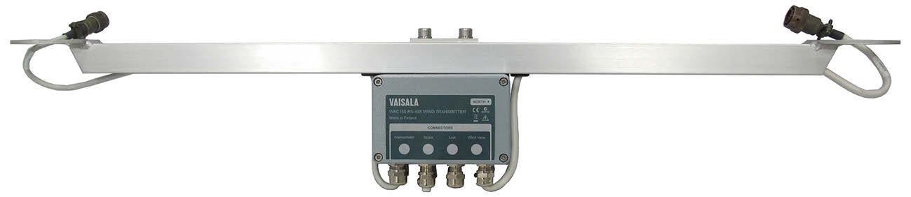
Averaging interval 3 s (selectable range 0.25 … 5 s)
www.vaisala.com 152
WAC155
Technical Data
Input operating voltage 9 … 31.5 V Input operating current (incl. both sensors) Power-save enabled: 7 mA typically at 24 PowerV save disabled: 37 mA typically at 24 V Heating control, WA15 On at 3 °C (37 °F) / Off at 5 °C (41 °F), adjustable Input heating voltage, WA15 16 … 24 V DC or V AC rms with 1 or 2 sensors in parallel 32 … 48 V DC or 32 … 43 V AC rms with 2 sensors in series Input heating current 1.0 A typically at 20 V with 1 or 2 sensors in parallel 0.5 A typically at 40 V with 2 sensors in series Heating for WA25 Passed by with expansion connector Signal input 6 bit parallel GRAY code (0.5/10.5 V typical) from wind vane 0 … 750 Hz square wave (0.5/10.5 V typical) from anemometer Data output 2 wire half-duplex RS 485, 9600 8N1 1) Service interface RS 232 or RS 485 Message protocol NMEA 0183, MWV, and MWV Query
Updating interval 0.25 s Wind speed Observation range 0 … 75 m/s (0 … 168 mph) Observation frequency 4 Hz Resolution 0.1 m/s Wind direction Observation range 0 … 360° Observation frequency 32 Hz Resolution 1) 2.0°
WAC155 spare parts
Spare part Order code Component board for WAC155 WAC155CB Crossarm and serial RS-485 transmitter WAC155 Sensor cable for WAA151/252 0.8 m (31.5 in), open lead on one end (6 wires), connector 230118 on other end ZZ45036 Sensor cable for WAV151/252 0.8 m (31.5 in), open lead on one end (10 wires), connector 230119 on other end ZZ45037
WAC155 operating environment Operating temperature −55 … +60 °C (−67 … +140 °F) Storage temperature −60 … +70 °C (−76 … +158 °F) Operating humidity 0 … 100 %RH IP rating IP65
1)Adjustable rate: 300 … 19200, 7/8, O/E/N, 1/2.
Weight 1.5 kg (3.3 lb) Material Aluminum Mounting To Ø 60 mm (2.36 in) pole mast Dimensions Crossarm and junction box (W × H × D)887 × 165 × 157 mm (34.92 × 6.50 × 6.18 in) Junction box (W × H × D) Without cable glands: 127 × 82 × 58 mm (5.00 × 3.23 × 2.28 in) With cable glands: 127 × 110 × 58 mm (5.00 × 4.33 × 2.28 in)
WAC155 measurement performance
inputs and outputs
Special length sensor cable for WAV151/252, open lead in one side (10 wires) and connector 230119 in another side ZZ45037SPEC Connector WAA151, WAA252 230118 Connector WAV151, WAV252 230119
WAC155 mechanical specifications
Special length sensor cable for WAA151/252, open lead on one end (6 wires), connector 230118 on other end ZZ45036SPEC
1)Gained by averaging the eight samples in each 0.25 second period.
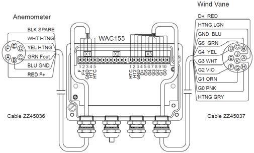
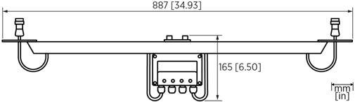
WAT12 Analog Wind Transmitter Features
•Converts the digital data supplied by Vaisala Wind Set WA15 and Vaisala Wind Set WA25 into two industry standard analog current loops: one for speed, the other for
Vaisala Analog Wind Transmitter WAT12 is an economic solution to a standard interface between Vaisala wind sensors and analog panel meters, chart recorders, digital LCD or LED displays, data loggers, computers with analog inputs, or other instruments with an analog input interface. The transmitter converts the wind speed and direction data measured by either Vaisala Wind Set WA15 or Vaisala Wind Set WA25 into two analog current loop signals, respectively. The power to the sensors is also supplied through the WAT12 unit. WAT12 consists of a PC board unit in a junction box and a cross arm for mounting the wind sensors. A 4-wire cable for the wind speed and direction signals and power supply is needed between the transmitter and the receiving end. User-selectable Loop Current Several loop current ranges are available, such as 4 … 20 mA, 0 … 10 mA, and 1 … 5 mA. The loops are supplied by highside drivers with a return to the signal and power ground. Nearly any input type can be driven. The transmitter accepts a wide range of input power, from 12 to 28 VDC. With 5 mA loop current selected, the total current consumed is less than 40 mA (including the sensors and the loop current). This makes it possible to remotely supply the operating power from a distance of several kilometers, even through private or leased telephone lines.
Optional Heating Power
•Selectabledirection loop current
•Wide
WAT12 is designed to convert the wind speed and direction data measured by WA15 or WA25 into two analog current loop signals.
•Provides the sensors with a throughput for optional heating power
WAT12 also provides the sensors for throughput of optional heating power. The heating power connection, if required, needs an extra pair of wires. Since the heating elements typically consume about 500 mA, the heating power is most conveniently supplied from a local power source. An optional thermostat switch is available for automatic connection of heating power in temperatures below +4 °C (+39.2 °F).
153
•Suitable for nearly any input type range of input power
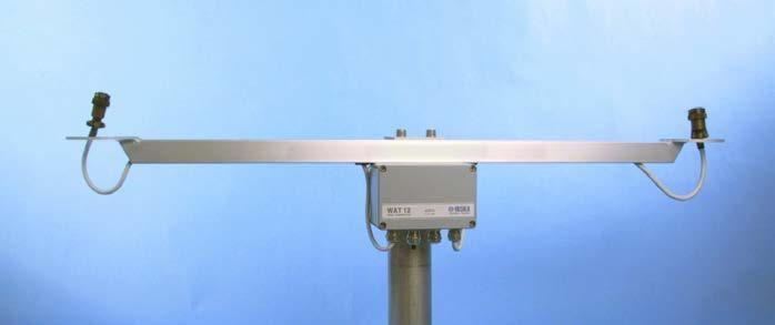
Inputs and outputs Input operating power 12 ... 28 VDC, 30 mA Output sensor power On-board regulated to 10.7 VDC typically Signal input from sensors Wind direction 6-bit parallel GRAY code (optionally 7 bits) Wind speed Pulse frequency 0 ... 750 Hz Output signals
Full-scale options (jumper selectable)For direction: 0 ... 360° / 0 ... 540° For speed: 0 ... 51.2 m/s (0 ... 115 mph) / 0 ... 76.8 m/s (0 ... 172 mph) Signal cable Min. 4 wires (Vin+, Vin–, DOP, SOP)
EMC compliance EN 61326-1, Basic electromagnetic environment Mounting To Ø 60 mm (2.36 in) pole mast Weight 1.5 kg (3.31 lb) Dimensions PC board 114 × 69 mm (4.49 × 2.72 mm) Junction box (H × W × D) 80 × 125 × 57 mm (3.15× 4.92 × 2.24 in) Cross arm length 800 mm (31.50 in) Materials Cross arm Anodized aluminum Junction box Aluminum, painted grey 887[34.92] [6.50]651
5 mA loop: 1800 Ω 10 mA loop: 900 Ω 20 mA loop: 450 Ω
154
Operating humidity 0 ... 100 %RH
2 analog current loops 1 for direction, 1 for speed Highside drivers; the loops return to the common signal and power ground
Mechanical specifications
ANEMOMETER WINDVANE Dimensions in mm (inches) www.vaisala.com
Technical Data
Operating environment Operating temperature –55 ... +55 °C (-67 ... +131 °F) Storage temperature –60 ... +70 °C (-76 ... +158 °F)
Typical loop driving voltage 10 V Output accuracy > 1 % of full scale Loop current options (jumper selectable) 0 ... 5 mA 1 ... 5 mA 0 ... 10 mA 2 ... 10 mA 0 ... 20 mA 4 ... 20 mA Max. loop resistance (including cable resistance and receiver's input resistance)
•Combined
•Choice
•Low
Vaisala Wind Sensor WM30 is a compact and economical wind speed and direction sensor. The rotating cup anemometer at the top of the unit provides a linear response to wind speed. The vane, which is attached to the body of the unit, provides a fast response to wind direction.
The shape, dimensions, and material of the cups contribute to accurate measurement. The cups are carefully tested to give linear response between the wind speed and the angular velocity of the cup wheel. The wind vane is located directly beneath the cup assembly and is made of a durable, lightweight material that ensures fast response and low inertia. Flexible outputs A relay contact output is provided for wind speed. The wind speed can be recorded either by counting the number of pulses within a fixed time period, or by measuring the time between successive Apulses.potentiometer detects the position of the vane. The potentiometer features low starting and running torque, linear resistance, and a long operation life. It has a single wiper with an open gap of less than 5 degrees. With constant voltage supplied to the potentiometer, the output voltage is directly proportional to the azimuth angle.
The cups and vane are made of reinforced polyamide (PA) plastic which guarantees a rigid structure even at the highest wind speeds. The electronics are located inside an anodized aluminum core which creates not only a firm body, but a watertight enclosure for the electronics as well. This provides full protection against water, dust, pollutants, and electromagnetic interference.
Easy installation A mast adapter for a 30 mm tube is supplied with the sensor. An installation kit for larger tube diameters, from 50 to 110 mm, is available as an option.
Optimal for applicationslow-power
155
Built for harsh conditions
Vaisala Wind Sensor WM30 provides accurate wind measurement in a compact and economical package.
•Compactprice
Accurate wind measurement
The electronics are designed specifically for applications where low power consumption is essential.
WM30 Wind Sensor Features wind speed and direction sensor with affordable and light design is optimal for mobile applications power consumption •Fast and linear response to wind of one-wiper or two-wiper potentiometer models
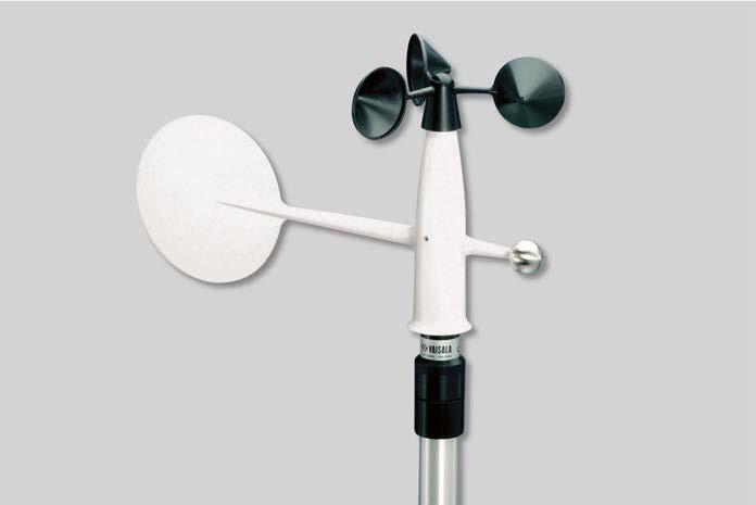
Technical data Measurement performance
Inputs and outputs Supply voltage 3 … 15 VDC Connector 5-pin male with 12 mm threads Recommended connector at cable endBINDER 99 1436 814 05
Operating temperature -40 … +55 °C (-40 … +131 °F) Storage temperature -60 … +65 °C (-76 … +149 °F)
Operating environment
Wind speed Measurement range 0.5 … 60 m/s (1.1 … 134 mph) Starting threshold < 0.4 m/s (0.9 mph)
Mechanical specifications
EMC compliance EN 61326-1, Basic electromagnetic environment www.vaisala.com 156
Dimensions (H × Ø) 265 × 360 mm (10.43 × 14.17 in) Weight 360 g (12.70 oz)
Materials Housing AlMgSi, gray anodized Cups PA, reinforced with carbon fibre, black Vane PA, reinforced with fiberglass, white Spare parts and accessories
Mounting adapter WMS30KIT Sensor connector 19370 Sensor connector and cable, 10 m (32 ft 10 in) 19904 Compliance Wind tunnel tests ASTM standard method D5366-93 ASTM standard method D5096-90
Distance constant 2 m (6 ft 7 in) Transducer output 1 Hz at approximately 0.7 m/s (1.6 mph)
Accuracy Better than ±3° 1)U = wind speed [m/s], F = output frequency [Hz]
Characteristic transfer function U = -0.24 + 0.699 × F 1) Accuracy (within range 0.4 … 60 m/s (0.9 … 134 mph)): Wind speed < 10 m/s (22 mph): ±0.3 m/s Wind speed > 10 m/s (22 mph): ±2 % Wind direction Measurement range WMS301 with 1-wiper potentiometer: 0 … WMS302355° with 2-wiper potentiometer: 0 … 360° Starting threshold < 1.0 m/s (2.2 mph) Damping ratio 0.3 Overshoot ratio 0.4 Delay distance 0.6 m (1 ft 12 in)
Vaisala Surge Protector WSP150 is a compact transient overvoltage suppressor designed for outdoor use. It can provide overvoltage protection for 2 power supply lines and RS-422, RS-485, RS-232 serial communication, or 2 mA loop lines.
WSP150 also provides an additional filter for blocking the HF-conducted interference. Applications Vaisala recommends using WSP150 when wind and weather instruments are installed on top of high buildings or masts and in open grounds, that is, anywhere with an elevated risk of lightning. 157
WSP150 offers 3-stage protection against surge currents up to 10 kA entering through the power and signal cables. Powerful technology WSP150 has 4 channels, 2 of which are dedicated to power lines and 2 for data lines. Each channel uses a 3-stage protection scheme: first there are discharge tubes, then voltage dependent resistors (VDR), and finally transient zener diodes. Between each stage, there are either series inductors or resistors.
WSP150 Surge Protector Features •Superior 3-stage, transient surge •Toleratesprotectionup to 10 kA surge •Providescurrents additional filtering for blocking the HF-conducted •Robustinterferencestructure, IP66 housing •Both differential and common mode protection on each channel •2 power and 2 data channels •Can be used for example with WXT530, WA15, WMT700 (nonheated), WM30, DSC211, and •Applications:DST111 mast installations of weather measurement networks, meteorological stations in wind parks
Both differential and common mode protection is provided for each channel: across the wire pairs, against the operating voltage ground, and against the earth.
Vaisala Surge Protector WSP150 is a compact transient overvoltage suppressor designed for outdoor use. It can provide overvoltage protection for 2 power supply lines and RS-422, RS-485, RS-232 serial communication or 2 mA loop lines. It can be used with WXT530 series, WMT700 (non-heated) WA15 wind set, WM30 wind set, DSC211, and DST111. Also other instruments can be protected if the current consumption is less than 1.5 A. Superior protection A lightning strike nearby may induce a high voltage surge, which the integral transient suppressor of the instrument may not tolerate. Additional protection is needed, especially where frequent and severe thunderstorms are common and where cables longer than 30 m (98 ft 5 in) are used. Also use WSP150 if you have unshielded, open-wire lines.
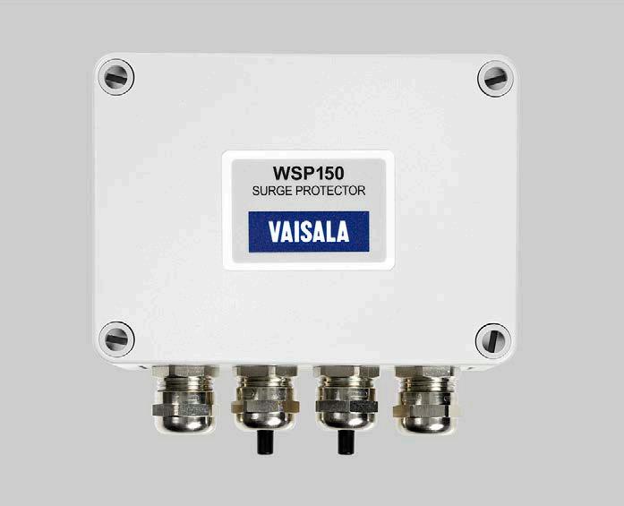
Operating temperature -52 … +70 °C (-60 … +158 °F) Storage temperature -52 … +70 °C (-60 … +158 °F) Installation temperature -40 … +70 °C (-40 … +158 °F)
Input voltage 1) Power channels: max. ±43 V Data channels: max. ±13 V
Housing material Polycarbonate, stainless steel Housing dimensions (H × W × D)94 × 130 × 58 mm (3.70 × 5.12 × 2.28 in) Dimensions with cable glands and mounting assembly (H × W × D) 112 × 130 × 69 mm (4.41 × 5.12 × 2.72 in) Cables (Ø) 5 … 10 mm (0.20 … 0.39 in) Wires (Ø) 0.4 … 1.7 mm (0.016 … 0.067 in) (AWG 26 … 14) Compliance EMC surge tolerance EN 61000-4-5 (4 kV, 2 kA) IEEE C62.45 (6 kV, 3 kA) IP rating IP66 (NEMA 4X) WSP150 dimensions in mm [in] www.vaisala.com 158
Inputs and outputs
Operating environment
Maintenance work temperature-40 … +70 °C (-40 … +158 °F)
WSP150 technical data
Turn-on voltage Power channels: max. ±60 V Data channels: max. ±16 V Surge current To earth: max. 10 kA Differential: max. 5 kA 1)Across channel line pair and from line to GND, terminals #3
Mechanical specifications Weight 0.65 kg (1.43 lb)
Input common mode voltage Any line to earth: max. ±72 V Throughput current Power lines: max. 1.5 A Data lines: max. 0.16 A Throughput resistance (per line)Power lines: max. 0.3 Ω Data lines: max. 15 Ω
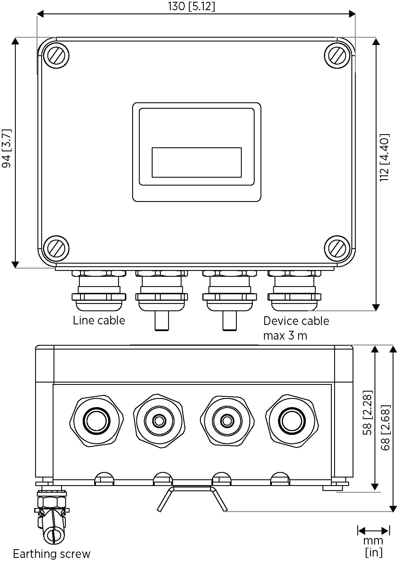
WSP152 has 4 channels, 2 dedicated to power lines and 2 for data lines. Each channel uses a three-stage protection scheme: first there are discharge tubes, then voltage dependent resistors (VDR), and finally transient zener diodes. Between each stage, there are either series inductors or resistors.
Vaisala Surge Protector WSP152 is a compact transient overvoltage suppressor designed for the protection of the USB connection of a computer connected to Vaisala WXT530. Excellent protection WSP152 is designed to protect the host PC against surges entering through the USB port. For example, a nearby lightning strike may induce a highvoltage surge, which is not tolerated by the protection of the USB cable or the port itself. Therefore, additional protection is needed, especially where frequent and severe thunderstorms are common and where cables longer than 30 m (98 ft 5 in) are used. Note that the USB connection of a PC is for indoor use only.
Both differential and common mode protection is provided for each channel: across the wire pairs, against the operating voltage ground, and against WSP152earth.alsoincludes noise filtering against HF and RF interference. Applications Vaisala recommends using WSP152 when USB cables are used for permanent connections. The surge protector is always recommended when there is an elevated risk of a lightning strike. 159
WSP152 offers three-stage protection against surge currents of up to 10 kA that may enter through the USB cable or the port. How does WSP152 work?
WSP152 Surge Protector Features •Excellent three-stage, transient surge •Toleratprotectionesupto10 kA surge •Providescurrrentsadditional filtering for blocking the HF-conducted •Bothinterferencedifferential and common mode protection on each channel •2 power and 2 data channels •Protects the USB connection of a PC connected to Vaisala Weather Transmitter WXT530 Series
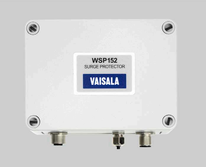
www.vaisala.com 160
Input common mode voltage Any line to earth: max. ±72 V Throughput current Power lines: max. 1.5 A Data lines: max. 0.16 A Throughput resistance (per line)Power lines: max. 0.3 Ω Data lines: max. 15 Ω
Dimensions with cable glands and mounting assembly (H × W × D) 112 × 130 × 69 mm (4.41 × 5.12 × 2.72 in)
Compliance EMC surge tolerance EN 61000-4-5 (4 kV, 2 kA) IEEE C62.45 (6 kV, 3 kA) IP rating IP66 (NEMA 4X)
WSP152 technical data
Turn-on voltage Power channels: max. ±60 V Data channels: max. ±16 V Surge current To earth: max. 10 kA Differential: max. 5 kA Mechanical specifications Weight 0.65 kg (1.43 lb) Housing material Polycarbonate, stainless steel Housing dimensions (H × W × D)94 × 130 × 58 mm (3.70 × 5.12 × 2.28 in)
Operating temperature -52 … +70 °C (-60 … +158 °F) Storage temperature -52 … +70 °C (-60 … +158 °F) Installation temperature -40 … +70 °C (-40 … +158 °F)
Maintenance work temperature-40 … +70 °C (-40 … +158 °F)
Inputs and outputs
Operating environment
Input voltage 1) Power channels: max. ±43 V Data channels: max. ±13 V
Cables (Ø) 4 … 8 mm (0.16 … 0.31 in) Wires (Ø) 0.4 … 1.7 mm (0.016 … 0.067 in) (AWG 26 … 14)
Accessories Description Order code WXT530 cable 10 m, connectors on both ends 215952 Vaisala USB cable 1.4 m 220782 WSP152 dimensions in mm [in]
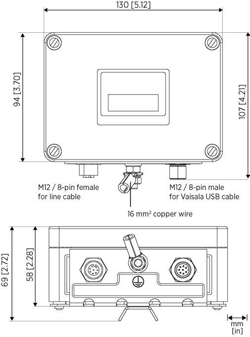
Long-term stability
Fast measurements
Vaisala HUMICAPâ Humidity and Temperature Probe HMP155 provides reliable humidity and temperature measurement. It is designed especially for demanding outdoor applications. 161
With its fast response time, the additional temperature probe for HMP155 is ideal for measuring in environments with changing temperatures. The membrane filter speeds up the relative humidity measurement. Long lifetime Protecting the sensor from precipitation, and scattered and direct solar radiation increases its lifetime. Thus, Vaisala recommends installing HMP155 in one of the following radiation shields: DTR503, DTR13, or Stevenson screen. For the additional temperature probe, an installation kit is available for Vaisala DTR502 Radiation Shield. Calibration The probe can be calibrated using a computer with a USB cable, with the push buttons, or with the MI70 indicator.
HMP155 HUMICAP Humidity and Temperature Probe HMP155 with an additional temperature probe and optional Stevenson screen installation kit. Features •Vaisala HUMICAPâ180R sensor: superior long-term stability •Optional warmed humidity probe and chemical purge • •USBPlug-and-playconnection for service use •Use with DTR13 and DTR503 radiation shields and a Stevenson •Weather-proofscreen housing IP66 •Optional, fast temperature probe • Different output possibilities: voltage, RS-485, resistive Pt100 •Applications: meteorology, aviation and road weather, instrumentation
HMP155 uses the proven Vaisala HUMICAPâ180R sensor that has excellent stability and withstands well harsh environments. The probe structure is solid and the sensor is protected by default with a sintered teflon filter, which gives maximum protection against water, dust, and dirt. Warmed probe and highhumidity environment Measuring humidity reliably is challenging in environments where humidity is near saturation. Measurements may be corrupted by fog, mist, rain, and heavy dew. A wet probe may not give an accurate measurement in the ambient air. This is an environment to which Vaisala has designed this patented, warmed probe for reliable measurements. As the sensor head is warmed continuously, the humidity level inside it stays below the ambient level. Thus, it also reduces the risk of condensation forming on the probe.
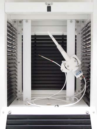
At −60 … −40 °C (−76 … −40 °F)±(1.4 + 0.032 × reading) %RH
Temperature measurement performance Sensor Pt100 RTD element, Class F 0.1 IEC 60751 Observation range −80 … +60 °C (−112 … +140 °F) Response time for additional temperature probe in 3 m/s (7 mph) air flow 63 %: < 20 s 90 %: < 35 s Other measured variables Dew point / frost point temperature, wet bulb temperature, mixing ratio
Sensor HUMICAPâR2, 180R and INTERCAP for typical applications HUMICAPâR2C, 180RC and INTERCAPC for applications with chemical purge and/or warmed probe
Accuracy (including non-linearity, hysteresis, and repeatability)
1) Defined as ±2 standard deviation limits. Small variations possible (see also the calibration certificate).
At +15 … +25 °C (+59 … +77 °F)±1 %RH (0 … 90 %RH) ±1.7 %RH (90 … 100 %RH)
Observation range 0 … 100 %RH Response time at +20 °C (+68 °F) in still air with sintered Teflon filter 63 %: 20 s 90 %: 60 s Factory calibration uncertainty at +20 °C (+68 °F)1) ±0.6 %RH (0 … 40 %RH) ±1.0 %RH (40 … 95 %RH)
Operating temperature for humidity measurement −80 … +60 °C (−112 … +140 °F)
Storage temperature −80 … +60 °C (−112 … +140 °F)
At −40 … −20 °C (−40 … −4 °F)±(1.2 + 0.012 × reading) %RH
At +40 … +60 °C (+104 … +140 °F)±(1.2 + 0.012 × reading) %RH
Operating humidity 0 … 100 %RH IP rating IP66 Inputs and outputs Operating voltage 7 … 28 V DC Minimum operating voltage 0 … 1 V output or RS 485: 7 V 0 … 5 V output, or warmed probe: 12 V 0 … 10 V output, chemical purge, or XHEAT: 16 V Outputs Voltage output: 0 … 1 V, 0 … 5 V, 0 … 10 V Resistive Pt100 4 wire connection RS 485
Connection 8-pin male M12 connector Connection cables 3.5 m (11 ft 6 in), 10 m (32 ft 10 in), 30 m (98 ft 5 in) Maximum wire size 0.129 mm2 (26 AWG)
Operating environment
Length of additional T probe cable2 m (6 ft 7 in)
Humidity measurement performance
Additional temperature probeStainless steel AISI 316L Cable PUR [1.57]40 24 [0.94] 86 [3.39] 279266[10.98][10.47] Dimensions in mm (inches)
Average power consumption (+15 V DC, load 100 kΩ) 0 … 1 V output: < 3 mA 0 … 10 V output: +0.5 mA RS-485: < 4 mA During chemical purge: Maximum 110 WithmAwarmed probe: Maximum 150 mA Settling time at startup Voltage output: 2 s RS-485: 3 s Mechanical specifications Dimensions (H × W) 279 × 40 mm (10.9 × 1.6 in) Weight 93 g (3.25 oz)
www.vaisala.com 162
Technical Data
Service cables USB connection cable MI70 connection cable Materials Filter Sintered Teflon or membrane Housing Polycarbonate (PC)
At −20 … +40 °C (−4 … +104 °F)±(1.0 + 0.008 × reading) %RH
Accuracy with voltage output At −80 … +20 °C (−112 … +68 °F)±(0.226 - 0.0028 × temperature) °C At +20 … +60 °C (+68 … +140 °F)±(0.055 + 0.0057 × temperature) °C Accuracy with passive (resistive) output According to Tolerance Class AA IEC 607511) ±(0.1 + 0.0017 × |temperature|) °C Accuracy with RS 485 output At −80 … +20 °C (−112 … +68 °F)±(0.176 - 0.0028 × temperature) °C At +20 … +60 °C (+68 … +140 °F)±(0.07 + 0.0025 × temperature) °C 1)Tolerance Class AA IEC 60751 corresponds to IEC 751 1/3 Class B
HMP155 accuracy over temperature range: voltage and RS 485
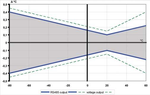
DTR15 Ground Radiation Shield DTR15 is designed to reflect direct solar radiation by means of its highly reflective white surface. It is used to protect the DTS12G Ground/Soil Temperature Probe from solar radiation and rain. The shield is fastened to its location by inserting its 3 stainless steel spikes into the ground.
Radiation Shield Features • Fiberglass-filled polyester •Excellent•UV-proof ventilation • Water-repellent
DTR13 and DTR15 Radiation Shields
DTR13
DTR15 Ground Radiation Shield
Vaisala DTR13 and DTR15 radiation shields are designed for protecting probes and sensors against solar radiation and rain.
DTS12A Air Temperature Probe, and also environmental sensors by other manufacturers. The radiation shield is tested to withstand vibration according to IEC 6-2 (Fc, sinusoidal vibration).
The naturally ventilated, maintenancefree DTR13 provides protection from scattered as well as direct solar radiation and rain. The material is fiberglass-filled polyester designed to offer excellent thermal characteristics and a durable UV-proof construction. The outer surface is painted white to reflect radiation while the inside is black to absorb accumulated Theheat.design of DTR13 enables easy installation and mounting. DTR13 can be used with Vaisala HMP155 Temperature and Humidity Probe, 163
DTR13 Radiation Shield
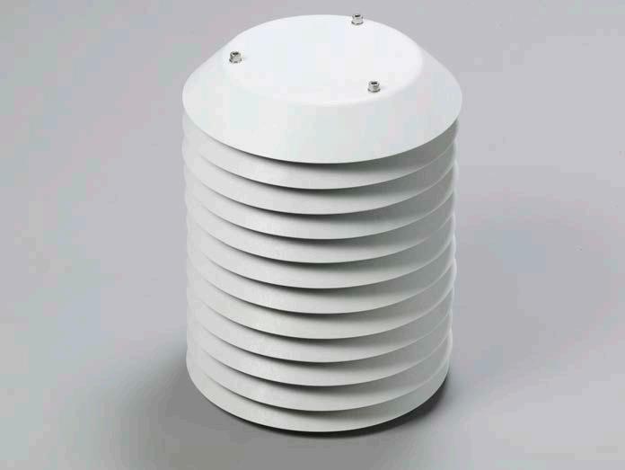
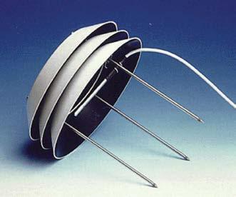
Inner height 223 mm (8.78 in) Weight 1.9 kg (4.19 lb)
DKPFIXP44H mounting arm for 60, 75 and 100-mm (2.36, 2.95, and 3.94 in) pole mast or wall mounting
DTR15 installation Spikes inserted into ground
DTR15 radiation shield dimensions
HMP155 inside DTR13 on Sensor Support HMP155 inside DTR13 on DKPFIXP44H www.vaisala.com 164
Outer diameter 220 mm (8.66 in) Outer height 110 mm + 180 mm spikes (4.33 in + 7.09 in) Inner diameter 110 mm (4.33 in) Inner height 50 mm (1.97 in) Weight 1.4 kg (3.09 lb)
DTR13 radiation shield dimensions
Outer diameter 220 mm (8.66 in) Outer height 300 mm (11.81 in) Inner diameter 110 mm (4.33 in)
DKP060SUP1 sensor support arm, square tube, for 60-mm (2.36 in) pole mast
DTR13 and DTR15 Technical Data
DTR13 installation
DKP12SUP1 sensor support arm, square tube, for 100-mm (3.94 in) pole mast
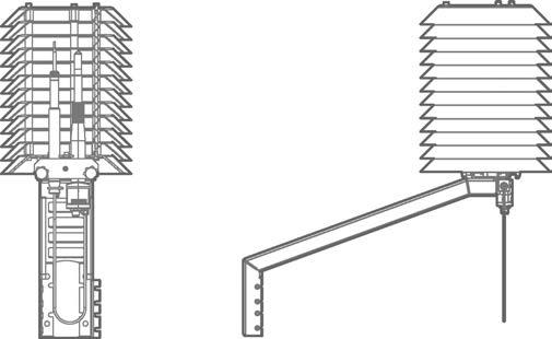
Vaisala HUMICAPâ Humidity and Temperature Probes HMP3 and VaisalaHMP7 Combined Pressure, Humidity and Temperature Transmitters PTU303 and PTU307 DTR503(A)
Vaisala HUMICAPâ Humidity and Temperature Probe HMP155 DTR504(A)
Vaisala HUMICAPâ Humidity and Temperature Transmitters VaisalaHMT120/130HUMICAPâ Humidity and Temperature Probe HMP110
a wide selection of •Choiceapplicationsofshields and mounting accessories Sensor
Vaisala INTERCAPâ Humidity and Temperature Probe HMP60
Vaisala Radiation Shield Series DTR500 are solar radiation and precipitation shields supporting humidity probe installations in outdoor applications. 165
The special plastic used in the plates has excellent thermal characteristics: the white outer surface reflects radiation, and the black inside absorbs accumulated heat. The shields can be easily installed on a vertical pole, horizontal beam, or flat surface.
The DTR shields can be used with the following Vaisala products: DTR502(A) with adapter 221072
Solar
The maintenance-free DTR500 series shields protect the humidity and temperature sensors from solar radiation and precipitation. They provide excellent ventilation while blocking both direct and reflected solar radiation.
•Suitable
DTR500 Radiation and Precipitation Shields horizontal beam, or flat surface for protection
Vaisala HUMICAPâ Humidity and Temperature Probe HMP155's additional temperature sensor DTR502B Vaisala HUMICAPâ Humidity and Temperature Transmitters HMT333, HMT337, HMT373, and HMT377
Features •Protection for temperature and humidity probes from scattered and direct solar radiation and rain •Easy•Naturally•Maintenance-freeventilatedtoinstallonavertical pole,
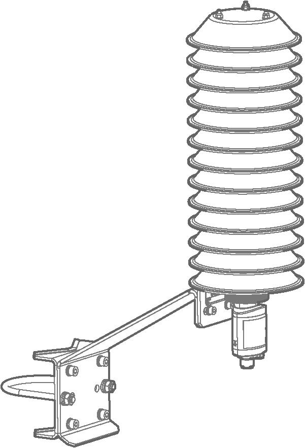
Technical data DTR502B for HMT333, HMT337, HMT373, HMT377, HMP3, HMP7, PTU303, and PTU307 Dimensions (H × W) 195 × 105 mm (7.68 × 4.13 in) Accessories Product specific adapter 213 [8.39] 105 [4.13] [7.68]195 [14]356 DTR502B dimensions DTR504 for HMT120/130 remote probes, HMP110, and HMP60 Dimensions (H × W) 141 × 105 mm (5.55 × 4.13 in) Accessories Horizontal beam assembly Pole mast installation kit Ø105 [4.13] [3.94]100[5.55]141 DTR504 dimensions DTR503A for HMP155 Dimensions (H × W) 252 × 105 mm (9.92 × 4.13 in) Accessories Horizontal beam assembly Pole mast installation kit ]16.24[413 Ø105 [ 4.13 ] ]9.92[252 216 [ 8.52 ] DTR503A dimensions www.vaisala.com 166
The excellent long-term stability of the barometer minimizes or even removes the need for field adjustment in many applications. 167
Vaisala BAROCAP Technology PTB110 uses the Vaisala BAROCAP sensor, a silicon capacitive absolute pressure sensor developed by Vaisala for barometric pressure measurement applications. The sensor combines the outstanding elasticity characteristics and mechanical stability of single-crystal silicon with the proven capacitive detection principle.
PTB110 BAROCAP Barometer Features •Vaisala BAROCAPâ sensor •Several pressure ranges • Accuracy ±0.3 hPa at +20 °C •Long-term stability • On/Off control with external •Outputtrigger voltage 0 … 2.5 or 0 … 5 •CurrentVDCconsumption less than 4 •MountablemA on 35 mm wide DIN •Traceablerail(certificatecalibrationincluded)
Vaisala BAROCAPâ Barometer PTB110 is designed both for accurate barometric pressure measurements at room temperature and for general environmental pressure monitoring over a wide temperature range.
Applications PTB110 is suitable for a variety of applications, such as environmental pressure monitoring, data buoys, laser interferometers, and agriculture and hydrology. The compact PTB110 is ideal for data logger applications as it has low power consumption. The external On/Off control is practical when electricity supply is limited.
Accuracy and Stability
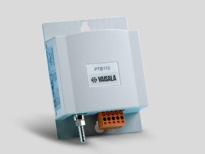
Operating environment Operating temperature −40 … +60 °C (−40 … +140 °F) Storage temperature −40 … +60 °C (−40 … +140 °F) Operating humidity Non condensing IP rating IP32 EMC compatibility EN 61326 1, industrial environment
Materials Housing cover Plastic ABS/PC blend Mounting plate Aluminum Inputs and outputs Supply voltage 10 … 30 V DC Supply voltage control With TTL level (Transistor-TransistorLogic) trigger Supply voltage sensitivity Negligible Average power consumption 0.10 W at 12 V Output voltage 0 … 2.5 V DC 0 … 5 V DC Output frequency 500 … 1100 Hz Pressure connector M5 (10 … 32) internal thread Pressure fitting Barbed fitting for ⅛ in Minimum pressure limit 0 hPa abs Maximum pressure limit 2000 hPa abs Electrical connector A removable connector for 5 wires (AWG 28 … 16)
Terminals Pin 1: External triggering Pin 2: Signal ground Pin 3: Supply ground Pin 4: Supply voltage Pin 5: Voltage/Frequency output Dimensions www.vaisala.com 168
Mechanical specifications Dimensions (H × W × D) 97.3 × 68.4 × 28.1 mm (3.83 × 2.69 × 1.10 in) Weight 90 g (3.2 oz)
performance
Pressure range (1 hPa= 1 mbar)500 … 1 100 hPa 600 … 1100 hPa 800 … 1100 hPa 800 … 1060 hPa 600 … 1060 hPa Resolution 0.1 hPa Load resistance 10 000 Ω minimum Load capacitance 47 nF maximum Settling time to full accuracy after startup 1 s Response time to full accuracy after a pressure step 500 ms Acceleration sensitivity Negligible Accuracy Linearity 1) ±0.25 hPa Hysteresis 1) ±0.03 hPa Repeatability 1) ±0.03 hPa Pressure calibration uncertainty 2) ±0.15 hPa Voltage calibration uncertainty±0.7 mV Frequency calibration uncertainty±0.3 Hz Accuracy at +20 °C (+68 °F) 3) ±0.3 hPa Total accuracy at +15 … +25 °C (+59 … +77 °F) ±0.3 hPa 0 … +40 °C (+32 … +104 °F) ±0.6 hPa −20 … +45 °C (−4 … +113 °F) ±1.0 hPa −40 … +60 °C (−40 … +140 °F)±1.5 hPa Long-term stability ±0.1 hPa / year 1) Defined as ±2 standard deviation limits of end-point non-linearity, hysteresis error, or repeatability error. 2) Defined as ±2 standard deviation limits of inaccuracy of the working standard including traceability to international standards. 3) Defined as the root sum of the squares (RSS) of end-point non-linearity, hysteresis error, repeatability error, and calibration uncertainty at room temperature.
Technical Data Measurement
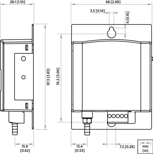
Several pressure ranges PTB210 is designed for various pressure ranges. It is available in 2 pressure ranges in 3 •Serialconfigurations:outputfor500 … 1100 hPa •Serial output for 50 … 1100 hPa
Vaisala BAROCAP technology
•Analog output with different scalings between 500 … 1100 hPa Accurate and stable measurement
PTB210 BAROCAP Digital Barometer Features •500 … 1100 hPa or 50 … 1100 hPa pressure ranges with serial output • Different scalings between 500 … 1100 hPa with analog •Electronicsoutputhousing IP65 protected against sprayed water •Accurate and stable measurement •Traceable(certificatecalibrationincluded)
PTB210 is digitally adjusted and calibrated by using electronic working standards. A higher accuracy barometer, which is fine-tuned and calibrated against a high-precision pressure calibrator, is available for the 500 … 1100 hPa pressure range.
In addition, PTB210 integrates directly with Vaisala Static Pressure Head Series SPH10/20. This pairing offers accurate measurement in all wind conditions.
PTB210 paired with SPH10 static pressure head 169
Vaisala BAROCAPâ Digital Barometer PTB210 is a reliable outdoor barometer for harsh conditions. For harsh environments PTB210 is ideal for outdoor installations and harsh environments. PTB210 is designed to operate in a wide temperature range, and the electronics housing provides IP65 (NEMA 4) standardized protection against sprayed PTB210water. is ideal for use in applications such as weather stations, data buoys, ships, airports, and agrology. It is also an excellent solution for monitoring barometric pressure in industrial equipment such as laser interferometers and engine test benches.
PTB210 uses the Vaisala BAROCAP sensor, a silicon capacitive absolute pressure sensor developed by Vaisala for barometric pressure applications. The Vaisala BAROCAP sensor provides excellent hysteresis and repeatability characteristics and outstanding temperature and long-term stability.
PTB210 is delivered with a traceable factory calibration certificate.
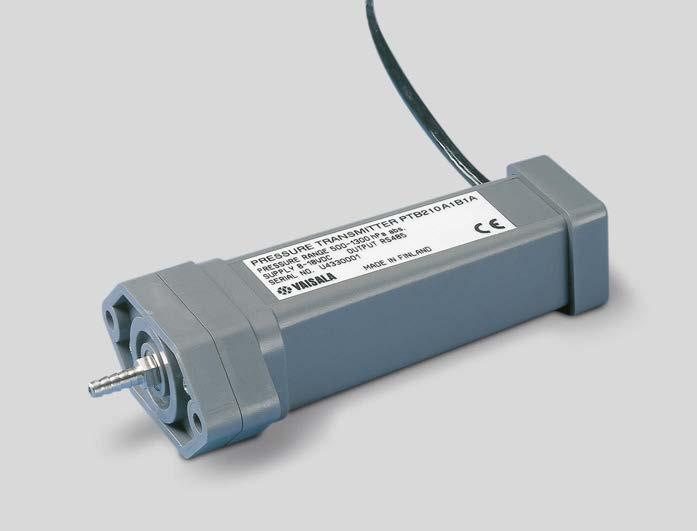
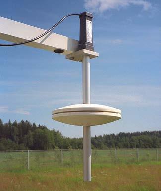
Current consumption, normal mode< 15 mA (factory setting)
Parity None, even, odd Data bits 7, 8 Stop bits 1, 2 Baud rate 1200, 2400, 4800, 9600, 19200 Response time 1 s Resolution 0.01 hPa (1 measurement/s) 0.03 hPa (10 measurements/s)
performance
All models Max. pressure 5 000 hPa absolute Pressure connector M5 (10-32) internal thread Pressure fitting Barbed fitting for 1/8 in I.D. tubing Supply (reversevoltagepolarity protected), with RS-232/TTL output 5 … 28 V DC Supply (reversevoltagepolarity protected), with RS-485 or analog output 8 … 18 V DC
Compliance Directives EMC Directive (2014/30/EU) RoHS Directive (2011/65/EU)
4) Defined as ±2 standard deviation limits of temperature dependence over the operating temperature range.
Cable weight 28 g/m (1.0 oz)
Housing material PC plastic IP rating, electronics IP65 (NEMA 4) IP rating, sensor IP53 Weight, sensor 110 g (3.9 oz)
Mechanical specifications
Shutdown ON/OFF Response time 500 ms Resolution 300 μV Measurement rate 3 measurements/s
Analog output Outputs 0 … 5 V DC, 0 … 2.5 V DC (order specified)
1) Defined as the ±2 standard deviation limits of end point non-linearity, hysteresis error, or repeatability error. 2) Defined as ±2 standard deviation limits of inaccuracy of the working standard including traceability to international standards. 3) Defined as the root sum of the squares (RSS) of end point non-linearity, hysteresis error, repeatability error, and calibration uncertainty at room temperature.
Technical Data Measurement
Current consumption, normal mode< 8 mA Current consumption, shutdown mode0.2 mA
Pressure range Serial output 500 … 1100 hPa 50 … 1100 hPa Analog output 500 … 1100 hPa 600 … 1060 hPa 800 … 1060 hPa 900 … 1100 hPa Serial output, accuracy (hPa) Pressure range500 … 1100 50 … 1100 Class A Class B Non-linearity 1) ± 0.10 ± 0.15 ± 0.20 Hysteresis 1) ± 0.05 ± 0.05 ± 0.10 Repeatability 1) ± 0.05 ± 0.05 ± 0.10 uncCalibrationertainty 2) ± 0.07 ± 0.15 ± 0.20 Accuracy at +20 °C (+68 °F) 3) ± 0.15 ± 0.20 ± 0.35 dependencTemperaturey 4) ± 0.20 ± 0.20 ± 0.40 Total accuracy -40 … +60 °C (-40 … +140 °F) 3) ± 0.25 ± 0.30 ± 0.50 year)sLong-termtability(hPa/ ± 0.10 ± 0.10 ± 0.20 Analog output, accuracy Non-linearity 1) ± 0.20 hPa Hysteresis 1) ± 0.05 hPa Repeatability 1) ± 0.05 hPa Calibration uncertainty 2) ± 0.15 hPa Accuracy at +20 °C (+68 °F) 3) ± 0.30 hPa Temperature dependency 4) ± 0.50 hPa Total accuracy -40 … +60 °C (-40 … +140 °F) 3) ± 0.60 hPa Long-term stability ± 0.10 hPa/year
Operating environment Operating temperature −40 … +60 °C (−40 … +140 °F) Operating humidity 0 … 100 %RH, non condensing
Serial output Shutdown ON/OFF Settling time at startup 2 s Serial I/O RS-RS-232C232C / TTL (optional) RS-485, non-isolated (optional)
170
EMC compatibility EN / IEC 61326-1, Electrical equipment for measurement, control and laboratory use - EMC requirement; Basic CISPRenvironment32/EN55032, Class B Compliance CE, FCC, UKCA www.vaisala.com
Current consumption, shutdown mode0.2 mA
Inputs and outputs
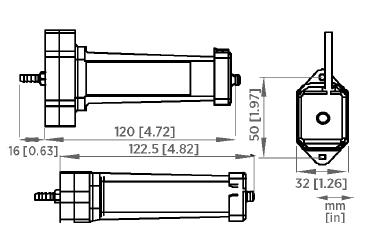
According to your choice, PTB330 can incorporate 1, 2, or 3 BAROCAP sensors. When 2 or 3 sensors are used, the barometer continuously compares the readings of the pressure sensors against one another and reports if they are within the set internal difference criteria. This unique feature provides redundancy in pressure measurement. Users also get a stable and reliable pressure reading at all times as well as a pre-indication of when to service or recalibrate the barometer.
Highly Accurate
QNH and QFE PTB330 can be set to compensate for QNH and QFE pressure used especially in aviation. The QNH represents the pressure reduced to sea level, based on the altitude and temperature of the observation site. The QFE represents the height-corrected pressure of small differences in altitude, for example, the air pressure at the airfield elevation.
171
The PTB330 series is highly accurate. Class A barometers for the most demanding applications are fine-tuned and calibrated against a high-precision pressure calibrator. Class B barometers are adjusted and calibrated using an electronic working standard. All PTB330 barometers come with a traceable factory calibration certificate. Reliability Redundancythrough
Graphical Display PTB330 features a multilingual, graphical display allowing users to monitor measurement trends. PTB330 updates the graph automatically during measurement and it provides a one-year measurement history. In addition to instant pressure, PTB330 provides the WMO pressure trend and tendency codes. Applications PTB330 can be used successfully for aviation, professional meteorology, and for demanding industrial pressure measurement applications such as accurate laser interferometric measurement and exhaust gas analysis in engine test benches.
Vaisala BAROCAPâ Digital Barometer PTB330 is a new-generation barometer, designed for a wide range of high-end atmospheric pressure measurement. The pressure measurement of PTB330 is based on the Vaisala silicon capacitive, absolute pressure sensor - the Vaisala BAROCAP sensor. It provides high measurement accuracy and excellent long-term stability.
PTB330 BAROCAP Digital Barometer Features •Vaisala BAROCAPâ sensor •Accurate measurement • Excellent long-term stability •Added reliability through •Graphicalredundancytrend display with 1year history data •Height and altitude corrected pressure (QFE, QNH) •For professional meteorology and aviation, laboratories, demanding industrial applications
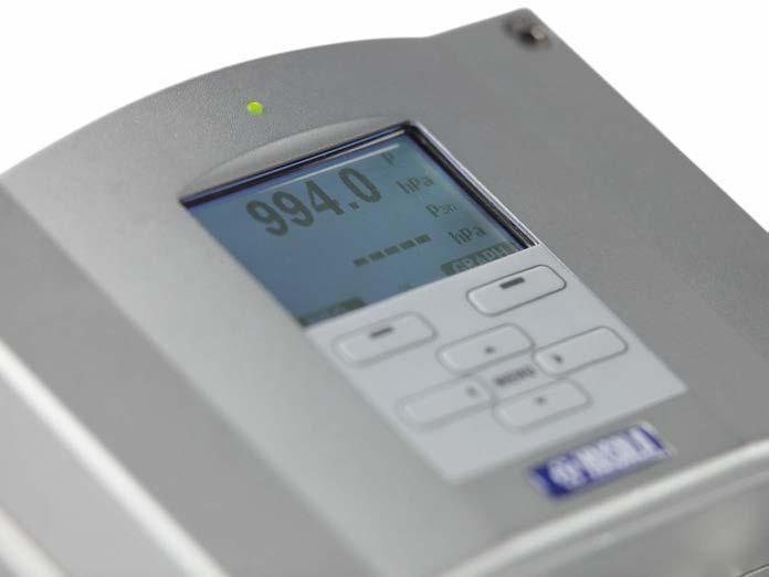
2) Defined as ±2 standard deviation limits of inaccuracy of the working standard including traceability to international standards.
Operating temperature with local display 0 … +60 °C (+32 … +140 °F) IP rating IP65IP66 (NEMA4) with local display EMC compatibility EN 61326 1, industrial environment
Property Class A Class B Barometric pressure range 500 … 1100 hPA Linearity 1) ±0.05 hPa ±0.10 hPa Hysteresis 1) ±0.03 hPa ±0.03 hPa Repeatability 1) ±0.03 hPa ±0.03 hPa Calibration uncertainty 2) ±0.07 hPa ±0.15 hPa Accuracy at +20 °C (+68 °F) 3) ±0.10 hPa ±0.20 hPa Barometric pressure range 50 … 1100 hPA Linearity 1) ±0.20 hPa Hysteresis 1) ±0.08 hPa Repeatability 1) ±0.08 hPa Calibration uncertainty 2) ±0.15 hPa Accuracy at +20 °C (+68 °F) 3) ±0.20 hPa Temperature dependence 4) 500 … 1100 hPa ±0.1 hPa 50 … 1100 hPa ±0.3 hPa Total accuracy −40 … +60 °C (−40 … +140 °F) 500 … 1100 hPa ±0.15 hPa ±0.25 hPa 50 … 1100 hPa ±0.45 hPa Long-term stability 500 … 1100 hPa ±0.1 hPa/year 50 … 1100 hPa ±0.1 hPa/year Miscellaneous Pressure units hPa, mbar, kPa, Pa inHg, mmH20, mmHg, torr, psia hPa, mbar, kPa, Pa inHg, mmH20, mmHg, torr, psia Resolution 0.01 hPa 0.1 hPa Settling time at startup (one sensor) 4 s 3 s Response time (one sensor)2 s 1 s Acceleration sensitivity– Negligible Maximum pressure limit– 5000 hPa absolute
Data transfer software MI70 Link Interface software requirements Microsoftâ Windows OS Microsoftâ Excel Mechanical specifications
Inputs and outputs
Supply voltage 10 … 35 V DC Supply voltage sensitivity Negligible Typical power consumption at +20 °C (+68 °F) (Uin 24 V DC, one pressure sensor) RS 232: 25 mA RS 485: 40 mA Uout: 25 mA Iout: 40 DisplaymAand backlight: +20 mA Serial I/O RS 232C, RS 485, RS 422 Analog output (optional)
Technical Data Measurement performance
3) Defined as the root sum of the squares (RSS) of endpoint non-linearity, hysteresis error, repeatability error, and calibration uncertainty at room temperature.
Housing material G AlSi10 Mg (DIN 1725) Weight 1 … 1.5 kg (2.2 … 3.3 lb)
Operating environment Pressure range 500 … 1100 hPa, 50 … 1100 hPa Operating temperature −40 … +60 °C (−40 … +140 °F)
4) Defined as ±2 standard deviation limits of temperature dependence over the operating temperature range.
www.vaisala.com 172
1) Defined as ±2 standard deviation limits of endpoint non-linearity hysteresis, or repeatability error.
Current output 0 … 20 mA, 4 … 20 mA Voltage output 0 … 1 V, 0 … 5 V, 0 … 10 V Accuracy at pressure range 500 … 1100 hPa 50 … 1100 hPa At +20 °C (68 °F)±0.30 hPa ±0 40 hPa At −40 … +60 °C (-40 … 140 °F) ±0.60 hPa ±0.75 hPa Accessories Serial interface cable 19446ZZ USB RJ45 serial connection cable219685 Software interface kit 215005 Wall mounting kit 214829 Outdoor installation kit (weather shield) 215109 Installation kit for pole or pipeline215108 Power supply module POWER 1 Temperature compensated analog output module AOUT 1T Isolated RS 485 module RS485 1 DIN rail kit 215094
Pressure fitting Barbed fitting for ⅛ inch I.D. tubing or quick connector with shutoff valve for ⅛ inch hose Pressure connector M5 (10 32) internal thread
•USB service cable for connecting to PTB330 service port
•ISO/IEC 17025 Accredited calibration for PTB330
•Servicedisplay
PTB330TS is suitable for reference measurements in industrial and meteorological areas. PTB330TS is housed in a durable and weatherproof transport case that can be easily carried and shipped. The components of the PTB330TS are placed in a foam interior with accessories and User Guide in the lid organizer. The case includes a shoulder strap.
•Vaisala
•Weatherproof
•MI70 Link software and USB or RS 232 cable for downloading measurement data to a computer
•Handheld
PTB330TS Barometric Pressure Transfer Standard digital barometer for accurate pressure measurement MI70 indicator with a user-friendly, multilingual port for MI70 Link software or computer HUMICAPâ humidity and temperature probe HMP155 transport case
173
•HMP155 options: additional temperature probe, manually controlled chemical purge feature
For Measurements in Industrial and Meteorological Areas
Available Options
Features •PTB330
Barometric Pressure Transfer Standard PTB330TS combines a PTB330 digital barometer with a handheld MI70 indicator into a portable unit that can be used as a transfer standard. Barometer for Portable Use PTB330TS uses a PTB330 series digital barometer that is housed in a tabletop casing. PTB330TS is designed to be operated using the handheld MI70 indicator. The MI70 indicator also provides the operation power for the barometer. Optional HMP155 probe is available for accurate humidity and temperature measurement.
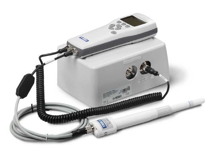
Continuous use with PTB330 11 h typical at +20 °C (+68 °F) Datalogging use Up to 30 days -20 0 20 40-0,1-0,2-0,300,30,20,1
Measurement range −10 ... +40 °C (+14 ... +104 °F) −10Accuracy...+20 °C (+14 ... +68 °F) ±(0.176 - 0.0028 x temperature) °C +20 ... +40 °C (+68 ... +104 °F)±(0.07 + 0.0025 x temperature) °C
Response time at +20 °C (+68 °F) in still air with a sintered PTFE filter 63% 20 s 90% 60 s Temperature (HMP155)
HUMICAP180RCHUMICAP180R
General Operating temperature HMP155PTB330MI70 −10 ... +40 °C (+14 ... +104 °F) −40 ... +60 °C (−40 ... +140 °F) −80 ... +60 °C (−112 ... +140 °F)
Available Parameters
These specifications apply when MI70, PTB330, and HMP155 are used together in PTB330TS. For PTB330 and HMP155 specifications, see the product documentation.
Temperature sensor Pt100 RTD Class F0.1 IEC 60751 Response time with additional temperature probe in 3 m/s air flow 63% < 20 s 90% < 35 s
Accuracy of HMP155 temperature measurement over temperature range Measurement Performance Barometric Pressure (PTB330) Measurement range 500 ... 1100 hPa Linearity 1) ±0.05 hPa Hysteresis 1) ±0.03 hPa Repeatability 1) ±0.03 hPa Calibration uncertainty 2) ±0.07 hPa Accuracy at +20 °C (+68 °F) 3) ±0.10 hPa Temperature dependence 4) ±0.1 hPa Total accuracy -40 ... +60 °C (-40 ... +140 °F) ±0.15 hPa Long-term stability ±0.1 hPa/year Settling time at startup (one sensor)4 s Response time (one sensor) 2 s
2) Defined as ±2 standard deviation limits of inaccuracy of the working standard including traceability to NIST. 3) Defined as the root sum of the squares (RSS) of endpoint non-linearity, hysteresis error, repeatability error, and calibration uncertainty at room temperature.
Operation Time (Using Rechargeable Battery Pack)
Operating humidity Non-condensing Maximum pressure limit 5000 hPa abs. Power supply Rechargeable NiMH battery pack with AC-adapter or 4xAA-size alkalines, type IEC LR6 Menu languages English, Chinese, French, Spanish, German, Russian, Japanese, Swedish, Finnish Display LCD with backlight, graphic trend display of any parameter, character height up to 16 mm Data logging capacity 2700 points Alarm Audible alarm function Compliance •EMC Directive (2004/108/EC) Complies with the EMC product family standard EN61326 1 •Electrical equipment for measurement control and laboratory use •Basic immunity test requirements •Low Voltage •ROHS(2006/95/EC)DirectiveDirective(2002/95/EC)
Technical Data
4) Defined as ±2 standard deviation limits of temperature dependence over the operating temperature range. 5) Defined as ±2 standard deviation limits. Small variations possible, see also calibration certificate.
MI70 probe ports 2 MI70 data interface RS-232 (accessible only with MI70 Link software)
Pressure parameters P, P3h, HCP, QFE, QNH Humidity and temperature parametersRH, T, Tdf, Td, x, Tw Inputs and Outputs
PTB330 supply voltage 10 ... 35 VDC (if not powered by MI70)
Acceleration sensitivity Negligible Relative Humidity (HMP155)
Measurement range 0 ... 100 %RH Accuracy (incl. non-linearity, hysteresis and repeatability) at +15 ... +25 °C (+59 ... +77 °F)±1 %RH (0 ... 90 %RH) ±1.7 %RH (90 ... 100 %RH) at −10 ... +40 °C (−4 ... 104 °F) ±(1.0 + 0.008 reading) %RH Factory calibration uncertainty at +20 °C (+68 °F) ±0.6 %RH (0 ... 40 %RH) 5) ±1.0 %RH (40 ... 97 %RH) 5) Humidity sensor
1) Defined as ±2 standard deviation limits of endpoint non-linearity, hysteresis, or repeatability error.
PTB330 data interface RS 232C PTB330 serial I/O connectors RJ45 (service port) Male 8 pin M12 (user port) HMP155 data interface RS 485 HMP155 serial I/O connector Male 8 pin M12 174
∆ °C °C
175
PTB330 MI70 – PTB330 spiral cable 223235SP USB-RJ45 serial connection cable219685 Serial connection cable 19446ZZ Barbed fitting 1/8 in 19498SP Quick connector 1/8 in 220186 Transport case with interior foams and tabletop casing for PTB330 224068SP MI70 USB cable for MI70, includes MI70 Link software 219687 MI70 Link software MI70LINK MI70 connection cable to HMT330, MMT330, DMT340, HMT100, PTB330 211339 MI70 battery pack variety of AC adapters available 26755 HMP155 HMP155 - MI70 connection cable221801 Protection set for HMP155 calibration buttons: protective cover, 2 O-rings and protective plug 221318 USB cable for HMP155 221040 Sintered teflon filter + O-ring 219452SP Humidity sensor HUMICAP180R Humidity calibrator HMK15 www.vaisala.com
Specifications
Mechanical
PTB330 Housing material G-AlSi 10 Mg (DIN 1725) IP rating IP65 Pressure connector M5 (10-32) internal thread Pressure fitting Barbed fitting for 1/8 inch I.D. tubing or quick connector with shutoff valve for 1/8 inch hose HMP155 Housing material PC IP rating IP66 Additional T-probe cable length2 m (6 ft 6 in) Cable material PUR Sensor protection Sintered PTFE MI70 Measurement Indicator IP rating IP54 Housing material ABS/PC blend Transport Case IP rating (when closed) IP67 Plastic parts TTX01â, PP+SEBS, POM Metal parts Stainless steel AISI303 Interior foam material Polyethylene and polyether Weight with all instruments and typical accessories 5 9 kg (13 lb) Exterior dimensions (L × W × H) 405 × 330 × 165 mm (15.94 × 12.99 × 6.50 in) Spare Parts and Accessories
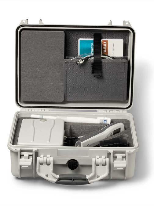
176
•Reliable
•Easy
SPH10 and SPH20 Static Pressure Head Series
•Wind
•Easy
Features •Minimizes
Vaisala static pressure heads are available in two models: Vaisala Static Pressure Head SPH10 is a basic version, and Vaisala Static Pressure Head SPH20 is a heated version for reliable operation in snowy and icy conditions. The heated SPH20 contains a thermostat that switches on the warming power at temperatures where the risk of icing may Composedoccur. of ultraviolet stabilized PC plastics and offshore aluminum, SPH10/20 static pressure heads are durable and weather resistant.
SPH10/20 Static Pressure Heads minimize the e ects of wind on barometric pressure readings.
SPH10/20 protects against rain and condensed water. This prevents capillary condensation of a water column in the pressure channel resulting in a pressure error. The drain holes in the lower plate allow rain and water to flow out. The static pressure heads have internal netting that prevents insects and debris from blocking the pressure channel. Carefree Maintenance SPH10/20 static pressure heads are easy to install and disassemble, service, and clean – even at the installation site.
SPH10/20 is easy to install and connect. In the picture, SPH10 is connected to PTB210. wind induced error barometric pressure measurement in all weather tunnel tested structure to clean to install Wind induced effects are one of the main sources of error when measuring barometric pressure. Variations due to strong and gusty wind can be overcome by using a static pressure head to reduce the effect of dynamic pressure. Vaisala Static Pressure Head Series SPH10/20 are designed to minimize the errors caused by wind. Their wind tunnel tested structure is both horizontally and vertically symmetrical. This design ensures reliable barometric pressure measurements in all weather.
Vaisala BAROCAPâ Digital Barometer PTB210 can be installed directly on top of SPH10/20 static pressure heads. Other barometers can be connected to the heads with pressure tubing. SPH10 and SPH20 are a perfect pair for all Vaisala barometers. They ensure an accurate and reliable measurement in all weather conditions.
Ideal for Outdoor Installations
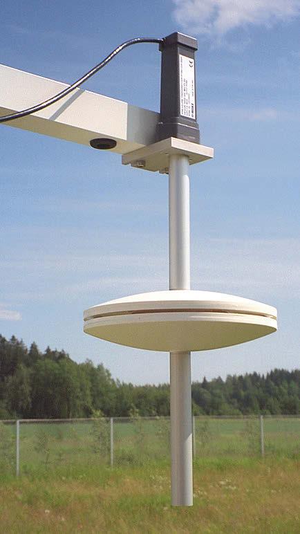
Technical Data Operating Environment Operating temperature -60 … +80 °C (-76… +176 °F)
Hose connection Barbed fitting for 4 mm I.D. hose or Rp1/4 thread (parallel)
SPH20 Inputs and Outputs
On +4 °C (±3 °C) +39.2 °F (±4.4 °F) Off +13 °C (±3 °C) +55.4 °F (±4.4 °F)
Dimensions in mm (inches) SPH10 [14.61] [5.67]144 [5.94][2.36] [1.57] [1.61]103.5 [4.07] [0.26] [7.87]ø200 [1.50] [0.87][18.35] 15160371 466 M640 41 3822 6.5 SPH20
www.vaisala.com 177
Mechanical Specifications Weight SPH10: 800 g (1.76 lb) SPH20: 1360 g (3.0 lb)
Materials PC plastic, offshore aluminium Mounting With 2 bolts (M6 × 20 mm min.)
Thermostat Switching Temperature
Electrical connections M12 connector Power supply Factory setting: 12 V Changed connection: 24 V Power consumption during heating 70 W
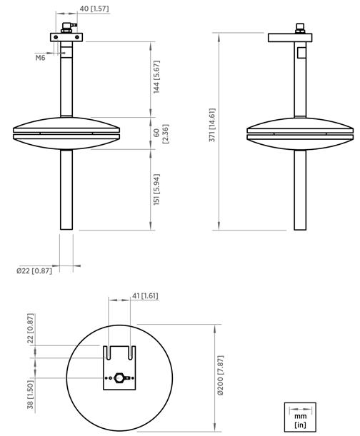
Vaisala Rain Gauge RG13 and Vaisala Rain Gauge RG13H with heating option are designed for measuring liquid precipitation.
RG13 and RG13H Rain Gauge Features •Designed to measure rainfall / liquid •Robust•Economical•Provides•Suitable•Tippingprecipitationbucketprincipleforremoteandunattendedlocationsaccuratemeasurementsandproveninoperationsystemcomponent
RG13(H) uses a pulse-based tippingbucket mechanism to produce a contact closure every time it receives a predetermined quantity of rainfall: 0.1 mm (0.004 in) or 0.2 mm (0.008 in).
A siphon device is fitted to the base of the funnel to control the rate of flow into the buckets. By ensuring a constant flow rate into the tipping bucket, calibration is made easier and accuracy improved. The gauge is available with or without the heating function. The heating turns on when the temperature drops below +4 °C (+39 °F).
The body and funnel of the gauge are aluminum alloy. The septum ring at the top gives an aperture of exactly 400 cm2 (62 in2). The tipping-bucket mechanism is mounted inside the body on a cast aluminum-alloy base that has fixing slots, 3 leveling screws, and a spirit level.
The mechanism consists of a divided bucket pivoted at its center. Rain collects in the upper half. When this is full, the mechanism tilts and discharges the collected water, so that the other half of the bucket can start filling.
178
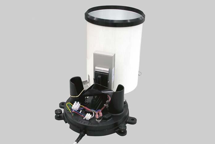
Material Base, septum ring Aluminum alloy LM25 Outer ring, funnel Aluminum alloy sheet Inlet/Outlet ports, pins Stainless steel Tipping mechanism Injection-moulded plastic Transducer Reed switch Output Circuit Contact closure Connection Screw terminal www.vaisala.com
179
Dimensions (H × Ø) 338 × 248 mm (13.31 × 9.76 in) Weight 2.6 kg (5.73 lb)
Heating connection/disconnection at+4 °C (+39 °F) Heating power RG13H: 33W / 48 V DC Mechanical specifications
Precipitation Liquid Accuracy 2 % at 1 l/h (0.26 gal/h) Diameter of aperture 225 mm (8.86 in) Area of aperture 400 cm2 (62 in2) Rainfall capacity Unlimited Resolution 0.2 mm (0.008 in) 0.1 mm (0.004 in)
Operating environment Operating temperature RG13H: −20 … +85 °C (−4 … +185 °F) Storage temperature −40 … +85 °C (−40 … +185 °F) Heating (RG13H)
Technical Data Measurement
performance
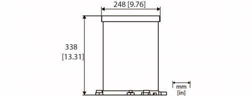
Rain Gauge QMR101M for MAWS201M
For harsh conditions Manufactured from UV resistant plastic, QMR101(M) is a very rugged instrument that can withstand frost and icy Theconditions.raingauge is installed on a sensor support arm and it is delivered with a ready-made 1 meter (3 foot 4 inch) connector cable.
Portable rain gauge Due to its small size, weight, and rugged design, QMR101(M) is especially suitable for portable applications and temporary installations. It is economical as well as Theaccurate.raingauge uses the self-emptying tipping spoon mechanism to measure the collected rain at 0.2 millimeter (0.008 inch) accuracy level.
180
Vaisala Rain Gauge QMR101 and QMR101M are durable solutions for gathering accurate precipitation data. QMR101 is part of Vaisala HydroMet™ Automatic Weather Station MAWS201 while QMR101M is for Vaisala TacMet™ Tactical Meteorological Observation System MAWS201M.
QMR101 and
QMR101M Rain Gauge Rain Gauge QMR101 for MAWS201 Features •Provides accurate precipitation •Enclosure•Weatherproofdatafrom corrosion and UV resistant plastic •Suitable for installationstemporary
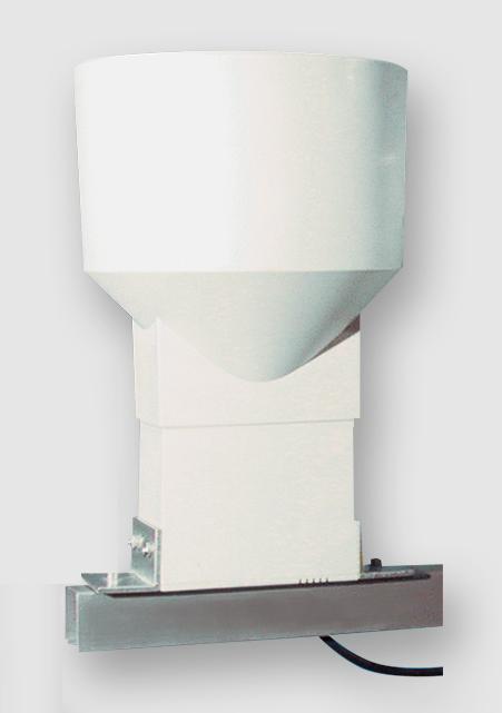
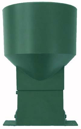
Funnel diameter 159.6 mm (6.28 in) Orifice area 200 cm2 (31 in2) UV stabilized plastic Connector QMR101: QMR101M:M12/5FAlden Pulse Lokâ V1, V114, 4P Cable 1 m (3 ft 4 in) Weight 0.380 kg (0.84 lb)
Material
RoHS
www.vaisala.com 181
EMC compatibility EN
1 Compliance marks CE Mechanical specifications
Technical data Measurement performance
industrial environment Electrical safety EN
Accuracy
Compliance EU directives and regulationsEMC
Sensor/Transducer type Self-emptying tipping spoon/magnet Sensitivity 0.2 mm (0.008 in) Capacity 144 mm/h (5.67 in/h) ±2 % Directive (2014/30/EU) Directive (2011/65/EU) amended by 2015/863 61326 1, 61010
Probe variants
The measurement accuracy and stability of QMT102, QMT103, and QMT110 are based on a Pt100 type sensor element, which is specified to a level of precision of 1/4 IEC 60751 Class B. The probe includes a cable with a black, weatherresistant polyurethane (PUR) sheath that withstands both abrasive wear and extreme temperatures. A 5 pin watertight connector is molded to the other end of the cable for quick installation and replacement in Vaisala weather stations.
182
All the materials used in the probe's manufacture have been carefully selected to withstand various types of environmental stress and a wide range of temperatures. Highly accurate measurements
•QMT103:
•QMT102:
QMT102, QMT103, and QMT110 Soil/ Water Temperature Probes Features •The Pt100 sensor element type, specified accuracy level of 1/4 IEC 60751 Class B •Excellent accuracy, repeatability, and long-term stability •Wide operating temperature •Watertightrange (IP68) •Stable, highly accurate temperature sensor ideally suited for measuring soil, air, leaf and water •Calibrationtemperaturestraceable to international standards
The offering has the following probe variants with different cable lengths: 2 m (6 ft 7 in) 5 m (16 ft 5 in) 10 m (32 ft 10 in)
•QMT110:
Vaisala Soil/Water Temperature Probes QMT102, QMT103, and QMT110 are particularly well suited for the precision measurement of ground and soil temperatures.
Carefully selected materials
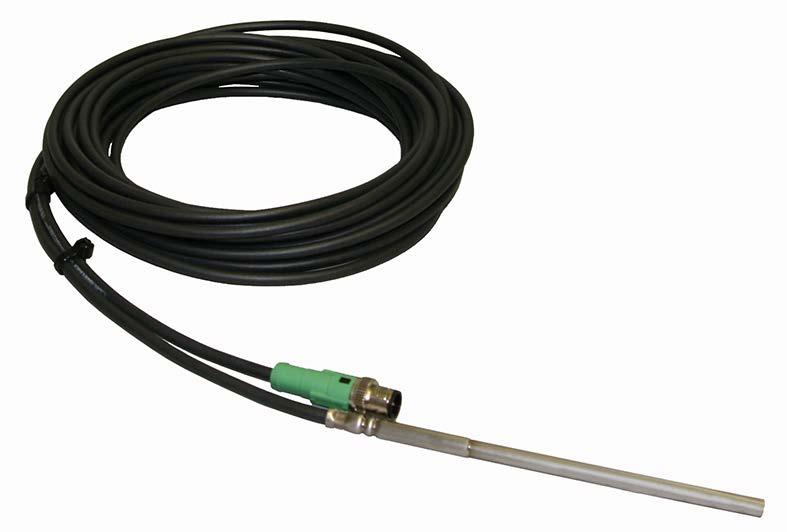
Operating environment
Operating temperature (fixed installation) −40 … +80 °C (−40 … +176 °F)
Operating temperature (flexible installation) −25 … +80 °C (−13 … +176 °F) IP rating IP68
Compliance marks CE Mechanical specifications
Material Stainless steel AISI 316 Cable Material Black polyurethane (PUR), 5 × 0 34 mm2 Cu Length • QMT102: 2 m (6 ft 7 in) • QMT103: 5 m (16 ft 5 in) • QMT110: 10 m (32 ft 10 in)
performance
Sensor type Pt100 type resistance temperature detector element Accuracy 1/4 IEC 60751 Class B > 0.08 °C at 0 °C (+32 °F) Sensitivity 0.385 Ω/°C (IEC 60751)
Technical data Measurement
Dimensions (L × Ø) 150 × 6 mm (5.91 × 0.24 in)
Compliance EU directives and regulations RoHS Directive (2011/65/EU) amended by 2015/863
www.vaisala.com 183
An all-in-one solution with many applications
Even without the optional NM10 software, it is possible to adjust settings and fix problems remotely. The AWS810 Web user interface allows the user to view basic station information, sensor status, and readings, to set site-specific parameters, and to perform many other functions using a graphical user interface.
AWS810 Automatic Weather Station Features •Complete solution for weather data •Excellentcollectionexpandability and •Modernflexibilitysecurity architecture •WMO compliant sensors and data •Includesvalidationthe next generation Vaisala Data Management Unit •EnhancedDMU801 remote maintenance and configuration management •Easy remote monitoring of network status using optional NM10 •Powerssoftwaremodern surface weather networks
184
Vaisala Automatic Weather Station AWS810 is a weather data collection system that automatically measures, processes, and stores meteorological data for professional use. AWS810 can be operated as a standalone unit, or it can be connected with other compatible Vaisala weather stations to form weather observation networks. AWS810 stations can be used for several applications, such as synoptic, aviation, and agricultural meteorology, hydrology, and climatology. Using the same standard hardware and software for many purposes lowers the cost of training, spare parts, and logistics support. Validated data from reliable sensors Vaisala weather stations and instruments are fully compliant with World Meteorological Organization guidelines. The design quality of Vaisala weather stations has been proven with extensive tests in the development phase and on the field. To ensure continuous accuracy of measurements and calculations, AWS810 includes built-in data quality controls that test sensor data against minimum and maximum limits and changes between successive measurements. The weather station’s DMU801 data management unit continuously monitors the status of the sensors to ensure measurement reliability, notifying the user if the status of any sensor becomes invalid. All the sensors operate independently from each other, meaning that an individual sensor failure does not affect the performance of the other sensors. Data security prioritized AWS810 provides first-class data security mechanisms to protect your data from security threats and unauthorized access. DMU801 data management unit brings along a number of data security features, such as secure network protocols, secure communication interfaces with industry standard encryption protocols, and dynamic firewall protection. Security development and maintenance, including regular firmware updates, is provided for continuous improvements. Maintenance made easier For AWS810 networks, the Vaisala Observation Network Manager NM10 software provides a powerful browserbased interface for 24/7 monitoring, access, and control of all your observation sites. Continuous, reliable observations improve the performance of your weather services and weathercritical operations, while shorter site visits and correct maintenance actions save time and money.
Vaisala Automatic Weather Station AWS810 has everything that you need for taking accurate and reliable weather measurements. It is a complete communication and data monitoring solution including sensors, electronics, mast, and power supply.
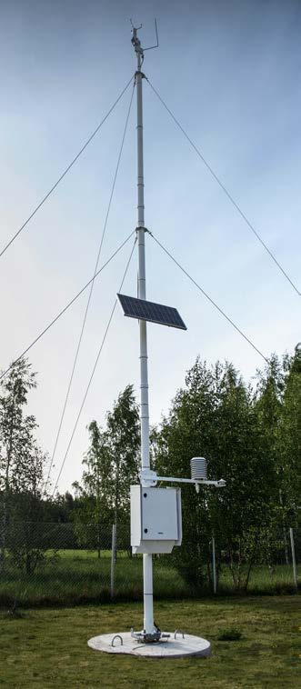
Immunity to voltage dips and short interrupts IEC 61000-4-110 % 1 cycle 40 % 10 cycles 70 % 25 cycles 0 % 250 cycles
Measurements
1)Modem Carrier Module DMX801 complies with EN 61326 1 basic level. Ethernet connection requires external surge protection to comply with EN 61326 1 industrial environment level.
Emissions radiated CISPR 32 Class B (EN 55032) 30 MHz … 2 GHz Emissions conducted to mains (AC) CISPR 32 Class B (EN 55032) 150 kHz … 30 MHz
Landline communication RS 232, RS 485, LAN Data collection software Vaisala Observation Network Manager NM10 Maintenance USB host device with Web UI
Wireless communication LTE Cat 4 cellular modem (with UMTS/HSPA+ and GSM/GPRS/EDGE support)
Powering specifications AC (mains) power 100 ... 240 V AC ±10 % 50 ... 60 Hz ±10 % 5.6 A maximum (120 V AC) Mains fuse (nominal) 10 A External DC 16 ... 28 V DC 10.6 A Heatedmaximumoption:24 V DC ±2 10.6 A maximum for system, 12 A maximum for heating Solar panel 70 W, typical 15 ... 28 V DC 6 A maximum (each), 10.6 A combined (both inputs) Internal backup battery 12 V / 26 Ah or 12 V / 52 Ah Backup battery fuse 10 A Overvoltage category II ENC652 specifications Approvals UL 50 / UL 50E-listing IP rating IP66 NEMA rating NEMA 4X Maximum operating wind speed75 m/s (168 mph) Door opening angle 100° Material Stainless steel AISI 316, painted white Size (enclosure only) 600 × 500 × 207 mm (23.62 × 19.68 × 8.15 in) Weight (excluding backup battery) < 30 kg (66 lb) 1) 1)Depends on the selected options.
Extended operating temperature (with insulated enclosure and heating) −60 ... +50 °C (−76 ... +122 °F), cold start at −40 °C (−40 °F) Storage temperature 2) 60 ... +70 °C (−76 ... +158 °F) Operating humidity 0 … 100 %RH Pollution degree 2
Environmental compliance Test Applied standard or test procedure Specification
Emissions conducted to telecommunication lines CISPR 32 Class B (EN 55032) 150 kHz … 30 MHz
Technical data
1)Excluding backup battery, QST102 3, cellular modem, QMN101, RG13(H), SR50A, and PAA 36 X W. See the manufacturer documentation. 2) Excluding cellular modem, HMP155, and HMP110. See the manufacturer documentation.
Compliance EU directives and regulations EMC, LVD, RoHS EMC compatibility EN 61326 1, industrial environment 1) Electrical safety EN 61010 1
Rough handlingIEC 600068-2-31Drop height 50 cm (19.69 in)
Immunity to electric fast transient EN 61000-4-44 kV AC, 1 kV I/O Immunity to surge EN 61000-4-52 kV / 1 kV AC, 1 kV I/O Immunity to conducted RFEN 61000-4-610 V e.m.f. (150 kHz ... 80 MHz)
1)Excluding backup battery. EMC compliance Test Applied standard or test procedure Specification
Operation Cold IEC 60068-2-1−40 °C (−40 °F) Dry heat IEC 60068-2-2+60 °C (+140 °F) Damp heat IEC 60068-2-78 +40 °C (+104 °F) / 85 ... 95 %RH Vibration (sinusoidal)IEC 60068-2-6 IEC 60945 5 ... 13.2 Hz, 1 mm (0.04 in) 13.2amplitude...200 Hz, 0.7 g Shock IEC 213BMIL-STD-202G,60068-2-27 6.0 g, 11 ms, functional shock 30 g, 11 ms Storage Cold 1) IEC 60068-2-1−60 °C (−76 °F) Dry heat 1) IEC 60068-2-2+70 °C (+158 °F) Damp heat IEC 60068-2-78+40 °C (+104 °F) / 85 ... 95 %RH Transport Vibration (random)IEC 60068-2-64 10 ... 500 Hz, a (rms) = 18.7 m/s2 Shock IEC 60068-2-2718 g, pulse duration 6 ms, with 100 pulses in each direction
Operating environment Operating environment Outdoor use
Immunity to RF field (80 MHz ... 6 GHz) EN 61000-4-310 V/m (80 MHz ... 1 GHz) 3 V/m (1 ... 6 GHz)
Ground temperature, snow depth, water level Cloud height and sky condition
Emissions, harmonic currentEN 61000-3-2 0 … 40th harmonic
Use in wet location Yes Operating temperature 1) −40 ... +60 °C (−40 ... +140 °F)
Wind speed and direction Athmospheric pressure, air temperature, relative humidity, dew point Rain/Precipitation, visibility and present weather
Maximum operating altitude 3000 m (approx. 9800 ft)
Global solar radiation, net radiation, UV radiation
For other data validation, calculation, report, mast, powering, sensor, communication data collection software options, and measurement unit conversions, contact Vaisala. www.vaisala.com 185
Standard communications options
Vaisala Data Management Unit DMU801 is designed for acquiring and managing data flow from sensors in automatic weather stations. Its open design allows flexibility in sensor selection and data interfaces.
The low power consumption of DMU801 makes it an ideal solution also for remote locations. DMU801 can be powered by solar panels.
A local database ensures that the collected data is secured also in case of external communication network downtime. High quality data DMU801 performs advanced algorithm calculations to process observation data from sensors. In addition, DMU801 validates sensor data accuracy using preconfigured criteria before sending the data forward.
DMU801 is available in 3 sizes. It has a processor board and room for either 2, 4, or 8 optional plug in modules. You can select the size of the base unit according to your expansion needs and complement it with additional plug in Plugmodules.inmodules include an analog module, serial modules, an Ethernet switch module, a modem carrier module, and a barometer module.
DMU801 can be configured to send observation data for analysis and visualization to Vaisala Observation Network Manager NM10 or any desired customer system. Remotely managed For maintenance, configuration, and troubleshooting tasks, DMU801 includes a built in web user interface that allows controlling the system remotely as well as locally. Most new features can be taken into use over a remote connection. 186
Secure by design DMU801 has a number of data security features to protect the data. The features include, for example, secure network protocols, secure communication interfaces with industry standard encryption protocols, and dynamic firewall protection. Systematic user management is implemented to prevent unauthorized access, and regular firmware updates are provided for continuous improvements.
Scales to your needs
DMU801 is suitable for any sensor and telemetry.
You can create your own configuration files or modify existing ones with Vaisala DMU801 Configuration Tool. The tool is designed to be intuitive and visual, which makes it easy to use.
Easy configuration creation
Energy efficient
Features •Collects and processes sensor measurement data using advanced algorithms •Stores observations, device information, and maintenance •Highlyhistory scalable and customizable •Open design provides excellent sensor connectivity •Low power consumption •Latest hardware, firmware, and network security features •Visual configuration tool for configuration creation and •Robustmodificationdesign with long operating life •Reliable also in extreme environmental conditions •Built in surge protection •Easy to install, economical to maintain and upgrade both locally and remotely •Self diagnostics include monitoring of internal voltages, operating current and •Cantemperaturealsobeused as a gateway between less secure subsystems and internet Reliability as design principle DMU801 hardware has been designed and tested for extreme environmental conditions. Only industry proven components are used.
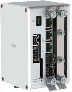
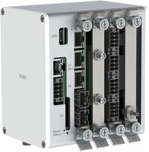

Materials Screws, washers, DIN rail locking pieceStainless steel AISI 316 Frame profile Aluminum EN AW 6060 T6 End covers Plastic PC/ABS
Damp heatIEC 60068 2 78+40 °C (+104 °F), 95 %RH Cold IEC 60068 2 1−60 °C (−76 °F)
(Vibrationsinusoidal) IEC 60068 2 65 … 13.2 Hz, 1 mm (0.04 in) amplitude 13.2 … 200 Hz, 0.7 g Rough handlingIEC 60068 2 31 MIL STD 810G, 516.6 Drop height 122 cm (48.03 in)
1)Operating temperature of some of the DMU801 plug in modules may be different. See the plug in module datasheets.
Technical data Operating environment Operating temperature 1) −40 … +80 °C (−40 … +176 °F)
Storage temperature −60 … +85 °C (−76 … +185 °F) Operating humidity 0 … 100 %RH, non condensing
Extended operating temperature (available on request) −60 … +80 °C (−76 … +176 °F)
Operating voltage 8 … 32 V DC (maximum 10 A) Power consumption, typical 500 mW Heating voltage 24 V DC nominal Maximum input current for heating12 A Mating connectors (power/heating input) 2 × Phoenix Contact FKCN 2,5/2 ST 5,08 (included) Inputs and outputs Ethernet Ports eth0 on CPU, additional ports with plug in modules Supported standard IEEE 802.3u Physical layer Base T Data rate 10/100 Mbps Connectors RJ45 with link LEDs Data transmission Full/Half duplex with auto negotiation USB Ports 1 Supported standard USB 2.0 Signaling High speed Connectors USB C Serial Ports •1 × RS 232 / RS 485 / SDI 12 port •2 × RS 485 ports •Additional ports with plug in modules Supported bit rate 1200 … 115 200 bps Power output 5 × software controllable power output pins
Compliance marksCE, RCM, UKCA
1)Modem Carrier Module DMX801 complies with EN 61326 1 basic level. Ethernet connection requires external surge protection to comply with EN 61326 1 industrial environment level. 187
1) Reserve some extra space for connectors and cables. For example, sensor connectors require a minimum of 20 mm (0.8 in) additional space from the DMU801 frame.
Processing system Processor ARM Cortex A9, 800 MHz Memory 1 GB DDR3L RAM, 8 GB eMMC Flash External memory SD card up to 32 GB 1) Operating system Linux Communications protocol IPv4 and IPv6 Real-time clock (standard) Accuracy Better than 20 s/month Backup battery CR1225/BR1225 Backup time Minimum 5 years 1)SD card available as accessory. Mechanical specifications Weight 2 slot unit: 0.35 kg (0.77 lb) 4 slot unit: 0.48 kg (1.06 lb) 8 slot unit: 0.71 kg (1.57 lb) Mounting DIN rail 35 mm (1.4 in) Dimensions (H × W × D) 1) 2 slots 120 × 77 × 84 mm (4.72 × 3.03 × 3.31 in) 4 slots 120 × 113 × 84 mm (4.72 × 4.45 × 3.31 in) 8 slots 120 × 185 × 84 mm (4.72 × 7.28 × 3.31 in)
Shock IEC 60068 2 27 MIL STD 202G, 213B 15 g, 11 ms, saw tooth 30 g, 11 ms, half sine Dry heat IEC 60068 2 2+85 °C (+185 °F)
Powering specifications
Signals •RS 232: RXD, TXD •RS 485: D+/D− Digital I/O 4 × 3.3 V logic level GPIO pins, pulse count/frequency capable Mating connectors • 2 × Phoenix Contact DFMC 1,5/4 ST 3,5 LR (included) •1 × M8 4 pin male TCP/IP Supported protocols DHCP, DNS, NTP, ARP, ICMP Echo, TCP/IP, SSH, UDP, DTLS, HTTPS 1) 1)The list is subject to change.
Compliance EU directives and regulations EMC, RoHS EMC immunityEN 61326 1, environmentindustrial 1) EMC emissionsCISPR 32 / EN 55032, Class B Maritime IEC 60945
• 1
Note: For more detailed information on the plug in modules, see the separate plug in module datasheets.
in modules Analog Measurement Module
•2protection:×standard
Serial
•1
•2
Modem
• SIM
Plug DMA801 × differential analog inputs with single ended measurement channels excitation power Module DMS801 × serial ports with power control and 485 ports × multipurpose RS 485 / RS 232 / SDI 12 port Module DMS802 × serial ports with power control and RS 232 serial ports × multipurpose RS 485 / RS 232 port × multipurpose RS 485 / RS 232 / SDI 12 port
Barometer
Serial
•4
•4
•1
•3protection:×isolatedRS
•Sensor
Self-diagnostics features Internal temperature monitoring Voltage monitoring Current Enclosuremonitoringdoormonitoring (to detect if the door is open or closed) 120 [4.72] [3.31]84 mm[in] 113 [4.45] 77 185[3.03][7.28]DMU801-2 DMU801-8DMU801-4 DMU801 dimensions (all sizes) 188
•2protection×0…30 V
•4
Ethernet Switch Module DME801 × Gigabit copper ports × SFP fiber optic ports Carrier Module DMX801 for standard mPCIe card modems card holder or for low-power LTE Cat 1 modem modules Module DMB801 Class A calibrated barometer
•Support
•3
embedded SIM •Support
•Updating
•ForFeatures:maintenance
Web
•
•Setting
Vaisala DMU801 Configuration Tool
parameters •Viewing
The configuration tool allows creating and modifying configuration files which define how a specific weather station works. Basic meteorological calculations are included, and they are easily extendable with existing Python modules as well as custom Python calculations. The configuration is visualized as colored nodes in the tool. and modifying configuration files Configuration files consist of scripts and libraries based on Python 3 basic meteorological calculations extendable with existing Python modules and custom Python calculations User Interface
•Easily
•Viewing
remotely www.vaisala.com 189
Software tools
•ForFeatures:creating
•No
•Includes
The web user interface allows setting station-specific parameters such as date and time. No separate installation is needed, but a browser connection is automatically established when the user connects to the station. The tool helps perform typical maintenance tasks, for example, enabling and disabling individual sensors and viewing or downloading log files. tasks dedicated software required station events, downloading log files and modifying station station metadata like power consumption details firmware
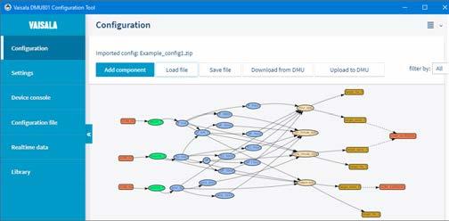
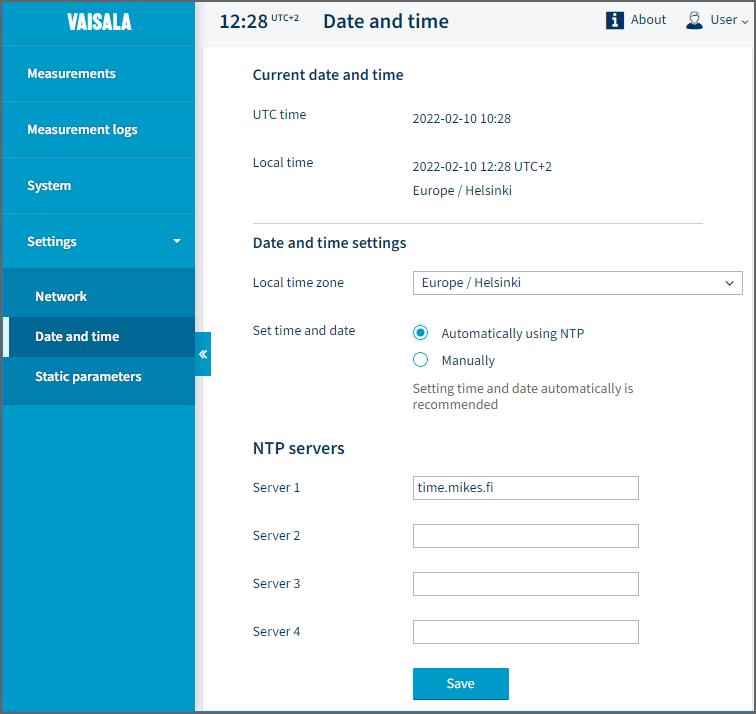
For serial sensor interfaces
Vaisala Serial Module DMS802 provides interfaces for serial sensors. With 2 standard RS 232 ports and 2 different multipurpose ports, each DMS802 allows connecting 4 additional sensors to Vaisala Data Management Unit DMU801. Depending on the size of your DMU801 base unit, you can connect up to 8 DMS802 serial modules to the system. Rugged solution with internal protection DMS802 operates in a wide temperature range and withstands fast temperature changes. Because of its internal rugged surge protection (up to 3 kA), external surge protection is not required.
Easy expansion when needed
DMS802 can be configured with the intuitive, node based Vaisala DMU801 Configuration Tool.
Features •Allows connecting additional sensors to Vaisala Data Management Unit DMU801 •Sophisticated, software controllable sensor power control •Heating power connection with overcurrent and surge protection (surge protectors on baseboard) •2 standard 3 wire RS 232 ports •1 multipurpose port that supports 2 wire RS 485 and RS 232 •1 multipurpose port that supports 2 wire RS 485, RS 232, and SDI 12 •Rugged lightning surge protection for all sensor connections
Vaisala Serial Module DMS802 extends the number of serial ports in Vaisala Data Management Unit DMU801. Each DMS802 provides interfaces for 4 serial connections. 190
DMS802 is easy to install during initial system setup and can also be plugged in later to expand the selection of sensors.
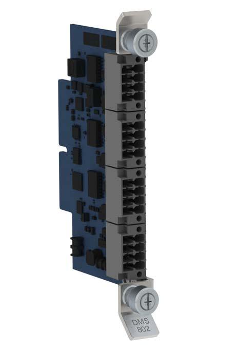
Technical data
Powering specifications Sensor supply voltage 3 … 26 V, software controllable Current limit 1.4 A −25 %/+20 % per port
Extended operating temperature (available on request) −60 … +85 °C (−76 … +185 °F)
Storage temperature −60 … +85 °C (−76 … +185 °F)
Operating environment Operating temperature −40 … +85 °C (−40 … +185 °F)
Inputs and outputs
Operating humidity 0 … 100 %RH, non condensing
Compliance marksCE, RCM, UKCA 1)Modem Carrier Module DMX801 complies with EN 61326 1 basic level. Ethernet connection requires external surge protection to comply with EN 61326 1 industrial environment level. www.vaisala.com 191
Dimensions (H x D) 123 × 79 mm (4.84 × 3.11 in) Distance between 2 plug in module slots in DMU801 frame 18 mm (0.71 in) Weight 65 g (2.3 oz)
Compliance EU directives and regulations EMC, RoHS EMC immunityEN 61326 1, environmentindustrial 1) EMC emissionsCISPR 32 / EN 55032, Class B Maritime IEC 60945 (Vibrationsinusoidal) IEC 60068 2 65 … 13.2 Hz, 1 mm (0.04 in) amplitude 13.2 … 200 Hz, 0.7 g Rough handlingIEC 60068 2 31 MIL STD 810G, 516.6 Drop height 122 cm (48.03 in) Shock IEC 60068 2 27 MIL STD 202G, 213B 15 g, 11 ms, saw tooth 30 g, 11 ms, half sine Dry heat IEC 60068 2 2+85 °C (+185 °F) Damp heatIEC 60068 2 78+40 °C (+104 °F), 95 %RH Cold IEC 60068 2 1−60 °C (−76 °F)
Material UL rated fire-resistive FR4 material Handles Stainless steel Coating Conformally coated against humidity
Mechanical specifications
Mating connectors 4 × Phoenix Contact DFMC 1,5/4 ST 3,5 LR (included) Supported bit rate 1200 ... 115 200 bps Power output Each serial port has a separate, software controllable power output pin Heating output Each serial port has separate heating power supply pins Signals, RS 232 RXD, TXD, GND Signals, RS 485 serial D+/D−
Ports •2 × standard RS 232 serial ports • 1 × multipurpose serial port supporting 2 wire RS 485 and RS 232 • 1 × multipurpose serial port supporting 2 wire RS 485, RS 232, and SDI 12
Easy expansion when needed DMS801 is easy to install during initial system setup and can also be plugged in later to expand the selection of sensors. DMS801 can be configured with the intuitive, node based Vaisala DMU801 Configuration Tool.
Features •Allows connecting additional sensors to Vaisala Data Management Unit DMU801 •Sophisticated, software controllable sensor power control •Heating power connection with overcurrent and surge protection (surge protectors on baseboard) •3 isolated RS 485 ports •1 multipurpose port that supports 2 wire RS 485, RS 232, and SDI 12 •Rugged lightning surge protection for all sensor connections
Vaisala Serial Module DMS801 provides interfaces for serial sensors. With 3 isolated RS 485 ports and 1 multipurpose port, each DMS801 allows connecting 4 additional sensors to Vaisala Data Management Unit DMU801. Depending on the size of your DMU801 base unit, you can connect up to 8 DMS801 serial modules to the system. Rugged solution with internal protection DMS801 operates in a wide temperature range and withstands fast temperature changes. Because of its internal rugged surge protection (up to 3 kA), external surge protection is not required.
Vaisala Serial Module DMS801 extends the number of serial ports in Vaisala Data Management Unit DMU801. Each DMS801 provides interfaces for 4 serial connections. 192
For serial sensor interfaces
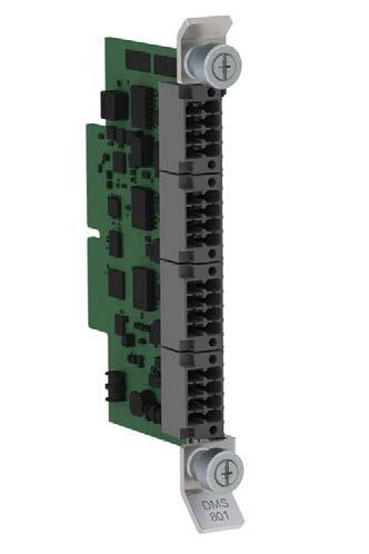
Compliance marksCE, RCM, UKCA www.vaisala.com
Technical data
Sensor supply voltage 3 … 26 V, software controllable Current limit 1.4 A −25 %/+20 % per port Mechanical specifications
Operating humidity 0 … 100 %RH, non condensing
Powering specifications
Damp heatIEC 60068 2 78+40 °C (+104 °F), 95 %RH Cold IEC 60068 2 1−60 °C (−76 °F)
Compliance EU directives and regulations EMC, RoHS EMC immunityEN 61326 1, environmentindustrial 1) EMC emissionsCISPR 32 / EN 55032, Class B Maritime IEC 60945 (Vibrationsinusoidal) IEC 60068 2 65 … 13.2 Hz, 1 mm (0.04 in) amplitude 13.2 … 200 Hz, 0.7 g Rough handlingIEC 60068 2 31 MIL STD 810G, 516.6 Drop height 122 cm (48.03 in) Shock IEC 60068 2 27 MIL STD 202G, 213B 15 g, 11 ms, saw tooth 30 g, 11 ms, half sine Dry heat IEC 60068 2 2+85 °C (+185 °F)
Inputs and outputs
193
Operating environment Operating temperature −40 … +85 °C (−40 … +185 °F)
Extended operating temperature (available on request) −60 … +85 °C (−76 … +185 °F)
Ports •3 × serial ports for isolated RS 485 • 1 × multipurpose serial port supporting 2 wire RS 485, RS 232, and SDI 12 Mating connectors 4 × Phoenix Contact DFMC 1,5/4 ST 3,5 LR (included)
Storage temperature −60 … +85 °C (−76 … +185 °F)
Supported bit rate 1200 … 115 200 bps Power output Each serial port has a separate, software controllable power output pin Heating output Each serial port has separate heating power supply pins Signals, RS 232 RXD, TXD, GND Signals, RS 485 serial D+/D− Signals, RS 485 serial, isolatedD+/D−
Dimensions (H x D) 123 × 79 mm (4.84 × 3.11 in)
Distance between 2 plug in module slots in DMU801 frame 18 mm (0.71 in) Weight 68 g (2.4 oz)
Material UL rated fire-resistive FR4 material Handles Stainless steel Coating Conformally coated against humidity
Many sensors for measuring temperature, pressure, and solar radiation have analog interfaces. DMA801 provides analog channels and converts the analog data into digital format for AnalogDMU801.inputs of DMA801 support Pt100, Pt1000, NTC thermistor, and voltage out sensors such as pyranometers. 4 ... 20 mA current loop measurement can be supported with an additional DCA420 adapter module or with external shunt resistor. Highly accurate DMA801 has unmatched accuracy and is thus well suited for various analog measurement applications.
Rugged solution with internal surge protection DMA801 operates in a wide temperature range and withstands fast temperature changes. Because of its internal rugged surge protection (up to 3 kA), external surge protection is not required.
Vaisala Analog Measurement Module DMA801 provides analog channels to Vaisala Data Management Unit DMU801. Each DMA801 includes 4 di erential analog channels and 2 additional single ended high voltage channels. Depending on the size of DMU801, it is possible to add up to 8 DMA801 modules to DMU801.
194
For analog sensor interfaces
Several DMA801 modules can be plugged into the same DMU801 base unit, if needed. DMA801 can be configured with the intuitive, node based Vaisala DMU801 Configuration Tool.
Features •Allows connecting analog sensors to Vaisala Data Management Unit •OneDMU801plug in module adds 4 differential analog inputs to the •Convertssystem analog signals into digital format with 24 bit •Rejectionresolutionfilter for 50/60 Hz •2frequencies×0...30V single ended measurement channel •Sophisticated, software controllable sensor power control •Heating power connection with overcurrent and surge protection (surge protectors on baseboard) •Rugged lightning surge protection for all sensor connections
Easy expansion when needed DMA801 is easy to install during initial system setup and can also be plugged in later to expand the selection of sensors.
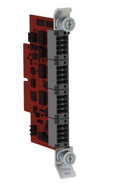
Powering specifications Sensor supply voltage 3 … 26 V, software controllable Current limit 0.7 A −25 %/+20 % per port
Heating output Each port has separate heating power supply pins
Uncertainty over temperature range −40 … +70 °C (−40 … +158 °F): ±2.5 V range < 0.05 % of reading ±1.85 μV ±1.25 V range < 0.04 % of reading ±2.3 μV ±620 mV range < 0.04 % of reading ±0.9 μV ±310 mV range < 0.04 % of reading ±0.75 μV ±156 mV range < 0.04 % of reading ±0.8 μV ±78 mV range < 0.04 % of reading ±1.25 μV ±39 mV range < 0.04 % of reading ±0.8 μV Uncertainty over temperature range −60 … +85 °C (−76 … +185 °F): ±2.5 V range < 0.05 % of reading ±1.85 μV ±1.25 V range < 0.04 % of reading ±2.3 μV ±620 mV range < 0.04 % of reading ±0.9 μV ±310 mV range < 0.04 % of reading ±0.85 μV ±156 mV range < 0.04 % of reading ±1.2 μV ±78 mV range < 0.05 % of reading ±1.25 μV ±39 mV range < 0.06 % of reading ±0.95 μV Common mode range +2.5 V / −0.9 V Voltage measurement 0 ... 30 V Uncertainty over temperature range −40 … +70 °C (−40 … +158 °F): To be Uncertaintydefinedover temperature range −60 … +85 °C (−76 … +185 °F): To be defined
Operating humidity 0 … 100 %RH, non condensing
Inputs and outputs Inputs •4 × differential analog inputs •2 × 0 … 30 V measurementsingle-endedchannels
Power output Each port has a separate, software controllable power output pin and a separate excitation pin
Distance between 2 plug in module slots in DMU801 frame 18 mm (0 71 in) Weight 64 g (2.26 oz)
195
Damp heatIEC 60068 2 78+40 °C (+104 °F), 95 %RH Cold IEC 60068 2 1−60 °C (−76 °F) Compliance marksCE, RCM, UKCA
Mating connectors 4 × Phoenix Contact DFMC 1,5/4 ST 3,5 LR (included)
1)Modem Carrier Module DMX801 complies with EN 61326 1 basic level. Ethernet connection requires external surge protection to comply with EN 61326 1 industrial environment level.
www.vaisala.com
Mechanical specifications
Dry heat IEC 60068 2 2+85 °C (+185 °F)
Operating environment Operating temperature −40 … +85 °C (−40 … +185 °F)
Dimensions (H x D) 123 × 79 mm (4.84 × 3.11 in)
Extended operating temperature (available on request) −60 … +85 °C (−76 … +185 °F) Storage temperature −60 … +85 °C (−76 … +185 °F)
Material UL rated fire-resistive FR4 material Handles Stainless steel Coating Conformally coated against humidity Compliance EU directives and regulations EMC, RoHS EMC immunityEN 61326 1, environmentindustrial 1) EMC emissionsCISPR 32 / EN 55032, Class B Maritime IEC 60945 (Vibrationsinusoidal) IEC 60068 2 65 … 13.2 Hz, 1 mm (0.04 in) amplitude 13.2 … 200 Hz, 0.7 g
Shock IEC 60068 2 27 MIL STD 202G, 213B 15 g, 11 ms, saw tooth 30 g, 11 ms, half sine
Rough handlingIEC 60068 2 31 MIL STD 810G, 516.6 Drop height 122 cm (48.03 in)
1) Verified by measuring ± 20 °C from ambient temperature, while ambient temperature spreads across the entire range. 2) Verified with DMU801 at 0 °C (+32 °F).
Technical data Accuracy specifications Temperature measurement (Pt100 sensor) 1) Measurement range −60 … +85 °C (−76 … +185 °F) Maximum error over −40 … +70 °C (−40 … +158 °F) < ±0.03 °C Maximum error over −60 … +85 °C (−76 … +185 °F) < ±0.04 °C Maximum error at 0 °C (+32 °F) 2) < ±0.01 °C Voltage measurement
A/D conversion Low noise 24 bit A/D converter with internal diagnostics
DMX801 Modem Carrier Module
• Provides interface for external modem through USB connection
Ordering options
•Supports standard mPCIe card modems
•Can be used for connecting any 2FF (mini) card to DMU801 included as an option
Features
•Supports low power LTE Cat 4 modem modules
Support for modems
DMX801 modem carrier module provides an interface for connecting a cellular modem to DMU801 data management unit. DMX801 supports standard mini Peripheral Component Interconnect express (mPCIe) card modems and low power LTE Cat 4 modem modules. DMX801 can be used as a SIM card carrier for any compatible 2FF (mini) card. It can also act as an interface for external modem using USB connection.
Vaisala Modem Carrier Module DMX801 is an interface module for connecting a mPCIe card modem or external modem through USB to Vaisala Data Management Unit DMU801. 196
You can order DMX801 with an integrated modem module or connect an external modem to it with USB. It is also possible to order DMX801 without integrated or external modem and provide your own integrated modem module instead, if that serves your purpose. Integrated modem modules provided with DMX801 by Vaisala have the required approvals in place and they are also tested to be compatible with DMU801 specifications. For your own integrated modem module, verify the compatibility before use. Easy expansion when needed DMX801 is easy to install during initial system setup but it can also be plugged in later. DMX801 can be configured with the intuitive, node-based Vaisala DMU801 Configuration Tool.
•Modem
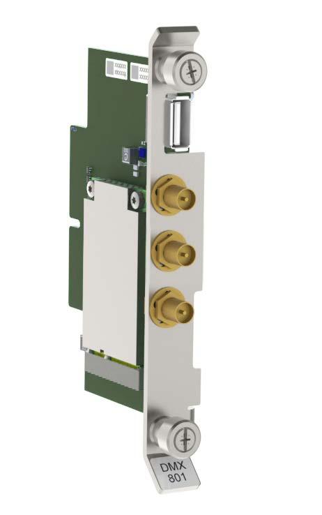
Type Full-Mini Card Dimensions (L × D × W) 56 × 30 × 5 mm (2.20 × 1.18 × 0.20 in) Max. (peak) current consumption2.75 A Supported voltage + 3.3 V Supported modem modules Model Quectel EG25 G LTE Cat4 Mini PCIe 1)
Shock IEC 60068 2 27 MIL STD 202G, 213B 15 g, 11 ms, saw tooth 30 g, 11 ms, half sine Dry heat IEC 60068 2 2+85 °C (+185 °F) Damp heatIEC 60068 2 78+40 °C (+104 °F), 95 %RH Cold IEC 60068 2 1−60 °C (−76 °F)
1)For more information, see the manufacturer documentation. Mechanical specifications
1)According to modem module specifications
Technical data Operating environment Operating temperature 1) −40 … +80 °C (−40 … +176 °F) Storage temperature −60 … +85 °C (−76 … +185 °F)
Dimensions (H × D) 123 × 79 mm (4.84 × 3.11 in) Distance between 2 plug in module slots in DMU801 frame 18 mm (0.71 in)
Weight, no modem included 64 g (2.26 oz)
Inputs and outputs Main antenna SMA female connector Antenna diversity SMA female connector GPS antenna SMA female connector USB connection Supported standard 2.0 Connector USB A mPCIe card specifications
Weight with EG25-G mPCIe modem, 3 × antenna connectors, and SIM card 86 g (3.03 oz)
Operating humidity 0 … 100 %RH, non condensing
Materials UL rated fire-resistive FR4 material Handles Stainless steel Coating Conformally coated against humidity Compliance EU directives and regulations EMC, RoHS EMC immunity EN 61326 1 EMC emissionsCISPR 32 / EN 55032, Class B Maritime IEC 60945
www.vaisala.com 197
1)For more information, see the manufacturer documentation. Supported external modems Model Cinterion PLS62T W USB 1)
Compliance marksCE, RCM, UKCA
Vibration(sinusoidal) IEC 60068 2 65 … 13.2 Hz, 1 mm (0.04 in) amplitude 13.2 … 200 Hz, 0.7 g Rough handlingIEC 60068 2 31 MIL STD 810G, 516.6 Drop height 122 cm (48.03 in)
•5 Gigabit Ethernet connectors including:•3copper port connectors
Adding Ethernet connectivity to DMU801
While the DMU801 base unit already includes a 100 MB Ethernet port for basic activities and a USB port for setup and maintenance tasks, DME801 adds 5 ports with 1 GB connections and expands the selection of supported Ethernet protocols.
Easy expansion when needed DME801 is easy to install during initial system setup and can also be plugged in later to expand the selection of sensors. DME801 can be configured with the intuitive, node-based Vaisala DMU801 Configuration Tool.
Vaisala Ethernet Switch Module DME801 adds 5 Ethernet connections to Vaisala Data Management Unit DMU801. Its 1 Gb Ethernet connectors include 3 copper ports and 2 SFP ports for fiber optic traffic. 198
Features
•2 small form-factor pluggable (SFP) module slots for fiber optic tra c
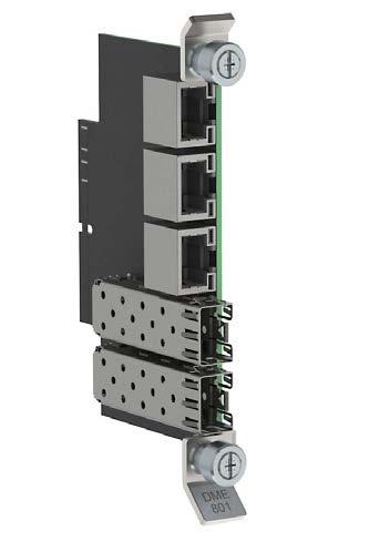
Dimensions (H × D) 123 × 79 mm (4.84 × 3.11 in) Distance between 2 plug in module slots in DMU801 frame 18 mm (0.71 in) Weight 65 g (2.3 oz) Material UL rated fire resistive FR4 material Handles Stainless steel Coating Conformally coated against humidity
Compliance EU directives and regulations EMC, RoHS EMC immunityEN 61326 1, environmentindustrial 1)
Operating humidity 0 … 100 %RH, non condensing
EMC emissionsCISPR 32 / EN 55032, Class B Maritime IEC 60945 (Vibrationsinusoidal) IEC 60068 2 65 … 13.2 Hz, 1 mm (0.04 in) amplitude 13.2 … 200 Hz, 0.7 g Rough handlingIEC 60068 2 31 MIL STD 810G, 516.6 Drop height 122 cm (48.03 in) Shock IEC 60068 2 27 MIL STD 202G, 213B 15 g, 11 ms, saw tooth 30 g, 11 ms, half sine Dry heat IEC 60068 2 2+85 °C (+185 °F) Damp heatIEC 60068 2 78+40 °C (+104 °F), 95 %RH Cold IEC 60068 2 1−60 °C (−76 °F)
Technical data
Extended operating temperature (available on request) −60 … +85 °C (−76 … +185 °F)
Compliance marksCE, RCM, UKCA
1)Ethernet connection requires external surge protection to meet EN 61326 1 industrial environment level. www.vaisala.com 199
Mechanical specifications
Operating environment Operating temperature −40 … +85 °C (−40 … +185 °F)
Storage temperature −60 … +85 °C (−76 … +185 °F)
Inputs and outputs Ports •3 × copper ports, RJ45 connectors • 2 × SFP module slots Supported standard IEEE 802.3 Physical layer, copper ports Base T Data rate 10/100/1000 Mbps Data transmission Full/Half duplex with autonegotiation
Accuracy with BAROCAP
and long-term stability •Wide operating
The Vaisala BAROCAP Pressure Module (BARO 1) has excellent accuracy, repeatibility and long-term stability over a wide range of operating temperatures. The pressure module is available with Class A factory calibration. The total accuracy with factory calibration is ± 0.15 hPa. The pressure module is well suited for demanding synoptic applications. The fine adjustment and calibration of the sensor are handled using the electronic working standards, which are traceable to international standards (NIST). The pressure module can be calibrated independently of DMB801 Themodule.observation range of DMB801 module is 500 ... 1100 hPa and its accuracy is ±0.05 hPa. Easy expansion when needed DMB801 is easy to install during initial system setup and can also be plugged in later. DMB801 can be configured with the intuitive, node-based Vaisala DMU801 Configuration Tool.
•Calibrationrange
Vaisala Barometer Module DMB801 includes a Class A calibrated barometer. It is designed to be used with Vaisala Data Management Unit DMU801.
•Accuracy
200
DMB801 Barometer Module repeatability, temperature traceable to international standards (NIST) ±0.05 hPa Class A barometer DMB801 uses the capacitive Vaisala BAROCAP sensor and features barometric pressure measurement for DMU801 calculation and additional pressure calculations (HCP, QFE, and QNH). The module includes a selfdiagnostics feature.
Features •Includes a Class A calibrated •Usesbarometertheproven Vaisala BAROCAPâ sensor •Excellent accuracy,
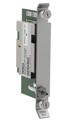
Material UL rated fire-resistive FR4 material Handles Stainless steel Coating Conformally coated against humidity Compliance
Measurement performance
Dimensions (H × D) 123 × 79 mm (4.84 × 3.11 in) Distance between 2 plug in module slots in DMU801 frame 18 mm (0.71 in) Weight 88 g (3.1 oz)
BARO 1 specifications Sensor type Vaisala BAROCAPâ (silicon capacitive) Observation range 500 … 1100 hPa Resolution 0.01 hPa Operating temperature −40 … +60 °C (−40 … +140 °F)
Extended operating temperature (available on request) 1) −60 … +85 °C (−76 … +185 °F)
Storage temperature −60 ... +85 °C (−76 ...+185 °F) Operating humidity 0 ... 100 %RH, non-condensing
EU directives and regulations EMC, RoHS EMC immunity EN 61326 1, environmentindustrial 1) EMC emissionsCISPR 32 / EN 55032, Class B Maritime IEC 60945 (Vibrationsinusoidal) IEC 60068 2 65 … 13.2 Hz, 1 mm (0.04 in) amplitude 13.2 … 200 Hz, 0.7 g Rough handlingIEC 60068 2 31 MIL STD 810G, 516.6 Drop height 122 cm (48.03 in) Shock IEC 60068 2 27 MIL STD 202G, 213B 15 g, 11 ms, saw tooth 30 g, 11 ms, half sine Dry heat IEC 60068 2 2+85 °C (+185 °F) Damp heatIEC 60068 2 78+40 °C (+104 °F), 95 %RH Cold IEC 60068 2 1−60 °C (−76 °F) Compliance marksCE, RCM, UKCA
Technical data Operating environment Operating temperature −40 … +60 °C (−40 … +140 °F)
Pressure range 500 … 1100 hPa Accuracy Class A Linearity 1) ±0.05 hPa Hysteresis 1) ±0.03 hPa Repeatability 1) ±0.03 hPa Calibration uncertainty 2) ±0.07 hPa Accuracy at +20 °C (+68 °F) 3) ±0.10 hPa Total accuracy at -40 … +60 °C (-40 … +140 °F) ±0.15 hPa Temperature dependence 4) ± 0.10 hPa Long-term stability ± 0.10 hPa/year 1) Defined as ±2 standard deviation limits of endpoint non-linearity hysteresis error, or repeatability error. 2) Defined as ± 2 standard deviation limits of inaccuracy of the working standard including traceability to NIST. 3) Defined as the root sum of the squares (RSS) of endpoint non-linearity, hysteresis error, repeatability error and calibration uncertainty at room temperature. 4) Defined as ±2 standard deviation limits of temperature dependence over the operating temperature range.
Mechanical specifications
1)Modem Carrier Module DMX801 complies with EN 61326 1 basic level. Ethernet connection requires external surge protection to comply with EN 61326 1 industrial environment level. www.vaisala.com 201
1)Measurement performance specifications not valid outside normal operating temperature range.
An all-in-one solution with many applications Vaisala Automatic Weather Station AWS310 is a weather data collection system that automatically measures, processes, and stores meteorological data for professional use. AWS310 can be operated as a standalone unit, or it can be connected with other compatible Vaisala weather stations to form weather observation networks. AWS310 stations can be used for several applications, such as synoptic, aviation, and agricultural meteorology, hydrology, and climatology. Using the same standard hardware and software for many purposes lowers the cost of training, spare parts, and logistics support.
AWS310 Automatic Weather Station Features •Complete solution for weather data •Commoncollectionoptions preconfigured, fully customizable for special •WMOneeds compliant sensors for validated data •Remote •Easymanagementconfigurationremotemonitoring of network status using the optional •LongNM10calibration intervals •Fast delivery for preconfigured systems
Validated data from reliable sensors Vaisala weather stations and instruments are fully compliant with World Meteorological Organization guidelines. The design quality of Vaisala weather stations has been proven with extensive tests in the development phase and on the field. To ensure continuous accuracy of measurements and calculations, AWS310 includes built-in data quality controls that test sensor data against minimum and maximum limits and changes between successive measurements. The weather station’s QML data logger continuously monitors the status of the sensors to ensure measurement reliability, notifying the user if the status of any sensor becomes invalid. All the sensors operate independently from each other, meaning that an individual sensor failure does not affect the performance of the other sensors. Maintenance made easier For AWS310 networks, the Vaisala Observation Network Manager NM10 software provides a powerful browserbased interface for 24/7 monitoring, access, and control of all your observation sites. Continuous, reliable observations improve the performance of your weather services and weathercritical operations, while shorter site visits and correct maintenance actions save time and money. Even without the optional NM10 software, it is possible to adjust settings and fix problems remotely. The Vaisala AWS Client software, that is included in each AWS310 delivery, supports setup, diagnostics, and data retrieval. The AWS310 StationView GUI allows the user to view basic station information, sensor status, and readings, to set site-specific parameters, and to perform many other functions using a graphical user AWS310interface.can also automatically download a new configuration file from a network server, making maintenance even easier.
Vaisala Automatic Weather Station AWS310 has everything that you need for taking accurate and reliable weather measurements. It is a complete communication and data monitoring solution including sensors, electronics, mast, and power supply.
202
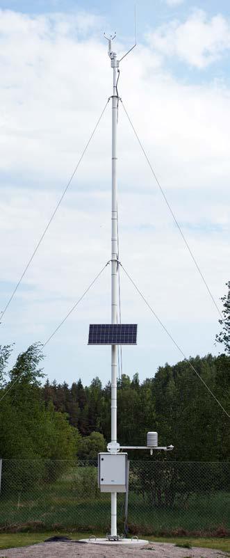
Vibration (sinusoidal)IEC 60068 2 6Frequency range 5 … 200 Hz 1.2 mm/s velocity, 5 … 12 Hz 0.7 g, 12 … 200 Hz Shock IEC 60068 2 275.0 g, pulse duration 11 ms with 100 pulses in each direction Damp heat, cyclicIEC 60068 2 30+40 °C (+104 °F) / 85 … 95 %RH Vibration (random)IEC 60068 2 645 … 100 Hz Storage Cold IEC 60068 2 1−60 °C (−76 °F) Dry heat IEC 60068 2 2+70 °C (+158 °F)
Extended operating temperature (project delivery) −60 … +50 °C (−76 … +122 °F), cold start at −40 °C (−40 °F) Storage temperature 2) −60 … +70 °C (−76 … +158 °F) Operating humidity 0 … 100 %RH Pollution degree 2 Maximum operating altitude 3000 m (approx. 9800 ft)
Environmental compliance Test Applied standard or test procedure Specification Operation Cold IEC 60068 2 1−40 °C (−40 °F) Dry heat IEC 60068 2 2+60 °C (+140 °F)
1)Excluding backup battery, QMD202, QST102 3, cellular modem, QMN101, RG13(H), SR50A, and PAA 36 X W. See the manufacturer documentation. 2)Excluding cellular modem, HMP155, and HMP110. See the manufacturer documentation.
Damp heat, cyclicIEC 60068 2 30+40 °C (+104 °F) / 85 … 95 %RH Transport Shock IEC 60068 2 2718 g, pulse duration 6 ms, with 100 pulses in each direction Rough handlingIEC 60068 2 31 Drop height 60 cm (23.62 in)
Compliance EU directives and regulations Low Voltage Directive (2014/35/EU) EMC Directive (2014/30/EU) RoHS Directive (2011/65/EU) amended by 2015/863
Operating environment Operating environment Outdoor use Use in wet location Yes Operating temperature 1) −40 … +60 °C (−40 … +140 °F)
Vibration (random)IEC 60068 2 645 … 200 Hz EMC compliance Test Applied standard or test procedure Specification
IP rating IP66 NEMA rating NEMA 4X Maximum operating wind speed75 m/s (168 mph) Door opening angle 100° Material Stainless steel AISI 316, painted white Size (enclosure only) 600 × 500 × 207 mm (23.62 × 19.68 × 8.15 in)
Weight (excluding backup battery) < 30 kg (66 lb) 1) 203
Technical data
EMC compatibility EN 61326 1, industrial environment FCC part 15, class B ICES 3 (B) Electrical safety EN 61010 1 Compliance marks CE, FCC, ICES, RCM
Powering specifications AC (mains) power 100 … 240 V AC, ±10 % 50 … 60 Hz 5.6 A maximum (120 V AC) Mains fuse (nominal) 10 A External DC 16.8 … 26.4 V DC 10 A maximum Solar panel 70 W 15.5 … 30 V DC 2.5 A maximum Internal backup battery 12 V / 26 Ah or 12 V / 52 Ah Backup battery fuse 10 A Overvoltage category II ENC652 specifications Approvals UL 50 / UL 50E-listing
Emissions radiatedCISPR 32 / EN 55032, Class B 30 MHz … 2 GHz Emissions conducted to mains (AC) CISPR 32 / EN 55032, Class B 150 kHz … 30 MHz Emissions conducted to linestelecommunication CISPR 32 / EN 55032, Class B 150 kHz … 30 MHz Emissions, harmonic current EN 61000 3 20 … 40th harmonic Immunity to RF field (80 MHz … 6 GHz) EN 61000 4 311 V/m (80 MHz … 1 GHz) 4 V/m (1 GHz … 6 GHz) Immunity to electrical fast transient EN 61000 4 4 2 kV AC, 1 kV I/O Immunity to surgeEN 61000 4 52 kV / 1 kV AC, 1 kV I/O Immunity conductedtoRF EN 61000 4 64 V e.m.f. (150 kHz … 80 MHz) Immunity to voltage dips and interruptsshort IEC 61000 4 110 % 1 cycle 40 % 10 cycles 70 % 25 cycles 0 % 250 cycles
Maintenance terminal softwareVaisala AWS Client with StationView GUI For other data validation, calculation, report, mast, powering, sensor, communication data collection software options, and measurement unit conversions, contact Vaisala.
Weather transmitter WXT531, WXT532, WXT535, WXT536
Global solar radiation SMP3, SMP6, SMP10, SMP21, SMP22, SP Lite2 Net radiation QMN101 UV radiation SUV5
Wind speed and direction WMT700, WA15 (dual sensors available)
Air temperature, relative humidity, and dew point HMP110, HMP155
Standard sensor options
Visibility and present weatherPWD22 Cloud height and sky conditionCL31 Ground temperature QMT110 Snow depth SR50A Water level VEGAPULS 61, PAA 36 X W
Standard accessories USB maintenance cable Removable 2 GB CF memory card www.vaisala.com
Wireless communication 4G LTE cellular modem with seamless fallback to 2G and 3G networks
Standard communication options
Satellite communication Vaisala GOES DCP Transmitter QST102 3
Athmospheric pressure BARO 1 (Class A accuracy), PTB330 (Class A accuracy, with 3 transducers)
Five-band 3G cellular modem (with quad-band GSM GPRS support)
Rain/Precipitation RG13(H), OTT Pluvio2 L
Landline communication RS 232, RS 485, LAN Data collection software Vaisala Observation Network Manager NM10
204
Data collection Meteorological data is sent to the airport weather observation system in real time. There are several standard communication options available, including landline communication through RS 232, RS 485, or leased-line modem, or wireless communication through a UHF/VHF radio interface. To provide redundancy in safety-critical airport applications, data can be sent simultaneously via 2 parallel communication ports. The data is also saved on the weather station’s external memory card. The stored log files can be exported to external applications.
AWS310‑SITE Automatic Weather Station Features •Designed and tested for aviation applications with Vaisala AviMetâ •Csystemsomplete solution for weather data •Widecollectionrangeofinstallation, power supply, and communication •ICAO-optionsand WMO-compliant sensors with long calibration •Surgeintervalsprotection for power input, sensor connections, and output data connections
Vaisala Automatic Weather Station AWS310 SITE is an automatic weather station that is optimized for airport weather observations. Based on the proven Vaisala AWS310 weather station, AWS310 SITE provides reliable and accurate weather measurements for aviation applications using ICAO and WMO-compliant sensors.
Standard safety features
205
Optimized for airport weather observation needs AWS310 SITE is specially designed and tested for Vaisala AviMet Automated Weather Observing System (AWOS) and Low level Windshear Alert System (LLWAS), ensuring complete end to end system integration. With Vaisala AviMet, users are able to collect and view weather data remotely, as well as monitor and control the AWS310 SITE observation stations. A complete solution
Excellent long-term stability
Sensor calibration is vital to accurate and reliable observations. The sensors of AWS310 SITE ensure excellent long-term stability with a low risk of drift or sudden changes in calibration. This results in longer calibration intervals, lower maintenance costs, and reduced downtime. Installation options
The AWS310 SITE solution includes everything required for accurate and reliable weather measurements: the enclosure, a wide variety of sensor options, installation kits, power supply, and communication devices. The solution has a robust, tightly sealed IP66 stainless steel (AISI 316) enclosure to protect the electronics. AWS310 SITE is available with different installation and powering options according to customer needs and site requirements, including a solar-powered option for remote Thelocations.AWSClient software is included for maintenance purposes to support setup, diagnostics, and data retrieval.
There are several standard masts and mast installation kits available for AWS310 SITE. Frangible options include pole masts DKE110F, DKP721, and DKP711 and lattice mast DKE200. Vaisala frangible masts are impact-tested, and they comply with the frangibility requirements set in the following •specifications: ICAO Doc 9157 Aerodrome Design Manual, Part 6 Frangibility, First Edition, 2006 • FAA AC 150/5345 45C – Low Impact Resistant Structures, 2007
AWS310 SITE includes surge protection for the power input, sensor connections, and output data connections. Surge protectors protect the AWS310 SITE unit from potential damage caused by poor or variable power quality, or other possible surges.
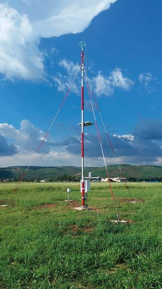
Standard accessories 2 enclosure locks USB maintenance cable 2 removable 2 GB CF memory cards
www.vaisala.com 206
Operating humidity 0 … 100 %RH Pollution degree 2 Maximum operating altitude 3000 m (approx. 9800 ft)
Emissions radiatedCISPR 32 / EN 55032, Class B 30 MHz … 2 GHz Emissions conducted to mains (AC) CISPR 32 / EN 55032, Class B 150 kHz … 30 MHz Emissions conducted to linestelecommunication CISPR 32 / EN 55032, Class B 150 kHz … 30 MHz Emissions, harmonic current EN 61000 3 20 … 40th harmonic Immunity to RF field (80 MHz … 6 GHz) EN 61000 4 311 V/m (80 MHz … 1 GHz) 4 V/m (1 GHz … 6 GHz)
Vibration (random)IEC 60068 2 645 … 200 Hz
Extended operating temperature (with insulated enclosure and heating) −60 … +50 °C (−76 … +122 °F), cold start at −40 °C (−40 °F)
Operating environment
1)Excluding backup battery, QMD202, DXL421, and RG13(H). See the manufacturer documentation.
Global solar radiation SMP3, SMP6, SMP10
Solar panel 70 15.5W… 30 V DC 2.5 A maximum Internal backup battery 12 V / 26 Ah or 12 V / 52 Ah Backup battery fuse 10 A Overvoltage category II ENC652 specifications Approvals UL 50 / UL 50E-listing
Immunity to electrical fast transient EN 61000 4 42 kV AC, 1 kV I/O Immunity to surgeEN 61000 4 52 kV / 1 kV AC, 1 kV I/O Immunity conductedtoRF EN 61000 4 64 V e.m.f. (150 kHz … 80 MHz)
Soil temperature QMT110 Standard interface CL31, LT31, FS11, FS11P, PWD22, TSS928
Dual communication Any combination of 2 standard communication options
Environmental compliance Test Applied standard or test procedure
Vibration (sinusoidal)IEC 60068 2 6Frequency range 5 … 200 Hz 1.2 mm/s velocity, 5 … 12 Hz 0.7 g, 12 … 200 Hz Shock IEC 60068 2 275.0 g, pulse duration 11 ms with 100 pulses in each direction Damp heat, cyclicIEC 60068 2 30+40 °C (+104 °F) / 85 … 95 %RH
IP rating IP66 NEMA rating NEMA 4X Maximum operating wind speed75 m/s (168 mph) Door opening angle 100° Material Stainless steel AISI 316, painted white Size (enclosure only) 600 × 500 × 207 mm (23.62 × 19.68 × 8.15 in)
Vibration (random)IEC 60068 2 645 … 100 Hz Storage Cold IEC 60068 2 1−60 °C (−76 °F) Dry heat IEC 60068 2 2+70 °C (+158 °F) Damp heat, cyclicIEC 60068 2 30+40 °C (+104 °F) / 85 … 95 %RH Transport Shock IEC 60068 2 2718 g, pulse duration 6 ms, with 100 pulses in each direction Rough handlingIEC 60068 2 31Drop height 60 cm (23.62 in)
Operation Cold IEC 60068 2 1−40 °C (−40 °F) Dry heat IEC 60068 2 2+60 °C (+140 °F)
Fiber optic communication With Vaisala Field Communication Box FOC201 or customer-provided solution
Sunshine duration CSD3 Rain/Precipitation RG13(H), OTT Pluvio2 L Runway temperature DRS511 Runway temperature and surface stateRWCC
EMC compliance Test Applied standard or test procedure Specification
AC (mains) power 100 … 240 V AC, ±10 % 50 … 60 Hz 5.6 A maximum (120 V AC) Mains fuse (nominal) 10 A External DC 16.8 … 26.4 V DC 10 A maximum
Technical Data
Storage temperature 2) −60 … +70 °C (−76 … +158 °F)
Air temperature and relative humidityHMP155 Barometric pressure PTB330 (Class A accuracy, with 3 transducers)
2)Excluding HMP155. See the manufacturer documentation.
Specification
Operating environment Outdoor use Use in wet location Yes Operating temperature 1) −40 … +60 °C (−40 … +140 °F)
Ground temperature QMT107
Weight (excluding backup battery) < 30 kg (66 lb) 1)
Landline communication RS 232, RS 485, or leased-line modem Wireless communication UHF/VHF radio interface
Powering specifications
Standard sensor options Wind speed and direction WMT700, WA15 (dual sensors available)
Immunity to voltage dips and interruptsshort IEC 61000 4 110 % 1 cycle 40 % 10 cycles 70 % 25 cycles 0 % 250 cycles
Standard communication options
A digital I/O unit adds 8 digital outputs and 8 digital inputs for sensors, power optimizing, and unmanned control functions based on user-defined requirements. 202 [7.96] 192 [7.56] [in]mm[3.75]95[2.32]59
Easy to use Sensor measurements, statistical calculations, data logging, and data transmissions are performed according to configuration done with the Vaisala Lizard Setup Software. The software has many setup options and advanced features. Easy to upgrade The system architecture enables QML201C to be easily upgraded with new sensors, calculations, output formats, and logging schedules at any time to accommodate the changing requirements of the users. The basic system provides RS 232, RS 485, and SDI 12 ports for interfacing with almost any type of telemetry, terminal, display, and smart sensor. With optional plug-in modules, the number of serial ports can be extended from 2 to up to 8 ports, enabling multiple RS 232, RS 485, SDI 12, and Ethernet connections. Easy to expand QML201C can also be expanded with another QML201C unit that offers 10 additional differential analog channels and serial lines.
Features •Easy to install, economical to maintain and upgrade •Field-proven reliability and accuracy in harsh environments •Low power consumption •Extensive calculation and data logging capability •Good expandability and high level of customization through open and modular design •Built in TCP/IP connectivity •Compact design
A 32 bit central processing unit (CPU), 24 bit A/D conversion (ADC), autocalibration of the ADC, and measurement electronics, coupled with advanced data quality control and validation software, ensure the accuracy of data measurement.
QML201C Data Logger
Vaisala Data Logger QML201C is built using proven sensor technology by Vaisala.
QML
data logger dimensions 207
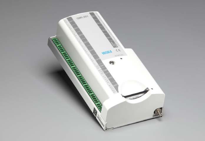
Serial Standard RS 232 2 wire RS 485 SDI 12 Optional 2 optional plug in slots for communication modules to increase the number of the serial I/O channels up to 8 pcs Fast serial expansion bus for connecting digital I/O module, for example Speed 300 … 38 400 bps
EMC emissions CISPR 32 / EN 55032, Class B Compliance marks CE, FCC, ICES, RCM
All data for ambient temperature range −50 … +60 °C (−58 … +140 °F) unless otherwise specified. Temperature measurement (Pt100 sensor)
Storage temperature −60 … +70 °C (−76 … +158 °F)
Uncertainty over −60 … +70 °C (−76 … +158 °F) < ±0.02 °C, typically Maximum error over −50 … +60 °C (−58 … +140 °F) < ±0.04 °C Maximum error over −60 … +70 °C (−76 … +158 °F) < ±0.08 °C Maximum error at 0 °C (+32 °F) 1) < ±0.02 °C Voltage measurement Uncertainty over temperature range −5 … +30 °C (14 … +86 °F): ±5 V range < 0.06 % of reading ±100 μV ±2.5 V range < 0.04 % of reading ±50 μV ±250 mV range < 0.06 % of reading ±6 μV ±25 mV range < 0.06 % of reading ±5 μV Uncertainty over temperature range −40 … +60 °C (−40… +140 °F): ±5 V range < 0.06 % of reading ±100 μV ±2.5 V range < 0.04 % of reading ±50 μV ±250 mV range < 0.15 % of reading ±15 μV ±25 mV range < 0.15 % of reading ±10 μV Uncertainty over temperature range −50 … +60 °C (−58 … +140 °F): ±5 V range < 0.08 % of reading ±100 μV ±2.5 V range < 0.08 % of reading ±50 μV ±250 mV range < 0.15 % of reading ±15 μV ±25 mV range < 0.15 % of reading ±10 μV Uncertainty over temperature range −60 … +70 °C (−76 … +158 °F): ±5 V range < 0.12 % of reading ±150 μV ±2.5 V range < 0.12 % of reading ±80 μV ±250 mV range < 0.20 % of reading ±20 μV ±25 mV range < 0.20 % of reading ±10 μV Common mode range +7 V / −3 V
Measurement range −60 … +70 °C (−76 … +158 °F)
Operating humidity 0 … 100 %RH Inputs and outputs Processor 33 MHz, 32 bit Motorola A/D conversion 24 bit Memory 2 MB RAM and 4 MB program Data logging memory 3.3 MB internal Flash memory External memory card capacity2 GB on CompactFlash card Sensor inputs 10 analog inputs (20 single-ended 2inputs)counter/frequency inputs Internal channel for pressure sensor BARO 1 External powering 8 … 30 V DC Power consumption < 10 mA / 12 V (typically with basic 5 sensors)
Configurable parameters Speed, start bits, data bits, stop bits, parity, XON/XOFF, and checksum Ethernet Standard IEEE 802.3 2 plug in slots for Ethernet modules DSE101 Speed 10 Mbps (10BASE T) Can also be connected to 100/1000 Mbps (100/1000BASE T) networks with 10 Mbps Parameters Full/Half duplex with autonegotiation TCP/IP Supported protocols ARP, UDP/IP, TCP/IP, FTP, SMTP, PPP (with PAP or CHAP authentication), HTTP (GET), Telnet, ICMP Echo, DHCP, NTP, DNS, serial port tunneling over TCP/IP
Real-time clock (standard)
Extended operating temperature−60 … +70 °C (−76 … +158 °F)
1) Verified with QML data logger at 0 °C (+32 °F).
Technical data
Operating environment
EMC immunity EN 61326 1, industrial environment FCC part 15, class B ICES 3 (B)
Compliance EU directives and regulations EMC Directive (2014/30/EU) RoHS Directive (2011/65/EU) amended by 2015/863
Operating temperature −50 … +60 °C (−58 … +140 °F)
www.vaisala.com 208
Accuracy specifications
Uncertainty over temperature range −60 … +70 °C (−76 … +158 °F): 20 Hz … 8000 Hz < 0.04 % of reading 8000 Hz … 20000 Hz < 0.40 % of reading
Backup time 5 years minimum with CR1220 battery
Accuracy Better than 20 s/month
Communication specifications
Frequency measurement
•Stand-alone
•LCD
QMD202 Fixed Display Features display with backlighting design allows installations up to 1000 meters (3280 ft) from the weather to
The QMD202 display includes a programmable LCD display with backlighting. Several lines of alphanumeric data can be shown. The full display size expressed in characters is 20 × 6 (width × height).
The displayed data is sent as reports to the display. The contents, format, and updating intervals of these reports are user-configurable. The update interval can be anything between 1 second and 24 hours. 209
•Easily
Local user interface for weather station
•Easystationway
Vaisala Fixed Display QMD202 provides the local user interface for viewing the values measured and calculated by the QML data logger, and for adding observations or reference data into the system.
•Freelymeasurementviewingvaluesconfigurablewith
The weather station can be equipped with the QMD202 display and keyboard unit at the installation site. The operator can use the display to view the measurement values locally and insert observations or reference data into the Thesystem.operator can use the Vaisala configuration software to configure up to 24 pages to the display. In addition, it is possible to create configuration views for adjusting station-specific settings and changing the offset and gain values of the sensors connected to the system. Installation inside enclosure
line •DIN
The QMD202 unit can be mounted on a DIN rail inside the weather station enclosure. The display can then be accessed only by opening the enclosure door, which can be firmly locked. Installation outside enclosure
•Data
•Communication
LCD display
Vaisala configuration software accessible keypad with user-friendly menu and system parameters can be entered using the keypad through SPI, RS 232, or RS 485 rail mounting
The QMD202 unit can also be installed outside the weather station enclosure using the RS 232 or the full-duplex RS 485 connection. The RS 485 connection together with a DSI485 module in the QML data logger allows installations up to 1000 meters (3280 feet) from the weather station.
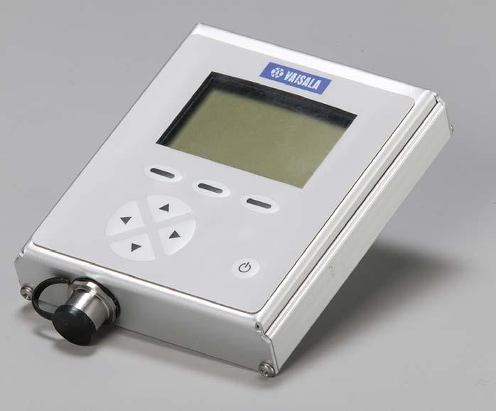
Technical data Operating environment Operating temperature 1) −20 … +60 °C (−4 … +140 °F) Survival temperature −40 … +60 °C (−40 … +140 °F) Storage temperature −60 … +60 °C (−76 … +140 °F)
Compliance EMC compatibility EN 61326 1, industrial environment Vibration IEC 60068 2 6, level 2 g Mechanical specifications Dimensions (H × W × D) 135 × 95 × 28 mm (5.31 × 3.74 × 1.11 in) Weight 0.23 kg (0.5 lb) Mounting DIN rail Enclosure material Aluminum LCD display size (W × H) 20 × 6 characters Example of QMD202 display www.vaisala.com 210
SPI Connected to and powered by QML data logger through 10 wire flat cable Maximum communication distance RS 485 1000 m (3280 ft) RS 232 30 m (98 ft 5 in) SPI Inside the weather station enclosure
Inputs and outputs Input voltage RS 232, RS 485 8 … 18 V DC SPI 3.3 and 5.0 V DC powered from QML data logger Power consumption RS 485 mode, backlight off 96 mW at 12 V RS 485 mode, backlight on 252 mW at 12 V RS 232 mode, backlight off 132 mW at 12 V RS 232 mode, backlight on 276 mW at 12 V SPI, backlight off 20 mW SPI, backlight on 85 mW Interface Connector for RS 232, RS 485, and power supply 8 pin M12 RS 485 Full duplex, non-isolated, 1200, 2400, 4800, 9600 bps (default 9600 bps) RS 232 1200, 2400, 4800, 9600 bps (default 9600 bps)
1)The LCD display does not show any characters in temperatures below −20 °C (−13 °F).
interface sensors •Industry
Features •All
All this comes in a 14 mm (0.55 in) wide package equipped with industry standard EN 60715 rail mount: 35 mm (1.38 in) DIN rail.
QSP431 Surge Protection Unit in one: protection for serial line and power lines in unit protection for serial standard EN 60715 rail mount
The Vaisala Surge Protection Unit
•Heavy-duty
In addition to protective functionality, QSP431 acts also as a connector unit between the weather station and the sensor cabling, eliminating no need for separate screw terminals.
QSP431 is suitable to be used in maritime applications with requirements for 500 V chassis isolation 1). Isolation is userselectable by removing a single chassis connection screw.
one
QSP431 provides effective protection for all lines connected to a serial sensor: both operating and heating voltage supplies and either RS 485 or RS 232 serial interface line.
Suitable for Maritime Use
1)In compliance with Lloyd’s Register (LR) Type Approval System, Test Specification Number 1; 2002, Performance and Environmental Test Specification for the Environmentally Tested Products used in Marine and Offshore Applications, and Det Norske Veritas Standard for Certification No. 2.4; Environmental Test Specification for instrumentation and Automation Equipment, April 2006 211
QSP431 is a compact device which provides heavy-duty protection for serial interface sensors. Surge Protector and Connector
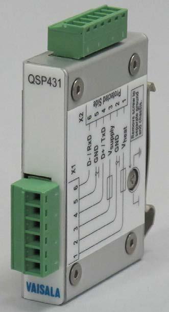
Screw terminal connectors 6 pins with detachable plugs (2 pcs), pitch 3.81 mm (0.15 in)
www.vaisala.com 212
Maximum current 3 A Maximum surge current (IEC 61000 4 5 8/20 µs pulse), common and differential modes 3 kA Mechanical specifications
Operating environment Operating temperature −40 … +60 °C (−40 … +140 °F) Storage temperature −60 … +70 °C (−76 … +158 °F)
Operating humidity 0 … 100 %RH
Dimensions (H × W × L) 74 × 14 × 62 mm (2.91 × 0.55 × 2.44 in)
Wire without collar, with ferrules0.25 … 1.5 mm² (24 … 16 AWG)
Technical data
Conductor cross-sections
Plain wire 0.14 … 1.5 mm² (26 … 16 AWG) Wire with plastic collar, with ferrules0.25 … 0.5 mm² (24 … 21 AWG)
Frame isolation (applicable only when chassis screw is removed) Nominal isolation voltage 500 V Insulation resistance > 10 MΩ Protection breakdown voltage700 V Compliance EU directives and regulations RoHS Directive (2011/65/EU) amended by 2015/863 Compliance marks CE
Inputs and outputs Signal line 2 lines (with common ground pin) Maximum data rate 57 600 bps Maximum voltage ±12 V DC Maximum current 750 mA Signal line series resistance 15 Ω Power line 2 lines (with common ground pin) Maximum voltage ±32 V DC
•High
•Complies
• Specifically
•Meets
Automatic
To obtain the most accurate true wind calculation, the ship's own gyrocompass and navigation system can be used to provide the required heading and ship speed, direction, and position information. However, an optional GPS compass can also be integrated into the Thesystem.system fully supports all the requirements for data communication as specified in NMEA 0183 and IEC 1162 1. When the system is equipped with several wind sensors, the built-in algorithm selects the most accurate wind data from these sensors.
AWS430 supports LAN connection with XML and Modbusâ TCP/IP protocols and remote maintenace functionality. Satellite communication options are also available. Self-diagnostics and constant data availability To ensure data quality, the built-in algorithms continuously monitor the sensor data, providing an immediate alert in case of a fault. For every parameter, the minimum and maximum readings as well as step limits are tested. Various parameters are also crosschecked. Designed for demanding maritime applications All the materials of AWS430 have been selected for their ability to withstand the harsh, corrosive conditions experienced in maritime environments. The station has successfully passed a wide variety of environmental, electrical, vibration, and shock tests. Test specifications comply with both the Lloyds' Register approval system and the IEC 60945 international maritime standard for applicable parts. 213
data •CompliescommunicationwithCAP
AWS430 contains either a waterproof outdoor enclosure with various mounting options or a 19" equipment rack unit. The outdoor enclosure is designed to withstand the corrosive conditions that prevail aboard ships and platforms as well as the freezing conditions experienced in extreme-weather environments. It is also able to endure vibration and shock. Wide range of high quality measurements AWS430 measures the following basic weather parameters: wind speed and direction (relative wind, true wind, upwind), atmospheric pressure, air temperature, and humidity. Additional sensors can be installed for measuring other parameters, including water temperature, duration of rain and sunshine, global and long wave radiation, amount of precipitation, cloud height, visibility, tide, wave height and direction, water level, ocean current speed and direction, and ship motion. AWS430 has built in calculation for many meteorological and statistical parameters such as dew point temperature. Flexible integration
data •Accuratevalidationtrue
AWS430 Weather Station Features designed for critical maritime weather applications anti-corrosive design with Lloyd’s Register and IEC 60945 requirements for applicable parts data availability test procedures and wind calculation even from multiple sensors NMEA 0183 and IEC 1162 1 requirements for 437, HCA, NORSOK, and BSL D5 1 requirements for offshore helicopter landing areas
Automatic Weather Station AWS430 provides reliable meteorological and oceanographic data in maritime environments. It is designed for maritime environments such as ports, ships, and o shore platforms.
•High-quality
•Built-in

Operating humidity 0 … 100 %RH, non-condensing IP rating IP66 Dimensions (H × W × D) 600 × 500 × 200 mm (23.62 × 19.69 × 7.87 in) Material Stainless steel (AISI316), painted white Weight Max. 40 kg (88.18 lb) Backup battery 12 V, 2.6 Ah 1)Power cold start −40 °C (−40 °F) 19" Rack Specifications
Options for Hazardous Areas Wind speed and direction Gill IS WindObserver Atmospheric pressure Keller PAA 33 X Ei Air temperature, relative humidity, and dew point HMT360 Wave height, direction, period, and tideRadac WG5 Ex Additional Options RS-485/RS-232 sensors SDI-12 AnalogEthernetsensorsdevicessensors,with differential measurement up to 10 sensors Digital sensors, 2 counter/frequency inputs Software-controlled power outputs
Communication Options
Powering Specifications
Operating temperature −50 … +60 °C (−58 … +140 °F) 1) Storage temperature −60 … +70 °C (−76 … +158 °F)
Operating temperature −25 … +60 °C (−13 …+140 °F) Storage temperature −60 … +70 °C (−76 …+158 °F)
Operating humidity 0 … 100 %RH, non-condensing IP rating IP21 Dimensions (H × W × D) 177 × 433 × 555 mm (6.97 × 17.05 × 21.85 in) Material Aluminum Weight Max. 15 kg (33.07 lbs) Backup battery 12 V, 2.6 Ah
Powering 100 … 240 VAC, 50 … 60 Hz 24 VDC (18 VDC ...30 VDC) 1) Internal battery 2.6 Ah / 12 V Battery regulator charge/recharge Temperaturecontrol compensation Deep discharge protection
Typical Options Wind speed and direction WMT700 Atmospheric pressure BARO-1, PTB330 Air temperature, relative humidity, and dew point HMP155 Rain/Precipitation RM Young 50202, RG13(H), DRD11A Water temperature DTS12W GPS satellite compass Vector G2 Visibility and present weatherPWD series Ceilometer CL31 Wave height, direction, period, and tideRadac WG5 series
Outdoor Enclosure Specifications
Technical data
Satellite communication Customer VSAT / Inmarsat-C through AWS430 LAN or serial port Wireless communication UHF, VHF, GSM, GPRS Landline communication RS-232, RS-485 bus, LAN, ModBus, TCP/IP, and serial Data displays Vaisala PC display software Vaisala Panel Displays 214
1)DC powering available only with the outdoor enclosure Data Validation, Calculations, and Reports Data quality control Upper/Lower climatological limits Step change validation Statistical calculations Averaging over user-set periods True and relative wind, wind selection (upwind) Message inputs NMEA 0183 HDT/RMC/VTG/GLL Message outputs NMEA 0183 MVW/XDR/MTW Vaisala SMSAWS XML Modbusformat â TCP/IP and serial Sensor Options
Current speed and direction Aanderaa 4830R, Nortek Aquadopp, Nortek AWAC Water salinity Aanderaa 4419R Water level Keller PAA 36 X W, VEGAPULS 61 and 62 Ship motion SMC IMU-108 Solar radiation / Sun duration Kipp & Zonen solar instruments
Electrical safety IEC/EN/UL/CSA 60950 1 EMC immunity IEC 61326 1 Industrial environment (EN 61326 1)
Vibration IEC 60068-2-6/IEC 60945 Shock MIL-STD-202G, Method 213B, cond. J Dry heat IEC 60068-2-2/IEC 60068-2-48 Damp heat Cyclic IEC 60068-2-30
Conducted LF immunity IEC 61000-4-16
Environmental and electrical specifications are valid only for the AWS430 main unit. For environmental and electrical specifications of the sensors, see the sensor specifications. www.vaisala.com 215
Compliance For applicable parts, AWS430 main unit is in compliance with the following:
Extreme conditions, outdoor enclosureIEC 60068-2-3
Wind driven rain, outdoor enclosureMIL–STD–810G, method 506.5 Corrosion and salt mist, outdoor enclosure IEC60068-2-52, VDA 621-415
•Lloyd’s Register (LR) Type Approval System, Test Specification Number 1: 2002, Performance and Environmental Test Specification for the Environmentally Tested Products used in Marine and Offshore
Dielectric tests IEC 60947-2
Emissions, outdoor enclosure CISPR22 Class B (EN 55022) Emissions, rack enclosure CISPR32 Class B (EN 55032) RF field immunity IEC 61000-4-3 Insulation resistance IEC 60092-504
Power supply short term variation immunity IEC 61000-4-11 Power supply failure immunityIEC 61000-4-11/IEC 60092-504
•IECApplications60945International Standard, 4th edition, 2002-08, Maritime Navigation and Radio communication Equipment and Systems - General Requirements Methods of Testing and Required Test Results
Low temperature, outdoor enclosureIEC 60068-2-1
Conducted RF immunity IEC 61000-4-6 EFT immunity IEC 61000-4-4 Surge immunity IEC 61000-4-5 ESD immunity IEC 61000-4-2
The statistical calculations include minimum, maximum, average, standard deviation, and cumulative values. All are calculated over user-defined intervals. All extreme values can be timestamped. In addition, a library of calculations is available. These include, for example, unit conversions, dew point, frost point, QNH, QFF, QFE, evapotranspiration, sunshine duration, forest fire index, wind chill, and heat stress.
Statistical Calculations
The user can freely configure the data output formats. Several ready-made templates make configuration easy. The alarm module notifies the user when a measured or calculated value exceeds the set threshold values. The alarm module can be configured, for example, to send an alarm message, to change timing intervals, to log data, and to set an excitation voltage for controlling an external device.
Accurate Sensors
Versatile Data Outputs
Easy to Set Up and Configure MAWS201 is easy to set up. Every sensor is supplied with a cable and connectors for easy installation. All components fit together easily and no special tools are Vaisalarequired.Lizard Setup Software simplifies the configuration of sensor measurements, calculations, data logging schedules, and data transmissions. There are templates to guide you through the initial setup, and a large number of further options if you want to customize the settings further.
MAWS201 is a portable automatic weather station designed to be used in various environments and in any weather. 216
The basic sensor suite measures wind speed and direction, atmospheric pressure, air temperature, relative humidity, and precipitation. Optional sensors can be added to measure, for example, soil/water temperature, global and net solar radiation, soil moisture, and water level. The performance of the sensors has been proven in the field in a wide range of environments.
Reliable in All Weather MAWS201 operates reliably in all weather: its corrosion-resistant, anodized aluminum construction is rugged and weatherproof. The cables are made of high-quality polyurethane with moulded, watertight connectors that fulfill the requirements of the IP68 standard. All the inputs are surge-protected. The quality control software checks the sensor data against the user-set climatological limits, as well as the step changes between successive measurements. Each statistical calculation has its own, userconfigurable validation routine.
MAWS201 HydroMet Automatic Weather Station Features • Cost-effective, quickly deployable, and portable automatic weather station •For a variety of applications: meteorological research, environmental impact studies, emergency response, waste •Compact,managementrobust, and lightweight •Low power •Extensive•Wide•Field-provenconsumptionreliabilityandaccuracyselectionofsensorsandoptionscalculationanddataloggingcapacity
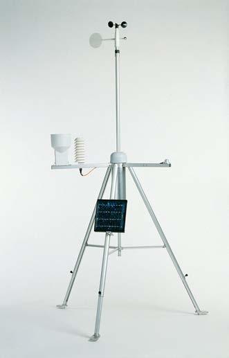
www.vaisala.com 217
Data logging memory 3.3 MB internal Flash memory
Operating humidity 0 … 100 %RH
EMC immunity EN 61326 1, industrial environment FCC part 15, class B ICES 3 (B) EMC emissions CISPR 32 / EN 55032, Class B
External memory card capacity2 GB on CompactFlash card Sensor inputs 10 analog inputs (20 single-ended 2inputs)counter/frequency inputs Internal channel for pressure sensor BARO 1 External powering 8 … 30 V DC Power consumption < 10 mA / 12 V (typically with basic 5 sensors)
Mechanical Specifications Weight Example Portable system with 3 m (9 ft 10 in) tripod (pressure, temperature/ humidity, and wind sensors) 15 kg (33.07 lb) Basic Enclosure Dimensions (H × Ø) 420 × 120 mm (16.54 × 4.72 in) Weight 3 kg (6.61 lb) Materials Anodized aluminum IP rating NEMA 4X, IP66 Sensors Wind QMW102/WMS302, WXT530 Pressure BARO-1QML Air temperature, relative humidityHMP155 Solar radiation QMS101/SP Lite2, QMS102/CMP3, QMN101/NR Lite2
UHF radio modem set SATEL3ASET-M2
Mains power QMP213 85 … 264 VAC Mains power QMP201C 1) 85 … 264 VAC 1)With 12 W solar panel and 7 Ah backup battery.
Soil/Water temperature QMT103, QMT107, QMT110 Soil moisture ML2x Options and Accessories Communication modules DSU232, DSI486 Mains power supply QMP213 Solar/Mains power supply QMP201C Carrying cases for MAWS201 QMM110, QMM120
Communication specifications Serial Standard RS 232 2 wire RS 485 SDI 12 Optional 2 optional plug in slots for communication modules to increase the number of the serial I/O channels up to 8 pcs Fast serial expansion bus for connecting digital I/O module, for example Speed 300 … 38 400 bps
Inputs and outputs
Precipitation QMR101, QMR102
QML201C Powering Specifications
Compliance EU directives and regulations EMC Directive (2014/30/EU) RoHS Directive (2011/65/EU) amended by 2015/863
Configurable parameters Speed, start bits, data bits, stop bits, parity, XON/XOFF, and checksum
Compliance marks CE, FCC, ICES, RCM
Ethernet Standard IEEE 802.3 2 plug in slots for Ethernet modules DSE101 Speed 10 Mbps (10BASE T) Can also be connected to 100/1000 Mbps (100/1000BASE T) networks with 10 Mbps Parameters Full/Half duplex with autonegotiation TCP/IP Supported protocols ARP, UDP/IP, TCP/IP, FTP, SMTP, PPP (with PAP or CHAP authentication), HTTP (GET), Telnet, ICMP Echo, DHCP, NTP, DNS, serial port tunneling over TCP/IP
Technical Data Operating Environment Operating temperature −40 … +60 °C (−40 … +140 °F) Storage temperature −50 … +70 °C (−58 … +158 °C)
Processor 33 MHz, 32 bit Motorola A/D conversion 24 bit Memory 2 MB RAM and 4 MB program
•Extended operating temperature •Easyrangeto install and connect
Weatherproof Enclosure
QMP213 has a weatherproof enclosure made of durable, UV-resistant polycarbonate reinforced with glass fiber. IP rating of the enclosure is IP66. QMP213 can be mounted on a 60 mm (2.36 in) or 100 mm (3.94 in) pole mast as well as on one of the tripod legs of MAWS201. 218
QMP213 is equipped with protection circuits for transient overvoltage at both the input and the output ends, as well as replaceable fuses for both input lines. The output is fully protected against short circuits.
Vaisala Mains Power Supply QMP213 is a small outdoor power supply with a weatherproof enclosure for installations supplied with AC power.
Wide Mains Input range
QMP213 Mains Power Supply Features mains input range
QMP213 is an outdoor power supply for installations where AC power is available. The input may vary from 100 to 240 VAC with a frequency of 50 or 60 Hz. The output provides a maximum of 12 VDC, 2.5 A. Protected against Overvoltage and Short Circuits
•Wide
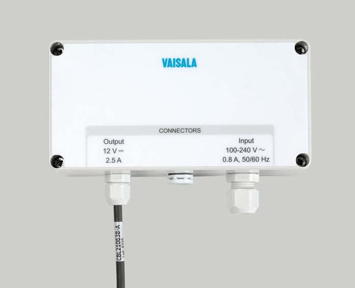
Enclosure Specifications Enclosure dimensions (W × H × D)160 × 80 × 65 mm (6.30 × 3.15 × 2.56 in) Enclosure dimensions including mounting fixture (W × H × D) 160 × 104 × 95 mm (6.30 × 4.09 × 3.74 in) Weight 0.5 kg (1 lb)
Technical Data Inputs and Outputs
Input range 100 ... 240 VAC, maximum 0.8 A, 50-60 Hz Input fuses T3.15 A / 250 A, 250 V internal fuse fitted in line and neutral Input surge protection EN61000-4-5, installation class 3 Input wiring Standard delivery does not include mains Recommendedcable. input wiring: •With a 3 wire cable (L, N, PE) •Lead dimension: 0.75 ... 1.5 mm2 (19 ... 16 •MaximumAWG)cable Ø 8 mm (0.31 in) Output voltage 12 VDC ±5% Output current Maximum 2.5 A Output protection Short circuit proof: continuous trip and restart (hiccup) Output wiring Cable with black polyurethane sheath and a female 4 pole plug (12M standard) included.
Material Polycarbonate reinforced with glass fiber Color Gray IP rating IP66 Mounting To a Ø 60 (2.36 in) or Ø 100 mm (3.94 in) pole mast or to the tripod leg Operating Environment Operating temperature −40 ... +60 °C (−40 ... +140 F°) Storage temperature −50 ... +70 °C (−58 ... +158 F°) Operating humidity 0 ... 100% RH Compliance Electrical safety EN/UL/IEC 61010 1 Low voltage directive (LVD) EMC compliance, immunity EN/IEC 61326-1, Industrial Environment www.vaisala.com 219
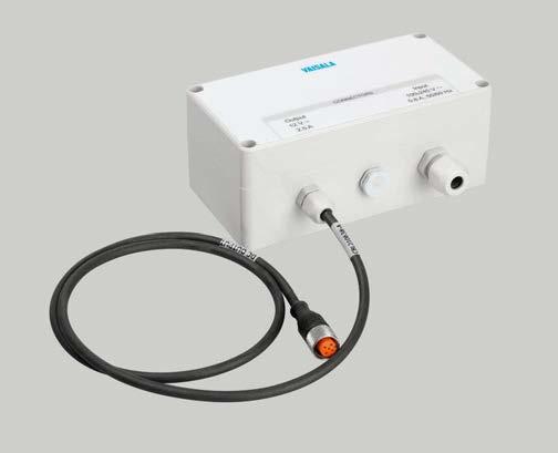
Versatile reports automatically Optionally, MAWS201M can be delivered with advanced AviMetâ software that displays numerical and graphical data and codes automatically. It also issues automatic METAR and SPECI reports based on user-defined weather events. Remarks can easily be included with Thereports.software also does the archiving and transmitting for further processing.
MAWS201M TacMet Tactical Meteorological Observation System Features • Cost-effective, quickly deployable, and portable automatic weather station •For defense operations that use small landing strips, drop zones, test ranges, UAV systems, and uncategorized airports •The most compact lightweight system with full aviation support •Reliability and precision gained through built in diagnostics and high-quality sensor technology •Robust design for harsh •Enhancedenvironmentsfreezing rain detection •Accurate second wind measurement site to assist approach • Preconfigured digital displays to distribute data to the command center
Full aviation support with enhanced systems MAWS201M is easily enhanced with the needed support for aviation. An additional optical sensor set enhances the basic system with sensors for cloud height and coverage, visibility, present weather, and lightning detection. Furthermore, it is possible to add a remote wind site and digital displays to the system. A freezing rain sensor option is also MAWS201Mavailable.includes a handheld display for setting station-specific parameters and for viewing measured and calculated parameters and system alarms. Maximum portability and ease of use Mechanical parts of the system are lightweight but robust, and all cables are fitted with quick-release color-coded connectors. The carrying cases are light, yet they provide excellent cushioning during transport.
Reliability and highest precision MAWS201M processes statistical calculations, performs data quality control, and formats data for output.
Vaisala TacMet MAWS201M is a portable weather station that o ers high performance in a compact package. MAWS201M is designed to be used in various environments and in any weather.
220
Compact and lightweight basic system MAWS201M measures, processes, and reports data from wind speed and direction, air temperature, relative humidity (dew point), pressure, and precipitation. The system is powered either by AC (mains) power or by an integrated solar panel. Backup batteries are available, providing a minimum of 7 days of operation without recharging.
Built-in quality control software validates sensor data against user-set limits and step changes between successive Inmeasurements.caseofunlikely malfunction, MAWS201M automatically detects failures, and the sensor can be replaced quickly on site.
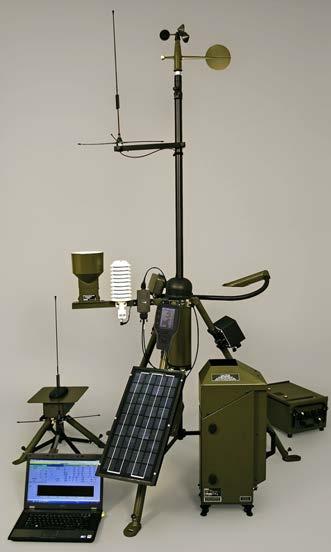
Wireless communication UHF, VHF Landline communication RS 232 For other communication options, please contact Vaisala.
Electrical safety EN 60950 EMC compatibility EN 61326 1, industrial environment EMC emissions CISPR 32 / EN 55032, Class B Compliance marks CE, FCC, ICES, RCM www.vaisala.com 221
Standard communication options
Data collection platform Vaisala Data Logger QML201C MTBF > 12 500 h (MIL HNDB217F)
Inputs and outputs AC (mains) power 100 … 240 V AC, ±10 % 50 … 60 Hz Solar panel 13 W Overvoltage category II Internal battery Basic system (continuous operation without AC power) 7 Ah / 12 V With optical sensors (min. 24 h operation without AC power) 48 Ah / 12 V With remote wind site (min. 24 h operation without AC power) 24 Ah / 12 V Battery regulator for enhanced systemsCharge/Recharge control Temperature compensation Deep discharge protection Simultaneous inputs from solar and AC power allowed
Technical data
Cloud height and coverage (CL31M)–Visibility and present weather (PWD22M)–Wind speed and direction (WMT700)–Freezing rain (LID 330IP)
Weather data reports METAR, SPECI Sensor options Sensor Basic Enhancement Wind speed and direction (WMS302M)
Operating environment Operating environment Outdoor use Use in wet location Yes Operating temperature 1) 2) −50 … +60 °C (−58 … +140 °F), cold start at −40 °C (−40 °F) Storage temperature −50 … +70 °C (−58 … +158 °F)
Setup time Basic system < 15 min With optical sensors 30 min With remote wind site 30 min 1)
1)For further extended range, please contact Vaisala. 2)For internal battery storage and operating temperature range, see manufacturer documentation.
1)Total setup time depends on location and distance of additional wind sites and displays.
Data validation, calculations, and reports
Data quality control Upper/Lower climatological limits Step change validation Sensor status indication Statistical calculations Averaging over user-configurable Minimum/Maximumperiods values Standard Cumulativedeviationvalues
Other calculations Dew QNH,pointQFE, QFF, PA, DA, pressure tendency, pressure trend Gust, peak, squall Modified discomfort index
Compliance EU directives and regulations Low Voltage Directive (2014/35/EU) EMC Directive (2014/30/EU) RoHS Directive (2011/65/EU) amended by 2015/863
Operating humidity 0 … 100 %RH, non condensing Maximum wind speed 35 m/s (70 kts) Pollution degree 2 Maximum operating altitude 3000 m (approx. 9800 ft) IP rating IP66
Optional freezing rain sensor (Enhancement 3) 1 × carry case, 12 kg (26.46 lb)
Tripod mast Adjustable from 1.8 to 3.6 m (6 to 12 ft) Optional telescopic mast 10 m (30 ft) Weight Basic system 2 × carry case, 44 kg (97 lb) Basic system and optical sensors (Enhancement 2) 4 × carry case, 115 kg (253.53 lb) Basic system, optical sensors, and remote wind site (Enhancement 2 and Enhancement 1) 6 × carry case, 176 kg (388.01 lb)
Mechanical specifications
Atmospheric pressure (BARO 1) Temperature and relative humidity Rain/Precipitation(HMP155) (QMR101M)
The handset channel has a dual tone multi frequency signaling (DTMF) receiver. Vaisala Audio Unit AUD211 AUD211 provides voice generation over radio. It communicates with QML data logger through an RS 232 port. AUD211 uses the onboard CompactFlash card as a voice data memory. The logger communicates with AUD211 through an RS 232 line and controls in symbolic format which words and phrases the AUD211 is voicing out. The voice message is voiced to radio, handset, and speaker audio channels.
AUD111 is a USB soundcard that generates audible voice messages and receives speech data, such as Notices to Airmen (NOTAMs), as an input. The voice is transferred between the central data unit (CDU) and AUD111 as WAV files (8.0 kHz, 8 bit, mono). The voice message is voiced to the following audio output channels: radio, handset, and speaker. The handset is a local phone that can be used for listening weather reports and recording NOTAMs.
•Supports and generates spoken weather messages over radio, PSTN modem line, handset, and
AUD211M provides voice generation over PSTN modem line with an RS 232 interface to QML data logger. It includes an integrated 25.4 × 63.5 mm (1 × 2.5 in) PSTN modem module. AUD211M is used when QML data logger is speaking weather reports over a PSTN modem line. AUD211M can also speak to radio, handset, and speaker channels.
Vaisala Audio Units AUD111/AUD211/AUD211M are used for generating spoken weather messages over radio, PSTN modem line, handset, and speaker. 222
Vaisala Audio Unit AUD211M
•Supportsspeaker voice recording, for example recording NOTAMs
AUD111, AUD211, and AUD211M Audio Unit
Features
•Supports the communicationfollowingoptions: voice over USB or CompactFlash
•Wide operating temperature range and industrial level EMI tolerance
Vaisala Audio Unit AUD111
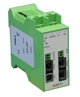
AUD211AudioVaisalaUnit(symbolicRS-232format)
Other interfaces
Power input Supply voltage 9 … 30 V DC Power consumption Maximum 5 W, 0.5 W in power shutdown
Serial port speed 1200 … 57 600 bps Handset connector RJ45 (pin 6: GND, pin 4: RxD, pin 5: TxD)
Connector RJ45 USB Speed USB 1.1, 12 Mbit/s
AUD211/AUD211M interfaces Audio input Source Handset or line in Maximum signal 1.25 Vpp Volume control i2c potentiometer with 64 steps Bandwidth 10 … 3400 Hz ADC 8 kHz, 8 bit, mono, 3400 Hz elliptic anti aliasing filter
Connector Type B SQ and radio in digital inputs
Modem Multitech MT9234SMI L 92.R1 Ring detection Separate ring detection circuit that can wake up the audio unit from low power mode
Connector 2 position screw terminal www.vaisala.com 223
AUD111AudioVaisalaUnitUSB(WAVfile)
AUD111 interfaces dataQMLlogger
digitalPSTNaudioaudioaudioout(speaker)out(radio)andkeyingout(handset)line(voiceanddata)input(squelch)modemincludesAUD211MCompactFlashvoicedataonPSTNmodule
digitallineaudioaudioaudioout(speaker)out(radio)andkeyingout(handset)in/handsetininput(squelch)
Common characteristics for each channel Volume control i2c potentiometer with 64 steps Bandwidth 10 … 3400 Hz DAC 8 kHz, 8 bit, mono
Operating environment
Operating humidity 0 … 100 %RH, non condensing
Connector 2 position screw terminal Fuse 1.1 A PTC
Dimensions (W × H × D) 45 × 99 × 113 mm (1.77 × 3.90 × 4.45 in) Weight (without modem and CompactFlash card) 220 g (7.76 oz) Case material Polyamid PA 6.6 Mounting 35 mm (1.38 in) DIN rail Audio outputs Speaker output Maximum power 1.4 W to 4 Ω 1.0 W to 8 Ω Connector 2 position screw terminal Radio output Maximum signal 9 Vpp at Rload = 10 kΩ Connector RJ45 (pins 5 and 6: audio, pins 4 and 7: keying, pin 3: +12 V) Isolation 3880 Vrms, 600 Ω transformer coupling Connector RJ45 Handset output Maximum signal 0.5 Vpp Supply for handset 19 V at 0 mA, 15 V at 55 mA Connector RJ45 (pins 4 and 5: audio) Isolation 3880 Vrms, 600 Ω transformer coupling
Technical Data VaisalaCDU
Operating temperature −40 … +60 °C (−40 … +140 °F)
Vin low −0.5 … +0.8 V Vin high +2.0 … +15.0 V Connector 2 position screw terminal Phoenix Contact MC 1,5/2 ST 3,81 PSTN (AUD211M only)
Transient protection 33 V, 1.5 kW / 1 ms transil diode Reverse connect protection Yes EIA/TIA 232 (RS 232)
DTMF detection In handset line Line in connector 2 position screw terminal Handset connector RJ45 (pins 4 and 5: audio) Isolation in handset line 3880 Vrms, 600 Ω transformer coupling Compliance EMC emissions CISPR 22 / EN 55022, Class B EMC susceptibility, test level industrial ESD EN 61000 4 2 RF field EN 61000 4 3 Fast transient bursts EN 61000 4 4 Transient surges EN 61000 4 5 Conducted RF EN 61000 4 6 Mechanical specifications
QMD102M is specifically designed for demanding military use in all weather conditions without any additional protection. It has a bright 4.3-inch color LCD display that is visible in direct sunlight. A night mode is also available. The user-friendly brightness control allows the display to be optimized for all light conditions. Usability The simple user interface enables easy operation without any additional documentation or training. The mechanical design enables operation with protective gloves. The navigation buttons allow basic operations to be done one-handed, and the removable silicon cover provides perfect grip.
Modern Display Design
The QMD102M display is easy to use and navigate. The layout includes a graphical wind display, a multi-parameter display that shows all parameters in the same page, and dedicated displays for enhancement options. A specific alarm display gives clear instructions to solve any problems with the system. QMD102M has an advanced maintenance terminal window with pre-configured function keys for the most common commands.
Compatibility QMD102M can be used in all MAWS201M systems from the very first units up to the newest generation with all the latest enhancement options. Based on the parameters provided by MAWS201M, the terminal adapts automatically to the system in case. All parameters are stored in the MAWS201M unit itself. Testing The environmental characteristics of QMD102M are designed and tested according to MILSTD-810G. EMC compliance has been tested according to IEC 61000 and CISPR 22 standards. Additional water tightness tests have been done to prove the design of the terminal. 224
QMD102M Handheld Terminal Features •Bright display visible even in direct sunlight •Easy to use •Robust design • Tested against MIL-STD-810G and •CompatibleIEC6100 with all generations of MAWS201M
Vaisala Handheld Terminal QMD102M is a new-generation terminal for Vaisala TacMetâ Tactical Meteorological Observation System MAWS201M.
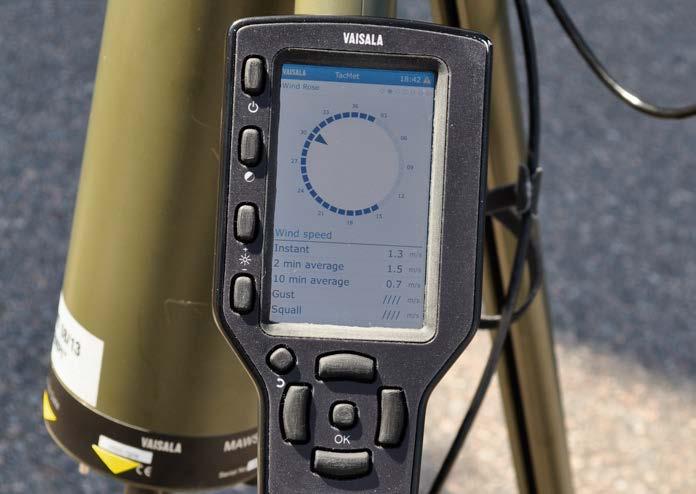
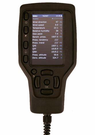
Technical Operating environment Operating temperature −40 … +60 °C (−40 … +140 °F) Storage temperature −60 … +70 °C (−76 … +158 °F) humidity 0 … 100 %RH, non condensing IP rating IP66 Inputs and outputs Supply voltage 9 … 30 V DC Average power consumption < 0.9 W Max. power consumption 1.5 W Mechanical specifications Dimensions (H × W × L)1) 200 × 95 × 30 mm (7.87 × 3.74 × 1.18 in) Weight 0.6 kg (1.32 lb) Cable length 2 m (6 ft 7 in) Display 4.3" 480 × 800 color TFT 1)Without mounting bracket and cable.
Data
Operating
EMC Conducted RF immunity EN 61000 4 6 Surge EN 61000 4 5 Electric fast transient EN 61000 4 4 RF field immunity EN 61000 4 3 Electrostatic discharge EN 61000 4 2 Emissions CISPR 22 / EN 55022, Class B www.vaisala.com 225
Compliance Environmental Low pressure MIL STD 810G 500.5, procedure I and II High temperature MIL STD 810G 501.5, procedure I and II Low temperature MIL STD 810G 502.5, procedure I and II Temperature shock MIL STD 810G 503.5, procedure I CI Solar radiation MIL STD 810G 505.5, procedure I and II Rain MIL STD 810G 506.5, procedure I, II and III Humidity MIL STD 810G 507.5, procedure II non-hazardous Salt fog MIL STD 810G 509.5, General Sand and dust MIL STD 810G 510.5, procedure I Vibration MIL STD 810G 514.6, procedure I and II Shock MIL STD 810G 516.6, procedure I and IV Icing/Freezing rain MIL STD 810G 521.3 Freeze/Thaw MIL STD 810G 524, procedure I, II, and III
For Use in Leased-line Modem
Connections DXL421 is a leased line modem for weather stations and other systems and sensors. For example, modem unit in the transmitting end can be inside the weather station enclosure and the modem unit in the receiving end can be inside the central data unit rack.
Device Mounting
The operation mode and settings are selectable with the DIL switch and jumpers. 226
•V.23 1200/1200 bps FSK
The DXL421 unit is compact: 80 x 76 x 25 mm (3.15 x 2.99 x 0.98 in). It can be mounting on a standard DIN-rail connected into various enclosures. DXL421 can be mounted, for example, to Vaisala Device Mounting and Powering Frame MDF101, or inside the weather station enclosure, or inside a large enough field sensor enclosure. Connections and Standards DXL421 can be used to connect the weather station to the leased line 2 wire or 4 wire point to point or multipoint application. DXL421 has face connectors where the power supply, RS 232, and leased line can be connected.
•V.22 1200/1200 bps differential phase shift keying (DPSK)
•V.21 300/300 bps frequency shift keying (FSK)
DXL421 Leased Line Modem Features •Support for standard DIN rail •Suitable•Compactmountinghousingforbothsensor sites and central •Suitablesitesfor2 wire or 4 wire point to point or multi point applications
Vaisala Leased Line Modem DXL421 is designed for leased line modem connections between central site and sensor sites.
DXL421 supports standards such as:
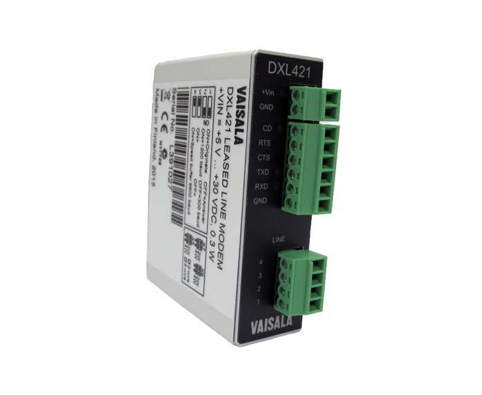
Transient protection Yes, 350 V surge protector, PTC fuses, SIDACtorâ Isolation 1500 V Connector 4 position screw terminal
DXL421 mechanical specifications
227
Housing material EN AW 1050A aluminum, gray anodized Dimensions (H × W × L) 80 × 76 × 25 mm (3.15 × 2.99 × 0.98 in) Weight 94 g (3.31 oz) DXL421 compliance Vibration IEC 68 2 64 Fh, 10 … 500 Hz, up to 2.0 G Free fall IEC 68 2 32 Ed, fall height 1000 mm (39 in) Cold IEC 68 2 1, −40 °C (−40 °F) 16 hours Heat IEC 68 2 2, +55 °C (+131 °F) 16 hours Slow change of temperature, 1 °C/min IEC 68 2 14, −40 … +55 °C (−40 … +131 °F), 2 cycles Immunity ESD EN 61000 4 2, contact dis. 4 kV, air dis. 8 kV RF field EN 61000 4 3 Fast transient bursts (EFT) EN 61000 4 4 Transient surges EN 61000 4 5 Conducted RF EN 61000 4 6 www.vaisala.com
Technical Data DXL421 operating environment Operating temperature −40 …… +55 °C (−40 … +131 °F) Storage temperature −60 … +75 °C (−76 … +167 °F) Operating humidity 0 … 100 %RH, non-condensing IP rating IP30 NEMA rating NEMA 1 DXL421 inputs Supply voltage +5 … +30 V DC Power consumption 0.09 W Fuse 0.5 A PTC Transient protection Yes, transil diode Reverse connect protection Yes Connector 2 position screw terminal Indicator Green power LED DXL421 serial RS 232 interface Topology EIA/TIA 232 F (RS 232C) interface Serial port speed 300 … 57 600 bps Connector 6 position screw terminal Indicators 3 orange LEDs: CD, TxD, and RxD DXL421 PSTN interface Modem compatibility •V.21 300/300 bps FSK •V.22 1200/1200 bps DPSK •V.23 1200/1200 bps FSK • 2 wire or 4 wire, point to point or multi point
•Maintenanceinstallationfree
•Foundation
Vaisala Short Pole Masts DKP204W (4 m high), DKP203W (3 m high), and DKP202W (2 m high) are suitable for a wide range of surface weather and climatological applications.
DKP204W, DKP203W, and DKP202W Short Pole Masts
Features
•An optional insulated guy wire (for DKP204W) and air terminal provide maximum lightning safety set includes all the necessary parts for quick and easy aluminum/ stainless steel construction are suitable for air for a wide range of automatic weather station applications
•Packages
•Easily tilted down for equipment installation and maintenance when equipped with the optional tilt division flange
The mast tubes of Vaisala Short Pole Masts DKP204W, DKP203W, and DKP202W are made of anodized aluminum. In DKP204W, the remaining parts of the main assembly are made of stainless steel to resist weathering. The masts are painted white. The optional, highly e cient air terminal protects the sensors and other equipment against lightning strikes. The air terminal with the non-conductive holders is grounded through the support guy wire, which is completely isolated from the mast. The equipment is always grounded to a separate grounding point. The foundation set includes all the parts needed to construct a steady and correctly orientated base for the mast. The only additional item needed is concrete or an existing concrete pad. With the optional leveling/welding plate, the mast can be installed also to metal surfaces. To maintain the sensors and other equipment installed on the upper mast assembly, one maintenance person can effortlessly tilt the mast when it is equipped with the optional tilt division flange. This significantly reduces the maintenance costs of weather stations. The basic mast delivery includes the mast pole and the foundation set. All the components are packed in a durable cardboard box that is suitable for air freight. 228
•Suitablefreight
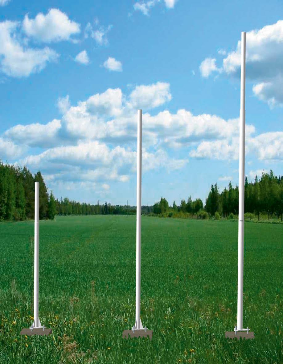
Maximum wind speed with typical weather station components 1) 30 m/s (67 mph) from all directions DKP204 with guy wires: 50 m/s (112 mph)
Technical data
Material Galvanized steel Thread of foundation bolts M16 Length of foundation bolts 220 mm (8.66 in) Wedge bolts Cast or drilled into concrete using the template provided
Operating environment
www.vaisala.com 229
Main mast assembly Height DKP204: 4 m (13 ft 1 in) DKP203: 3 m (9 ft 10 in) DKP202: 2 m (6 ft 7 in)
1)Enclosure ENC652, support arm, solar panel, radiation shield DTR13 with humidity and temperature probe HMP155, visibility and present weather sensor PWD22, and wind sensor WMT700.
Mast concrete base Soil bearing capacity Must exceed 45 kPa Coating/Painting Aluminum parts Anodized and painted Steel parts Galvanized Stainless steel parts Base: OtherPaintedparts:Uncoated Package Material Cardboard Maximum length < 3.1 m (10 ft 2 in), suitable for air freight Spare parts and accessories Item Order code 4 m (13 ft 1 in) white mast with foundation set DKP204W 3 m (9 ft 10 in) white mast with foundation set DKP203W 2 m (6 ft 7 ft) white mast with foundation set DKP202W Foundation set DKF200 2 Options Screw foundation set, length 130 cm (51.18 in) DKF200-2S13 Screw foundation set, length 200 cm (78.74 in) DKF200-2S20 Leveling/Welding plate DKP200LP 2 Tilt division flange DKP200DF 2 Support stand ASM211887SP Lightning protection kit DKL201
Diameter Lowest section: 75 mm (2.95 in) Mid-section: 63 mm (2.48 in) Top section: 60 mm (2.36 in) Weight DKP204: 21.5 kg (47.40 lb) DKP203: 17.3 kg (38.14 lb) DKP202: 13.0 kg (28.66 lb) Materials Base Stainless steel Tube Aluminum alloy Other parts, such as bolts Stainless steel DKP204 guy wires Material Stainless steel Breaking strength 28 kN Marking Black and yellow cable shrouds to the height of 2 m (6 ft 7 in) above ground Foundation set
•Can withstand winds of up to 50 m/s (112 mph); up to 75 m/s (157 mph) with 2 sets of guy wires
DKP206 and DKP210 mast tubes are made of anodized aluminum. The remaining parts of the main assembly are made of stainless steel to resist weathering.
Mast delivery contents
The optional foundation set includes all the parts needed for constructing a steady and correctly oriented base for the mast. The only additional item needed at the installation site is a concrete block of the correct size. 230
•Insulamaintenancetedguy wire and air terminal provide maximum lightning safety
Tilting for maintenance tasks
Proven wind resistance With one standard set of guy wires, the mast can withstand winds of up to 50 m/s (112 mph) when the weather station enclosure, solar panel, and sensors are installed on it. DKP210 includes an optional second guy wire set, which enables it to withstand winds of up to 75 m/s (157 mph).
•With orange and white paint (DKP206AV and DKP210AV), suitable for aviation applications
Vaisala Tiltable Masts, the 6 meter DKP206 and 10 meter DKP210, are suitable for a wide range of surface weather and climatological applications. The masts are available in two colors, white (DKP206W and DKP210W) or orange and white for aviation purposes (DKP206AV and DKP210AV).
•Foundation set includes all the necessary parts for quick and easy installation
The basic mast delivery includes the air terminal with grounding cable, one set of guy wires, and the lifting rod. All the components are packed in durable cardboard boxes that are suitable for air freight. Lightning safety
DKP206 and DKP210 Tiltable Masts Features
The air terminal protects the sensors and other equipment. From the air terminal a down conductor runs to the grounding connector at the base of the mast. The equipment is always grounded to a separate grounding point.
•Easily tilted down by one person for equipment installation and
Quick and easy installation
One maintenance person can effortlessly tilt the mast with the optional and easily detachable tilting set. Note that the number of persons needed depends on local safety regulations. The sensors and other equipment installed on the upper mast assembly do not need to be removed when performing maintenance tasks. This significantly reduces the automatic weather station maintenance costs.
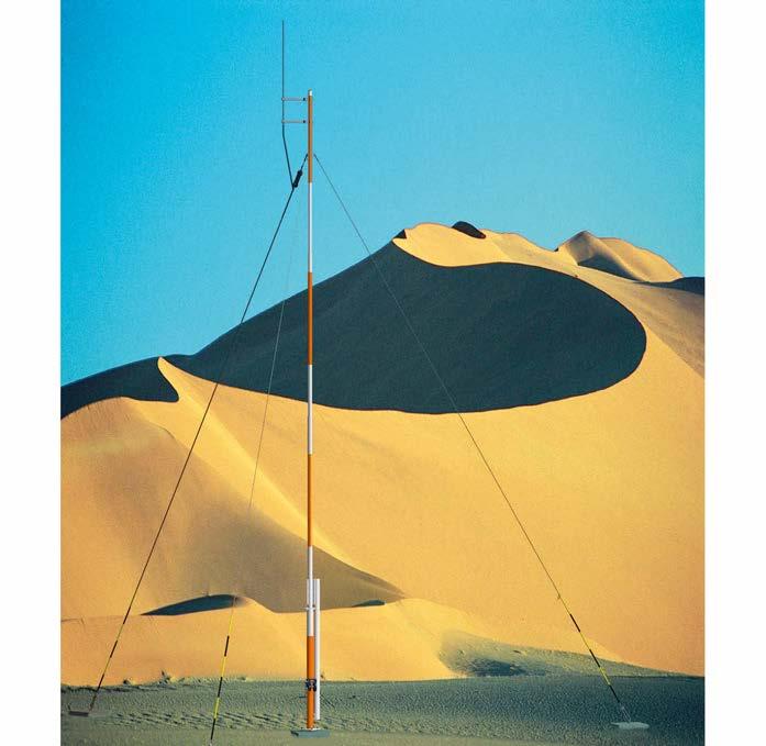
Coating/Painting
Material Cardboard Maximum length < 3.1 m (10 ft 2 in), suitable for air freight Weight (packaged with DKF200, DKL200, and DKP200) DKP206: 105 kg (232 lb) DKP210: 125 kg (276 lb) Spare parts and accessories
Main mast assembly Height DKP206: 6 m (19 ft 8 in) DKP210: 10 m (32 ft 10 in) Maximum wind speed With 1 set of guy wires: 50 m/s (112 Withmph)2sets of guy wires DKP210 only): 75 m/s (168 mph)
Second section (1.9 … 4.9 m / 6 ft 3in … 16 ft 1 in) 75 mm (2.95 in)
Foundation set Material Galvanized steel Thread of foundation bolts M20 Length of foundation bolts 300 mm (11.81 in) Wedge bolts Cast or drilled into concrete using the provided orientation template Mast concrete base Soil bearing capacity Must exceed 45 kPa
231
Third section 63 mm (2.48 in) Highest section 50/60 mm (1.97/2.36 in)
Top of the mast 60 mm (2.36 in)
Material Tube and lifting rod Aluminum alloy Base and hinge, bolts, and similarStainless steel Guy wires Material Stainless steel Breaking strength 28 kN (6295 lbf) Marking Black and yellow cable shrouds to a height of 2 meters (6 ft 7 in) above the ground
Lifting rod DKP200LR Guy wire set DKP210GW 1 Lightning protection kit DKL201 Options Foundation set DKF200 1 Winch and tilting support DKP200IS Winch DKW200 Tilting support DKP200TS Additional guy wire set for DKP210 DKP210GW 2 www.vaisala.com
Lowest section (0.0 … 1.9 m / 0 ft … 6 ft 3in) 100 mm (3.94 in)
Item Order code Tiltable mast with basic accessories, 10 m (32 ft 10 in), aviation orange DKP210AV
Technical data
Tiltable mast with basic accessories, 10 m (32 ft 10 in), whiteDKP210W Tiltable mast with basic accessories, 6 m (19 ft 8 in), aviation orange DKP206AV Tiltable mast with basic accessories, 6 m (19 ft 8 in), whiteDKP206W
Basic accessories
Diameter
Aluminum parts Anodized and painted Steel parts Galvanized Pedestal tube Corrosion-resistant powder coating Stainless steel parts Base and hinge Painted Other parts Uncoated Packages
• GRP material is recyclable
DKE110F Guyed Frangible Mast
•Suitable for a wide range of meteorological automatic weather station applications
Excellent Weather Resistance
•Withstands winds up to 60 m/s (134 mph); up to 75 m/s (168 mph) with two sets of guy wires
Vaisala Guyed Frangible Mast DKE110F is 10 meters (33 feet) high and suitable for a wide range of surface weather and climatological applications, including locations at the airports. 232
•Recycling according to EU directive 2008/98/EC DKE110F mast tubes are made of glassfiber reinforced plastic (GRP) which has very good weathering properties. The same material is also used for the guying sets. Though the mast is light weight, even with one set of guy wires it is rigid enough to resist wind speeds up to 60 m/s (134 mph) with the weather station enclosure, solar panel, and sensors installed. With the optional second guy wire set, DKE110F withstands winds of up to 75 m/s (168 mph).
•Hinged base with options to tilt manually or with a winch
The hinged base allows the mast to be manually tilted down for easy maintenance of the sensors and other equipment installed on the upper assembly. Optionally, the mast can be fitted with a separate lifting rod device to allow tilting the mast with a winch.
The Choice for Airport Locations
DKE110F is an excellent choice for airport locations. The mast is frangible according to ICAO Annex 14 and ICAO Doc 9157, Aerodrome Design Manual, Part 6 –Frangibility.
Mast Delivery Contents
Environmental Impact
Tilting for Easy Maintenance
•Glass fiber reinforced plastic material is UV stabilized and RF transparent to electromagnetic signals, such as instrument landing system (ILS) and microwave landing system (MLS)
DKE110F has excellent corrosion and environmental resistance verified with salt spray and solar radiation tests. The metal parts are made of anodized aluminum alloy and maritime grade stainless steel to achieve excellent weather resistance.
The mast delivery consists of the basic round tube mast complemented with the appropriate accessories, such as foundation, air terminal, and top guying set. An optional middle guying set kit is available for even increased maximum wind load tolerance. The mast components are packed in durable containers suitable for air freight. Features •Low mass and frangible according to ICAO Annex 14 and ICAO Doc 9157, Aerodrome Design Manual, Part 6 – Frangibility
•Manufacturing process consumes far less energy than with aluminum or steel mast
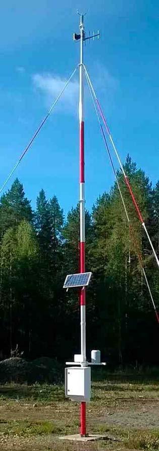
Foundation set package Dimensions (L × W × H) 385 × 275 × 110 mm (15.16 × 10.83 × 4.33 in) Weight 12 kg (26.5 lb)
Technical Data
Maximum wind speed (top guying)60 m/s (134 mph) Maximum wind speed (top and middle guying) 75 m/s (168 mph) Compliance Frangibility certification ICAO Aerodrome Design Manual Part 6: Frangibility Doc 9157 AN/901 1st edition, 2006 FAA Advisory Circular (AC) 150/5345 45C Material certifications
Number of guy wire rods 18 pcs (top guying) or 30 pcs (top and middle guying)
Material Mast tubes 1, 2, and 3 Glass fiber reinforced plastic (GRP) Top section Aluminum alloy Base and hinge Aluminum alloy Other parts Aluminum alloy or maritime grade stainless steel Fasteners Maritime grade stainless steel Guy wires and optional rods
Aluminum parts Anodizing and painting Steel parts Galvanized Stainless steel Painted Packaging Material Plywood Mast package Dimensions (L × W × H) 3100 × 500 × 390 mm (122.05 × 19.69 × 15 35 in) Weight 48 kg (106 lb)
Coating/Painting
Solar radiation test STD 810F, Method 505.4, Paragraph 4.4.3., Procedure II www.vaisala.com
233
Salt spray test STD 810F, Method 509.4, Paragraph 4.5.2., Procedure I
Breaking strength 15 kN Material Rod GRP Fasteners Maritime grade stainless steel Lifting rod (optional) Aluminum alloy Tilt rod (optional) Aluminum alloy Foundation set Material Galvanized steel Thread of foundation bolts M20 Length of foundation bolts 350 mm (13.78 in), cast in or drilled to concrete
GRP Painting, red and white in 7 sections (ICAO compliant, others available on request)
Operating environment
Mechanical specifications
Height, assembled Total: 10 m (32 ft 10 in) Mast tube 1: 0 … 3 m (0 … 9 ft 10 in) Mast tube 2: 3 … 6 m (9 ft 10 in … 19 ft 8 in) Mast tube 3: 6 … 9 m (19 ft 8 in … 29 ft 6 in) Top section: 9 … 10 m (29 ft 6 in … 32 ft 10 in) Length Mast tubes 1, 2, and 3: 3 m (9 ft 10 in) Teachopsection: 1 m (3 ft 4 in) Diameter Mast tubes 1, 2, and 3: 106 mm (4.17 in) Top section: 60 mm (2.36 in) Weight (mast only) 35 kg (77 lb)
•Withstands wind speeds of up to 60 m/s (134 mph)
•
DKE110W/AV Composite Pole Mast
•With 2 sets of guy wires, withstands wind speeds up to 75 m/s (168 mph)
Features •Painted white (DKE110W) or red/ orange and white (DKE110AV) Suited for surface weather and climatological
applications
Lightweight but Rigid DKE110W/AV mast is lightweight, but rigid enough to withstand wind speeds of up to 60 m/s (134 mph) with 1 set of guy wires. With 2 sets of guy wires, the mast can withstand wind speeds of up to 75 m/s (168 mph). Weather Resistant The mast tubes of DKE110W/AV are made of glass-fiber reinforced plastic (GRP) which has very good weathering properties. To achieve excellent weather resistance, the metal parts of the mast are made of anodized aluminum alloy and maritime grade stainless steel. Vaisala Composite Pole Mast DKE110 is a 10 meter (33 feet) mast that is available with white (DKE110W) and with red/orange and white (DKE110AV) painting. The mast is suitable for a wide range of surface weather and climatological applications. 234
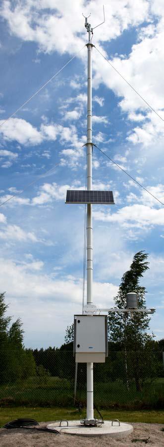
Diameter Mast tubes 1, 2, and 3: 106 mm (4.17 in) Top section: 60 mm (2.36 in) Weight (mast only) 35 kg (77 lb) Material Mast tubes 1, 2, and 3 Glass fiber reinforced plastic (GRP) Top section Aluminum alloy Base and hinge Aluminum alloy Other parts Aluminum alloy, glass fiber reinforced plastic (GRP), or maritime grade stainless steel Fasteners Maritime grade stainless steel Guy wires Material Maritime grade stainless steel Fasteners Maritime grade stainless steel Guy wires, top guy wire set 3 pcs Guy wires, middle guy wire set (optional) 3 pcs Length 11 m (36 ft)
Height, assembled Total: 10 m (32 ft 10 in) Mast tube 1: 0 … 3 m (0 … 9 ft 10 in) Mast tube 2: 3 … 6 m (9 ft 10 in … 19 ft 8 in) Mast tube 3: 6 … 9 m (19 ft 8 in … 29 ft 6 in) Top section: 9 … 10 m (29 ft 6 in … 32 ft 10 in) Length Mast tubes 1, 2, and 3: 3 m (9 ft 10 in) Teachopsection: 1 m (3 ft 4 in)
Mechanical specifications
Maximum wind speed (top guying)60 m/s (134 mph) Maximum wind speed (top and middle guying) 75 m/s (168 mph)
Technical data
Cardboard mast package with plywood reinforcements Dimensions (L × W × H) 318 × 51 × 42 (125.20 × 20.08 × 16.54 in) Weight 11 kg (24.5 lb) Foundation set package Dimensions (L × W × H) 385 × 275 × 110 mm (15.16 × 10.83 × 4.33 in) Weight 12 kg (26.5 lb) www.vaisala.com 235
Material Galvanized steel Thread of foundation bolts M20 Length of foundation bolts 350 mm (13.78 in), cast in or drilled to concrete Coating/Painting Glass-fiber reinforced plastic (GRP) parts Painted, white (DKE110W) Painted, red/orange and white (DKE110AV)
Foundation set
Operating environment
Aluminum parts Anodized and painted Steel parts Galvanized Stainless steel parts Painted Packaging Plywood mast package Dimensions (L × W × H) 311 × 52 × 43 cm (122.44 × 20.47 × 16.93 in) Weight 52 kg (115 lb)
DKE200 Frangible Lattice Mast Features •Meets ICAO and FAA standards •Built in frangibility •Fully impact tested •Transparent to electromagnetic radiation – no interference with airport •Composite•Optionalequipmentcommunicationpassiveairterminalprotectssensorsandotherequipmentstructureprovidessuperiorairterminalinsulation
Vaisala Frangible Lattice Mast DKE200 is a lightweight and rigid mast especially suited for aviation use. The mast complies with ICAO and FAA standards and is compatible with all Vaisala weather stations.
The mast is supplied with a bottom hinge, allowing maintenance from a crane truck without lowering the mast. A center-hinged version is also available, allowing the mast to be lowered by a single maintenance worker for easy maintenance of the sensors and other equipment. Note that the number of persons needed depends on local safety
The DKE200 mast is rigid and strong but lightweight, and its composite structure makes it brittle in case of sudden impact. In collision, the mast breaks at the point of impact without causing hazard to the aircraft. Robust and corrosion-resistant build
Custom options for all kinds of airports
The DKE200 mast materials comply with aviation safety specifications and the mast is impact tested according to the ICAO Aerodrome Design Manual Part 6, chapter 5 and FAA AC 150/5345 45C, section 4.
Anregulations.optional passive air terminal is available for protecting sensors and other equipment. The composite materials of the mast provide superior air terminal insulation. 236
Fully compliant with safety specifications
The DKE200 mast withstands wind speeds of up to 60 m/s (134 mph). The composite materials resist fatigue, corrosion, and other effects of weather and temperature, making the masts also suitable for marine and other corroding environments.
As composite materials do not distort electromagnetic signals of the airport communications equipment, the need to calibrate instrument landing system (ILS) antennas is reduced.
The DKE200 mast is maintenance free.
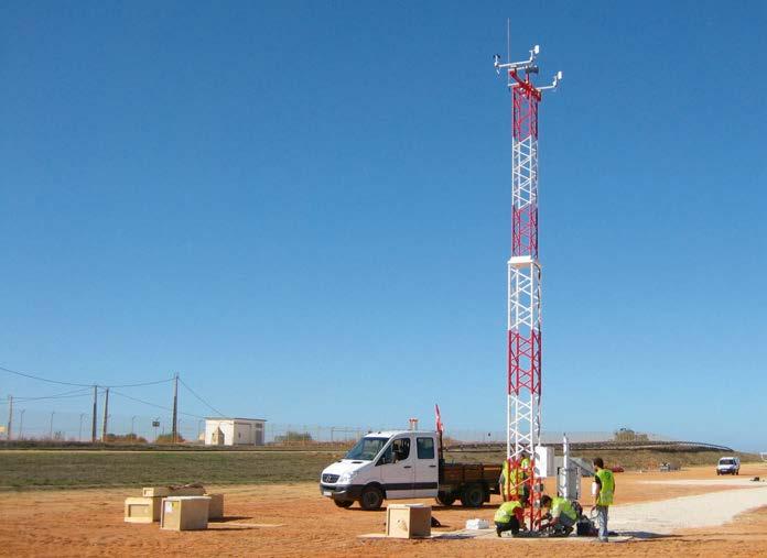
Technical data
Top frame and spigot Aluminum Base frame and foundation kitGalvanized steel Crossbar, sensor support tubes, and joining element Glass-reinforced plastic (GRP)
Frangibility certification
Top frame with spigot (Ø × L) 60 × 1000 mm (2.36 × 39.37 in)
www.vaisala.com 237
Height, assembled 10 m (32 ft 10 in) Dimensions Upper mast module (H × W × L)400 × 400 × 3750 mm (15 75 × 15 75 × 147.64 in)
Maximum wind load 60 m/s (134 mph)
Lower mast module (H × W × L)500 × 500 × 5550 mm (19.69 × 19.69 × 218.50 in)
ICAO Aerodrome Design Manual Part 6: Frangibility Doc 9157 AN/901 1st edition, 2006 FAA Advisory Circular (AC) 150/5345 45C [395.28]100403750 [147.64] 5550 [218.50] 1000 [39.37] mm [in] Dimensions
Materials Main mast assembly Glass reinforced plastic (GRP)
Sensor support arm at 2 meter (3 foot) height Aluminum Painting Orange (RAL2004) and white (RAL9016) in 7 sections according to ICAO Annex 14 and FAA AC 150/5345 45C Red (RAL3020) and white (RAL9016) in 7 sections according to ICAO Annex 14 Packaging Plywood, suitable for air freight
Operating environment
Mechanical specifications
modelProduct NO2 NOO3 COPM 1) Gases ✔✔✔✔ Particles ✔ Gas particlesand ✔ ✔ particlesandGases ✔✔✔✔✔ 1)Includes PM10, PM2.5, PM1
Vaisala Air Quality Transmitter AQT530 measures the pollution content of ambient air. AQT530 is available in di erent models for measuring gases, particles, or both.
The supplementary air quality measurement of AQT530 modernizes the way air quality can be monitored. It offers totally new value for money by measuring the most important pollutants in one compact package. AQT530 is available in different models, and configurations can be selected based on the needs. State-of-the-art technology
238
Easy to deploy in networks AQT530 is specifically designed for air quality monitoring networks in areas with tra c, road networks, or around transportation hubs. Thanks to its small weight, compact size, and good precision it is ideally suited for deployment especially in large air quality networks. The measurement data can be sent wirelessly to a web-based database with a gateway solution and it is also available locally through a serial AQT530interface.can be paired with Vaisala Beacon Station to provide a professionalgrade complete network solution with best-in-class accuracy and reliability.
For gas measurements AQT530 utilizes industry standard electrochemical gas sensor technology. By using proprietary advanced algorithms, individual factory calibration, and improved humidity robustness, parts per billion (ppb) concentrations at different environmental conditions can be measured reliably in one compact package. Algorithms compensate for the impact of ambient conditions and aging of the sensor elements, removing the need for costly gas sampling and Particlesequipment.are measured with a state-ofthe-art proprietary laser particle counter (LPC). Single particles scatter light and based on the scattered intensity and number of pulses detected, the particle sizes and mass concentrations are calculated.
AQT530 Air Quality Transmitter Features •Measures important urban pollutant gases (NO2, NO, O3, and CO) and particles (PM10, PM2.5, PM1 •Proven) laser particle counter (LPC) technology with pulse height analyzer for measuring particulate matter •Intelligent humidity management for gas sensor elements •Robust temperature and humidity sensor using Vaisala HUMICAPâ •Compacttechnologydesign and easy to deploy in the field •Factory calibrated •Field performance derived from global long-term multi-site and multi-continent field tests 1)
1)Test locations include Beijing, China; Helsinki, Finland; Jakarta, Indonesia; Lapland, Finland; London, UK; New Mexico, Arizona, US; Paris, France; São Paulo, Brazil.
Applications •Air quality supplemennetworkstingexisting regulatory stations • Air quality measurements in smart city and urban applications monitoring •Building automation •Air quality research New value in air quality measurements
•Roadside
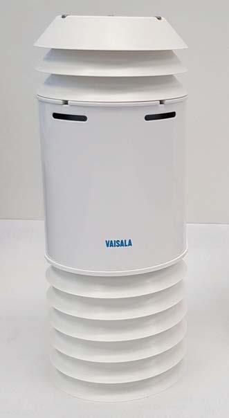
Measurement performance – particles
1)Spherical equivalent size of DEHS particles. Lower detection limit of 0.6 μm defined as 50 % detection efficiency for DEHS particles. 2) Specified with ISO12103 1, A1 ultrafine test dust.
3)Water uptake of particles may result in PM overestimation. In most cases this is indicated by the sensor. 4) Specified for gas measurement device only.
Property PM2.5 PM10 Size range 1) 0.6 … 2.5 μm 0.6 … 10 μm Concentration range 2) 0 … 1000 μg/m3 0 … 2500 μg/m3 Detection limit 0.1 μg/m3 0.1 μg/m3 Accuracy 3) 5 % 6 % Precision 3) 4) 2 % 2 %
Color, radiation shield White (RAL9003)
2) Typical R2 against a reference grade instrument derived from field tests globally. 3)Mean absolute error against reference. 4)Mean absolute difference of AQT530 reading from average reading of AQT530s.
Data output Modbusâ ASCII, Modbusâ RTU, ASCII CSV Serial data interface RS 485 Maintenance interface 1) RS 232
Material, base module Anodized aluminum Material, radiation shield Polycarbonate (PC) Power and data connector Standard 8 pin M12 male Compliance EU directives and regulations EMC Directive (2014/30/EU) REACH Regulation (EC 1907/2006) RoHS Directive (2011/65/EU) amended by 2015/863
Dimensions (H × Ø) 335 × 133 mm (13.19 × 5.24 in) Weight, with mounting kit 2.4 kg (5.29 lb)
Property NO2 NOO3 CO Concentration range2000 ppb2000 ppb2000 ppb10ppb000 Detection limit 5 ppb5 ppb5 ppb10 ppb
3)Measured against a certified reference grade instrument at room temperature using Arizona dust equivalent (ISO12103-1, A1 Ultrafine test dust). PM2.5 measured at 150 μg/m3 and PM10 at 1300 μg/m3 Accuracy and precision are defined with 2 standard deviations. 4)Unit-to-unit variation. Defined as difference of AQT530 reading from average reading of AQT530s.
Humidity Accuracy for sensor element 0 … 90 %RH: ±3 %RH 90 … 100 %RH: ±5 %RH Resolution 0.1 %RH Temperature Accuracy for sensor element 0.3 °C (0.17 °F) at +20 °C (+68 °F) Resolution 0.1 °C Pressure (indicative) Accuracy 15 hPa Resolution 1 hPa Operating environment Operating temperature −30 … +40 °C (−22 … +104 °F) 1) Storage temperature +20 … +25 °C (+68 … +77 °F) Operating humidity 15 … 100 %RH, non condensing 2) 3) Storage humidity 20 … 75 %RH Operating pressure 800 … 1150 hPa IP rating IP65 4)
Technical Data
Data connection specifications
Property 1) NO2 2) NO O3 2) CO Correlation with reference 3) R2: 0.70R2: 0.75R2: 0.50R2: 0.85 Accuracy 4) 7 ppb15 ppb11 ppb183 ppb Unit to unit correlation 5) R2: 0.93R2: 0.96R2: 0.84R2: 0.97 Precision 5) 3 ppb3 ppb4 ppb25 ppb
3)Maximum consumption when humidity > 85 %RH.
www.vaisala.com 239
EMC immunity 1) EN 61326 1, industrial environment EMC emissions CISPR 32 / EN 55032, Class B Cold IEC 60068 2 1 Dry heat IEC 60068 2 2 Damp heat IEC 60068 2 78 Eye safety IEC 60825 1:2014 Class 1 laser product Compliance marks CE, China RoHS, FCC, RCM, UKCA
Mechanical specifications
Property 1) PM2.5 PM10 Correlation with reference 2) R2: 0.65 R2: 0.75 Accuracy 3) 9 μg/m3 13 μg/m3 Unit to unit correlation 4) R2: 0.97 R2: 0.97 Precision 4) 2 μg/m3 3 μg/m3
1)All values are based on 1 hour averages with factory calibration, no linear correction applied. Values are obtained from global field testing in major climate zones against reference instruments. The values represent typical values and may be different based on the location. 2)At 10 V/m RF field test, the presence of electromagnetic interference in the range of 800 … 900 MHz may cause additional deviation for NO2 and O3 3) Typical R2 against a reference grade instrument derived from field tests globally. 4)Mean absolute error against reference. 5)Mean absolute difference of AQT530 reading from average reading of AQT530s.
Gas and particle measurement 1.8 … 4.4 W 2) Gas measurement 1.4 … 3.8 W 3) Particle measurement 1.7 … 2.0 W 4)
1)Recommended Vaisala USB maintenance cable kit (253163SET).
1)Optimal performance at −10 … +30 °C (−14 … +86 °F). 2)Optimal performance at 15 … 90 %RH. Operation in low-humidity environments may weaken the gas measurement performance. Operation in high-humidity environments may weaken the particle measurement performance.
Measurement performance – gases
Powering Operating voltage 10 - 25 V DC Max. 1 A at 10 V DC 1) Power consumption, max. peak 1) 10 W Power consumption (average with default settings)
2)Maximum consumption when humidity > 85 %RH, temperature < 0 °C (32 °F), default particle measurement cycle.
1)At 10 V/m RF field test, the presence of electromagnetic interference in the range of 800 … 900 MHz may cause additional deviation for NO2 and O3
4)Maximum consumption when temperature < 0 °C (32 °F), default particle measurement cycle.
Field performance – particles
Measurement performance – environmental parameters
1)Humidity management active, particle measurement active, temperature < 0 °C (32 °F).
Field performance – gases
1)All values are based on 1 hour averages with factory calibration, no linear correction applied. Values are obtained from global field testing in major climate zones against different reference equivalent methods. The values represent typical values and may be different based on the location and reference instrument. Majority of particle mass within size range.
WXT530 Series Weather Transmitter Features •Right parameter combination •Easy to use and integrate •Weather parameter hub •Analog sensors can be added •Compact, lightweight •Low power consumption •mA output suitable for industrial applications • •DNVCost-effectiveGLTypeExamination
DNV GL TYPE EXAMINATION CERTIFICATE No. TAA00000VF 240
Flexibility WXT530 is a series of weather instruments that provides 6 of the most important weather parameters: air pressure, temperature, humidity, rainfall, wind speed and direction through various combinations. You can select the transmitter with the needed parameter(s) into your weather application, with a large variety of digital communication modes and wide range of voltages. A heated option is available. Low power consumption enables solar panel applications. WXT530 Series focuses on maintenance-free operations in a cost-effective manner. Integration The series offers analog input options for additional third-party analog sensors. With the help of the built-in analog-todigital converters, you can turn WXT530 into a small, cost-effective weather parameter hub.
Vaisala Weather Transmitter WXT530 is a unique series of sensors with parameter combinations that allow you to choose what is right for your application. WXT530 is a flexible, integrated building block for weather applications. WXT530 series improves your grip on weather.
OptionRainWindPTU 1) WXT531 ✔ WXT532 ✔ WXT533 ✔✔ WXT534 ✔ WXT535 ✔ ✔ WXT536 ✔✔✔ 1)PTU
Additional parameters include solar radiation and external temperature sensor. Further, the analog mA output for wind speed and wind direction enables a wide variety of industrial applications.
changeable module.
changing it every
WXT530 exceeds IEC60945 maritime standard. Solid performance WXT530 Series has a unique Vaisala solid-state sensor technology. To measure wind, Vaisala WINDCAPâ ultrasonic wind sensors are applied to determine horizontal wind speed and direction. Barometric pressure, temperature, and humidity measurements are combined in the PTU module using capacitive measurement for each parameter. This module is easy to change without any contact with the sensors. The precipitation measurement is based on the unique acoustic Vaisala RAINCAPâ Sensor without flooding, clogging, wetting, and evaporation losses. is a compact Vaisala recommends 2 years.
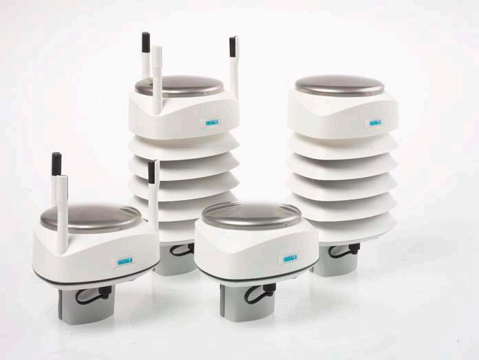
Technical data
Observation range −52 … +60 °C (−60 … +140 °F) Accuracy (for sensor element) at +20 °C (+68 °F) ±0.3 °C (±0.54 °F) Output resolution 0.1 °C (0.1 °F)
WXT536 analog input options
Collecting area 60 cm2 (9.3 in2) Rainfall 1) Output resolution 0.01 mm (0.001 in)
1) Due to the measurement frequency used in the sonic transducers, RF interference in the 200 … 400 kHz range can disturb wind measurement.
1)Cumulative accumulation after the latest automatic or manual reset. 2) Cumulative number of hits against collecting surface.
Heating voltage DC, AC, or full-wave rectified AC 12 … 24 V DC (−10 … +30 %) 12 … 17 V ACrms (−10 … +30 %)
Compliance EU directives and regulations EMC, RoHS EMC compatibility EN 61326 1, industrial environment CISPR 32 / EN 55032, Class B Environmental IEC 60068 2 1, 2, 6, 14, 30, 31, 78 IEC 60529, VDA 621 415 Maritime IEC 60945 (Exposed) DNV GL Type Examination Certificate No. TAA00000VF
Observation range 500 … 1100 hPa Accuracy (for sensor element) at 600 … 1100 hPa ±0.5 hPa at 0 … +30 °C (+32 … +86 °F) ±1 hPa at −52 … +60 °C (−60 … +140 °F) Output resolution 0.1 hPa / 10 Pa / 0.001 bar / 0.1 mmHg / 0.01 inHg
Compliance marks CE, RCM, RoHS, China RoHS, UKCA
Intensity output resolution 0.1 mm/h (0.01 in/h) Hail 2) Output resolution 0.1 hits/cm2 (1 hits/in2), 1 hit Intensity output resolution 0.1 hits/cm2h (1 hits/in2h), 1 hit/h
Barometric pressure measurement performance
Relative humidity measurement performance
Operating environment Outdoor use Operating temperature −52 … +60 °C (−60 … +140 °F)
Air temperature measurement performance
Azimuth 0 … 360° Response time 0.25 s Available variables Average, maximum, and minimum Accuracy ±3.0° at 10 m/s (22 mph) Output resolution 1° Averaging time 1 … 3600 s, sample rate 1, 2, or 4 Hz (configurable)
Storage temperature −60 … +70 °C (−76 … +158 °F) Operating humidity 0 … 100 %RH Operating pressure 500 … 1100 hPa Wind 1) 0 … 60 m/s (0 … 134 mph) IP rating Without mounting kit: IP65 With mounting kit: IP66
Operating environment
Observation range 0 … 100 %RH Accuracy (for sensor element)±3 %RH at 0 … 90 %RH ±5 %RH at 90 … 100 %RH Output resolution 0.1 %RH Wind measurement performance Wind speed Observation range 0 … 60 m/s (134 mph) Reporting range 0 … 75 m/s (168 mph) Response time 0.25 s Available variables Average, maximum, and minimum Accuracy ±3 % at 10 m/s (22 mph) Output resolution 0.1 m/s (km/h, mph, knots) Wind direction
Field accuracy for daily accumulationBetter than 5 %, weather-dependent Duration Counting each 10 second increment whenever droplet detected
Duration output resolution 10 s Intensity Running 1 minute average, 10 s steps Intensity observation range 0 … 200 mm/h (0 … 7.87 in/h) (broader with reduced accuracy)
Operating voltage 6 … 24 V DC (−10 … +30 %)
www.vaisala.com 241
Precipitation measurement performance
Inputs and outputs
Typical heating current 12 V DC: 800 mA, 24 V DC: 400 mA Digital outputs SDI 12, RS 232, RS 485, RS 422 Communication protocols SDI 12 v1.3, Modbus RTU, ASCII automatic and polled, NMEA 0183 v3.0 with query option
Average power consumption Minimum: 0.1 mA at 12 V DC (SDI 12 Tstandby)ypical:3.5 mA at 12 V DC (typical measuring intervals) Maximum: 15 mA at 6 V DC (constant measurement of all parameters)
Mechanical specifications Weight WXT534, WXT535, WXT536 0.7 kg (1.54 lb) WXT531, WXT532, WXT533 0.5 kg (1.1 lb)
When the analog output option is applied, digital communication is not Windavailable.speed 0 … 20 mA or 4 … 20 mA Wind direction 0 … 20 mA or 4 … 20 mA
Solar radiation 0 … 25 mV Voltage input 0 … 2.5 V , 0 … 5 V, 0 … 10 V Tipping bucket rain gauge 0 … 100 Hz Temperature (Pt1000) 800 … 1330 Ω WXT532 analog mA output options
DNV GL TYPE EXAMINATION CERTIFICATE No. TAA00000VF 242
Vaisala WINDCAPâ Ultrasonic Wind Sensor WXT532 is designed for demanding applications where stable and inexpensive wind measurements are required.
WXT532 incorporates decades of Vaisala experience in wind measurement using ultrasound to determine horizontal wind speed and direction. With no moving parts, the sensor has high sensitivity as the measurement time constant and starting threshold are virtually zero. This makes it superior to conventional mechanical wind sensors.
Low power consumption WXT532 has very low power consumption: in idle mode the device typically consumes about 2 … 3 mW.
Heating
Proven Vaisala performance
WXT532 WINDCAP Ultrasonic Wind Sensor Features •Triangular design ensures excellent data availability • Maintenance-free with no moving •Optionalparts heating available •Compact, durable, and robust •Low power consumption •IP66 housing with mounting kit •mA output suitable for industrial applications • •OptionalCost-effectiveaccredited wind calibration (MEASNET) available
The optional heating available in WXT532 assists measurements in freezing or snowy weather conditions and in humid environments. Since the heating circuit is independent of the operation power, separate power supplies can be used. Heating is switched on automatically at low temperatures, well before the freezing point.
WXT532 is designed to operate without periodic field calibration and maintenance. Applications WXT532 is ideal for use in marine applications as the housing with the mounting kit is water resistant. The sensor is also suitable for environmental monitoring, for example, for measuring wind speed and direction in automatic weather stations. Easy to install WXT532 is delivered fully assembled and configured from the factory. With Vaisala configuration software tool you can change the settings, such as averaging times, output mode, update intervals, measured variables, and message Thecontents.sensor can be mounted either on top of a pole mast or on a cross arm. When using the optional mounting kit, the north alignment needs to be performed only once.
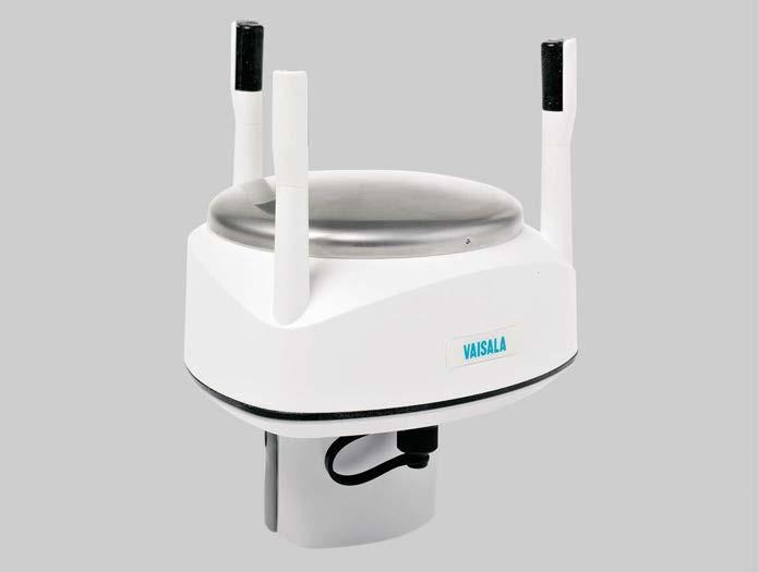
Typical heating current 12 V DC: 800 mA, 24 V DC: 400 mA
Cable 10 m shielded 8-pin M12 SP 222288 Cable 40 m shielded 12-pin, open end wires SP217020
Operating voltage 6 … 24 V DC (−10 … +30 %) Average power consumption Minimum: 0.1 mA at 12 V DC (SDI 12 Typical:standby)3.5 mA at 12 V DC (typical measuring intervals) Maximum: 15 mA at 6 V DC (constant measurement of all parameters)
Inputs and outputs
Mounting accessory between mounting kit and 60 mm tube WMSFIX60 Bird kit 212793
Operating environment Operating environment Outdoor use Operating temperature −52 … +60 °C (−60 … +140 °F) Storage temperature −60 … +70 °C (−76 … +158 °F)
Operating humidity 0 … 100 %RH Operating pressure 500 … 1100 hPa Wind 1) 0 … 60 m/s (0 … 134 mph) IP rating Without mounting kit: IP65 With mounting kit: IP66 Mechanical specifications
Cable 50 m shielded 8-pin M12, open end wires245931 Bushing and grounding accessory kit 222109 Mounting kit 212792
Vaisala configuration tool and USB service cable SP220614 Cable USB RS-232/RS-485 1.4 m USB M12 SP220782 Cable 2 m shielded 8-pin M12 SP 222287
Dimensions (H × Ø) 141 × 114 mm (5.48 × 4.49 in) Weight 510 g (1.12 lb)
Wind direction Azimuth 0 … 360° Response time 0.25 s Available variables Average, maximum, and minimum Accuracy ±3.0° at 10 m/s (22 mph)
Output resolution 1° Wind measurement frame Averaging time 1 … 3600 s, sample rate 1, 2, or 4 Hz (configurable) Update interval 1 … 3600 s (= 60 min), at 1 s steps
Materials Radiation shield, top, and bottom partsPolycarbonate +20 % fiberglass Precipitation sensor plate Stainless steel (AISI 316)
Heating voltage DC, AC, or full-wave rectified AC 12 … 24 V DC (−10 … +30 %) 12 … 17 V ACrms (−10 … +30 %)
When the analog output option is applied, digital communication is not Windavailable.speed 0 … 20 mA or 4 … 20 mA Wind direction 0 … 20 mA or 4 … 20 mA Options and accessories
DNV GL Type Examination Certificate No. TAA00000VF Compliance marks CE, RCM, RoHS, China RoHS, UKCA
www.vaisala.com 243
Wind measurement performance Wind speed Observation range 0 … 60 m/s (134 mph) Reporting range 0 … 75 m/s (168 mph) Response time 0.25 s Available variables Average, maximum, and minimum Accuracy ±3 % at 10 m/s (22 mph) Output resolution 0.1 m/s (km/h, mph, knots)
Cable USB with power supply RS-232 / 485 USB/ M12SP / 100-240 VAC 263193SP Cable 10 meter shielded 8-pin M12 CBL210679
Digital outputs SDI 12, RS 232, RS 485, RS 422 Communication protocols SDI 12 v1.3, Modbus RTU, ASCII automatic and polled, NMEA 0183 v3.0 with query option 115 [4.53] [5.55]141 [3.98]101 126.4 [4.98] 114 [4.49] 32 [1.26] WXT532 analog mA output options
Compliance EU directives and regulations LVD, EMC, RoHS EMC compatibility EN 61326 1, industrial environment CISPR 32 / EN 55032, Class B Environmental IEC 60068 2 1, 2, 6, 14, 30, 31, 78 IEC 60529, VDA 621 415 Maritime IEC 60945 (Exposed)
Vaisala Beaconâ Station BWS500 is a compact weather station for environmental monitoring. The complete solution provides measurements, data collection, and data visualization in one package. BWS500 includes Vaisala Beacon Edge Gateway EGW501, a selected set of sensors, powering equipment, and mounting accessories. To maximize ease-of-use, the station comes with a data plan and a variety of service packages to choose from. 244
•Compact end-to-end solution for various weather observation
Secure data connectivity BWS500 takes care of the measurements, as well as data storage and transfer with Vaisala Beacon Edge Gateway EGW501. EGW501 provides secure data transfer between the sensors and Wx Beacon. The integrated SIM card and cellular data plan make the station ready for use as soon as it is installed.
•Secure
BWS500 Beacon Station
To ensure su cient power supply, solar power can be used only when a nonheated version of WXT530 series sensor is selected for BWS500 configuration.
Power Supply Unit PSU501 is the powering solution for BWS500, designed to ensure uninterrupted power supply (UPS) to the station. PSU501 can be used in sites where AC (mains) power is available, and in cases where AC (mains) is not available PSU501 can work together with an environmentally friendly solar panel or other DC power PSU501source. is suitable for both portable and fixed installations. The solar panel in conjunction with low power consumption make BWS500 an ideal choice for data applications in remote locations.
•Data visualization with Wx Beacon and open API for third-party integrations Complete solution BWS500, when combined with data management and visualization software, includes the required hardware and software for managing your weather data. You can select to use Vaisala Wx Beacon for measurement data BWS500visualization.issuitable for a variety of applications and can be scaled to support both small and large-scale weather observation networks − from harbor and port weather to complementing national weather forecast networks. Sensors for measurementvariousneeds
BWS500 is easy to install and requires minimal configuration. Simply install and connect the devices, and start gathering data.
Data sharing and management
The Vaisala Wx Beacon software collects and visualizes measurement data from the station. Once you have an account in Vaisala Wx Beacon, you can share the data to third-party services and systems through an open API.
Plug and play A range of options for mast, tripod, and wall mounting are available for the station hardware, enabling optimal installation regardless of the location.
The sensor selection of BWS500 includes the proven Vaisala WXT530 Series Weather Transmitters, Vaisala Air Quality Transmitter AQT530, and Vaisala CARBOCAP Carbon Dioxide Probe GMP252. WXT530 series sensors measure air pressure, temperature, humidity, rainfall, wind speed, and wind direction. AQT530 provides measurement data of the most important urban pollutant gases (NO2, NO, O3, CO) and particles (PM10, PM2.5, PM1). GMP252 measures carbon dioxide concentration up to 10 000 ppm CO2
•Remotecommunicationsmonitoringservice
Flexible powering solution
•Acapplicationscurate,high-quality weather data with Vaisala WXT530 Series Weather Transmitters and air quality data with Vaisala Air Quality Transmitter AQT530 and Vaisala CARBOCAPâ Carbon Dioxide Probe GMP252 panel powering for installations at remote locations software platform and data for carefree operation
•Solar
Features
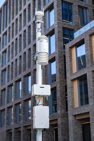
Powering Powering options •Power supply unit PSU501 for AC (mains) power and solar panel/ external DC power use •DC input without power supply unit AC (mains) power 100 ... 240 V AC, ±10 % 50 ... 60 Hz 800 mA AC (mains) fuse, internal (nonreplaceable) Type 3, 1.5 kV / 3kA AC (mains) cable connection •Conductor cross-section (flexible): 0.75 ... 2.5 mm2 (20 ... 14 AWG) •Cable lead-through: for 6 ... 12.5 mm (0.24 ... 0.49 in) cable External DC / Solar panel input15 ... 32 V DC Max. 2 A Solar panel 1) 20 W for Vaisala-provided solar panel Battery Lead-acid battery Battery capacity 12 V DC, 7 Ah Overvoltage category II Power output (PSU501) 30 W Power consumption 2) EGW501 < 0.75 W, typical 1)Solar panel feasibility and operation depends on the installation location and the amount of sunshine. 2) For power consumption of sensors, see the relevant sensor documentation.
1)Installation to concrete foundation. Optional accessories: leveling/welding plate, tilt division flange, support guy wire set (DKP204 only), and lightning protection kit. 2)Tripod comes with a toolkit, including tools bag, hammer, and ground pegs. www.vaisala.com 245
Mast 4 m (13 ft 1 in) 1) DKP204 Mast 3 m (9 ft 10 in) 1) DKP203 Mast 2 m (6 ft 7 in) 1) DKP202 Tripod 3 m (9 ft 10 in) 2) DKT504
1)For a full list of global availability, see www.vaisala.com/en/bws500-support Sensor options
Mounting options
Wall mounting kit for gateway ASM213843 Wall mounting kit for power supply units ASM213949 Mast mounting kit for gateway ASM213841 Mast mounting kit for power supply units ASM213841
Communication options Wireless communication 4G LTE / 3G / 2G Maintenance communication USB 3.0 Web UI (locally) Data collection and visualizationVaisala Wx Beacon Data interfaces •Vaisala Wx Beacon open API •Lightweight machine-to-machine (LwM2M) interface Sensor interfaces RS 485 Modbus Compliance EU directives and regulations EMC, LVD, RED, RoHS EMC compatibility EN 61326 1, industrial environment CISPR 32 / EN 55032, Class B EN FCC301489-1part15,class B ICES 3 (B) Electrical safety EN 61010 1 Cold IEC 60068 2 1 Dry heat IEC 60068 2 2 Vibration IEC 60068 2 6 IEC 60068 2 64 Change of temperature IEC 60068 2 14 Damp heat, cyclic IEC 60068 2 30 Rough handling IEC 60068 2 31 Damp heat IEC 60068 2 78 Freezing rain NWS 8.0 Compliance marks CE, EAC/CE, FCC, IC, RCM, UKCA Radio module Acceptance CE (Europe), EAC/CE (Ukraine), FCC (USA), IC (Canada), RCM (Australia and New Zealand), Giteki (Japan) 1) SIM card type Mini-SIM Frequency bands LTE-FDD B1/ B2/ B3/ B4/ B5/ B7/ B8/ B12/ B13/ B18/ B19/ B20/ B25/ B26/ B28 LTE-TDD B38/ B39/ B40/ B41 WCDMA B1/ B2/ B4/ B5/ B6/ B8/ B19 GSM B2/ B3/ B5/ B8
Technical data Operating environment Operating environment Outdoor use Use in wet location Yes Operating temperature −40 ... +55 °C (−40 ... +131 °F) 1) Storage temperature −40 ... +70 °C (−40 ... +158 °F) 1) Operating humidity 0 … 100 %RH 1) Pollution degree 2 Maximum operating altitude 2000 m (approx. 6500 ft) IP rating WXT530 series IP65, with mounting kit IP66 AQT530 IP65 2) GMP252 (probe body) IP65 EGW501 IP67 PSU501 IP65 1)Excluding AQT530. See AQT530 specifications. 2) Specified for gas measurement device only
Vaisala WXT530 Series Weather Transmitter (heated or non heated)
Vaisala Air Quality Transmitter AQT530 Vaisala Carbon Dioxide Probe GMP252
and •Remotemonitoringupdate of
operation •Integrated
Connection point for sensors
Vaisala Beaconâ Edge Gateway EGW501 is a data collection and transfer solution that provides platform-level security for Vaisala Beacon Station BWS500. The integrated radio module and SIM card, together with the compact design, allow for speedy installation and commissioning.
Remote update and diagnostics Because of the Internet connectivity, the gateway firmware can be updated remotely. With the remote device management and monitoring service, there is less need for site visits. Remote operations are supported with diagnostics to ensure speedy recovery from error situations.
•Allows
•Tested
Local management
In normal use, site visits are rare. When you need to visit the site to, for example, establish a direct connection to EGW501, a local connection is simple to establish. Simply connect your laptop to EGW501 using a USB-C cable and access the browser-based Web UI tool.
EGW501 Beacon Edge Gateway Features extensibility with 3 sensor connectors Buffers data from sensors for transfer to cloud in case of connection loss remote sensor and gateway management sensor gateway software to maximize up-to-date secure SIM card readymade data plan to endure extreme weather for status and connection
•LEDconditionsindication
EGW501 has 3 dedicated connectors for sensor-to-gateway communication, a power connector, and a connector for local maintenance connection. EGW501 supports a selected set of Vaisala sensors and, in the future, also thirdparty sensors. Data buffering and transfer EGW501 handles data transfer between the sensors and a Vaisala cloud. Additionally, it provides data collection and storage. EGW501 buffers the observation data for transmission at regular intervals. The local buffering capacity ensures that no data is lost and there are no communication breaks.
and
•
and
Cellular data service subscription EGW501 operates as a secure gateway between the weather station and the outside world. It is plug and play out of the box. Using the integrated radio and SIM card, the data is transferred over a cellular connection. The cellular data plan is available as a service for a range of countries. 246
•Enables
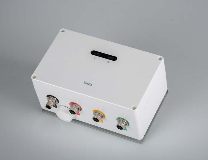
1)For a full list of global availability, see www.vaisala.com/en/bws500-support Mechanical specifications Weight 1 kg (2.2 lb) Package dimensions (L × W × H)306 × 184 × 156 mm (12.05 × 7.24 × 6.14 in) Mating connectors (sensor input) •1 × M12 8-pin male •2 × M12 5-pin male Material, enclosure Polycarbonate (PC) Material, connectors Nickel-plated brass
Mounting options and accessories Mast mounting kit for pole masts Ø 60 ... 200 mm (2.36 ... 7.87 in), includes mounting brackets, steel band, accessories, and 5-mm Allen key ASM213841 Tripod mounting kit, includes mounting brackets and accessories ASM213954 Wall mounting kit, includes mounting plate, screws, and wall plugs ASM213843 USB-C maintenance cable 1)
Operating humidity 0 … 100 %RH Pollution degree 2 Maximum operating altitude 2000 m (approx. 6500 ft) IP rating IP67 Powering Operating voltage 9 … 32 V DC Current consumption, maximum2 A Mating connector (power input)M12 A-coded 4-pin female Processing system Processor ARM Cortex A9, 800 MHz Memory 1 GB DDR3L RAM, 8 GB eMMC Flash Operating system Linux Communications protocol IPv4 Radio module Acceptance CE (Europe), EAC/CE (Ukraine), FCC (USA), IC (Canada), RCM (Australia and New Zealand), Giteki (Japan) 1) •FCC ID: 2AO39-EGW501 •ICED ID: 23830-EGW501 SIM card type Mini-SIM Frequency bands LTE-FDD B1/ B2/ B3/ B4/ B5/ B7/ B8/ B12/ B13/ B18/ B19/ B20/ B25/ B26/ B28 LTE-TDD B38/ B39/ B40/ B41 WCDMA B1/ B2/ B4/ B5/ B6/ B8/ B19 GSM B2/ B3/ B5/ B8
1)Delivered with each gateway.
Communication options Wireless communication 4G LTE / 3G / 2G Maintenance communication USB 3.0 Web UI (locally) Data interfaces Lightweight machine-to-machine (LwM2M) interface Sensor interfaces RS 485 Modbus Compliance EU directives and regulations EMC, LVD, RED, RoHS EMC compatibility EN 61326 1, industrial environment CISPR 32 / EN 55032, Class B EN FCC301489-1part15,class B ICES 3 (B) Radio compatibility EN 301 908-1 EN 301 511 FCC part 22, 24, 27, 90
Operating environment Operating environment Outdoor use Use in wet location Yes Operating temperature −40 … +55 °C (−40 … +131 °F) Storage temperature −40 … +70 °C (−40 … +158 °F)
Technical data
Electrical safety EN 61010 1 Cold IEC 60068 2 1 Dry heat IEC 60068 2 2 Vibration IEC 60068 2 6 IEC 60068 2 64 Change of temperature IEC 60068 2 14 Damp heat, cyclic IEC 60068 2 30 Rough handling IEC 60068 2 31 Damp heat IEC 60068 2 78 Corrosion and salt mist VDA 621 415 Freezing rain NWS 8.0 Compliance marks CE, EAC/CE, FCC, IC, RCM, UKCA
[3.54]90[3.94]100 200 [7.87] [4.72]120 mm [in] EGW501 dimensions and connectors www.vaisala.com 247
DKT504 Tripod Mast
•Easy
one •Portable,personcomes
Features be used in temporary and long term installations with no need for civil works for various applications to set up and dismantle by in a carry case legs allow installation on uneven ground
•Suitable
•Can
Used in many applications
DKT504 is suitable for a wide range of applications, such as meteorological and environmental research, construction, agromet, and recreational weather. It supports the attachment of BWS500 components: sensors, solar panels, and gateway and power supply unit enclosures. Portable solution DKT504 is a portable, lightweight mast that it easy to set up in a variety of locations. Its individually-adjustable legs allow installation even on an uneven terrain. Pegs are used to secure the tripod in place.
The tripod comes in a carry case and it can be easily collapsed for transportation when needed. The carry case has fastening straps inside to secure the tripod during the transportation. Delivery contents DKT504 mast tube and legs are made of anodized aluminum and it includes a toolkit, which makes it suitable for remote locations and demanding environments.
DKT504 is designed to enable the use of Vaisala BWS500 as portable weather station. Fast and easy to assemble, the tripod is suitable for temporary installations as well as for long term installations with no need for civil works. 248
Vaisala Tripod Mast
•Individually-adjustable
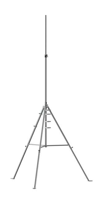
Package Type Soft shoulder bag Material Canvas Length 1350 mm (53.15 in) Diameter Ø 400 mm (15.75 in) Empty weight 2.6 kg (5.7 lb) Example weight (including tripod, toolkit, bag, and solar panel SOL501) 16.5 kg (36.4 lb)
DKT504 technical data
1)When installed on firm soil and anchored to the ground with pegs.
Maximum weight for equipment10 kg on the mast + 10 kg on the tripod legs
[63.74]1619[138.67]3522[37.13]943[81.00]2057 Ø1316[51.81] Ø2092[82.36] mm[in] 538 [21.18] [75.00]1904 [43.86]1114 Ø [1.50]38Ø30[1.18] Dimensions [46.02]1169 [43.27]1099 Ø315[12.4] www.vaisala.com 249
Maximum wind load 25 m/s 1) Maximum slope angle 30° (one leg oriented downhill)
Mast length 1114 mm (43.86 in) Mast length with extension 1904 mm (75.00 in) Base diameter 1316 ... 2092 mm (51.81 ... 82.36 in) Mast outer diameter Ø 38 mm (1.50 in) Mast extension outer diameterØ 30 mm (1.18 in) Tripod weight (legs and mast)8.7 kg (19.2 lb)
Mechanical specifications
Tripod and telescopic mast Adjustable legs and mast Height 2057 ... 3522 mm (81.00 ... 138.67 in)
Color Natural grey Materials Mast tube and legs Anodized aluminum Screws and washers Stainless steel Locking part in telescope mastComposite
Operating environment
Total weight (tripod, toolkit, and bag)13.6 kg (30 lb)
Versatile powering solution with AC (mains) powering and DC powering with an optional solar panel is available for Vaisala Beacon Station BWS500. The mounting options are similarly versatile: you can choose from mast, tripod, and wall mounting.
PSU501 for AC (mains) and DC power PSU501, when used with AC (mains) power, requires a licensed expert such as an electrician for installation. The PSU501 enclosure contains a backup battery to ensure operation during power failure or Whenoutage.used with BWS500, PSU501 provides autodiagnostic data, such as the battery level. Solar Panel 20 W Vaisala Solar Panel comes in 2 variants to allow mounting on a mast (SOL502) or tripod (SOL501).
The use of the solar panel can be considered in locations with su cient amount of sunlight. To ensure su cient power supply, the solar panel can be used only when a nonheated version of Vaisala WXT530 Series Weather Transmitter is selected for BWS500 configuration.
Versatile powering solution Power Supply Unit PSU501 is the powering solution for Vaisala Beacon Station BWS500, designed to ensure uninterrupted power supply (UPS) to the station. PSU501 can be used in sites where AC (mains) power is available, and in cases where AC (mains) is not avaible PSU501 can work together with an environmentally friendly solar panel SOL501/SOL502 or other DC power PSU501source. is suitable for both portable and fixed installations. The solar panel in conjunction with low power consumption make BWS500 an ideal choice for data applications in remote locations. 250
PSU501 Power Supply Unit and SOL501/SOL502 Solar Panel 20 W Features •Power supply unit •Weather resistant with durable polycarbonate enclosure •Includes battery backup •Autodiagnostic data available when used with Vaisala Beaconâ Station BWS500 •Installation•Easytoinstall•Mast,tripod,and wall mounting options for power supply unit •Mast or tripod mounting options for solar panel
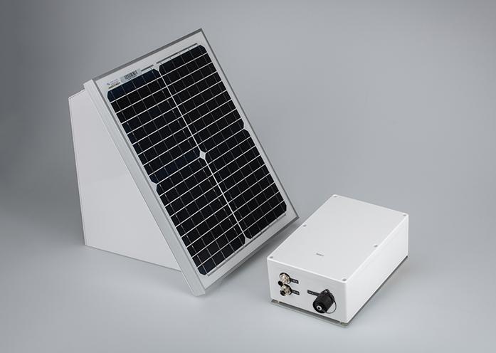
1)Power supply unit not included.
PSU501 operating environment Operating environment Outdoor use Use in wet location Yes Operating temperature −40 ... +55 °C (−40 ...+131 °F) 1) Operating humidity 0 … 100 %RH Pollution degree 2 Maximum operating altitude 2000 m (approx. 6500 ft) IP rating IP65 1)The capacity of the backup battery degrades in cold temperatures.
3)The actual output voltage equals the DC input voltage (max. 32 V). 4)Vaisala recommends, for example, YUASA NP7 12. PSU501 mechanical specifications Dimensions (H × W × L) 244.5 × 164.2 × 101.0 mm (9.63 × 6.46 × 3.98 in) Weight 4 kg (8.8 lb) Material, enclosure Polycarbonate Mating connectors • DC in: M12 A coded 4 pin female • DC out: M12 A coded 4 pin male • AC in: 4 pin female circular connector PSU501 compliance EU directives and regulations EMC, LVD, RoHS EMC compatibility EN 61326 1, industrial environment CISPR 32 / EN 55032, Class B FCC part 15, class B Electrical safety EN 61010 1 Cold IEC 60068 2 1 Dry heat IEC 60068 2 2 Vibration IEC 60068 2 6 IEC 60068 2 64 Change of temperature IEC 60068 2 14 Damp heat, cyclic IEC 60068 2 30 Rough handling IEC 60068 2 31 Damp heat IEC 60068 2 78 Corrosion and salt mist VDA 621 415 Freezing rain NWS 8.0 Compliance marks CE, FCC, RCM, UKCA PSU501 mounting options and accessories
www.vaisala.com 251
Solar panel for tripod mounting, includes mounting brackets, cable, and accessories SOL501 Solar panel for pole masts Ø 60 ... 200 mm (2.36 ... 7.87 in), includes solar panel holder, mounting brackets, steel band, cable, and accessories SOL502 SOL501/SOL502 specifications
1)In PSU501, solar panel or other external DC power supply is connected to DC in. EGW501 of Beacon Station is connected to DC out 2)DC power supply must have reinforced insulation between AC (mains) and output.
Use in wet location Yes Nominal voltage 12 V DC Maximum power 20 W Voltage at maximum power (Vmpp), typical 18.5 V
Cable, PSU501 to gateway 1) AC (mains) power connector 1) 1)Delivered with each power supply unit.
Current at maximum power (Impp), typical 1.09 A Open-circuit voltage 22.6 V Short-circuit current (Isc), typical1.19 A Dimensions (H × W × D), without mounting frame 440 × 350 × 49.6 mm (17.32 × 13.78 × 1.95 in) Dimensions (H × W × D), including mounting frame 377.5 × 350 × 319.7 mm (14.86 × 13.78 × 12.59 in) Weight, including mounting frame4.3 kg (9.5 lb)
Wall mounting kit, includes mounting plate, screws, and wall plugs ASM213949
Solar panel options
Weight, including mounting frame and power supply unit 7.7 kg (17 lb)
Technical data
PSU501 powering Input power (AC) 100 ... 240 V AC, ±10 % 50 ... 60 Hz 800 mA Input power (DC) 1)2) 15 ... 32 V DC Max. 2 A Nominal output voltage, AC input connected 24 V In backup (battery) mode: 12 V Nominal output voltage, AC input not connected 12 V 3) DC output current Max. 1.2 A AC (mains) fuse, internal (nonreplaceable) Type 3, 1.5 kV / 3kA AC (mains) cable connection •Conductor cross-section (flexible): 0.75 ... 2.5 mm2 (20 ... 14 AWG) •Cable lead-through: for 6 ... 12.5 mm (0.24 ... 0.49 in) cable Overvoltage category II Battery type 4) Valve-regulated lead-acid (VRLA) battery
Mast mounting kit for pole masts Ø 60 ... 200 mm (2.36 ... 7.87 in), includes mounting brackets, steel band, accessories, and 5-mm Allen key ASM213841
Nominal battery capacity 12 V DC, 7 Ah Expected battery lifetime 3 ... 5 years Battery dimensions (H × W × L)Approx. 97.5 × 65 × 151 mm (3.84 × 2.56 × 5.94 in)
Operating environment Outdoor use
Tripod mounting kit, includes mounting brackets and accessories ASM213954
Powering options Vaisala power supply unit for AC (mains) and DC powerPSU501 Vaisala Solar Panel 20 W 1) SOL501/SOL502
Manager also provides a wealth of current road weather information in several views and displays. Other weather data, such as radar and satellite images (if available) can be viewed with the road weather data, providing a complete weather picture.
The most critical weather information for decision making is knowing the future state of the road. RoadDSS Manager allows viewing the forecast surface state with intended treatment before confirming the plan.
The proposals do not replace an actual human decision maker, but give guidance as to what they could be doing based on best practices and approved policies. The tool is perfect for inexperienced supervisors, or agencies wanting to deliver e ciency and consistency in decision making.
With RoadDSS Manager, the decision makers get a total view of the data throughout time. Historical data is easily accessible and the displays can be viewed exactly as they appeared during an event. The data provides a learning tool for analysis of past performance with a real understanding of the RoadDSSoutcome.
Vaisala RoadDSS Manager is a road weather software system that provides maker with set of road weather data - past, present, and future RoadDSS Manager allows decision makers to access all relevant weather data, such as fixed road weather stations, mobile road weather data, vehicle tra c, satellite and radar information, in one provides a complete view of road weather data through time, by providing historical views of past information, conditions in near real-time, and predictions of conditions in the future with road weather forecasts that allow for proper planning. Using all of this information, RoadDSS Manager integrates the road authority's own operational guidelines and policies to provide treatment proposals, delivering a consistent guide for decisions makers.
Thelocation.system
tools to make operational decisions. Benefits •Treatment proposals based on your agency’s guidelines • User personalization • Customer designed interface with customizable views •Proposals can be automated or •Combinesmanual fixed, mobile, and other weather data in one platform •Hosted solution so no need to manage server(s) •Street level mapping provides improved detail •Provide
the decision
A True Decision Tool
RoadDSS Manager Features •Chemical Supply Management •Complete transportation forecast services (atmospheric, road surface and friction, consultative) •Live and archived road weather •Radardata and satellite overlay (where •Operationsavailable) management •Reporting capabilities •View multiple stations or single •Datasites import/export capabilities •Internal and CommunicationExternal
RoadDSS Manager enables the implementation plan to be tracked through to completion in the operations screen. This ensures the agency has a full audit trail of operational activity.
A final critical piece of decision making is communicating information out to the stakeholders in a e cient and uniform way. RoadDSS Manager takes care of this for you, improving your speed of decisions.
Data Across Time
252
The growing trend in decision management tools is to not only provide quality information to make a decision, but to also provide a proposed action.
a complete
RoadDSS Manager takes in current conditions, past maintenance activities, and road weather forecasts, and provides a treatment or maintenance strategy.
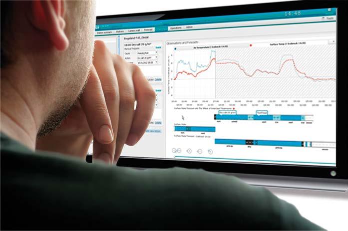
•Alert Management capability to provide weather alerts on wind speed, visibility, and slippery conditions, and choice of e-mail and/or SMS messages.
•Street level resolution map displaying station information, including air and surface temperature, surface state, wind, camera images, precipitation, humidity, tra c data and much more, depending on the sensors installed.
•Display camera image, if available, along with surface state and select weather parameters, in addition to a wind rose indicating wind speed and direction.
•
•Data Reports and Online Help
Technical Data Map Displays
Planning
•Zooming in an out capability and the ability to go back or forward 24hrs to see observed and forecast values of all station parameters. Stations
Weather Forecast Text and chart displays of multiple forecasts including Morning Summary, 24 hour forecasts, 2-5 day forecast, or other type, based on forecast supplier data.
•Ability to set up an unlimited number of routes, with the flexibility to group them according to the operational workflow.
•Ability to manually propose treatments or edit auto-propose
•Continuous tracking of events and treatment proposals.
•Ability to adjust start and end times of the operation.
253
•Display of the Stations graphs with the added benefit of seeing the forecast surface state after one or more
•User hierarchy to manage access rights and enable tailoring in accordance with job role.
•Color coded status parameters including surface temperatures, surface state, wind speed, level of grip, and
•Electronic date time and user stamp associated with each logged activity enabling comprehensive audit trail.
•Selectiontreatments.of Cause, Action, Start Time, and Comments for each of the treatment proposals (manual or automatic).
•Continuous tracking of operations
Configurable Graph Tabs
Miscellaneous
•Archiving capabilities to review past performance and decisions made. Screens display the same information that was displayed at the time.
•Wind speed and direction on a timeline that can be adjusted to see more or less past conditions and forecast.
•Surfaceactions. state displays of road conditions before and after proposed treatment, in the forecasted side of the timeline.
•Wind Rose Wall displaying wind data and threshold breach alerts from all weather stations equipped with appropriate instrumentation on the network.
Operations •Software can be used to e ciently communicate current maintenance strategies to crews and other stakeholders.
•Camera Wall showing current image displays from weather stations equipped with cameras.
•Multiple logins per customer, with user personalized displays •Comprehensive audit trail www.vaisala.com
•Optionalvisibility. displays such as radar, lightning, and terrain maps.
•Ability to add comments for justifying each operation or indicating changes to the standard procedure.
•Surface state bars showing road conditions and road state, past current and forecasted.
•Track start and end times, treatment cause, and comments for each phase of the operation.
•Forecast text describing conditions for the next hours or days.
•Auto-propose capabilities that takes the current and forecasted conditions and proposes treatment as a starting point, based on previously set up road authority guidelines.
More Features
Vaisala RoadDSS Navigator is a hosted web user interface for viewing past, present and future road weather data. The application displays data collected by the Vaisala Global Data Management Center, which handles data collection from the road weather networks around the world.
•Supportsalerts animation of radar, satellite and other map based information where available
RoadDSS Navigator Software Map view of Vaisala RoadDSS Navigator Features •Easy-to-use interface with customizable views •Works with latest versions of Microsoft Internet Explorer and Mozilla Firefox browsers •Easy to implement and maintain •Shows real-time data on a map, table or •AlertinggraphandAlarming Feature •Easy access to service from anywhere with an Internet •GISconnectionmapsoptimized for displaying road weather data
• Configurable e-mail and SMS
Browse Observations and Forecasts with Ease
Navigator also includes detailed alerting functionality that continuously monitors specific parameters you make decisions on, and then provides you with notification as soon as those thresholds are reached. Vaisala RoadDSS Navigator was designed by Vaisala customers, which means it fits into your operations more naturally.
•Historical data available
•Station data export for easy data analysis o ine
The application consists of a set of dynamic web pages that can be viewed with a simple Internet connection. The Vaisala RoadDSS Navigator also features GIS maps which are optimized to clearly display road weather data, including Thermal Mapping and mobile weather observations, where available. The Navigator user interface is part of the Vaisala RoadDSS Software Suite and provides the added functionality of providing detailed reporting. The reports save you time in compiling information from the system making your job easier.
•Generate reports quickly and in a printer friendly format
The application has many features that make browsing the data very easy. For instance, with the powerful Time Slider feature you can quickly see on the map page all the observations and any forecasts that are available for 24 hours on either side of the actual time. This gives an unparalleled overview of past, present and future conditions at a glance. It also takes less time to train staff on how to use the program, which results in a quicker return on investment. 254
• Compare and contrast road weather observations with other road information all in the same application
Customizable Views Vaisala RoadDSS Navigator has been designed with user convenience in mind. You can easily customize the application to suit your needs. This will allow you to view only the important and relevant information, which will help you focus quickly and easily on the job at hand.
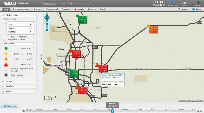
System Requirements •Internet connection •Web browser – supported browsers are Microsoft Internet Explorer v. 7 or later and the latest Mozilla •CookiesFirefoxmustbe enabled •Adobe Flash Player v. 10 or later •To view PDF reports, Adobe Reader v. 9 or later •To view data exports, Microsoft Excel v. 2003 or later
All the Relevant Data in the Same Application One of the key features in the Vaisala RoadDSS Navigator is it has the ability to compare and contrast road weather information with other relevant data. Where available this could include weather radar, satellite and tra c counting data, automatic vehicle location (AVL) data, all in the same application. With all this data in the same place you can easily see how the weather affects tra c flow, and plan your actions accordingly. In addition, some features can be conveniently animated for easy representation of moving weather events and developing situations that need monitoring.
255
www.vaisala.com
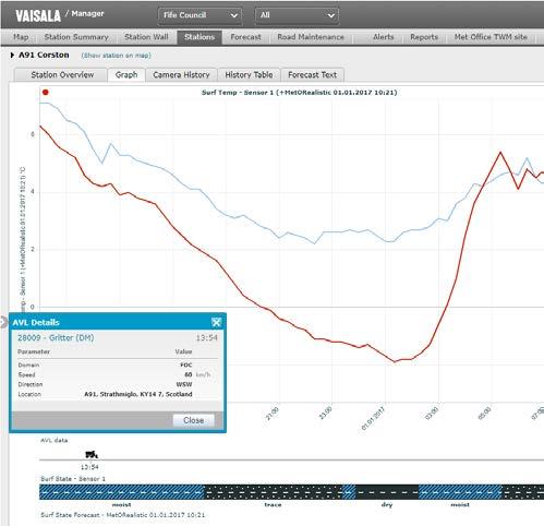
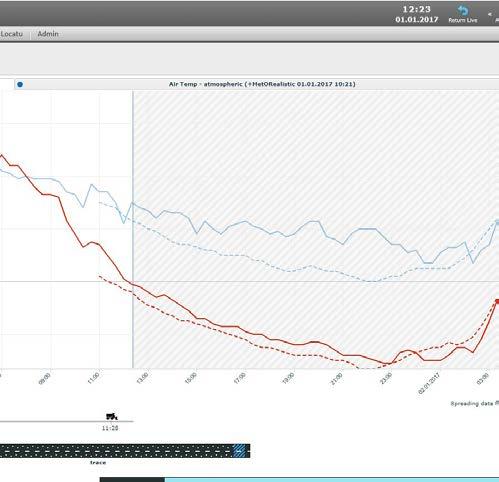

At the heart of the airport surface forecast is the model used to predict runway conditions. Vaisala incorporates a cutting-edge proprietary runway surface model called IceBreak to generate runway and taxiway surface forecasts.
•Providesforecasts.a 72-hour prediction of conditions at your airport.
•IceBreak runway surface model for generating runway and taxiway surface forecasts
Today, with so many new maintenance practices, it just as important to know what you do as when you will do it.
•Savetimesmoney through better use of
•Keepresourcesairport as safe as possible and
•Incorporates data from the Runway Weather Information System (RWIS) and your airport surface condition information into
•Lessoperationalimpactonthe environment
Reliable Decisions
Vaisala RoadDSS Navigator Runway Weather Forecast is a tool to help plan your operations, providing you with a traditional atmospheric weather forecast, and a prediction of runway and taxiway surface conditions. Vaisala Runway Weather Forecast is an optional component of the RoadDSS Navigator Software Suite, and provides you with a 72-hour prediction of conditions at your Theairport.value that Vaisala Runway Weather Forecasts provide you is the perfect combination of current observations and predicted weather conditions. To create any weather forecast, current local conditions are important, and Vaisala incorporates data from the Runway Weather Information System (RWIS) to provide a baseline for the forecast.
Intelligent Weather A key concern when building an airport maintenance weather program is making sure you have a fully integrated system that provides you the value you need. Vaisala Runway Weather Forecast is part of RoadDSS Navigator Software Suite, which means you receive both your current RWIS information within the same user interface as your airport surface condition forecasts. Combining both provides quick, easy access, and allows for integrated features, such as current and predicted values in a single graph. This means you can quickly determine how well a forecast is performing, and whether any short-term adjustments are needed.
A key to a runway surface model accuracy is the years of operation. Just like a person on the job, a model is tweaked and improved over the years to ensure it remains the industry leading model and provides you key decision information. Benefits •Be able to make confident decisions about weather
Vaisala RoadDSS Navigator Runway Weather Forecast is a tool to help plan your operations, providing you with a traditional atmospheric weather forecast, and a prediction of runway and taxiway surface conditions.
Vaisala Runway Weather Forecast is an optional component of the RoadDSS Navigator Software Suite, and provides you with a 72-hour prediction of conditions at your airport. 256
In airport maintenance knowing what is currently going on is critical to a successful maintenance operation; however, this does not provide the whole picture or tell us what is going to happen. Recognizing when to prepare for an icing event or a winter storm can save money, resources, and most importantly, lower your stress level.
RoadDSS Navigator Runway Weather Forecast
•Lessactionsstress during decision making
Features
•Tool to help choose maintenance

– hourly and
Optional available regions) access to certified meteorologist, targeted to applications access to client operations daily textual forecast storms daily weather conference call forecast length frequency forecast updates 3-hourly atmospheric forecast outlook 24-hour forecast 5-day outlook
•24/7
are available
Flexible Sources
options •Optionalavailablegraphical
and weather impacts to customer operations •Dedicated
Forecast Consultancy Services (Not
a
in all
If
for your staff Other Information •Standard
with
your
and impacts •Targeted
Technical Data Roadway Forecast Parameters Available •Roadway Forecast Parameters Available •Runway/taxiway Surface Temperature •Runway/taxiway Surface State •Runway/taxiway Sub-Surface Temperature •Runway/taxiway surface Grip Estimate •Base (Sub-Surface) Temperature Atmospheric Forecast Parameters Available •Air •Precipitation•Wind•Wind•Cloud•DewTemperaturePointTemperatureCoverSpeedDirection
is 72 hours •High
products -
products •Proactive notifications of impending
The RoadDSS Navigator Runway Weather Forecast can work with your current provider, ingesting their atmospheric weather forecast, while also providing you even more information through the Vaisala forecast. you do not already have a preferred forecast provider, Vaisala works with leading services around the globe to ensure you receive the best possible prediction. Weather Forecast appears within RoadDSS Navigator Software Suite
Runway
and
www.vaisala.com 257
to meteorologists that understand your operations •Tailored
year-round •Service
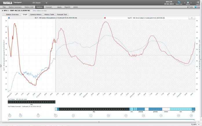
The rugged design allows MD30 to operate in snow plow trucks and other vehicles. The core is molded to withstand continuous vibration and to prevent water ingress. Further, the hood has a special vented double structure that directs air flow to protect the window from dirt and splashes.
Reliable in any weather
Measurements •Surface•Grip
MD30 Mobile Detector Features •Compact, multi-parameter mobile •Designedsensor for snow plow trucks, suitable for any vehicle • Proven DSC technology optimized for mobile •Simultaneousmeasurementswater,ice,and snow layer •Moldedreportingdesign to withstand heavy vibration and water ingress •Patent pending double-hood for window •Hand-removableprotectionhood for easy window cleaning
Output and visualization MD30 outputs a binary data message over an RS-232 interface, which can also be turned wireless with an external Bluetooth module. MD30 data can be collected and locally visualized with Vaisala RoadAI Android mobile application. The app can also be set to record video or take photos. The powerful combination of sensor data, images and video can be visualized in Vaisala Wx Horizon or Vaisala RoadAI online maps. In Wx Horizon, MD30 data can be used to improve road and runway weather forecasts and it can be combined with fixed weather station data in the same map. 258
•Air •Dewtemperaturepointandfrost
Vaisala Mobile Detector MD30 is a mobile road and runway condition sensor for winter maintenance operations. The compact MD30 measures all key surface weather parameters and is suitable for snow plow trucks and other vehicles. MD30 data is targeted to enable more accurate maintenance decision-making and salt usage optimization. state layer thickness temperature point humidity
•Surface
To provide quick response time and high sensitivity in road and runway condition reporting, MD30 utilizes an improved, fast-measuring version of the proven DSC laser technology. In cases where external heat sources could disturb the temperature measurements, the surface and air temperature sensors can be separated from the MD30 body and placed in desired locations.
•Relative
Robust for any vehicle
Easy to use and maintain MD30 provides simplicity for both use and maintenance. It starts to measure automatically when the vehicle starts, and constantly monitors the sensor status, such as the window contamination. The window is heated to avoid dew and frost formation. The sensor automatically indicates the need to clean the window. When cleaning is needed, the window can be accessed by simply removing the hood by hand, without any tools.
•Surface
Compact and cost-effective MD30 provides grip, as well as other key measurements in one package. The costeffective product allows you to use the full potential of your vehicle fleet as a data collection platform.
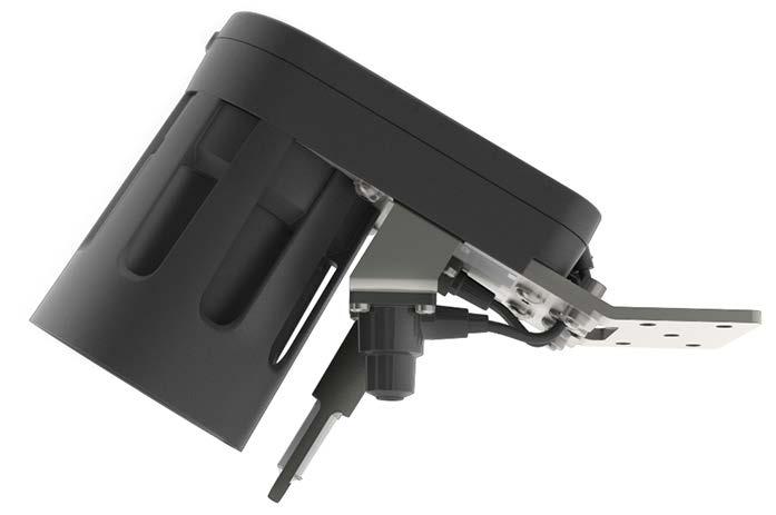
Surface temperature Measurement range −40 ... +60 °C (−40 ...+140 °F)
Operating environment Operating temperature 1) −40 ... +60 °C (−40 ... +140 °F) Storage temperature −40 ... +60 °C (−40 ... +140 °F) Operating humidity
Technical Data Measurement specifications
Grip and surface state Reported level of grip 0.09 ... 0.82 Reported surface states Dry, moist, wet, snowy, icy, slushy Surface layer thickness Water 0 … 5 mm (0 ... 0.20 in) Ice 0 … 2 mm (0 ... 0.08 in) Snow (water equivalent) 1) 0 ... 1 mm (0 ...0.04 in) Accuracy, water and ice 2) ±10 % at 0 … 2 mm (0 ... 0.08 in)
Measurement details
Measurement interval 40 times/s Light source Laser Layer thickness reporting 3 layers simultaneuously (water, ice, snow) Window dew/frost protectionHeated window Window contamination reportingClean, contaminated, heavily contaminated Window cleaning access Hand-removable hood
Air temperature and relative humidity Humidity range 0 ... 100 %RH Temperature range −40 ... +60 °C (−40 ... +140 °F) Dew point range −40 ... +60 °C (−40 ... +140 °F)
0 ... 100 %RH 1)In +35 … 60 °C (+95 ... 140 °F), surface layer thickness measurement performance may be degraded. Inputs and outputs Powering 12 ... 32 V DC Power consumption, maximum15 W Protocol RS-232 Protocol, with optional Bluetooth module RS-232-to-Bluetooth Data output Binary Data visualization on Vaisala RoadAI mobile app Mechanical specifications Sensor structure Encapsulated and molded IP rating IP68 Installation height, mobile sensor20 ... 110 cm (7.87 ... 43.31 in) Weight, mobile sensor with bracket1.8 kg (4.0 lb) 251 [9.88] 99 [3.90] 188 [7.40] [6.46]164 mm[in] 101 [3.99] Mounting options Standard mounting bracket for front, side, rear, bottom mounting MDBRACKET 1) Front towing hook mounting MD30FRONTMOUNT Rear trailer hook mounting MD30REARMOUNT 2) MD30REARKIT 3) Mounting kit for temperature sensors MD30EXTSET 1)Delivered with each MD30 sensor. 2)MD30 mounting kit for vehicle rear trailer hook. 3)MD30 sensor with mounting kit for vehicle rear trailer hook and Bluetooth module enclosure. Compliance EU directives and regulations EMC Directive (2014/30/EU) EMC compatibility EN 61326 1, industrial environment CISPR 32 / EN 55032, Class B FCC part 15, class B ICES 3 (B) Cold IEC 60068 2 1 Dry heat IEC 60068 2 2 Change of temperature IEC 60068 2 14 Shock IEC 60068 2 27 Damp heat, cyclic IEC 60068 2 30 Vibration IEC 60068 2 64 Corrosion and salt mist VDA 621 415 Eye safety IEC 60825 1 Class 1 laser product Compliance marks CE, China RoHS Data visualization on Vaisala Wx Horizon online map www.vaisala.com 259
1)1 mm (0.04 in) snow water equivalent corresponds to snow depth of approx. 10 mm (0.39 in). 2)According to laboratory measurement method as described in latest draft (2020) of EN 15518-4.
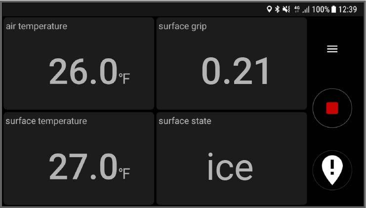
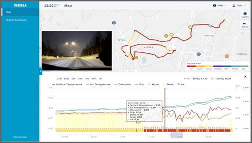
260
Pavement forecast quality can be enhanced specifically by using Ground Cast Sensor's reference-grade surface temperature and base temperature (−30 cm or −11.8 in) measurements.
Ground Cast Sensor Features •Reports observations with enhanced point forecasts •Wireless and self-powered •3+ year battery lifetime •Measures:•Temperature at 3 levels: surface, −6 cm, −30 cm (−2.4 in, −11.8 •Treatmentin) material amount •Surface state (dry / not dry) •Drilled to road, installation takes less than 30 minutes •Can be installed to various lane locations, including wheel track •Maintenance-free due to selfleveling cushion •Data•Low(patent-pending)mechanismpowerNB-IoTcommunicationavailablethroughVaisala
Measure from locations not possible before Infrastructure-free installation and wireless design of Ground Cast Sensor allow rapid deployment to virtually any location in your road network. It works as a stand-alone unit and does not require external powering or coupling with a road weather station. Ground Cast Sensor offers a cost-effective way to complement your current weather observation network with additional measurement locations.
Easy access to data
Vaisala Ground Cast Sensor provides an easy and a ordable way to get key road weather measurements from critical locations that have not been covered before. It measures road temperature and the amount of treatment materials with the same performance as Vaisala’s industry leading road weather stations.
3+ year lifetime without any maintenance needs Ground Cast Sensor includes a patentpending wear-with-road mechanism that ensures the sensor stays always leveled with the road surface. As a result, the sensor does not need maintenance during its lifetime, unlike conventional embedded sensors that may need annual grinding in roads where studded winter tires are used. The completely sealed construction makes the sensor incredibly robust and helps to minimize the risk of water leakage.
Wx Horizonâ or API Improve situational awareness and quality of pavement forecasts Because e cient winter maintenance decision-making requires understanding of current and future road conditions, Ground Cast Sensor not only reports high-quality local observations, but also enhanced point forecasts.
All wireless, yet reference grade Ground Cast Sensor provides the same reference-grade measurement quality as Vaisala road weather stations and sensors. This ensures all data from your road network is comparable and reliable.
The information provided by Ground Cast Sensor is automatically available in Vaisala Wx Horizon or alternatively as an API for integration into other systems. In Wx Horizon, the data can be visualized in the same way as other Vaisala road weather station data. The system provides a map view to understand the overall road conditions, location-specific graphs, and forecasts to provide insight into future road conditions. Configurable alerting can be set up for situations when, for example, the surface temperature drops below freezing and conditions are becoming hazardous.
Reported surface states Dry, not dry 1)
Mechanical specifications Sensor Dimensions (H × Ø) 353 × 56 mm (13.90 × 2.20 in) Weight 640 g (1.4 lb) Materials Polyurethane (PUR) Battery Type Lithium-thionyl chloride Lithium metal content 9 g per sensor, sensor includes 2 built in, non removable batteries (4.5 g / 0.010 lb each)
1)Sensor measures if there are any contaminants on top of it, but it does not differentiate between water, ice, and snow, for example. Situations other than dry are reported as “not dry”.
2)
Measurement performance
Technical data
Measurement range −40 … +70 °C (−40 … +158 °F) Measurement accuracy ±0.2 °C (±0.4 °F) at −40 … +70 °C (−40 … +158 °F) Chemical amount Supported de-icing chemicalsSodium chloride (NaCl) Calcium chloride (CaCl2) Sodium acetate (NaOOC2H3), Potassium formate (KOOCH) Magnesium chloride (MgCl) Reporting unit g/m2 Surface dryness
Operating environment Operating temperature 1) −40 … +70 °C (−40 …+158 °F) Storage temperature 2) Recommended max. +30 °C (+86 °F) Operating humidity 0 … 100 %RH IP rating IPX8: Water immersion tested under the following •Immersionconditions:depth:20m (65 ft) •Immersion time: 140 hours
Installation Recommended installation hole sizeØ 60 Depth:mmmin. 360 mm (14.17 in) Requirements for surface material 1) Paved (asphalt, concrete) Recommended installation sealants 2) Fabickâ is not designed to be installed in sand or gravel roads, as it will not stay on the surface level, and the sensor performance is optimized for paved surfaces. Vaisala recommends the use of Fabickâ sealant, but it is not available in all countries. For using locally available sealants, please check the suitability with Vaisala. [13.90]
Surface temperature Measurements 0, −6, and −30 cm (0, −2.4, and −11.8 in) (below surface)
MP-55 1)Sensor
mm [in]353
1) In extreme cold conditions where road temperature stays continuously below −20 °C (−4 °F) for multiple days, sensor battery operation might temporarily degrade. 2)Recommendation from the battery manufacturer.
[2.20]Ø56 Dimensions Communication and data collection Communication standard Narrowband IoT (NB-IoT) SIM card type Micro-SIM (3ff), provided by Vaisala Local connection for sensor setup NFC, disabled after installation Software for sensor setup Vaisala Android application Data message interval Every 10 minutes Data storage location Vaisala cloud Data access options Vaisala Wx Horizonâ user interface Vaisala Wx Horizonâ API Vaisala RoadDSSâ user interface Sensor data visualization in Vaisala Wx Horizonâ Compliance EU directives and regulations EMC Directive (2014/30/EU) EMC compatibility EN 61326 1, industrial environment CISPR 32 / EN 55032, Class B FCC part 15, class B ICES 3 (B) Electrical safety IEC 62368-1 Cold IEC 60068 2 1 Dry heat IEC 60068 2 2 Change of temperature IEC 60068 2 14 Damp heat, cyclic IEC 60068 2 30 Damp heat IEC 60068 2 78 Compliance marks CE Sensor Deployment application (Android) www.vaisala.com 261
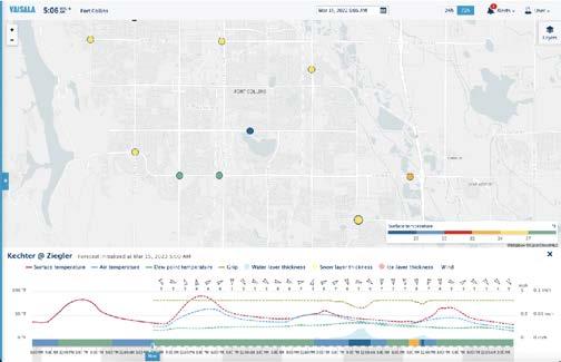
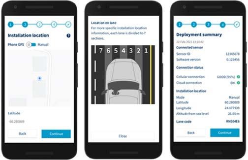
Vaisala Road Weather Station RWS200 is designed for the future of road weather systems and Intelligent Transportation Systems (ITS). RWS200 provides a complete road weather solution to improve road, rail, or runway winter maintenance activities in your organization.
To extend station operating time, PMU701 switches off sensor heating power if mains power is lost and the station is running on backup battery power. The intelligent battery management detects if the battery is faulty and stops charging it.
Timely and routine maintenance is important to the health of your road weather network and to the safety of the road Someusers.maintenance tasks, such as sensor cleaning, you cannot perform without visiting the site. For other tasks that can be performed remotely, RWS200 offers a web user interface. In addition to maintenance tasks, such as software updates, you can use the web user interface to view the observation data and the station setup.
262
RWS200 Road Weather Station Features •Reliable and quality data for educated decision making • Increased system reliability through centralized power •Localmanagementdatabase for data storage •Battery backup •Fast return of investment through operational savings •Built-in web user interface •On-site wireless network access to ease annual maintenance •Easy upgrade and sensor retrofit from previous versions Reliable data
Power and charging control Power Management Unit PMU701 makes sure that the sensors receive continuous and steady power. PMU701 also protects the sensors from power surges and switches on sensor heating power when needed.
Looking ahead The flexible, modular design of RWS200 means that a unit purchased today can be updated either remotely or in the field to support new features and functions as they are designed by Vaisala. Vaisala continuously develops RWS200 based on customer feedback.
Integration to Vaisala-hosted information services expands the possibilities to profit from the current data view of your road weather network, the winter index, and forecast services, among others.
Cost-effective maintenance
The primary requirement of a road weather station is that data is reliable and it flows from the station continuously. Road maintenance decision makers must be able to trust the information every time they make a critical RWS200decision.contains a local database which greatly improves data reliability by storing observation data. The data is not lost even if the external communication network is down for a long period of Advancedtime. communication options, such as Ethernet and 3G/4G, add reliability to the entire system and ensure continuous data flow to external systems. These options also allow remote access to the weather station for monitoring and maintenance. Advanced algorithms In addition to road weather sensors, the standard sensor options for RWS200 include a number of atmospheric sensors. Atmospheric observations greatly increase the accuracy of road weather observations, especially for embedded road sensors. Data Management Unit DMU703 contains the algorithms that further calculate the observations, such as the road surface state. DMU703 also handles the storage, analysis, and reporting of observation data.







Polled interfaces Vaisala DTO XML DATEX II NTCIP (1201 v03.15r, 1204 v03.08r2, 1204 VaisalaVaisalav04.22d)MES14MES16
Pushed interfaces Vaisala DTO XML VaisalaImagesMES 14 Vaisala MES 16 Station reports Station summary report Event log Road surface state Vaisala classes EN 15518 3 classes Communication options Standard communication options2.5G/3G/4G cellular, WLAN, and Ethernet Customer-provided communication options Cellular, Ethernet, and serial User interface Browser-based Web UI Compliance EU directives and regulations EMC Directive (2014/30/EU) Low Voltage Directive (2014/35/EU) Radio Equipment Directive, RED RoHS(2014/53/EU)Directive (2011/65/EU) amended by 2015/863 EMC immunity EN 61326 1, industrial environment FCC part 15, class B ICES 3 (B) EMC emissions CISPR 32 / EN 55032, Class B 1) Electrical safety EN 61010 1 Cold IEC 60068 2 1 Dry heat IEC 60068 2 2 Vibration IEC 60068 2 6 Shock IEC 60068 2 27 Rough handling IEC 60068 2 31 Damp heat IEC 60068 2 78 Corrosion and salt mist VDA 621 415 Compliance marks CE, FCC, ICES, RCM
Powering specifications AC (mains) power 100 … 240 V AC, ±10 % 50 … 60 Hz 5.6 A maximum (120 V AC) Mains fuse (nominal) 10 A AC (mains) surge protection Type 3, 1.5 kV / 3 kA Max. continuous voltage: 264 V AC Overvoltage category II External power 10 … 32 V DC 15 A maximum Internal backup battery Standard backplate (ENC652, BOXALU US, BOXSS US) 26 Ah / 12 V Slim backplate (ENC722) 2.6 Ah / 12 V Average operating power consumption 1) Without sensor heating 18 W At −10 °C (+14 °F) with sensor heating on 2) 102 W 1)With the following configuration: cellular router (4.7 W), DSC211, DST111, WMT700 , PWD22, two DRS511 sensors, and HMP155E. 2)DSC211 lens heating (5 W), WMT700 transducer heating (22 W), and PWD22 lens heating and hood heating (57 W). Data reporting
1)Excluding cellular router, DRD11A, RG13H, AQT530, Mobotix, and AXIS PTZ camera. See the manufacturer documentation. 2)Excluding backup battery. See the manufacturer documentation. 3)Excluding cellular router and AQT530. See the manufacturer documentation.
1)AXIS PTZ camera and Wavetronix traffic sensor emissions: Class A 263
Technical data Operating environment Operating environment Outdoor use Use in wet location Yes Operating temperature 1) −40 … +60 °C (−40 … +140 °F) Storage temperature 2) −60 … +80 °C (−76 … +176 °F) Operating humidity 3) 5 … 100 %RH Pollution degree 2 Maximum operating altitude 3000 m (approx. 9800 ft)

1)Project item.
Standard sensor options Road state, remote DSC211 Road temperature, remote DST111 Road state and temperature, embedded DRS511 Subsurface temperature DTS12G Subsurface temperature multidepth TPS10
Backplate only Vibration IEC 60068 2 6 Shock IEC 60068 2 27 Size (H × W × D) 555 × 455 × 42 mm (21.85 × 17.91 × 1.65 in) Weight after installation Approx. 12.8 kg (28.2 lb)
ENC652 IP rating / NEMA rating IP66 / NEMA 4X Approvals UL 50 / UL 50E-listing
Weight after installation BOXALU-US: Approx. 35.3 kg (77.8 lb) BOXSS-US: Approx. 55.5 kg (122.3 lb)
Tipping bucket RG13H Wind speed and direction (ultrasonic) WMT700 Wind speed and direction (mechanical) WA15 (WAC155)
Visibility and present weather PWD12/PWD22 Rain DRD11A
Wind speed and direction (combined/mechanical)R.M. Young Wind Pressure PTB110 Multiparameter WXT536 Water level SR50A Snow depth SR50A Global radiation SP Lite2 Air quality AQT530 Fixed camera Mobotix M16 Pan-tilt-zoom (PTZ) camera Axis Q6154 E Other supported sensors Air quality AQT420 Road state and temperature, embedded FP2000 Subsurface temperature DTS210 Multiparameter WXT520 Fixed camera Mobotix M12, M15 PTZ camera Axis Q6032 E, Q6042 E, Q6052 E, Q6124 E Tra c sensor SmartSensorWavetronix HD 1)
ENC722 IP rating IP66 Vibration IEC 60068 2 6 Shock IEC 60068 2 27 Size (H × W × D), incl. mounting frame, radiation shield, and cabling box 887 × 322 × 270 mm (34.92 × 12.67 × 10.62 in)
Enclosure options
Weight after installation Approx. 29 kg (64 lb) BOXALU US, BOXSS US (North America only) NEMA rating NEMA 4X Size (H × W × D), enclosure only838 × 610 × 330 mm (33.00 × 24.00 × 13.00 in)
www.vaisala.com 264
Humidity and temperature HMP155E
Weight after installation Approx. 46 kg (101 lb)
Vibration IEC 60068 2 6 Shock IEC 60068 2 27 Size (H × W × D), incl. mounting frame, radiation shield, and cabling box 787 × 581 × 270 mm (30.98 × 22.87 × 10.62 in)
With the standard ENC652 enclosure, you have a wider selection of components that fit inside the enclosure.
•Mounting316) kits for lattice towers and different size of pole masts
The backplate to which all electronics are attached is made of stainless steel.
•Additional power supply unit for the WMT700 sensor that has heated transducers and array arms
•Output socket for on-site tools or
Additional shielding Optional shielding is available for the enclosures. The set contains a cabling box that protects the cabling from vandalism and a radiation shield that protects the enclosure from excessive sunshine and falling material such as ice and tree branches. Like the enclosure itself, the shielding elements are finished with powder coating. Easy installation To ease the installation, the enclosures are delivered with a mounting frame. The mounting frame can be used to install the enclosure on a wall or on the backplate of another enclosure. Mounting accessories are also available for mounting the enclosure on a thin pole mast, a thick pole mast, or a lattice mast.
•Mains terminal strip for easier power supply connection
•Protects weather station
ENC652 and ENC722 with radiation shield and cabling box
Vaisala high-quality weather station enclosures protect weather station electronics from the weather and other damaging elements. Enclosure materials are selected to withstand harsh roadside conditions, where de-icing chemicals constantly try to contaminate the enclosure.
All installation and maintenance work can be done without the door banging on your shoulder. Standard and slim models
The enclosure door has two hinges and a wind lock to keep it open in heavy winds.
The enclosures are made of stainless steel and the seams are continuously welded for maximum strength and Rubbersolidity.
ENC652 also has room for a larger, 26 Ah / 12 V backup battery, while ENC722 can only accommodate a 12 Ah / 12 V backup battery. 265
•Residual-currentlaptop circuit breaker (GFCI)
•Acid-proofelectronics against de-icing chemicals (stainless steel AISI
Robust design
On the other hand, the slim ENC722 can be used in places where space is limited.
Features
The following components are only available with ENC652:
flanges provide cabling access through the bottom of the enclosure. The door sealing is water proof.
RWS200 Road Weather Station Enclosures
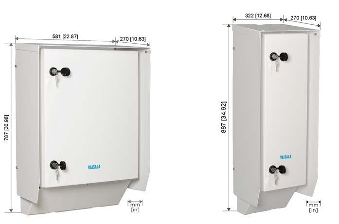
Maximum door opening angle100° Materials Enclosure Stainless steel AISI 316, painted white (RAL9003) Backplate Fe/Zn Flanges Rubber (TPE) Radiation shield Aluminum EN AW 5754 Dimensions (H × W × L) Enclosure only 600 × 500 × 207 mm (23.62 × 19.68 × 8.15 in) With radiation shield, mounting frame, and cabling box 787 × 581 × 270 mm (30.98 × 22.87 × 10.62 in) Backplate only 555 × 455 × 42 mm (21.85 × 17.91 × 1.65 in) Weight Enclosure only 14.2 kg (31.3 lb) Lifting weight (enclosure with back plate) Approx. 27 kg (59.5 lb) RWS200 shipping package Dimensions Approx. 91 × 72 × 44 cm (36 × 28 × 17 in) Weight Approx. 60 kg (132 lb)
Enclosure lock set (2 pcs) ASM213869SP Backplate assembly ASM211817SP Enclosure accessories: •Cable ties 2.5×100 mm (20 pcs) •Cable tie holders FTH 13R 01 (5 pcs) •DIN rail end brackets (10 pcs) •Washers with EPDM gasket 6.8/16×1.5/A2/EPDM (4 pcs) •Hex screws M6×16 ISO7380 A4 (2 pcs) •Hex nuts M6 Wulock Fe/Zn (2 pcs) •Torx screws M4×8 ISO14583 TX A4 (10 pcs) •Flat washers A6.4 DIN125 A4 (4 pcs) BOX652ACC1SP Accessory set, screws and washers 262928 533 [20.98] 495 [19.49] 440 [17.32] [22.05]560 [16.93]430 mm [in] ENC652 mounting frame dimensions 266
ENC652 spare parts and accessories Spare part or accessory Order code Enclosure ENC652 with mounting plate, locks and flanges, mounting frame, radiation shield, and cabling box ENC652KIT Pressure port 16941DM Cabling box ASM210466SP Radiation shield ASM210463SP Rubber flange set (2 pcs) DRFLANGE10SP
ENC652 technical data ENC652 specifications Approvals UL 50 / UL 50E listing IP rating IP66 NEMA rating NEMA 4X Maximum operating wind speed 75 m/s (168 mph)
ENC722
ENC722 spare parts and accessories
Spare part or accessory Order code Enclosure ENC722 with mounting plate, locks and flanges, mounting frame, radiation shield, and cabling box ENC722KIT Cabling box ASM211127SP Radiation shield ASM211081SP Rubber flange set (2 pcs) DRFLANGE10SP Enclosure lock set (2 pcs) ASM213869SP Enclosure accessories: ties 2.5×100 mm (20 pcs) tie holders FTH 13R 01 (5 pcs) rail end brackets (10 pcs) with EPDM gasket 6.8/16×1.5/A2/EPDM (4 pcs) screws M6×16 ISO7380 A4 (2 pcs) nuts M6 Wulock Fe/Zn (2 pcs) screws M4×8 ISO14583 TX A4 (10 pcs) washers A6.4 DIN125 A4 (4 pcs) BOX652ACC1SP set, screws and washers 262928 175 [6.89]
IP rating IP66 Materials Enclosure, mounting frame base, cabling box, nuts, washers Stainless steel AISI 316 Backplate Steel Radiation shield Aluminum EN AW 5754 Flange, gaskets, plugs Rubber (TPE) Dimensions (H × W × D) Enclosure only 700 × 200 × 207 mm (27.55 × 7.87 × 8.14 in) With radiation shield, mounting frame, and cabling box 887 × 322 × 270 mm (34.92 × 12.67 × 10.62 in) Weight Enclosure only 9.5 kg (20.9 lb) Enclosure with backplate 19.3 kg (42.6 lb) RWS200 shipping package Dimensions Approx. 86 × 40 × 34 cm (34 × 16 × 13 in) Weight Approx. 50 kg (110 lb)
•Hex
•Flat
Mounting kit for 100 mm (3.94 in) pole mast 2) APPK-SET100
Mounting kit for 80 … 600 mm (3.15 … 23.62 in) pole mast, excluding stainless steel band and locks 2) 3) DRUNIV-US
Mounting kit for 80 … 600 mm (3.15 … 23.62 in) pole mast, including stainless steel band and locks 2) DRUNIV
•Hex
1)Installation requires 1 pc of the mounting kit. 2)Installation requires 2 pcs of the mounting kit. 3) You can use any suitable stainless steel band and locks for attaching the mounting support to the pole mast, for example, Band-It 19.1 mm (0.75 in) with Ear-Lokt buckles. If you only need the band for a few installations, use the DRUNIV mounting kit instead.
www.vaisala.com 267
Mounting frame dimensions ENC652 and ENC722 mounting kit options
268 [10.55] [25.98]660 230 [9.06] [20.87]530 mm [in]
Specifications
•DIN
•Cable
•Washers
•Cable
•Torx
Accessory
Mounting kit for lattice mast 1) ASM210998
Mounting kit Order code
Mounting kit for 75 mm (2.95 in) pole mast 2) APPK-SET75
Mounting kit for 60 mm (2.36 in) pole mast 2) APPK-SET60
technical data
Web user interface
Vaisala Data Management Unit DMU703 is specifically designed and built to be the brains of Vaisala Road Weather Station RWS200. DMU703 handles the storage, analysis, and reporting of observation data. 268
In addition to managing realtime data flow, DMU703 also handles sensor calibration data, maintenance activities, and configurations, including serial numbers and software versions. To have this information available both locally and remotely helps in troubleshooting and maintaining the weather station. DMU703 contains a local database which greatly improves data reliability by storing observation data. The data is not lost even if the external communication network is down for a long period of time. Advanced algorithms DMU703 contains the algorithms that make RWS200 more than a collection of road weather sensors. The algorithms process the observation data from the atmospheric and road weather sensors and provide accurate data to support decision making.
A web user interface provides direct access to the weather station. The user interface is available locally and remotely and it is used for station setup and maintenance, as well as for viewing observation data and reports.
Features •Performs advanced algorithms based on sensor measurements •Storage for all observations, configurations, serial numbers, and maintenance history •Reliable in harsh environments •Industry-proven components that guarantee reliability and extend the life •Built-inspanweb user interface •GPS receiver for accurate time •Reliablesynchronizationinternal communications from Ethernet architecture
A DMU703 unit purchased today can be updated either remotely or in the field to support new features and functions as they are designed by Vaisala.
Effective data management DMU703 manages data flow, performs algorithm calculations, stores observation data, and provides a webbased user interface for viewing data remotely and for controlling the system.
DMU703 Data Management Unit
Looking ahead
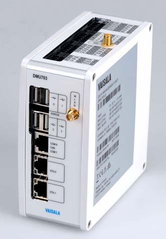
Compliance EU directives and regulations Low Voltage Directive (2014/35/EU) EMC Directive (2014/30/EU) RoHS Directive (2011/65/EU) amended by 2015/863
Supported standard USB 2.0 Signaling High speed Connectors Standard A RS 232 serial Ports COM 1, COM 5 (configurable) Signals COM 1: RXD, TXD, CTS, RTS, DTR, DSR, DCD, and RI COM 5: RXD, TXD, CTS, and RTS Connectors Phoenix Contact DFMC 1,5/3 ST 3,5 LR RS 485 serial Ports COM 5 (configurable), COM 6, COM 7 Signals D+/D− for all ports COM 5 also has R+/R− Connectors 1 × Phoenix Contact DFMC 1,5/3 ST 3,5 LR 1 × RJ45 (expansion bus) RS 485 serial, isolated Ports COM 2, COM 3 Signals R+/R−/T+/T− Connectors Phoenix Contact DFMC 1,5/3 ST 3,5 LR
Inputs and outputs
EMC immunity EN 61326 1, industrial environment FCC part 15, class B ICES 3 (B)
Ethernet Ports ETH 0, ETH 1
Other serial ports 1 × CAN (reserved) Connector: RJ45 1 × SDI-12 (reserved) Connector: Phoenix Contact DFMC 1,5/3 ST 3,5 LR Analog Lines CH A, CH B Frequency input signal 1 Hz … 20 kHz, 2.5 … 14 V DC, or 10 mV … 15 V DC Excitation voltage signal 0 … 12 V DC at 20 mA
Supported standard IEEE 802.3 Physical layer Base T Data rate 10/100 Mbps Connectors RJ45 with link LEDs USB Ports 4 (reserved)
Graphical user interface Mechanical specifications Dimensions (H × W × L) 126 × 55 × 127 mm (4 96 × 2.17 × 5 00 in) Weight 0 4 kg (0.8 lb) Mounting DIN rail 35 mm (1.4 in) Materials Screws, washers, DIN rail locking pieceStainless steel AISI 316 Frame profile Aluminum EN AW 6060 T6 Side plates Plastic PC/ABS
Damp heatIEC 60068 2 78+40 °C (+104 °F), 93 %RH
Fast input high signal 0 … 1.8 V DC, 12 bit ADC Fast input low signal 0 … 1.8 V DC, 12 bit ADC measurementSingle-ended/Differentialmode Ground Connectors Phoenix Contact DFMC 1,5/3 ST 3,5 LR
Technical data Operating environment Operating temperature −40 … +60 °C (−40 … +140 °F) Storage temperature −60 … +80 °C (−76 … +176 °F) Operating humidity 5 … 95 %RH, non condensing
Powering specifications Operating voltage 9 … 32 V DC Maximum power consumption3 W Computer specifications Processor ARM Cortex A8 Memory 512 MB DDR3 RAM, 2 GB flash Operating system Linux RTC backup battery CR2032 Web services HTTPS
VibrationIEC 60068 2 60.2 g (0.007 oz), 62 … 200 Hz 5 … 62 Hz, 1.5 mm (0.06 in) displacement Shock IEC 60068 2 273.0 g (0.106 oz) Pulse duration 11 ms with 3 pulses in each direction.
Dry heat IEC 60068 2 2+60 °C (+140 °F)
EMC emissions CISPR 32 / EN 55032, Class B Electrical safety EN 61010 1 Compliance marks CE, FCC, ICES, RCM Test compliance
I/O digital Ports 4 × input, 4 × output Input signal 0 … 30 V DC Output signal Open collector, maximum load 30 V DC at 1 A Connectors Phoenix Contact DFMC 1,5/3 ST 3,5 LR 269
Rough handlingIEC 60068 2 31Drop height 50 cm (19.69 in)
Phoenix Contact DFMC 6 pin cable connector set (10 pcs)262926
Phoenix Contact DFMC 10 pin cable connector set (10 pcs)262924
www.vaisala.com 270
Insulated ferrules 0.5 mm2, length 10 mm, white (100 pcs)237754SP
• Ethernet cable 40 cm (15 75 in)
Spare parts and accessories Spare part or accessory Order code DMU703 RWS unit including:
Time-to-first-fix Cold/Warm start 26 s Horizontal position accuracy 1) 2.5 m (8.2 ft) Antenna connector SMA (female) 1)LEP, 50 % 24-hour static, 130dBm WLAN transmitter specifications
Technical data Data reporting Polled interfaces Vaisala DTO XML DATEX II NTCIP (1201 v03.15r, 1204 v03.08r2, 1204 VaisalaVaisalav04.22d)MES14MES16 Pushed interfaces Vaisala DTO XML VaisalaImagesMES 14 Vaisala MES 16 Station reports Station summary report Event log Road surface state Vaisala classes EN 15518 3 classes GPS receiver specifications
Supported standards IEEE 802.11 b/g/n (single stream n) Transmit power +17.5 dBm, 11 Mbps, CCK (b) +14.0 dBm, 54 Mbps, OFDM (g) +12.5 dBm, HT20 MCS7 (n) Acceptance FCC, IC, ETSI, Giteki, RCM Contains FCC ID: TFB 1003 Contains IC: 5969A 1003 Antenna connector RP SMA (female)
• Phoenix Contact DFMC 1,5/3-ST-3,5-LR 6 pin cable connector (2 pc) •Phoenix Contact DFMC 1,5/5-ST-3,5-LR 10 pin cable connector (5 pc) DMU703 RWSSP
Receiver type 72 channel u blox M8 engine GPS/QZSS L1 C/A, GLONASS L10F BeiDou B1I, Galileo E1B/C SBAS L1 C/A: WAAS, EGNOS, MSAS, GAGAN
PMU701 Power Management Unit Features •Surge protection increases •Handlesreliabilityanalog, serial, and Ethernet sensors •Easy to configure and wire •Ablesensorstocycle power for individual •Optimizessensors charging voltage according to temperature •Detects faulty battery
Centralized managementpower
Continuous and steady power is a luxury for a roadside station. Power Management Unit PMU701 meets the challenges posed by power interruptions and surges caused by, for example, lightning. PMU701 provides surge protection and power to the sensors, including heating power when needed.
In total, PMU701 provides 1 external DC input, 2 solar panel inputs, 4 inputs for analog sensor communications, and 14 inputs for serial communication, 8 of which can be communication.Ethernet-based
Intelligent managementbattery
271
Simplified maintenance PMU701 has the ability to control and cycle the power of each sensor remotely, making it possible to perform some technical services remotely, such as powering down and restarting individual sensors.
All sensor communication lines and DC power lines route through PMU701 to provide surge protection between the station, the DC power supply, and the individual sensors attached to the weather station. As the RWS200 weather station enclosure is typically mounted to a pole or a metal lattice mast, lightning strikes are a real danger for the weather station.
PMU701 handles the specific power requirements of the sensors, making sure that each sensor receives steady and suitable power at all times. PMU701 is also responsible for charging the internal backup battery inside the RWS200 enclosure. If an external DC power supply is used with the road weather station, the power is routed through PMU701.
Surge protection
Simplified configuration PMU701 is designed for simplified configuration and wiring during initial setup or when adding new sensors.
Vaisala Power Management Unit PMU701 manages power and sensor communication within Vaisala Road Weather Station RWS200
Grounding each sensor cable shield is simple and easy, and a quick reference card is provided to ensure that each sensor is connected correctly; once again, to add system reliability.
Power control
PMU701 automatically detects if the backup battery is faulty, missing, or disconnected and reports it. PMU701 stops charging when the battery is faulty, the ambient temperature inside the enclosure exceeds the battery operating temperature, or PMU701 self-diagnostics detect an internal failure.
Proper power protection ensures that power disruptions are kept to a minimum, which increases the overall reliability of the system.
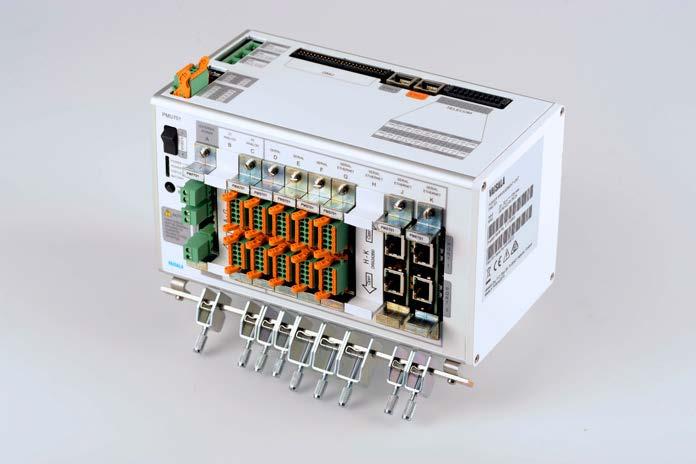
Spare parts and accessories
•Phoenix Contact DFMC 1,5/1-ST-3,5-LR 2 pin cable connectors (4 pcs)
Operating environment Operating temperature −40 … +60 °C (−40 … +140 °F) Storage temperature −60 … +80 °C (−76 … +176 °F)
•Cable ferrules 0.5 mm2 / 10 mm (100 pcs) (237754)
•Wide cover plates for empty slots (3 pcs) PMU701ACC3SP
Inputs and outputs Operating voltage 24 V DC (10 … 32 V DC)
1)SERIAL/ETHERNET slots can house either PME701 or PMS701 plug in modules. Compliance EU directives and regulations EMC Directive (2014/30/EU) RoHS Directive (2011/65/EU) amended by 2015/863
•Cable shield grounding clamps SK 8 (10 pcs) (217844)
•Phoenix Contact DFMC 1,5/8-ST-3,5-LR 16 pin cable connectors (10 pcs)
Phoenix Contact DFMC 6 pin cable connector set (10 pcs)262926
Phoenix Contact DFMC 16 pin cable connector set (10 pcs)262925
•Cable shield grounding clamps SK 14 (10 pcs) PMU701ACC2SP PMU701 accessories including: •Set of quick reference cards
•Phoenix Contact MVSTBR 2,5HC/2-ST-5.08 cable connectors (4 pcs)
Phoenix Contact DFMC 10 pin cable connector set (10 pcs)262924
DCConnectorsINPUT 23 … 32 V at 10 A Phoenix Contact MVSTBR 2,5HC/ 2 ST 5.08
EMC immunity EN 61326 1, industrial environment FCC part 15, class B ICES 3 (B)
Technical data
Operating humidity 5 … 95 %RH, non condensing
Output power 12 V at 3 A and 24 V at 7 A Maximum charging current 3.8 A (total) for 26 Ah battery 1.9 A (total) for 2.6 Ah battery
Solar panel input (requires PMP701)10 … 32 V DC External DC power (requires PMP701)12 … 28 V DC (max. range 10 … 32 V DC)
BATTERY 1, BATTERY 2 2 separately controlled 12 V lead acid Temperaturebatteries compensation Deep discharge protection Charging within battery operating temperature only Phoenix Contact MVSTBR 2,5HC/ 2 ST 5.08 SERVICE PORT RS Phoenix232 Contact DFMC 1,5/5 ST 3,5 LR POWER OUT C 12 V out at 1.4 A, 24 V out at 2.8 A Phoenix Contact DFMC 1,5/5 ST 3,5 LR
•Hex-tapped spacers M4×55 FeZn Female/Male (2 pcs)
•Phoenix Contact DFMC 1,5/10-ST-3,5-LR 20 pin cable connectors (5 pcs)
•Phoenix Contact DFMC 1,5/3-ST-3,5-LR 6 pin cable connectors (10 pcs) •Phoenix Contact DFMC 1,5/4-ST-3,5-LR 8 pin cable connectors (10 pcs)
•Cable shield grounding clamps SK 14 (10 pcs) (237528)
ETH 1, ETH 2 10/100 Mbps 2 × RJ45 DMU Serial and I/O Molex 90130 3250
Spare part or accessory Order code PMU701 unit including: • Sensor data cable • Phoenix Contact DFMC 1,5/10-ST-3,5-LR 20 pin cable connector (1 pc) PMU701SP PMU701 accessories including: •Torx screws M4×8 ISO14583 TX A4 (4 pcs) •Torx screws M3×6 ISO14583 A4-60 (6 pcs)
•Narrow cover plates for empty slots (7 pcs)
Nominal charging voltage 13.5 V at +25 °C (+77 °F)
EMC emissions CISPR 32 / EN 55032, Class B Electrical safety EN 61010 1 Dry heat IEC 60068 2 2 Vibration IEC 60068 2 6 Shock IEC 60068 2 27 Rough handling IEC 60068 2 31 Damp heat IEC 60068 2 78 Compliance marks CE, FCC, ICES, RCM
Accessory set, screws and washers 262928
Insulated ferrules 0.5 mm2, length 10 mm, white (100 pcs)237754SP 272
•PMU701 grounding rail for sensor cables (DRW240399) PMU701ACC1SP PMU701 accessories including: •Cable shield grounding clamps SK 8 (10 pcs)
Phoenix Contact DFMC 8 pin cable connector set (10 pcs)262923
•Phoenix Contact DFMC 1,5/5-ST-3,5-LR 10 pin cable connectors (30 pcs)
Phoenix Contact DFMC 20 pin cable connector set (10 pc)262927
TELECOM RS 232/RS 485, DC output Phoenix Contact DFMC 1,5/10 ST 3,5 LR Mechanical specifications Dimensions (H × W × D) 126 × 224 × 142 mm (4.96 × 8.82 × 5.59 in) Weight 1.4 kg (3.1 lb) Materials Screws, washers, DIN rail locking pieceStainless steel AISI 316 Grounding rail clamps Stainless steel AISI 630 Frame profile Aluminum EN AW 6060 T6 Cooling plate Aluminum EN AW 6082 T6 Side plates Plastic PC/ABS
•Enclosure grounding rail for sensor cables (DRW240852)
Grounding rail Copper (Cu) Available plug in module slots 10 pcs PMP701 Maximum 1 pcs PMA701 Maximum 2 pcs PMS701 Maximum 7 pcs 1) PME701 Maximum 4 pcs 1)
Surge protection IEC 61000 4 5 Sensor power 12 V at maximum 2 A/port Sensor power 24 V at maximum 3 A/port Heat output 24 V at maximum 5 A/port Supports RS 232 2 wire and 4 wire RS 485 Isolated 2 wire and 4 wire RS 485 Status LED Green/Orange Ethernet / Power over Ethernet module PME701 specifications
PMU701 plug-in module spare parts
Surge protection IEC 61000 4 5: external DC input up to 6 kV (line to GND) / 6 kV (line to line)
The following shows an example of a quick reference card used for sensor wiring to PMU701 port. Example of quick reference card for sensor wiring DSC211 / 1st unit Cable: 26720,216546/47,DR221741ZxxM
WhiteBlackBluePMU701D2 not connected not connected109876 12345BrownGraynot connected not connected not connected5wires + shield to grounding rail Not used:Service port: www.vaisala.com 273
Spare part Order code External DC / Solar panel input module PMP701SP Analog input/output module with 10-pin cable connectors (2 pcs) PMA701SP Serial input/output module with 10-pin cable connectors (2 pcs) PMS701SP Ethernet / power over Ethernet module PME701SP
Surge protection IEC 61000 4 5 Sensor power 12 V at maximum 2 A/port Sensor power 24 V at maximum 3 A/port Status LED Green/Red Mechanical Has red circuit board Digital I/O and di erential Lines 2 Frequency input signal 1 Hz … 20 kHz, 2.5 … 14 V DC, or 10 mV … 15 V DC Excitation voltage signal 0 … 12 V DC at 20 mA Fast input high signal 0 … 1.8 V DC, 12 bit ADC Fast input low signal 0 … 1.8 V DC, 12 bit ADC measurementSingle-ended/Differentialmode
Surge protection IEC 61000 4 5 Supported IEEE 802.3af PoE classes / module 1 × PoE class 0 (0.44 … 12.94 W) device 1 × PoE class 3 (6.49 … 12.95 W) device 2 × PoE class 1 (0.44 … 3.84 W) device 2 × PoE class 2 (3.84 … 6.49 W) device
Ground Connectors Phoenix Contact DFMC 1,5/3-ST-3,5LR Serial input/output module PMS701 specifications
External DC / solar panel input module PMP701 specifications
Status LED Ethernet link and speed built into connectors
Reverse voltage protection Yes Solar panel input 2 Maximumpcs 10 … 32 V DC at 4 A/port External DC input 1 Maximumpc 10 … 32 V DC at 15 A Status LED Green for each input Analog input/output module PMA701 specifications
DRI701 Digital Road Interface
Vaisala Digital Road Interface DRI701 is an optional component of Vaisala Road Weather Station RWS200 DRI701 is also required whenever an analog sensor, such as DRS511, is integrated to the RWS200 system. 274
Features •Provides connection for analog road •Providessensorsconnection for analog subsurface temperature sensors •Provides connection for an analog global radiation sensor Sensor interfaces
Each DRI701 provides an interface for two Vaisala Embedded Road Sensors DRS511 and two Vaisala Subsurface Temperature Sensors DTS12G. One of the subsurface temperature sensors can be replaced with a global radiation sensor. If the application requires more sensors, another DRI701 card can be added to the road weather station. Each station can house a maximum of two DRI701 cards. Functionality DRI701 provides power to the sensors, and converts analog and frequency signals from these sensors to a message for internal system communication.
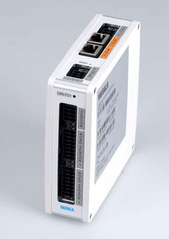
275
Inputs and outputs Operating voltage 9 … 32 V DC Average power consumption With two DRS511 sensors 0.76 W With two FP2000 sensors 1.06 W Compliance EU directives and regulations EMC Directive (2014/30/EU) RoHS Directive (2011/65/EU) amended by 2015/863 EMC immunity EN 61326 1, industrial environment FCC part 15, class B ICES 3 (B) EMC emissions CISPR 32 / EN 55032, Class B Electrical safety EN 61010 1 Dry heat IEC 60068 2 2 Vibration IEC 60068 2 6 Shock IEC 60068 2 27 Rough handling IEC 60068 2 31 Damp heat IEC 60068 2 78 Compliance marks CE, FCC, ICES, RCM Mechanical specifications Dimensions (H × W × D) 126 × 37 × 127 mm (5.0 × 1.5 × 5.0 in) Weight 0.3 kg (0.7 lb) Materials Screws, washers Stainless steel AISI 316 DIN rail locking piece Stainless steel AISI 630 Frame profile Aluminum EN AW 6060 T6 Side plates Plastic PC/ABS
Spare parts and accessories
Technical data Operating environment Operating temperature −40 … +60 °C (−40 … +140 °F) Storage temperature −60 … +80 °C (−76 … +176 °F) Operating humidity 5 … 95 %RH, non condensing
Spare part or accessory Order code DRI701 with: • Power cable 30 cm (11.81 in) • Ethernet cable 30 cm (11.81 in) DRI701SP Phoenix Contact DFMC 8 pin cable connector set (10 pcs) 262923 Phoenix Contact DFMC 16 pin cable connector set (10 pcs) 262925 Insulated ferrules 0.5 mm2, length 10 mm, white (100 pcs) 237754SP Supported sensors Road state sensors, embedded 2 × DRS511 / 2 × FP2000 1) Subsurface temperature sensors 2 × DTS12G / 2 × DTS210 2) Global radiation sensor For example, SP Lite2 3) 1)For FP2000 availability, contact Vaisala. 2)DTS210 only in retrofit installations. 3)The first DRI701 supports one global radiation sensor and one subsurface temperature sensor or two subsurface temperature sensors. www.vaisala.com
DRS511 is embedded directly in the pavement. It gathers its readings by being installed flush with the surface. The sensor design features open end carbon fiber electrodes and optical fiber technology. These are molded into a solid sensor block consisting of an epoxy compound with properties matching the surface for thermal conductivity and emissivity.
Chemical knowledge A characteristic that is unique to DRS511 compared to all other embedded road and runway sensors is its ability to provide a calculation of the amount of chemical on the sensor’s surface. The value is provided in the form of g/m2 and lb/mi2, which is a very effective way to determine how chemicals will perform if additional moisture is introduced. The greater the quantity of chemical present, the better the chance of the surface remaining unfrozen with the introduction of more ice or snow. In addition to providing the amount of chemical present, DRS511 also calculates the freezing point of the current solution as another decision point used by many winter maintenance decision makers.
The sensor contains 2 Pt100 elements to measure the temperature of the road or runway surface. Temperature is a key decision factor for the formation of ice and snow on the pavement, and is used before an event to determine if snow or ice will stick to the surface.
276
The surface temperature is also key to determining how effective winter maintenance chemicals will work at the desired temperature, as air temperature can be many degrees different and is not a good decision point for determining chemical effectiveness. Lastly, the surface temperature, when used with dew point, can accurately indicate when hoar frost formation is possible.
Without the weather stations' algorithm to process the readings, DRS511 provides only the surface temperature of the road or runway.
Surface state DRS511 not only provides the temperature of the pavement, but it also detects the presence of moisture on the pavement. Using these readings, the Vaisala road weather station algorithm produces the road state such as dry, wet, ice, and snow to give you an estimate of surface conditions on the roadway or Whenrunway.used in Vaisala Road Weather Station RWS200, DRS511 also shows the sky condition: is it raining or not, are there clouds or not.
DRS511 is a passive sensor, which means that it does not change or alter the environment that it resides in. This type of road and runway technology has been around for decades, so when using DRS511 the risk of failure or ineffectiveness in your operations is minimal. The passive technology found in the sensor has been tested by institutions and authorities for years, so you know exactly how the sensor can aid you in your operational decision making.
Tried and true DRS511 offers many advantages as a surface sensor system, with the biggest being its location. It is placed directly where the tires of vehicles and aircraft interact with the surface of the road or runway. This means it is directly measuring its environment, which ensures accuracy.
DRS511 Embedded Road and Runway Sensor Features •Amount of de icing chemical measurement • Identifies road condition •Water amount measurement •Surface •Subsurfacemeasurementtemperaturetemperaturemeasurement−6cm(−2.36 in) •Freezing point •Hoar frost detection
Surface temperature
Vaisala DRS511 is an embedded road and runway sensor that takes a variety of measurements and observations of the road or runway surface. It is used in a road weather station to provide accurate and reliable information on the surface state.
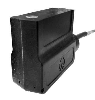
Pt100 accuracy ±(0.1 + 0.00167 × temperature) °C Water layer thickness 1) Observation range 0 … 7 mm (0 … 0.28 in) Accuracy 0.1 mm in the range of 0 … 1.0 mm 2) Reported surface states 1)
Operating environment
3)Requires dew point information.
1) When connected to a Vaisala weather station.
Vaisala classes Dry, Moist, Wet, Snowy, Icy, Frosty 3) Moist and chemical, Wet and chemical EN 15518 3 classes Dry, Moist, Wet, Streaming water, Slippery Sky condition No rain, Rain, Cloudy, Clear
Cable length options 20 m (65 ft 7 in) 30 m (98 ft 5 in) 50 m (164 ft 1 in) 100 m (328 ft 1 in) 150 m (492 ft 2 in) 200 m (656 ft 2 in) 250 m (656 ft 2 in) 300 m (984 ft 3 in)
1)To make sure that the sensor remains even with the road surface, the sensor can wear up to 35 mm (1.38 in).
Mechanical specifications
www.vaisala.com 277
Surface temperature and temperature at 6 cm (2.36 in) below the surface 1) Observation range −40 … +60 °C (−40 … +140 °F)
Dimensions (H × W × D) 1) DRS511AB: 75 × 84 × 30 mm, bottom 38 mm (2.95 × 3.31 × 1.18 in, bottom 1.50 DRS511BBin) for bridge applications: 50 × 84 × 30 mm, bottom 38 mm (1.97 × 3.31 × 1.18 in, bottom 1.50 in)
Materials
Measurement
Operating temperature −40 … +60 °C (−40 … +140 °F) EU directives and regulations EMC Directive (2014/30/EU) 1) RoHS Directive (2011/65/EU) amended by 2015/863 1) EMC immunity EN 61326 1, industrial environment 1) EMC emissions CISPR 22 / EN 55022, Class B 1)
1)Temperature at −6 cm (−2.36 in), water layer thickness, and surface state are only available when DRS511 is used with a Vaisala road weather station. 2)Applies to an even layer of water on the sensor. The detection accuracy of the average water layer thickness on the road depends on sensor installation, pavement material, and water impurities.
Temperature sensors 2 Pt100 elements at 0 cm (0 in) and −6 cm (−2.36 in) from the surface 1/3 IEC 751 Class B
Technical data
Chemicals Supported de icing chemicalsSodium chloride (NaCl), calcium chloride (CaCl2), sodium acetate (NaOOC2H3), potassium formate (KOOCH), magnesium chloride (MgCl)
Type V extension cable optionMaximum 1524 m (5000 ft) Weight including 50 m (165 ft 1 in) cable 3.1 kg (6.8 lb)
Epoxy compound Araldite D, HY 956, lamp black for color Cable tubing Stainless steel AISI 316L Cable 4 × (2 × 0.22 mm2 / 24 AWG and shield) PUR, high density polyethylene lead isolation Sensing electrodes Carbon fiber in epoxy Optical sensor Acrylic optical fibers
performance
•Can operate standalone, as a standalone solution with DST111, or as a sensor in a road weather Comparedstation to its predecessor DSC111, DSC211 offers the following:
•Enhanced autocalibration
Improved sensitivity for earlier warnings
•Accuratesnowand
Optional measurementvisibility
Frost detection and enhanced autocalibration
DSC211 is the latest member of the DSC family with more sensitive measurement of the amount of water, ice, or snow on the road. Also, the improved autocalibration provides long-term stability by better adapting to the wear and tear of the road surface. 278
•Improved accuracy and sensitivity of the measurement of the amount of water, ice, or snow
For the most accurate and reliable observations, Vaisala recommends using DSC211 as a sensor in the Vaisala RWS200 or RWCC road weather station. RWS200 and RWCC automatically reports observation values from the most reliable sensor in the system, for example, air temperature and relative humidity from Vaisala HUMICAPâ Humidity and Temperature Probe WithHMP155.certain limitations, DSC211 can be connected to Vaisala legacy road weather stations LX RPU and ROSA.
Because DSC111 and DSC211 share the same hardware, you can usually upgrade your DSC111 to DSC211 just by purchasing the software. To make sure that your system configuration is compatible with DSC211, please contact Vaisala.
The spectroscopic measuring principle enables accurate measurement of the amount of water, ice, or snow on the road surface. In addition, DSC211 provides road state and grip, which is a calculated estimate of friction.
DSC211 has a clearly improved sensitivity and accuracy compared to DSC111. It provides an accurate measurement of the presence of ice crystals well before they make the road slippery. The earlier warnings enable the winter maintenance engineer to react before the road becomes hazardous for drivers.
Features
The remote sensor DSC211 eliminates the tra c disruption caused by installation and maintenance. Remote installation means that there is no need to cut the road surface or to close the road. The sensor can be installed in a remote location to a pole adjacent to the road, or as an addition to Vaisala Road Weather Station RWS200.
The optional visibility measurement offers a useful, compact, and extremely cost-effective way to measure the meteorological optical range (MOR). The visibility measurement extends the capabilities of DSC211 to detect low visibility conditions – without any external hardware. Upgrade from DSC111 to DSC211
DSC211 Remote Road State Sensor
•Measures the amount of water, ice, or snow on the road or runway surface • Provides road state and grip based on the amount of water, ice, or measurementsreliableevenwith intense tra •Easycand low-cost installation and maintenance since there is no need for tra c control
No traffic disruption for installation or maintenance
DSC211 requires air temperature, relative humidity, and road temperature observations from another sensor or system for frost detection and enhanced autocalibration. DSC211 can be connected to Vaisala Remote Road Temperature Sensor DST111, which provides these observations to DSC211.
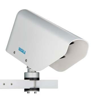
Inputs and outputs Connectors 3 × M12 (5 pins) RS 485 and power out for DST111, RSfemale485 and power in, male RS 232, male Communication interface RS 485 isolated, RS 232 Sensor support DST111 Input voltage 9 … 30 V DC Maximum input current 0.25 A at 24 V
Installation angle from the horizontal line 30 … 80° (35 … 65° recommended)
Measuring distance with visibility observation disabled 2 … 15 m (6 ft 7 in … 49 ft 3 in)
Operating environment Operating temperature −40 … +60 °C (−40 … +140 °F) Storage temperature −55 … +60 °C (−67 … +140 °F) Operating humidity 0 … 100 %RH IP rating IP65 Compliance EU directives and regulations Low Voltage Directive (2014/35/EU) EMC Directive (2014/30/EU) RoHS Directive (2011/65/EU) amended by 2015/863
Measuring distance with visibility observation enabled 8 … 15 m (26 ft 3 in … 49 ft 3 in)
Diameter of measuring area at 10 m (33 ft) 20 cm (7.87 in) Surface layer thickness Water 0.00 … 2 mm (0.00 … 0.06 in) Ice 0.00 … 2 mm (0.00 … 0.06 in) Snow 0.00 … 10 mm (0.00 … 0.40 in) Snow (water equivalent) 0.00 … 1 mm (0.00 … 0.04 in) Accuracy, water and ice ±0.1 mm in the range of 0 … 1 mm (0 … 0.04 in)
EMC immunity EN 61326 1, industrial environment FCC part 15, class B ICES 3 (B)
Measurement performance
Date and time Real-time clock with battery backup Settling time before dry calibration5 min Typical power consumption At above −10 °C (+14 °F) 1.13 W at 24 V At below −10 °C (+14 °F) 1.90 W at 24 V With lens heating on 5.25 W at 24 V
EMC emissions CISPR 32 / EN 55032, Class B Eye safety IEC 60825 1:2014 Class 1 laser product Vibration IEC 60068 2 6
279
DSC211 technical data
Mechanical specifications
Dimensions (H × W × D) 210 × 133 × 448 mm (8.27 × 5.24 × 17.64 in) Weight Sensor: 2.69 kg (5.93 lb) Mounting bracket: 0.71 kg (1.57 lb)
Mounting Fits on a sensor support arm with cross-section of 40 × 40 mm (1.57 × 1.57 in)
Cables 3 … 150 m (9 ft 10 in … 492 ft) One end without connector 0.6 m (1 ft 12 in) extension cable to DST111 Materials Weather shield ABS plastic Transmitter body POM plastic Bolts, screws, and washers Fixture plate of the weather shield Stainless steel Lenses and windows Glass Other parts Aluminum Vaisala Remote Road Temperature Sensor DST111 presented with Vaisala Remote Road State Sensor DSC211 www.vaisala.com
Grip Reported level of grip 0.09 … 0.82 Reported surface states Vaisala classes Dry, moist, wet, frosty 1), snowy, icy, slushy EN 15518 3 classes Dry, moist, wet, streaming water, slippery Visibility (optional) Observation range (meteorological optical range, MOR) 10 … 2000 m (33 … 6572 ft) Resolution 1 m (3 ft 3 in) Accuracy (fog and snowfall) ±20 % (average) Response time 60 s 1)Frost is only reported when dew point and road temperature information is available.
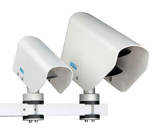
No traffic disruption for installation or maintenance
The optional visibility measurement offers a useful, compact, and extremely cost-effective way to measure the meteorological optical range (MOR). The visibility measurement extends the capabilities of DSC111 to detect low visibility conditions – without any external hardware.
sensors can be directly connected to DSC111 to provide, for example, road and air temperature, relative humidity, and present weather.
DSC111 Remote Road Surface State Sensor Features •Remote surface state sensing •Spectroscopic measuring principle individually identifies the presence of water, ice, snow, and •Providesfrost road state and grip •Accurate and measurementsreliableevenwith intense tra •Easycand low-cost installation and maintenance since there is no need for tra c control • Cost-effective visibility •Weather-proof,measurement durable design
DSC111 provides an accurate measurement of the presence of ice crystals well before they make the road slippery. The early warnings enable the winter maintenance engineer to react before the road becomes hazardous for Additionaldrivers.
The spectroscopic measuring principle enables accurate measurement of the amount of water, ice, or snow on the road or runway surface. In addition, DSC111 provides road state and grip, which is a calculated estimate of friction.
Accurate measurements
The remote sensor DSC111 eliminates the service disruption caused by installation and maintenance. Remote installation means that there is no need to cut the road surface or to close the road. The sensor can be installed in a remote location to a pole adjacent to the road, or as an addition to a Vaisala Road Weather Station.
Optional measurementvisibility
Compatibility DSC111 can be used as a standalone sensor or as a sensor in LX-RPU or ROSA, but it is not compatible with RWS200. In RWS200, you can use DSC211 which has improved accuracy and sensitivity compared to DSC111. For more information on the DSC211 features, see the DSC211 datasheet.
DSC111 has proven its capabilities during intensive field testing in collaboration with Vaisala customers. The sensor is operational at hundreds of sites throughout the world. 280
Measurement performance
Mechanical specifications
EMC emissions CISPR 32 / EN 55032, Class B Eye safety IEC 60825 1:2014 Class 1 laser product Vibration IEC 60068 2 6
Installation angle from the horizontal line 30 … 80° (35 … 65° recommended) Diameter of measuring area at 10 m (33 ft) 20 cm (7.87 in) Surface layer thickness Water 0.00 … 2 mm (0.00 … 0.06 in) Ice 0.00 … 2 mm (0.00 … 0.06 in) Snow 0.00 … 10 mm (0.00 … 0.40 in) Snow (water equivalent) 0.00 … 1 mm (0.00 … 0.04 in)
Operating environment Operating temperature Storage IPOperatingtemperaturehumidityrating −40 … +60 °C (−40 … +140 °F) −55 … +60 °C (−67 … +140 °F) 0 … 100 %RH IP65
Input voltage 9 … 30 V DC Maximum input current 0.25 A at 24 V Date and time Real-time clock with battery backup Settling time before dry calibration5 min
Measuring distance with visibility observation disabled 2 … 15 m (6 ft 7 in … 49 ft 3 in) Measuring distance with visibility observation enabled 8 … 15 m (26 ft 3 in … 49 ft 3 in)
Optical specification Light source Near-infrared laser diodes Detection of window contaminationContamination level of the receiver window is measured
Radiation properties of incorporated laser diodes Beam divergence 0.022 radians Pulse duration 0.55 ms Maximum output Compliance EU directives and regulations 0.0077 W Low Voltage Directive (2014/35/EU)
Observation range (meteorological optical range, MOR) 10 … 2000 m (33 … 6572 ft)
EMC Directive (2014/30/EU) RoHS Directive (2011/65/EU) amended by 2015/863
Optics and radiation
Typical power consumption At above −10 °C (+14 °F) 1.13 W at 24 V At below −10 °C (+14 °F) 1.90 W at 24 V With lens heating on 5.25 W at 24 V
1)Frost is only reported when dew point and road temperature information is available.
Radiation properties Beam divergence 0.022 radians Pulse duration 0.55 ms Maximum output 0.0077 W
EMC immunity EN 61326 1, industrial environment FCC part 15, class B ICES 3 (B)
Dimensions (H × W × D) 210 × 133 × 448 mm (8.27 × 5.24 × 17.64 in) Weight Sensor: 2.69 kg (5.93 lb) Mounting bracket: 0.71 kg (1.57 lb) Mounting Fits on a sensor support arm with cross-section of 40 × 40 mm (1.57 × 1.57 in)
Technical data
Grip Reported level of grip 0.09 … 0.82 Reported surface states Vaisala classes Dry, moist, wet, frosty , snowy, icy, slushy Visibility (optional)
Cables 3 … 150 m (9 ft 10 in … 492 ft) One end without connector 0.6 m (1 ft 12 in) extension cable to DST111 Materials Weather shield ABS plastic Transmitter body POM plastic Bolts, screws, and washers Fixture plate of the weather shield Stainless steel Lenses and windows Glass Other parts Aluminum 281
Inputs and outputs Connectors 3 × M12 (5 pins) RS 485 and power out for DST111, RSfemale485 and power in, male RS 232, male Communication interface RS 485 isolated, RS 232 Sensor support DST111, PWD22,PWD10/PWD12/PWD20/WXT530,HMP155
Resolution 1 m (3 ft 3 in) Accuracy (fog and snowfall) ±20 % (average) Response time 60 s
www.vaisala.com Remote Road Surface Temperature DST111 presented with Remote Road Surface State Sensor DSC111 282
Sensor Features •Remote •Eliminatesmeasurementtemperaturethetraditionalnighttimeproblemoftoo cold road temperature readings when the sky is clear •No need for road specific emissivity adjustment •Easy and low-cost installation and •Nomaintenanceinternalmoving parts •Stable measurement results even with intense tra c •Weather-proof, durable design •Reports air temperature and •Easyhumidityintegration with Vaisala Road Weather Station RWS200
DST111 can also be installed alongside an existing Vaisala RWS200 or the earlier ROSA or LX RPU Road Weather Stations.
Reliable measurementsinfrared
The DST111 data also enables DSC111 and DSC211 to report frost, and it improves their autocalibration, impacting longterm stability.
DST111 Surface Temperature
Great combination with DSC111 or DSC211 DST111 can be combined with Vaisala Remote Road State Sensor DSC111 or DSC211. This combination provides all key parameters for road weather, such as road temperature, road state, and grip.
DST111 provides reliable results in conditions where most of the commercially available infrared sensors fail. At nighttime, when the road surface is cooling under a clear sky, conventional infrared sensors provide an error of up to −3 °C due to emissivity conditions of the road surface. DST111 compensates for this error by using wavelengths where mirrored radiation is not visible. This also eliminates the need for road specific emissivity adjustment. No traffic disruption for installation or maintenance Installation of DST111 is easy, requiring no slot cutting or road closure. Supplied with solar/GSM options, the sensor is ideal for standalone operation in remote or in fill locations and on bridge decks.
The sensor is simply installed on a mast or an existing structure beside the road.
DST111 provides a unique remote alternative to measuring road surface temperature. By measuring the infrared radiation emitted by the surface and applying intelligent signal processing, the sensor provides a reliable remote surface temperature measurement. 283
Remote
Measuring distance 2 … 15 m (6 ft 7 in … 49 ft) Installation angle from the horizontal line 30 … 85° (35 … 65° recommended) Measuring area Ø 150 cm at 10 m (59.1 in at 32 ft)
1)The relative humidity, air temperature, and dew point readings of HMP60 are mainly intended for internal compensation of DST111. The accuracy is not as high as that of the HMP155 sensor with a proper solar radiation shield.
Measurement performance
1)The RMS (root mean square) error of the surface temperature reading is 0.3 °C in typical freezing conditions when compared to a reference thermometer installed on the road surface. This accuracy is valid when the difference between the device temperature and the surface temperature is less than 10 °C and the device temperature is in the range of -40 … +40 °C. (In the range of +40 … +60 °C the error may be increased by an offset of ±1.5 °C.)
HMP60 measurement performance
Time constant 1 min Data refresh time 30 s
Compliance EU directives and regulations EMC Directive (2014/30/EU) RoHS Directive (2011/65/EU) amended by 2015/863 EMC compatibility EN 61326 1, industrial environment FCC part 15, class B ICES 3 (B) Vibration IEC 60068 2 6, Level 2 g Inputs and outputs Input voltage 9 … 30 V DC Average input current 1.4 mA at 24 V Average power consumption 0.05 W at 24 V Communication interface Isolated RS 485 Connectors Male M12 (5 pins) including RS 485 and power in Cable connector Ø 15 mm (0.59 in) Cables 3 … 150 m (9 ft 10 in … 492 ft) 1) One end without connector 0.6 m (1 ft 12 in) extension cable to DSC111 or DSC211
Technical data
Road temperature Observation range −40 … +60 °C (−40 … +140 °F) Resolution 0.1 °C Accuracy (RMS error 1)) 0.3 °C (0.5 °F)
1) Cables longer than 50 m (164 ft) require a minimum of 24 V input. Operating environment Operating temperature −40 … +60 °C (−40 … +140 °F) Storage temperature −55 … +60 °C (−67 … +140 °F) Operating humidity 0 … 100 %RH IP rating IP65 Mechanical specifications Dimensions (H × W × D) 125 × 100 × 320 mm (4 92 × 3.94 × 12.60 in) Weight 1.9 kg (4 19 lb) Mounting Fits on a support arm with crosssection of 40 × 40 mm (1.57 × 1.57 in) Materials Cover ABS plastic Mounting bracket POM C Other parts Aluminum Remote Road Temperature Sensor DST111 with Remote Road State Sensor DSC211 www.vaisala.com 284
Relative humidity 1) Measurement range 0 … 100 %RH Resolution 0.1 %RH Typical accuracy at +20 °C (+68 °F)±3 %RH (0 … 90 %RH) ±5 %RH (90 … 100 %RH) Air temperature 1) Measurement range −40 … +60 °C (−40 … +140 °F) Resolution 0.1 °C Typical accuracy at +20 °C (+68 °F)±0.6 °C (±1.1 °F) Dew point temperature 1) Measurement range −40 … +60 °C (−40 … +140 °F)
Subsurface Temperature Sensor DTS12G DTS12G is specially designed for automatic weather stations. It can be used to measure the temperature at a certain level beneath the surface. In roads applications, DTS12G is typically used to measure road depth temperature information at 30 cm (11.81 in) below the surface. This information is used to produce a 24 hour road surface temperature forecast. DTS12G for subsurface temperature measurement
Air Temperature Sensor DTS12A DTS12A is meant to be used in meteorological temperature measurement. Vaisala recommends using a radiation shield to ensure correct results. 285
•
DTS12 sensors can be used with equipment operating either with the resistor bridge principle (3 wire connection) or constant current principle (4 wire connection). The housing of the platinum resistance (Pt100 sensor) sensing element is made of stainless steel, and it is located in the tip part of the assembly. The cable screen attached to the sensor housing provides a good shield against electromagnetic interference (EMI).
Water Temperature Sensor DTS12W DTS12W is dedicated for measuring water temperature in tanks. It is equipped with the standard M20 thread for fastening. DTS12W for water temperature measurement
•EMI
DTS12 Series temperature sensors are specially designed for outdoor use, for example with weather stations. The watertight, weather-resistant design ensures reliable temperature measurements in extreme conditions.
Air Temperature Sensor DTS12A for meteorological temperature measurement resistance element 1/4 EN 60751 Class B Weather-resistant design shielding
Features •Platinum
DTS12 Series Temperature Sensors
•Accuracy:
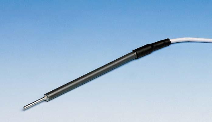
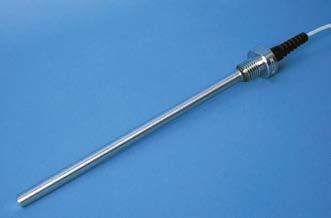
Sensing element Platinum resistance element (Pt100)
Technical data
[0.13] Ø
[0.31] [0.98][0.98]2525 [0.94]24270[10.63] 28 [1.10] Ø
Specifications
Housing material Stainless steel AISI 316 Probe Max. diameter: 9.5 mm (0.37 in) Length: 100 mm (3.94 in) Cable Screened multicore 4 × 0.22 mm (24 AWG) and shield Diameter: 5 mm (0.20 in)
Ø
[0.37] [3.94]100 Ø
Accuracy 1/4 EN 60751 Class B ±0.08 °C at 0 °C (+32 °F) Sensitivity 0.385 Ω/°C Measurement range −80 … +80 °C (−112 … +176 °F)
Sensor Platinum resistance element (Pt100) Accuracy 1/4 EN 60751 Class B ±0.08 °C at 0 °C (+32 °F) Sensitivity 0.385 Ω/°C Measurement range −60 … +80 °C (−76 … +176 °F)
[6.81]173 Ø
Sensor Platinum resistance element (Pt100) Accuracy 1/4 EN 60751 Class B ±0 08 °C at 0 °C (+32 °F) Sensitivity 0 385 Ω/°C Measurement range −80 … +80 °C (−112 … +176 °F)
Specifications
Specifications
Cable length options 10 m (32 ft 10 in) 20 m (65 ft 7 in) 30 m (98 ft 5 in) 50 m (164 ft 1 in) 100 m (328 ft 1 in) 120 m (393 ft 8 in) 150 m (492 ft 2 in) 200 m (656 ft 2 in) Type V extension cable option Maximum 1524 m (5000 ft)
Housing material Stainless steel AISI 316, PVC Probe Max. diameter: 10 mm (0.39 in) Length: 173 mm (6.81 in)
[0.47] mm[in] Dimensions
Housing material Stainless steel AISI 316 Probe Max. diameter: 33 mm (1.30 in) Length: 270 mm (10.63 in) Tube: 12 mm (0.47 in) Thread: M20 Cable Screened multicore 4 × 0.22 mm2 and Length:shield 5 m (16 ft 5 in) Diameter: 5 mm (0.20 in) DTS12A DTS12G DTS12W 10 [0.39] 13 [0.51] 3.2 9.5 8 12 www.vaisala.com 286
Cable Screened multicore 4 × 0.22 mm and Length:shield 3.5 m (11 ft 6 in) Diameter: 5 mm (0.20 in)
Benefits •Mobile sensor provides pavement data for your entire route
•Inexpensive compared to other pavement monitoring methods
Vaisala Surface Patrol Pavement Temperature Sensor DSP100 Series is a mobile temperature sensor for detecting possible freezing temperatures on the pavement.
DSP100 features a non contact infrared sensor for measuring pavement temperature, and it also measures air temperature. The easy to use DSP100 is valuable for large agencies, such as Departments of Transportation, airport operations, as well as smaller companies with only a few trucks.
Ease of Use DSP100 can be calibrated in the field, ensuring you are always getting the most accurate readings. In addition, the pavement probe features a cone design to protect the sensor from spray and winter elements that can decrease the accuracy of the readings. 287
•Real-time pavement and air temperature readings
•Knowledge of surface pavement temperature makes winter decision making easier Accurate Real-Time Data DSP100 is mounted outside your vehicle and continuously monitors road surface temperatures, providing instant feedback on road surface conditions. DSP100 has a separate air temperature sensor and cabling so that it can be placed away from direct sunlight for accurate Thereadings.dataretrieved from DSP100 is accurate and real time, making it a reliable method for collecting pavement information.
DSP100 Series Surface Patrol Pavement Temperature Sensor Features •Measures both air and pavement •Easy-to-read,temperatures dash-mounted digital •Patenteddisplaycone design to protect sensor •Separatelensair sensor for improved •Quickaccuracyand easy to install •Field calibration with no need to return unit to manufacturer •Integrates with other vehicle equipment such as spreaders •Optional RS-232 output to connect to a computer or analog output for other applications
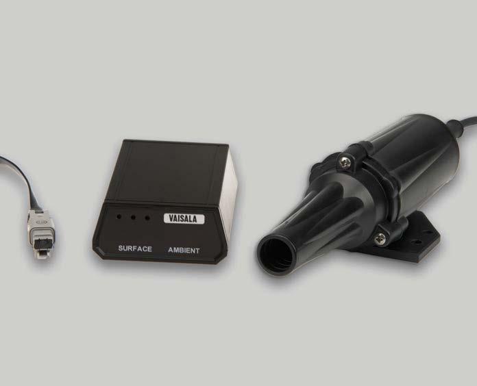
Mechanical Specifications
DSP100 Series Technical Data
Temperature
Housing/Optical assembly Injected molded housing with lens protecting cone Optics Precision crystal (germanium lens) Display Unit Dimensions (H × W × L) 50.8 × 88.9 × 139.7 mm (2.00 × 3.50 × 5.50 in) indicators User selectable audio and visual temperature indicators digital meter High-brightness red LED, showing both ambient air and pavement temperature Spreader Control Dimensions (H × W × L) 36.0 × 117.6 × 133.0 mm (1.42 × 4.63 × 5.24 in)
Other fleet
Runway temperature monitoring for airport operations DSP100 Series Products DSP110 Surface Patrol with display DSP111 Surface Patrol with display and digital output DSP112 Surface Patrol with display and analog output DSP113 Surface Patrol with spreader interface and DB9 connector DSP114 Surface Patrol with spreader interface and FA connector www.vaisala.com 288
Measurement units °C or °F (user selectable)
Dual
Winter
DSP110,
Accuracy of surface temperature 1) 2) ±0.28 °C at 0 °C (±0.5 °F at +32 °F) Field calibration Adjustable ±2.8 °C at 0 °C (±5.0 °F at +32 °F)
Cable length, both sensors 5.5 m (18 ft) standard Infrared Surface Temperature Sensor Weight 57 g (2.01 oz) Weight, with cables and connectors284 g (10.02 oz)
Measurement Performance
1)For DSP111: EN 61000-4-6 Conducted RF immunity test specification within EN 61326-1:2013 is 3 Vemf. Within frequency range 15 ... 30 MHz, DSP111 may invalidate RS-232 output message with levels above 2 Vemf. 2)For DSP113: EN 61000-4-3 Electromagnetic RF immunity test specification within EN 61326-1:2013 is 3 V/m. Within frequency ranges 80 ... 200 MHz, 750 MHz, and 1600 MHz, DSP113 may show ± 1.2 C deviation in surface temperature readings with levels above 1 V/m. EN 61000-4-6 Conducted RF immunity test specification within EN 61326-1:2013 is 3 Vemf. Within frequency ranges 2.4 ... 60 MHz, DSP113 may show invalid ambient temperature readings with levels above 1 Vemf.
Inputs and Outputs
Operating Environment Operating temperature −40 … +71 °C (−40 … +160 °F) Storage temperature −40 … +71 °C (−40 … +160 °F)
Compliance CE compliance (product models DSP111, DSP113) Directive 2014/30/EU EMC standard EN61326-1, immunity test requirements for equipment intended to be used in a basic electromagnetic environment Shock 50 Gs Vibration 10 Gs in any axis Applications maintenance operations (snow plows, supervisor vehicles, and so on) vehicles to increase your AVL network
Input voltage 12 or 24 VDC unregulated Digital output (optional) RS-232; ASCII output Analog output (optional) 4 … 20 mA; 1 … 5 V Connections Compression terminals for input voltage and signals quick disconnect connector for sensor head
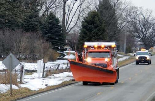

Thunderstorm Manager Features
•Proven best quality data
•Lightning Threat Zone – a one hour forecast of the potential for lightning and severe weather (in 10 minute increments). Includes a storm trajectory display, and a storm cell velocity vector with speed and direction.
•Storm Intensity – displays current lightning threat region, and the storm intensity level
•Accessbrowserdatafor anywhere •Available to you now
•Storm track – showing history of the storm route
•Global oceanic and continental coverage Storm tracking
Alerts Independent of the display, alerts are working in the background and are Multipleserver-based.alertareas per site have different types of notifications (for example, Information, Warning, and Alarm) depending on the distance to the Alertsite.
Vaisala Thunderstorm Manager enables you to track approaching storms in realtime. You can use a desktop or mobile device browser to access the displays.
One or multiple sites with alerting rings, defining an alert region, will serve to notify you about lightning taking place in the area. Quality lightning data Thunderstorm Manager is powered by lightning from the Vaisala global lightning detection network, GLD360, and lightning from the Vaisala US National Lightning Detection Network, NLDN. Both networks are proven industry leaders, delivering excellent detection e ciency, location accuracy, and distinction between cloud and cloud-to-ground lightning.
notifications can be received via email and SMS, including all-clear notices. 289
Benefits •Easy access using any modern web
Vaisala Thunderstorm Manager 1.2 is a professional thunderstorm tracking and alert management application and indicates the possibility of severe weather Vaisala Thunderstorm Manager is a web based application to assist you in tracking approaching storms. It supports a broad range of applications from synoptic or national scale lightning surveillance, to keeping local ground and maintenance crews safe, and operational stoppages at a minimum.
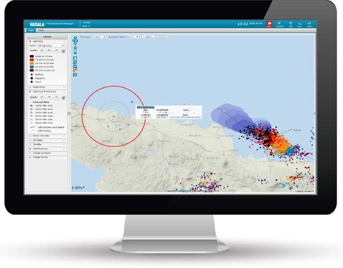
•Hover
•Zoomcursorand
•Toggle
•7
•Standardsite
•Time
•AlertsSMS
• Display
General features •Map
•Choice
Animation features
•Choose from multiple time periods (from ½ hour up to 24 hours), from present time to 7 day history various replay speeds www.vaisala.com
290
•Alert
•Measureinformationdistance
Additional features display for both cloud-toground and cloud-to-cloud lightning updates every 30 seconds of lightning polarity and graphical representation of the magnitude of each strike discrimination of lightning to determine the storm path through color-coded symbols of coordinates that follow the pan with dedicated zoom area selection over lightning events for display of more detailed between 2 points (for example, between strike location and asset) day and night modes
Alert features alert site standard, but more sites can be added for extra to 3 levels of alert per alert alert regions are circles, but customers can define polygons for an extra charge of alert-triggering criteria (for example, one or more lightning events, cloud and/or cloud-to-ground lightning) day alert history notifications to email and to multiple email addresses or cell phone numbers clear alert notifications when no lightning has occurred after a predetermined amount of time.
•Display
•Choose
•One
•Addchargeup
•All
No device pairing is needed because the devices are associated with a specific cloud account when they are purchased.
Vaisala sensors that you can connect to Wx Beacon currently include Vaisala Air Quality Transmitter AQT530 and Vaisala Weather Transmitter WXT530.
The measurement data in Vaisala Wx Beacon is updated once a minute. The data is available 24/7. Data visualization and export
Wx Beacon has a dashboard-like summary view, showing the different measurements coming from the sensors.
Vaisala Wx Beacon is cloud software for accessing measurement data from Vaisala sensors. With Wx Beacon, you can easily manage your devices and their settings and monitor observations in real time. Measurement data can be downloaded to other applications for further analysis.
Features •Online service for monitoring measurement parameters •Up-to-date •Access•Availablemeasurementreal-timedata24/7withwebbrowser on computer, tablet, or mobile phone •Dashboard-like measurement •Historysummarydata as graphs or in tables •Data export to CSV format •Device management •Open API for data integration •Data from Vaisala Beacon Station BWS500 through Vaisala Edge Gateway EGW501
Real-time measurement data
Vaisala Beacon Edge Gateway EGW501 of a Vaisala Beacon Station BWS500 handles the data transfer between the sensors and Vaisala Wx Beacon.
Centralized managementdevice
The table view shows all measurement parameters of one of more devices for the selected timeframe, and you can filter the data to be shown from one minute to up to one day. From the table view, you can export the data in CSV format, for example, for viewing in Excel.
Wx Beacon not only provides a UI, but in addition you can transfer the data to your own data collection system through the Vaisala Wx Beacon open API.
Wx Beacon includes settings for managing your API integrations. 291
There are settings for the unit conversion so you can select, for example, whether to display the wind speed measurements in m/s, mph, or knots. Data integration to systems
In the graph view, you can compare two measurement parameters of a device and limit the timeframe from one day to up to one year.
The summary shows data from the most recent 24-hour time period.
Wx Beacon helps you manage your devices. You can show and hide devices and modify their settings, such as the device name. The system raises alerts and notifications in case a sensor needs maintenance or there is some other significant event.
In addition to real-time data, Wx Beacon shows the history data. There are different views available with various filtering options. You can look at each device and measurement parameter separately or combine several devices, measurement parameters, and measurements to one view.

Measurement parameters 1) •Air temperature, relative humidity, air pressure, wind speed, maximum wind speed, wind direction, rain accumulation, rain •NOintensity 2, NO, O3, CO, PM1, PM2,5, PM10 •CO2 Units available •Air pressure: hPa, mbar, inHg •Air temperature: °C, °F •Relative humidity: %RH •Rain accumulation: mm, in •Rain intensity: mm/h, in/h •Wind direction: ° •Wind speed: m/s, mph, knots •Maximum wind speed: m/s, mph, •Gasknotsconcentration: ppb, ppm, µg/m3
2)Wx Beacon login credentials required. User interface Measurement views Summary, graph, table Download file format Max.CSV latest 1 month data or 60.000 measurements User interface languages English, Finnish www.vaisala.com 292
Reported values Instant or average, depending on the measurement parameter Measurement interval 1 minute Reporting interval 1 minute 1)Depend on the selected sensors. Connection specifications Web address wxbeacon.vaisala.com Security protocol TLS/SSL Supported browsers Any modern browser, such as Microsoftâ Edgeâ, Google Chrome , Appleâ Safari , Mozilla Firefoxâ Supported environments PC/Mac, tablet, mobile phone Supported sensors •Vaisala Air Quality Transmitter •VaisalaAQT530Weather Transmitter WXT530 Supported devices EGW501 1) Connection capacity No limit Data interface Vaisala Wx Beacon XML API API wxbeacon.vaisala.com/api/xml 2) API description See dita/map?aton_code=M21263docs.vaisala.com/access/sources/9EN 1) For transfer of data from sensor to Wx Beacon.
Technical data Measurements and observations

Pavement preservation RoadAI quickly and accurately assesses pavement conditions up to four times faster than in a manual road survey. It distinguishes between all defect types and provides information and analysis of pavement defects and patches across more than 20 different categories, reporting on every 10 meter segment.
Objective visibility of network condition RoadAI combines geospatial videos, driver-made annotations, and computer vision analysis to support road maintenance and management. Videos, and therefore road condition and surface data, are constantly being updated, enabling engineering teams to make decisions based on the current condition of the network. Data and videos can be shared between teams for a variety of purposes, saving time spent on unnecessary site visits.
RoadAI Features •Online service supporting you with tra c sign inventory management, road marking condition assessment, and road surface condition scoring •Combines live road video, AI for advanced analysis of the video data, and •Assists•Exports•Easy-to-useanalyticssmartphoneapplicationforvideodatacollectionwithautomaticuploadstoRoadAIclouddatatoanassetmanagementsystemorGeographicInformationSystem(GIS)forfurtheranalysisinprioritizingandoptimizingroadmaintenanceprojectsandbudgets
Vaisala RoadAI is a SaaS solution that helps you assess and monitor your road network. RoadAI combines an artificial intelligence (AI) tool with video data and analysis methodology to identify pavement defects and the condition of traffic signs and lane markings, and enables data-driven decision making and efficient deployment of the maintenance patrolling fleet.
Increased efficiency and safety With RoadAI, the patrolling teams can record a variety of on-site issues with the integrated steering wheel button, while video collection happens in the background. This means that unnecessary stops can be avoided, bringing higher e ciency but also increasing safety, with the road inspector not having to step out of the vehicle. Same-day delivery of videos enables teams to respond to public surface condition reports from within the o ce without visiting a site.
Road repair and resurfacing schemes can be planned in reduced time with up-todate road surface condition and defect data available whenever it is needed.
Linking data collection to existing road inspection schedules unlocks a variety of cost-effective pavement preservation strategies. Road assets RoadAI's computer vision technology goes beyond pavement defects. With tra c sign detection and management tools and lane marking condition assessment, it provides improved management of kerb-to-kerb assets. 293
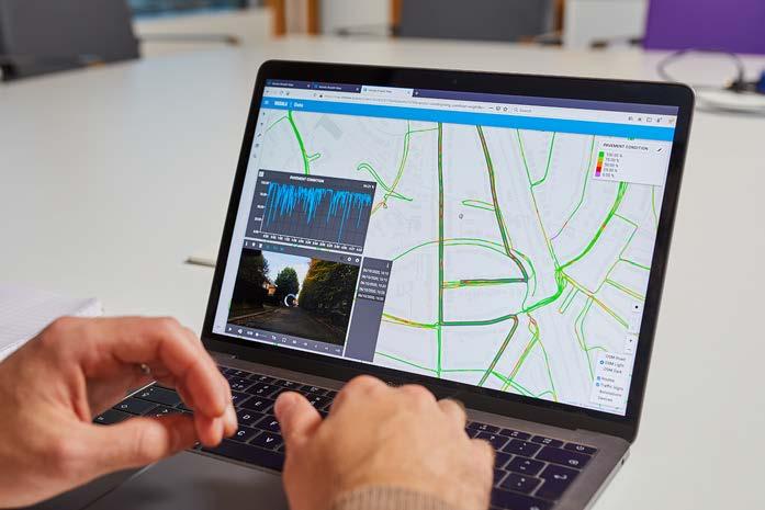
Technical data Web application Web address www.vaisala.com/en/products/road-ai Supported environments PC/Mac, tablet, smartphone Recommended web browsersAny modern and up-to-date browser, such •Googleas: Chrome •Google Chromium™ •Opera•Mozilla Firefoxâ User interface Vaisala RoadAI is a SaaS solution, and new features and user interface languages are added continuously - visit our website for the latest feature and language set. www.vaisala.com 294
•Combines data from fixed and mobile Vaisala sensors and other
•Online service providing real-time data for making data-driven decisions about transportation safety, maintenance, and mobility during winter storm events
Wx Horizon helps you prioritize treatments, plan equipment resources efficiently, and optimize salt and liquid usage to minimize impact to the environment. The data that you can see helps you optimize winter maintenance resources.
•Usessuppliersasecure, cloud-hosted environment that is available 24/7
Wx Horizon helps you prioritize treatments, optimize salt and liquid usage, and plan equipment resources e ciently to minimize the use of resources that can negatively impact the environment. The data that you can see helps you optimize winter maintenance resources. Observation-driven data for better accuracy Wx Horizon combines the best of Vaisala’s accurate, dependable technology with world-class forecasting. It aggregates real-time road data from several sources—including mobile sensors, IoT sensors, RWIS and ESS— then analyzes and visualizes the information. This information provides cities, counties and state and national transportation departments with a clear picture of the current situation so they can take immediate steps to ensure road safety. Designed with mobile sensing in mind Wx Horizon aims to produce the strongest, most e cient solution for helping you keep your roads safer. Beyond research and community input and close collaboration with the public works community, feedback has also been collected from users of the Vaisala Mobile Detector MD30. The result of this research is a solution that has the needs of winter maintenance experts as a fundamental building block to its design. 295
Maintain safer roads Wx Horizon provides you information on the current conditions and precipitation levels and shows near-term forecast data to help you decide when and where to deploy your fleet. The combination of accurate measurements and powerful modeling provides the best situational awareness of current conditions plus a forecast of how the weather will impact road network mobility—giving you the ability to make timely, targeted decisions more easily.
•Leverages Vaisala industryleading sensors and world-class forecasting capabilities
Improve practicesoperationssustainableandtreatment
•Provides road weather condition forecasts using our proprietary road weather model
Wx Horizon Features
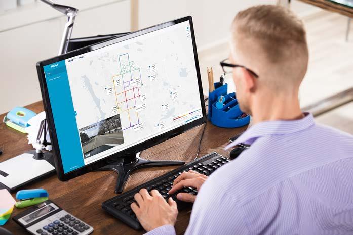
Technical data Web application Web address maintenance/wx-horizonwww.vaisala.com/en/roadSupported environments PC/Mac and tablet Recommended web browsersAny modern and up-to-date browser, such •Googleas: Chrome™ •Apple Safari™ Edgeâ Firefoxâ User interface Vaisala Wx Horizon is a SaaS solution and new features and user interface languages are added continuouslyvisit our website for the latest feature and language set. www.vaisala.com 296
•Microsoft
•Mozilla
f CalibrationServices SeTrainingrvices Maintenanceandrepair modeInstrumentrnization ExtendedWarranty TechnicalSupport SeProjectrvices SpareParts RemoteServices 297








Vaisala offers turn-key project delivery which ensures a smooth and efficient project completion with high reliability. With several decades of experience, Vaisala successfully delivered a wide range of projects in different market segments, and continue to serve many customers throughout the world. Using this knowledge Vaisala has created a suite of project that ensure of your system of
the successful planning, delivery and implementation
equipment. Project service options include: Site Survey and Feasibility study AcceptanceInstallationEngineering testing Project ConsultingTrainingmanagement••••••• 298
services
Project services
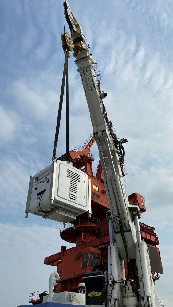
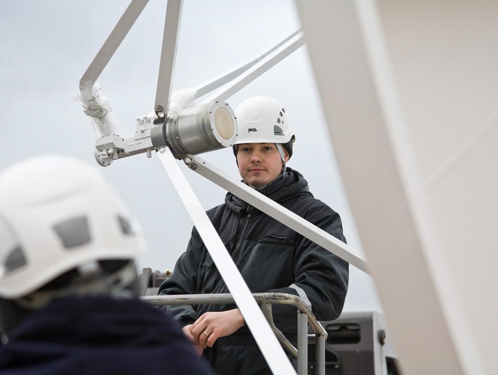
Original factory calibration performed on new instruments ISO 9001 f Calibration for regulated industries and reference instruments ISO/IEC 17025 f Configurable calibration for customer-specificneeds f f f f f Much more than a calibration f Calibrwww.vaisala.com/calibrationationservices f f f 299



Personalize your agreement by choosingBenefit AgreementCare Fixed pricing Planned calibrations f Free shipping f Priority order handling Easy return process f NumCalibrationberof calibrations Duration of the agreement Payment options4213 How the Care return process works 1. f f 2. f 3. f 4. f Calibration Care agreement f f f 300




Frequently asked questions about calibration
•••
All electronics and sensors drift over time. It is important to verify accuracy and make adjustments if needed. A calibration certificate is often required by internal or external quality standards.
Calibration refers to comparing the output of a measurement instrument against a reference instrument and only reporting the result. Adjustment refers to changing the output to correspond the output of a reference instrument. often should I calibrate?
• 301
Why is calibration important?
The most common calibration interval is 12 months but the interval depends on your accuracy requirements, operating environment, and your system's quality requirements.
•• How
Calibration versus adjustment?
Extended warranty f f f f f f f Maintenance and repair f f f Training services ff f Spare parts f f ff f 302
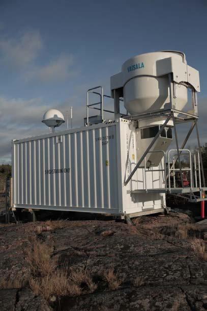


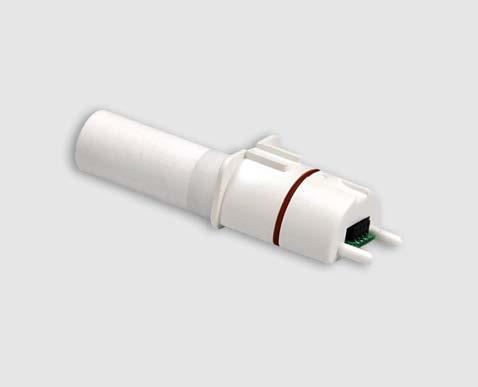
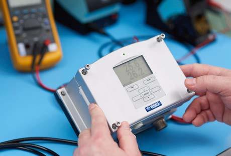
Technical support f f Remote services f ff f Modernization fff f f f 303
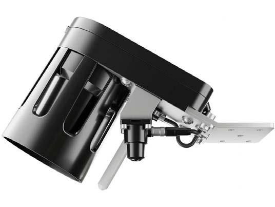




At your service worldwide • Global technical support • Network Operation Center • Service Centers • Field service How to order our services? Contact your local Sales or reach out via MyVaisala f www.vaisala.com/support View and order 24/7 via Vaisala Online Store for services such as Calibration f store.vaisala.com www.vaisala.com 304




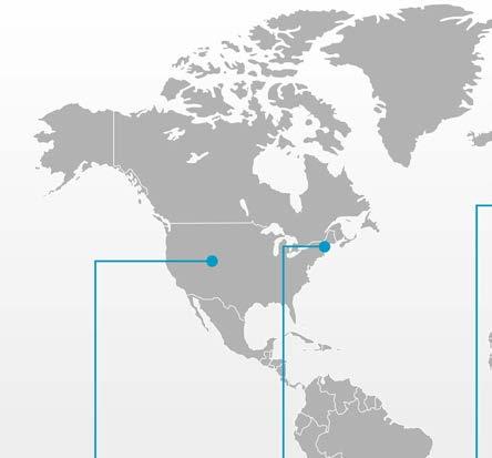
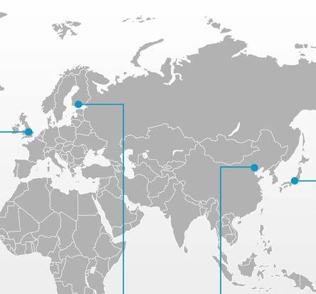


Features
The NOC team is fully trained on the full road solution and has direct access to Vaisala’s global technical expert network for escalations when needed.
In most cases, Vaisala is responsible for the sensor measurement technology at the roadside as well as for the data flow to the hosted system, plus winter maintenance decision-making tools such as Vaisala RoadDSS and Vaisala Wx Horizon. This allows Vaisala to investigate complete data flow chains.
Depending on your needs and system architecture or regional location, Vaisala can offer remote network monitoring and diagnostics, escalations to predefined contacts, or even roadside repair services. Please contact Vaisala sales or a partner representative for more information to create a service that meets your organization’s needs.
issues may arise, for example, around mobile network status, station or sensor operation, or power supply failures. When problems occur, Vaisala can help provide timely and appropriate actions to return the stations back to the required operating state.
Customized service
305
Building up and hosting a monitoring center can be time-consuming, complicated, and expensive. Instead, Vaisala 24/7 Sensor Monitoring and Diagnostics can provide a full solution for RWS lifecycle support in an ongoing, proactive, and e cient manner. The trained technical staff in the NOC consider potential issues, analyze each case, and implement corrective actions or provide guidance to resolve the issue.
•Vaisala NOC has end-to-end knowledge backed up by the Vaisala global technical expert network Ensure mission-critical data
f
Vaisala has in depth knowledge of the whole system, and monitoring is not limited to basic station data availability.
•Ensure reliable and continuous mission-critical data •24/7 remote monitoring and diagnostics of Vaisala full-stack solutions: no need to dedicate other resources to monitoring
The NOC team can analyze individual data values, inspect sensor performance history, and remotely restart stations.
Vaisala end to end knowledge It can be challenging to have a welltrained team on road weather stations.
The primary requirement of a road weather station is reliable and continuous data, flowing as scheduled for road maintenance teams. Road maintenance decision makers must be able to access and trust the information every time that they make a critical Sometimesdecision.
Vaisala roads solution support
The Vaisala Network Operation Centre (NOC) provides remote monitoring and diagnostics service for Vaisala Road Weather Stations to make sure that the highquality data is continuously available. The service includes 24/7 monitoring backed up by trained technical experts. Any issues are identified and investigated, and appropriate corrective actions are taken as agreed.
Getting corrective actions right from the start helps to get the system back to normal state as quickly as possible.





Systems that can be continuously monitored with diagnosis:
Monitoring the quality and availability of road weather stations and sensor data, including the availability of camera images.
2)Weekly reports, which provide detailed data break outage records, can be made available for specific customers (this is not a default feature).
3)Third-party sensor integration and monitoring require separate discussion and customized agreement.
•Vaisala road weather stations: RWS200, RWCC, LX RPU and ROSA
•Data from road weather stations are sent to the Vaisala hosted service, where measurements are entered into internal roads monitoring software.
1)The following are not included in this service: SIM communication, cloud storage or digital application services, spare and wear parts, onsite execution or step-bystep executional support. These services can be provided as service extensions. Please contact sales for query and availability of service globally.
•If NOC is unable to resolve the issue, they create a ticket in the Salesforce system to inform you of the relevant details and escalate accordingly. Depending on the type of issue, this escalation could go to second-tier technical support, field services, engineering, or specified customer contacts.
•The NOC team investigates the fault, diagnoses the issue, and attempts to resolve the issue remotely. NOC can also manually suppress incorrect data to make sure that end users are viewing accurate data in the Vaisala or third-party decision-making application.
•Third-party weather stations 3) Daily Corrective Action Report: Summary of current and recent faults of weather station and sensor data, and who is investigating them.
•If the readings from the road weather station or the associated sensors go outside of a threshold for a certain amount of time, the system automatically detects the reading as a suspected fault and suppresses it from being displayed to end users.
Escalation to end-to-end Vaisala experts in second-tier technical support, field service, and engineering teams, or your specified contacts.
CUSTOMER MY VAISALA&COLLECTIONDATAPROCESSING R&D ENGINEERING& DATA SUPPORTSOFTWARE& CENTEROPERATIONNETWORK TECHNICAL SUPPORT & FIELD SERVICE ROADSTATIONWEATHERSITE 306
•Vaisala road and weather sensors: DSC211, DST111, WXT530 Series
•In case of any questions or concerns, end users may contact NOC via email, phone, or the MyVaisala portal 24/7.
Frontline diagnosis, initial troubleshooting, and remote restarts if required. Monthly Network Performance review: Summary of the network performance of your data. Customer notification of faults and updates as the case progresses to resolution.
Remote monitoring and diagnostics Service description 24/7 sensor monitoring 1) Periodic reporting 2) Escalation for resolution
Service escalation procedure
•All information and communication regarding the issue is recorded in the Salesforce ticket to make sure that you have a single point of contact, and that the Vaisala expert has all the details related to the case to help resolve it.
System description and requirements for customer system
[Optional] Customer-provided secure connectivity
Either white-listed bi directional access from Vaisala IP addresses or a dedicated VPN to tunnel through to customer network, for data collection and remote configuration or troubleshooting. Observation data can be received through system polling or RWS pushing. White-listing incoming IP addresses provides secure access for the customer and/or local integrator/service provider to log in to the system. A secure VPN is recommended for this solution. www.vaisala.com
[Preferred] Vaisala-supplied secure cellular connectivity
Secure bi directional mobile network cellular service using Vaisala suppliers. The system supports a private static IP address or a secured public IP address for RWS data collection and remote access for configuration or Observationtroubleshooting.data can be received through system polling or RWS pushing. This solution is typically the easiest option as Vaisala is responsible for the whole communication chain. Availability of this service depends on customer location. Please contact Vaisala sales for more details.
307
Depending on your needs and system architecture or regional location, Vaisala can offer remote network monitoring and diagnostics, reactive remote diagnostics, escalations to pre-defined contacts, or on-site repair services. Please contact Vaisala sales or a partner representative for more information to create a service that meets your organization’s needs.
Building up and hosting a monitoring center can be time-consuming, complicated, and expensive. Instead, the NOC 24/7 monitoring and diagnostics can provide life-cycle support in an ongoing, proactive, and e cient manner.
•Vaisala NOC has end-to-end knowledge backed up by the Vaisala global technical expert network Ensure mission-critical data
The primary requirement for a weather radar is reliable and continuous data, flowing as scheduled for meteorological organizations and other authorities, such as airports, responsible of missioncritical operations. It gives operators the accurate weather information they need for early and correct operational Whendecisions.problems related to radar system operations occur, Vaisala can provide timely and appropriate actions to return radar operation back to the required operating state.
We do not collect observation data, so your data security is maintained.
The Vaisala Network Operation Centre (NOC) provides remote monitoring and diagnostics service for Vaisala weather radars to ensure the high-quality data is continuously available. The service includes 24/7 monitoring backed up by trained technical experts, so that any issues are identified and investigated, and appropriate corrective actions agreed.
f
Vaisala end to end knowledge It can be challenging to have a welltrained team on weather radar network Withmaintenance.Vaisala’s deep knowledge across the whole system, monitoring is not limited to the detection of possible issues when they occur. The NOC team is fully trained on the radar monitoring and has direct access to the Vaisala global technical expert network for escalations when needed. NOC also ensures timely communication with customers in case of detected issue.
Potential issues are considered by NOC trained technical staff, who analyze each case and can implement corrective actions or provide guidance to resolve the issue.
Vaisala solution support
Weather radar experts can further analyze, troubleshoot, and possibly make some corrective actions through remote connection. If on-site intervention is needed, this service supports the preparation of correct spares and instructions for field teams. It can significantly speed up the process of getting the system back to normal.
Features
Customized service
In most cases, Vaisala collaborates with customers in the delivery and life-cycle service support phases of radar systems. This remote monitoring solution allows Vaisala to provide prompt diagnostic support and solutions for possible issues in system performance, often reducing the need for on-site intervention, and thus can significantly increase the uptime of the system.
308
•Ensure reliable and continuous mission-critical data •24/7 remote monitoring and diagnostics of Vaisala full-stack solutions: no need to dedicate other resources to monitoring
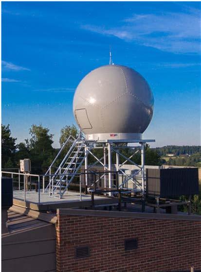
Escalation to Vaisala product experts in second-tier technical support, field service and engineering teams, or your specified Technicalcontacts. experts can remotely access the system and perform deep diagnosis and corrective actions.
1)The following are not included in this service: “SIM communication”, cloud storage or digital application services, spare and consumable parts, on-site execution or step-by-step executional support. These services can be provided as service extensions; please contact sales for query and availability of service globally.
2)Site infrastructure monitoring requires separate hardware solutions, such as dataloggers and temperature and humidity sensors, and requires a separate discussion and customized agreement.
•Initial troubleshooting and frontline diagnosis when required.
•Status and event data from the system are sent to the NOC through a secure VPN tunnel, where measurements are fed into Vaisala monitoring system.
•The NOC team investigates the fault, diagnoses the issue, and attempts to resolve the issue remotely.
•All information and communication regarding the issue is recorded in the ticket to make sure that you have a single point of contact, and that the Vaisala expert has all the details related to the case to help resolve it.
Service escalation procedure
CUSTOMER MY VAISALA&COLLECTIONDATAPROCESSING R&D ENGINEERING& DATA SUPPORTSOFTWARE& CENTEROPERATIONNETWORK TECHNICAL SUPPORT & FIELD SERVICE WEATHERSITERADAR 309
•Site infrastructure monitoring (e.g. radar cabinet, shelter, radome humidity and temperature) 2)
•Customer notification on faults and updates
•In case of any questions or concerns, end users may contact NOC via MyVaisala portal 24/7.
•Vaisala weather radars
Continuous monitoring of the system critical alarms and events status and automated alarming of the following systems:
Service description 24/7 monitoring 1) Periodic reporting Escalation for resolution
•Case creation, status updates, and resolution summaries
•If the status and events from the system or the associated sensors go outside of a threshold for a certain amount of time, the system automatically detects the reading as a suspected fault, and displays an alarm to the NOC team.
•If NOC is unable to resolve the issue, they create a ticket to inform you of the relevant details and to escalate the issue accordingly. Depending on the type of issue, this escalation could go to second-tier technical support, field services, engineering, or customer-specified contacts.
[Optional]
Customer-provided secure connectivity
A dedicated VPN tunnel through to customer network, for status and event information and remote configuration or troubleshooting. A secure VPN is recommended for this solution.
www.vaisala.com
This service is available for the compatible IRIS versions. Radars with older versions will need an update first.
System description and requirements for customer system
[Preferred]
Being an always-on service in the endpoints, the firewall and tra c encryption policy is enforced for all relevant network tra c, all the time. Nothing sensitive escapes, and nothing unintended enters the customer’s remotely monitored observation systems, and only Vaisala authorized personnel can access the Thissystems.solution is typically the easiest option, as Vaisala can perform the installation, and the customer only needs to open specific ports in the intermediate firewall to allow secure tra c from the customer system to NOC. Please contact Vaisala sales for more details.
310
All the network tra c to/from the customer observation system and Vaisala remote services is protected with a network security VPN product supporting state-of-the art security features. The network tra c protection is based on client – server architecture where the client side is installed in the customer’s remotely monitored observation system and the server side is installed in the NOC. The mutual authentication between the client and the server is based on public key certificates (X.509), and state-of-the-art cryptographic settings and protocols are applied for the encryption of the network tra c.
Vaisala-supplied secure VPN connectivity
Vaisala www.vaisala.com/deweathersales.GERMANYD-22607NotkestraßeGmbH11Hamburggermany@vaisala.com
UNITED KINGDOM Vaisala BirminghamLtd O ce 6230 Bishops Court Birmingham Business Park Birmingham B37 7YB UNITED wuksales@vaisala.comKINGDOMww.vaisala.com
Vaisala Inc. Boston O ce 10-D Gill Street Woburn, Massachusetts 01801 www.vaisala.comNorthAmericaInsideSales@vaisala.comWEA-USA
Vaisala contact information FRANCE GERMANY
Vaisala Serviços de Marketing Ltda Ladeira da Gloria 26 Bloco 3 – Studio 206 Glória, Rio de Janeiro RJ www.vaisala.com/ptweatherBRAZIL22211-120sales.latinamerica@vaisala.com 311
AMERICAS U.S.A. MEXICO BRAZIL Vaisala BoulderInc.O ce 194 South Taylor Avenue Louisville, Colorado 80027 www.vaisala.comNorthAmericaInsideSales@vaisala.comWEA-USA
EUROPE FINLAND
Vaisala SAS Paris O ce Tech Park 6A, Rue René Razel F-91400 Saclay www.vaisala.com/frweathersales.europe@vaisala.comFRANCE
Vaisala Oyj P.O. Box www.vaisala.comweatherFINLANDHelsinkiFI-0042126sales.europe@vaisala.com
Vaisala México Limited México O ce Sócrates 140 Col. Polanco Sección II Del. Miguel Hidalgo CP 11540, CDMX www.vaisala.com/esweathersales.latinamerica@vaisala.comMÉXICO
Vaisala China Ltd Beijing O ce Floor 2, EAS Building No. 21, Xiao Yun Road, Dongsanhuan Beilu Chaoyang District 100027 Beijing P.R. www.vaisala.com/zhCHINA
ASIA PACIFIC AUSTRALIA CHINA MALAYSIA
AND
Vaisala Sdn Bhd Regional O ce Malaysia W11-A0, Level 11, West Block Wisma Golden Eagle Realty 142-C Jalan Ampang 50450 Kuala Lumpur www.vaisala.comweathersales.malaysia@vaisala.comMALAYSIA
Vaisala Pty Ltd Melbourne O ce 3 Guest Hawthorn,StreetVIC 3122 www.vaisala.comsales.melbourne@vAUSTRALIAaisala.com
JAPAN Vaisala KK Tokyo O ce Jimbocho Mitsui Building 16F 1-105 Kanda-Jimbocho www.vaisala.com/jaweathersales.japan@vaisala.comJAPANTokyoChiyoda-ku101-0051 www.vaisala.com 312
313
This material is subject to copyright protection, with all copyrights retained by Vaisala and its individual partners. All rights reserved. Any logos and/or product names are trademarks of Vaisala or its individual partners. The reproduction, transfer, distribution or storage of information contained in this brochure in any form without the prior written consent of Vaisala is strictly prohibited. All specifications — technical included — are subject to change without notice. Please contact us at www.vaisala.com/requestinfo
314
B212441EN-B © Vaisala — April 2022