
International Research Journal of Engineering and Technology (IRJET) e-ISSN: 2395-0056
Volume: 13 Issue: 03 | Mar 2026 www.irjet.net p-ISSN: 2395-0072

International Research Journal of Engineering and Technology (IRJET) e-ISSN: 2395-0056
Volume: 13 Issue: 03 | Mar 2026 www.irjet.net p-ISSN: 2395-0072
Vaishnavi Chousalkar 1 , Dr SV Chaitanya2 , Mr. Manish Mahajan3
1 Student, Dept of Mechanical Engineering
2Associate Professor, Dept of Mechanical Engineering, AISSMS COE
3CEO at ICON Precision Engineering
Abstract - Quality assurance (QA) in manufacturing is essential to prevent defects, ensure product consistency, and comply with safety standards, ultimately reducing costs and enhancingbrandreputation.Byimplementingproactive,stepby-step procedures throughout the production cycle, manufacturers avoid costly rework, minimize waste, and maintain high levels of customer satisfaction. This paper contains insights of Quality Assurance, Control and manufacturingprocessesgainedduringmyinternshipperiod at ICON Precision Engineering Company. The paper covers elements of Quality Assurance and Manufacturing processes like Turning on CNC, Drilling, Milling on VMC, Spline Rolling and Cylindrical Grinding Processes.
Key Words: Quality Control, Quality Assurance, MSA, Statistical Process Control Parameters, Quality Control Tools, Inspection tools, CNC Turning, Grooving, Facing, Centering, VMC Milling, Drilling, Tapping, Boring and VMC Tools.
Qualityinmanufacturingmeansconsistentlycheckingparts that meet or exceed customer expectations and specifications,achievedthroughcontrollingprocessesfrom inwardofmaterialtodispatch,minimizingdefects,reducing waste, and ensuring reliability, performance, and safety through QualityAssurance(QA) andQuality Control (QC). It’s about achieving a predictable, controlled process that delivers “right first time” products, building brand reputation, and gaining a competitive edge. Production processesformthebackboneofmanufacturingandservice industries, transforming raw materials, information, and resources into finished goods and value-added services. Manufacturingprocessestakingplaceonworkpieceadhere to the Process Flow Diagram prepared by the respective companyfrominwardofrawmaterialtothefinaldispatchof finishedproduct.Forinstance,Inwardofrawmaterialwith specified diameter. Production department gives raw materialissuesliptostoreforissuingrequiredquantityof raw material from the store. In incoming inspection raw material diameter is checked and workpiece visually checkedtoseeforanydents.Ultrasonictestcarriedoutto check for cracks or pores and chemical testing of raw material takes place for chemical composition. Once the resultsofallthesetestscomecorrect,rawmaterialgoesto
storeforproduction.OnAutomaticCuttingMachinematerial iscuttolengthasgivenoncontrolplandrawing.Incutting, diameterisnotchanged.Onlylengthofrodisreduced.For saferside,lengthofrodkeptoncontrolplanis1.5to2mm greater than that on the customer drawing to account for extra material removal. On the subsequent CNCs Facing, Centering, Turning, grooving operations take place after which spline Rolling or Thread rolling takes place. Cylindrical Grinding Process carried out on some Shafts. Some jobs are black odised before dispatch. After all the processesjobsundergofinalinspectionafterwhichtheyare dispatched.
SpecialcharacteristicsorCriticalparameterswhenever a Shaft is produced by a given customer drawing include:-
Threads: Threads are checked as critical dimensions because they are fundamental to the assembly, structural integrity, and functionality of mechanical components.Minordeviationsinthreadpitch,diameter, or angle can lead to, or result in failed assemblies. Incompatible threads (mismatched sizes) will not fit togetherorwillnottightenproperly.
Spline:EnsuringPreciseFitandAssembly.Splinesmust fittogetherwithspecifictolerancestoallowforsmooth assemblyanddisassembly.
Grinding: Grinding is used to achieve extremely tight tolerances and superior surface finishes that earlier processes like turning or milling cannot achieve. Part Functionality & Assembly: Grind surfaces must fit perfectlywithinanassembly,andvariationscanaffect thefunctioningofbearings,hydraulicsystems,orengine components.
Hobbing:ToEnsureTheyFitandFunctionGearsmust meshperfectly.Iftheteetharetoothick,toothin,orthe wrongshape,thegearswillnotwork,ortheywillbreak.
International Research Journal of Engineering and Technology (IRJET) e-ISSN: 2395-0056
Volume: 13 Issue: 03 | Mar 2026 www.irjet.net p-ISSN: 2395-0072
Measurement System Analysis evaluates how good measurement system (Measuring instruments; Vernier Caliper, Gauges, Micrometer, Operator skill, part being measured,measurementmethod)is.Ensuresthatvariability inmeasurementfallswithinacceptabletolerances.
Elements of MSA: -
1) Accuracy:Howclosemeasurementistotruevalue.
2) Bias:Measuredandtruevaluedifference.
3) Linearity: Checks if bias remains same across all measurementrange.
4) Stability:Measurementsystemgivessameresultswith time. Same part, same instrument, same operator, differenttime.
5) Accuracy:Howcloserepeatedmeasurementsaretoeach other.
6) Repeatability:Variationwhensameoperatormeasures samepartwithsameinstrumentmultipletimestoget multiplereadings
GaugeRepeatability:Sameoperatormeasuressamejob withsamegaugemultipletimes.
7) Reproducibility: Variation due to different operator. Samepartmeasuredbydifferentoperators.
GaugeReproducibility-Differentormultipleoperators measuringsamejob.
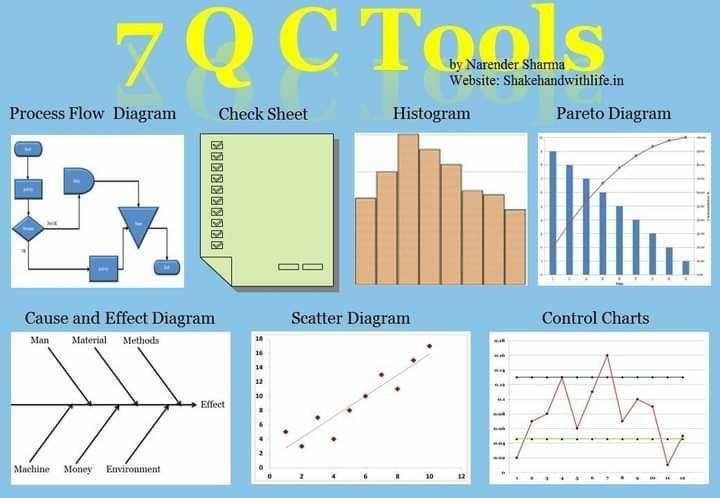
1) CheckSheet:ChecksifAllprocessparametersarefilled correctly.
2) FishBoneDiagram:ChecksforRootcauseofDefects
3) Control Chart: Controls stability of process. Plotted pointsshouldlieb/wUCL(UpperControlLimit)andLCL (LowerControlLimit).
4) Histogram: -
XAxis:DiameterRange
YAxis:No.OfShafts
5) ParetoChart:Bargraphthatidentifiesdefectcauses.
6) Scatter Diagram: Usedinqualitycontroltoanalyzethe relationshipbetweentwovariables,typicallyapotential cause(independentvariable)onthex-axisandadefect oreffect(dependentvariable)onthey-axis.
7) Process Flow Diagram: Sequence of processes from inward of raw material to dispatch of products. RepresentedwithBoxesandArrows.
Statistical Process Control: -
Catchesproblemsinprocessduringproductionbefore wrongpartsareproduced.
Ifthereadingsofdiameterofuppershaftwhenplotted oncontrol chartfallsabove UCL andbelow LCL,the processneedstobecorrectedtopreventiffromfalling belowLTLandaboveUTLandbecomingunstable.
Ifthereadingsofdiameterofuppershaftwhenplotted on control chart lie between UCL and LCL, then the ongoingprocessisstable.Partslieb/wUTLandLTL.
Cp:Process PotentialMeasuresiftheprocessspread fits within the engineering tolerance (Upper SpecificationLimit–LowerSpecLimit).Cp>=1.33For processtobestable
Cpk : Process Capability IndexMeasures actual capability of process by considering proximity of Processmeantonearestspecificationlimit.Cpk>1.67 forprocesstobestable.
E] Inspection Tools:
1) AttributeGauges:Gonogoprinciple,pass,orfail.
PrincipleofAttributeGauges:-
Jobshouldgothrough‘go’partofgauge. So,jobaccepted.
Jobshouldnotgothrough‘Nogo’partofgauge. Ifitgoesthrough‘Nogo’partofgauge, Jobisrejected.
International Research Journal of Engineering and Technology (IRJET) e-ISSN: 2395-0056
Volume: 13 Issue: 03 | Mar 2026 www.irjet.net p-ISSN: 2395-0072
TypesOfAttributeGauges:-
1) PlainPlugGauge:TocheckInternalDiameter.
2) ThreadPlugGauge:TocheckInternalthreads.
3) Thread Ring Gauge: To check Outer diameter threads.
4) PlainRingGauge:TocheckOuterDiameter.
5) WidthGauge:Tocheckslot.
6) SnapGauge:TocheckOuterdiameter.
7) SplineGauge:TocheckforSpline.
2) Variable Gauges: To measure dimensions of parts produced and verify if they are in acceptable tolerancesaccordingtocustomerdrawing. TypesofVariableGauges:
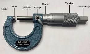
1. Micrometer: To measure Outer Diameter. Leastcount:1Micron
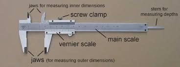
2.VernierCalipher:TomeasureOD/ID,Depth,Groove
Diameter,length
LeastCount:10Micron
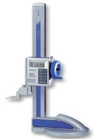
3.DigitalHeightGauge:
Tomeasureverticaldistancesorlength.
Leastcount:10Micron
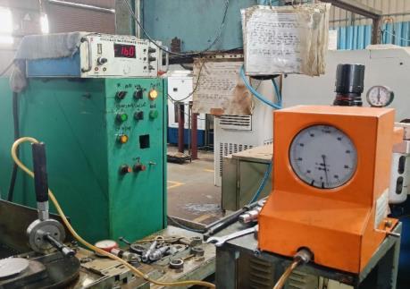
4.AirPlugGauge:UsedtocheckthejobafterGrinding operation.Why? 1)Forlowtolerances2)Forlowcycletime
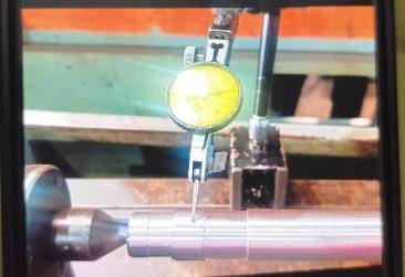
5. Bench Centre: Inspection tool used to check circular runoutoftheShaftaspergivencustomerdrawing.
1.Inward Inspection: Checks diameter of raw material, chemicaltestingofrawmaterialforchemicalcomposition, ultrasonictesttodetectcracksorporesinsiderawmaterial.
2.InprocessInspection:Checksthedimensionsofpartsas theyareproducedwithmicrometer,vernier,heightgauge, taper checking by placing ball, checking pin diameter to checkforspacingb/wteethcreatedbyhobbingtomakesure thattheyfallwithinacceptabletolerances.Datamaintained inSetupApprovalReport
International Research Journal of Engineering and Technology (IRJET) e-ISSN: 2395-0056
Volume: 13 Issue: 03 | Mar 2026 www.irjet.net p-ISSN: 2395-0072
3. Final Inspection: Checks the parts before they are dispatchedthroughgoand no-gogauges.Visuallychecked foranydents,burrsetc.
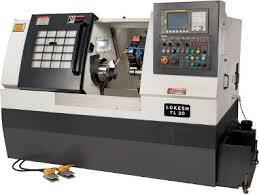
OperationsperformedonCNCinclude:
a) Facing: The process of machining the end of a workpiecetocreateaflatsurfaceperpendiculartothe axisofrotation.
b) Centering: Drilling a small conical hole (center hole) intotheendfacetoestablishaprecisecenterpointfor holdingtheworkpiecebetweencenters(revolvingand deadcenters)onsubsequentCNCs.
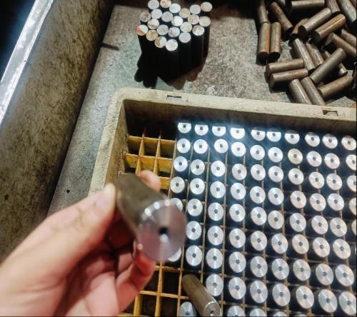
c) Turning: Reducing diameter of workpiece. The workpieceisclampedinachuck(deadandrevolving centers)andspunathighspeedswhileasingle-point cuttingtoolmoveslinearly(axesXandZ)toshapeit. CNC turning is a precise, subtractive machining process where a workpiece rotates on a CNC lathe while a stationary cutting tool removes material to createcylindricalpartswithhighaccuracy.
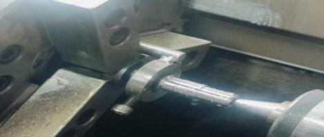
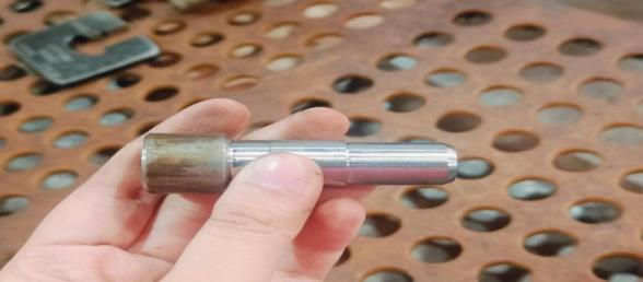
d) Straight Turning: Straight Turning in CNC is a fundamentalmachiningprocesswhereacuttingtool movesparalleltotheaxisofarotatingworkpieceto reduce its outer diameter uniformly. It is used for producingprecisecylindricalcomponentslikeshafts andpins,oftenrequiringbothroughingandfinishing passes to achieve required dimensions and surface finishes.
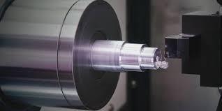
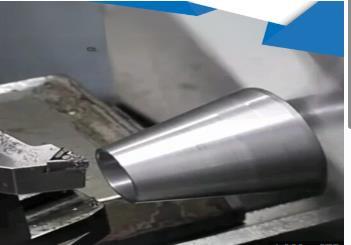
e) TaperTurning:TaperturninginCNCisamachining process that produces a conical, uniformly angled surfacebygraduallychangingaworkpiece'sdiameter along its length. Morse tapers, tools, and tapered shafts.
f) Grooving: Grooving in CNC machining is a turning operation that cuts narrow, precise, and often deep, rectangular, or specialized cavities (grooves) into a workpiece'sexternal,internal,orfacesurfacesusinga CNClathe.
International Research Journal of Engineering and Technology (IRJET) e-ISSN: 2395-0056
Volume: 13 Issue: 03 | Mar 2026 www.irjet.net p-ISSN: 2395-0072
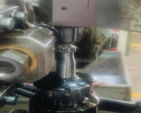
Gear hobbing is process of generating gear or generating teeth on shaft or workpiece by means of cuttercalledhob.Teethcuttingonshaftinvolvesthree basic motions. Hob and blank or shaft has rotating motion and third one is radial advancement of hob. Blank is first moved in towards rotating hob until properdepthisachieved.Hobcutterfedacrosstheface of shaft until teeth are complete. Both hob and gear rotate during process. The hob moves longitudinally alongthelengthoftheshaft.
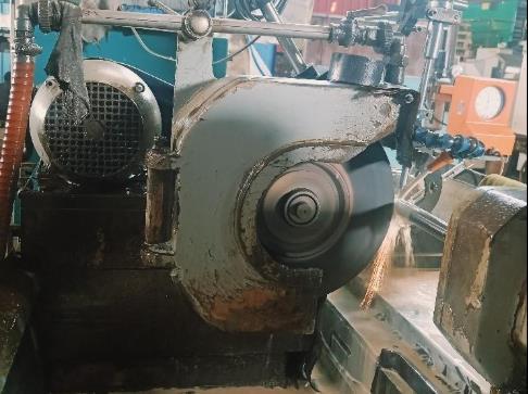
Cylindrical grinding is a high-precision machining processthatusesarotatingabrasivewheeltoremove material from a rotating cylindrical workpiece, achievingsuperiorsurfacefinishandstrictdimensional tolerances.Itisprimarilyusedtogrindexternal(OD)or internal(ID)diameters,tapers,orcamsonshafts,pins, andbearings.InatypicalCylindricalGrindingMachine, the workpiece undergoes rotation along its axis, supported by two centers. The high-speed rotation of thegrindingwheelservestogrindbothcentersonthe workpiece'saxis,resultinginthecreationofapolished andevensurface.ODgrindingisgrindingoccurringon externalsurfaceofanobjectbetweenthecenters.The centersareendunitswithapointthatallowtheobject toberotated.Thegrindingwheelisalsobeingrotatedin the same direction when it comes in contact with the object.Thiseffectivelymeansthetwosurfaceswillbe movingoppositedirectionswhencontactismadewhich allowsforasmootheroperationandlesschanceofajam up.
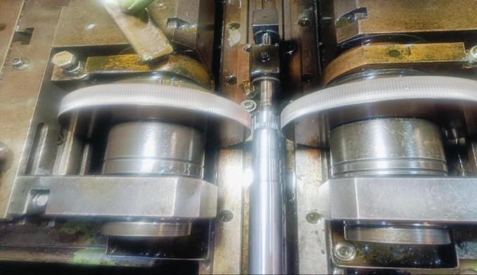
3.
Thread rolling/Spline rolling is done by using pair of circular rolls with the identical threads or splines to transfer work material through plastic deformation ratherthancuttingormaterialremoval.Workpieceor shaft placed between fixed and movable circular rolls thathasgroovescorrespondingtotargetthreads.Under pressureworkpiecerolledbetweentworolls,resulting in thread pattern/spline pattern being pressed into workpiece without production of chips. It is metal forging technique. Types of die used are flat rolls and circular rolls. Rolls used in these images are circular rolls.
4. Blackodising
Blackodising is a process that forms a corrosionresistantcoatingonferrousmetalsthroughachemical reactionwhenimmersedinahotalkalinesaltsolution. Thisisdonetopreventrustformation.
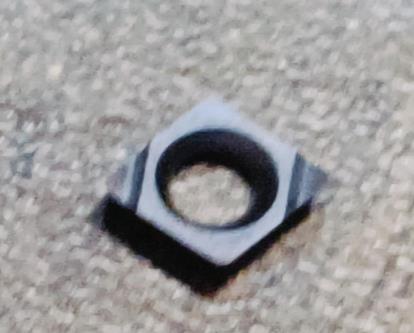
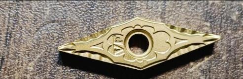
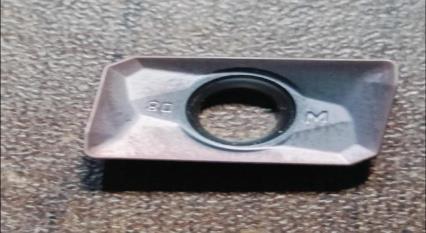
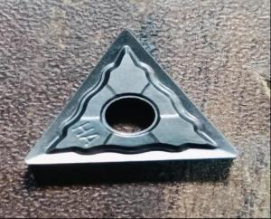
CNCinsertsaresmall,replaceablecuttingtoolsusedinCNC machinestoremovematerialfromworkpieces.Theseinserts are designed to be easily interchangeable, allowing operatorstoquicklyreplacewornordamagedcuttingedges withoutchangingtheentiretoolholder
International Research Journal of Engineering and Technology (IRJET) e-ISSN: 2395-0056
Volume: 13 Issue: 03 | Mar 2026 www.irjet.net p-ISSN: 2395-0072
A VMC machine is short for Vertical Machining Center. Wherethespindle,whichistheaxisthatholdsthecutting tool,isorientedvertically(i.e.upanddown).Theworkpiece sitsonatablebelow,andthecuttingtoolcomesdownonit. Bench wise or fixture holds the workpiece on VMC table whichmovesinX,Yaxis.Cuttingtoolmovesupanddown along z axis. There are three axes in VMC. Workpiece remains stationary. Movement of cutting tool takes place. VMCs use multiple tools for different operations. The Automatic Tool Changer (ATC) swaps tools automatically, reducingdowntimeandimprovingproductivity.
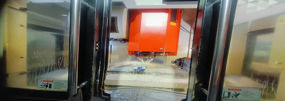
Operations performed on VMC include:
a) Milling:Millingistheprocessofmachiningusingrotary cutters to remove material by advancing a workpiece intothecutter.Thismaybedonebyvaryingdirections. Milling is used to create slots, achieve smooth surface finishandforshapingthematerialasandhowrequired.
b) Drilling:Drillingisprocessofprocessofproducinground holesinaworkpiecewiththeuseofmultipointcutting toolcalleddrill.Drillisrotarycuttingtoolwithflutesfor passageofchipsandforadmissionofcoolant.
c) Boring:Machiningprocessthatenlargespredrilledhole forachievinghighaccuracy,finishandsmoothness.Tool usedisdrillbit.
d) Tapping: Tapping is a machining process that creates internalthreadsinapre-drilledhole,allowingboltsor screws to fasten components securely. Utilizing a tool calledatap madeofhigh-speedsteelorcarbide the processinvolvesrotatingthetoolintotheholetocutor formthreads.
1.Drills
a) U Drill: U drill uses inserts to drill hole of given depth (true coolant) in one cut. Rough drilling takes place. It is usedforhigh-speeddrillingwithlowcycletime.
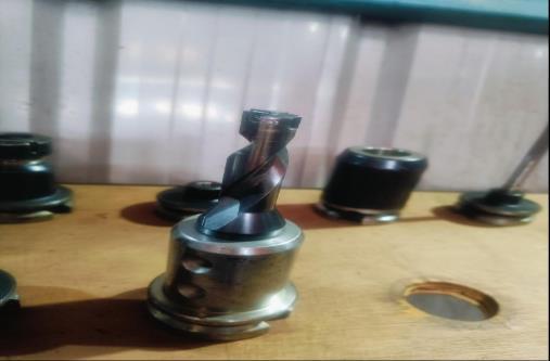
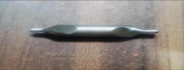
b) Centre Drills: Centre drill is used in a VMC (Vertical Machining Centre) primarily to create an accurate, rigid startingpointforsubsequentdrillingoperations.Becauseof
International Research
Volume: 13 Issue: 03 | Mar 2026 www.irjet.net p-ISSN: 2395-0072
its short, thick, and rigid construction, it prevents larger twistdrillsfrom“wandering”ordeflectingonthematerial surface, ensuring precise hole positioning and improved surface finish. The rigid, short tool creates a small conical hole that guides the tip of the follow-up drill, ensuring it startsexactlywhereintended,especiallyonunevenorhard surfaces.Significantlyimprovesthepositionaltoleranceof holes,whichiscrucialforCNCmachining.
c) Twisted Drill
TwistdrillsareusedinVerticalMachiningCenters(VMCs) primarily for their superior capability to create, enlarge, and produce high-quality cylindrical holes efficiently in a singleoperation.Thespiralflutes(grooves)allowchipsto exitthehole,preventingcloggingduringdeepdrilling.High Productivity: Designed for high-speed, automatic, and precise hole-making, they maximize metal removal in a minimalamountoftime.
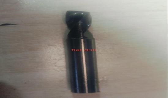
e) Flat drills:
Flat drills are used in Vertical Machining Centers (VMCs) primarilytocreateflatbottomedholesinasingleoperation, eliminating the need for secondary, time-consuming finishing passes. They are essential for precision applications, such as counterboring, drilling on angled surfaces,ortappingblindholes.
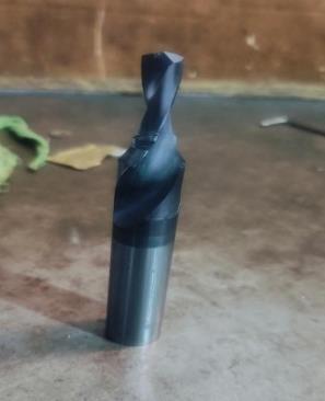
e)StepDrill:Stepdrillcandrillholesofvariousdiameters, save time, and reduce the need to carry multiple drill to individually drill holes of various diameters on the same workpiece.
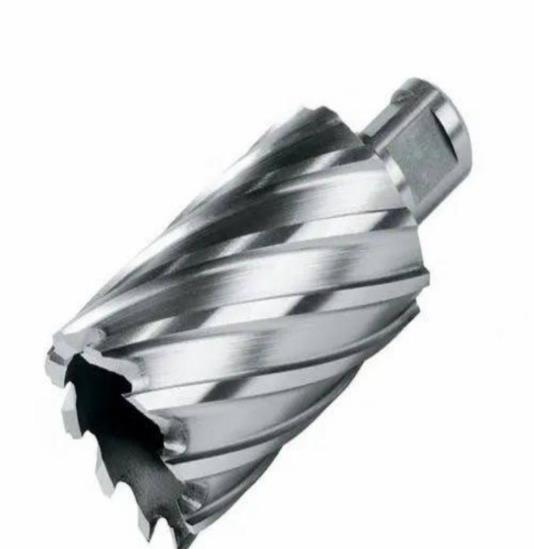
CoredrillsareusedinVerticalMachiningCenters(VMCs) primarilytocreatelarge-diameter,deep,orpreciseholes efficientlyinhardmaterials.Coredrillingremoves cylindrical,solidsamplesfromhardmaterialsunlikechip removalintwistdrill.Drillhasteethonit.
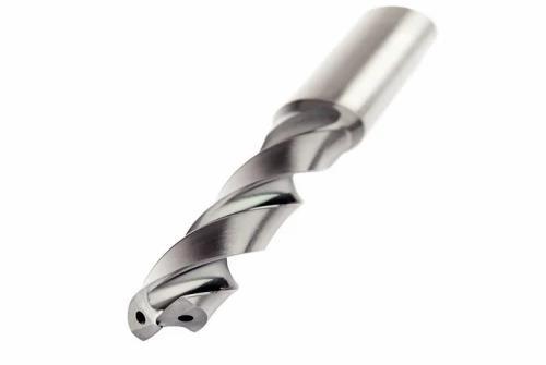
Through Coolant Drill:Through-coolantdrills(coolant-fed) areusedtosignificantlyincreaseproductivity,extendtoollife, andimproveholequalitybydeliveringcoolantdirectlytothe cuttingedge,evenindeepholes.Theyeliminatetheneedfor
International Research Journal of Engineering and Technology (IRJET) e-ISSN: 2395-0056
Volume: 13 Issue: 03 | Mar 2026 www.irjet.net p-ISSN: 2395-0072
frequent peck drilling, allow for higher cutting speeds, and prevent chip clogging. With this drill in one cut entire materialisremovedandinonegoaccuratediameterholeis drilled.
Reamer
Reamers:Reamerisusedafterdrillingtoachieveveryhigh andsmoothsurfacefinishfordrilledholes.Itisusedforlow tolerances.Forinstanceifaholeof14mmdiameteristobe drilled accurately,first drill will beused fordrilling hole of 13.75 mm which removes large amount of material. After drilling reamer will remove 0.25mm of material to get accurateholediameterof14mm.
5] Endmills in VMC
1)FlatSquareEndmill:Aflatsquareendmillhasaflatcutting endwithsharpcorners(90°edges).Cuttingstraightslotsor grooves in the workpiece. Example: keyways, channels, or rectangularpockets.Removingmaterialinsideacavitywith flatbottoms.Cuttingtheperimeteroroutlineofapartforside milling.
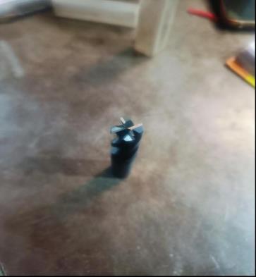
2)BallNoseEndmill:Aballnoseendmillhasaroundedtip insteadofaflatend.Thecuttingedgeissphericalatthetip, whichmakesitidealforcurvedsurfaces.Itisusedforprofile milling.Cuttingcomplex3Dshapes.Whenacavityorpocket hasaroundedbottom,aballnosecanproduceitdirectly.
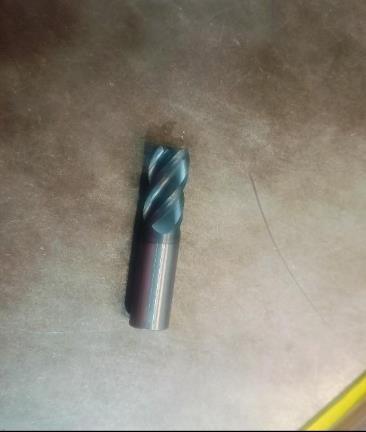
3)Tapered Endmill: To produce tapered holes. To create taperedslots.
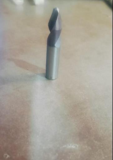
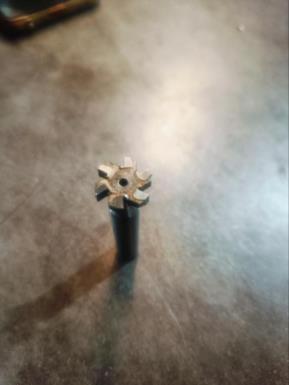
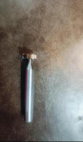
4)TSlotCutter:TslotcutterusedtocutTslotsinworkpiece.
International Research Journal of Engineering and Technology (IRJET) e-ISSN: 2395-0056
Volume: 13 Issue: 03 | Mar 2026 www.irjet.net p-ISSN: 2395-0072
6] Taps in VMC
1) Straight Taps: Straight flute taps (also known as hand taps)arethestandardtoolforcreatinginternalthreadsin pre-drilledholes.Becausetheirflutesrunstraightalongthe axis,theydonotautomaticallyejectchips,idealforthreading throughholes.
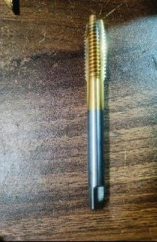
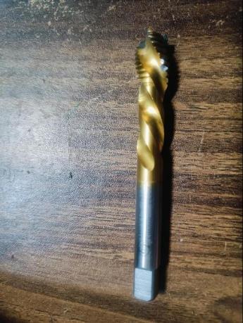
2)SpiralTap:Spiralflutedtapsdrawchipsoutofthehole, perfectforthreadingblindholes.
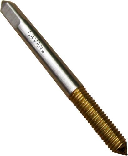
3) Form Tap: Form taps (or roll/fluteless taps) create internalthreadsby displacing material rather than cutting it, producing stronger,chip-free threads. They are used for threading holes in Aluminium material.
I would like to express my sincere gratitude to the Chief Executive Officer Mr Manish Mahajan of ICON Precision Engineeringwhosevisionaryleadershipandcommitmentto excellenceprovidedmewiththeopportunitytoundertake my internship in the field of Quality Control and Manufacturing Processes. The organization’s strong emphasis on innovation, continuous improvement, and operationalexcellencecreatedaninspiringenvironmentfor learningandprofessionalgrowth.Thehands-onexposureto real-world manufacturing practices and quality standards has significantly enhanced my technical skills and professionalconfidence.
I am thankful to my college internship mentor, Dr S V Chaitanya and all faculty members of Mechanical Departmentwhoseconstantguidance,encouragement,and valuable feedback helped me successfully complete this internship. Their academic support and technical insights enabledmetoconnecttheoreticalknowledgewithpractical applications in manufacturing systems, quality assurance techniques,andprocessoptimization.
[1] Operated as an Intern with primary focus on Quality AssuranceandManufacturingProcessesrelatedtoSteering Column Components at ICON Precision Engineering CompanylocatedatChikhali,Pune.
International Research Journal of Engineering and Technology (IRJET) e-ISSN: 2395-0056
Volume: 13 Issue: 03 | Mar 2026 www.irjet.net p-ISSN: 2395-0072
[2]StatisticalQualityControlandQualityManagementby authorR.C.Gupta
[3]MachiningandMachineTools-A.B.Chattopadhyay BIOGRAPHIES



VaishnaviChousalkar TEstudentatAISSMSCOE. Email: vaishnavichousalkar12@gmail. com
DrSVChaitanya AssociateProfessor,Deptof MechanicalEngineering, AISSMSCOE.Email: svchaitanya@aissmscoe.com
Mr.ManishMahajan CEOatICON PrecisionEngineering Email: manish.mahajan@iconprecisi on.in