
International Research Journal of Engineering and Technology (IRJET) e-ISSN: 2395-0056
Volume: 13 Issue: 01 | Jan 2026 www.irjet.net p-ISSN: 2395-0072
International Research Journal of Engineering and Technology (IRJET) e-ISSN: 2395-0056
Volume: 13 Issue: 01 | Jan 2026 www.irjet.net p-ISSN: 2395-0072
Ashutosh Eknath Satpute1 , Saikrishna Buddaram2, Ashish Deshpande3 , Harshal Bhamare4
1Assistant Design engineer, Tata Technologies Pvt. Ltd., Pune.
2Design Engineer, Tata Technologies Pvt. Ltd., Pune.
3Manager, Tata Technologies Pvt. Ltd., Pune.
4Design Engineer, Tata Technologies Pvt. Ltd., Pune.
Abstract - Clutch control/clutch actuation system plays animportantroleindisengaginggearboxfromenginewhile shifting gears in manual clutch transmission systems. In designing clutch actuation systems, it is necessary to consider vehicle type, route, and frequency of clutch actuation. Driver should not get a jerky feeling while engaging the clutch and it should not be a fatigue inducing job for the driver in case of frequent clutch operation. Therefore, it is necessary to maintain good pedal ergonomics and lower pedal effort for driving comfort. This in turn increasesclutch lifeand eliminates gearbox failures. A unique mathematical model has been developed to arrive at good pedal ergonomics for a particular percentile population and for a given seat location. Based on this model and benchmark study, we arrive at alternative designs that can meet the requirements with their advantages and disadvantages. Based on comparative analysis, design is finalized. This paper discusses the arrivinggoodergonomicpositionofpedalusingthismodel.
Key Words: Ergonomics, pedal, ergo, mathematical, driver, clutch, control, anthropometry
Ergonomics is broadly defined as, “How comfortable a system has been defined and / or created for a user to workwithit.”Insimplewords,itisthescienceofdesigning ‘thejobtofit’fortheworker,notforcingtheworkerto‘fit the job’. Ergonomics demands the human machine interaction to be smooth i.e. free from ergonomic injuries. Itisalsodescribedas‘HumanFactorEngineering’. Itplays a major role for its acceptance within the user base and makingtheproductsuccessful.
Accelerator, Brake and Clutch Pedal plays a vital role in automotive ergonomics, as driver remains in constant interactionwithpedalswhiledriving.Thus,pedalposition, orientationanditsassociatedefforthaveaprofoundeffect on driving comfort of the driver. The major constraint in designing the pedals with design intended position is vehicle packaging. Packaging of other aggregates, especially in commercial vehicles in same space leads to deviation from ideal position of pedals. This deviation causesthedeteriorationofpedalergonomicsofthevehicle, and quantifying the amount of debilitation is a problem. Simulation software’s have been designed to give the
reports based on the complete vehicular ergonomics, and doesnotallowdesignertofurthersubjugatecomfortfactor fortheimprovementsolelyinthepedalposition.So,ahigh discomfort value can also be caused by improper position ofsteeringwheelordifficultyinaccessibilityofgearshifter orimproperpedalpositionsorinsufficientseattravel.
SAEpaper(2017-26-0252)consistsofmathematicalmodel through which designer can run multiple iterations and finalizebestpossiblepedalpositionsbaseduponpackaging constraints.
Hip Breadth-The measured distance between the two humanhipcentres,markedwithabbreviationsH1andH2, infigure2
Thigh Length-The length corresponding to the human thigh,infigure3.
Lower Leg Length-The length corresponding to the lower legoftheleg,infigure3.
Foot Length-The length corresponding to human foot, in figure3.
Pedal Foot Length-The distance between heel point and BOF,infigure3.
Torso angle-The angle measured between the vertical line throughH-pointandthetorsoline,infigure3.
Thigh Angle-The angle measured between the thigh centreline and the horizontal line through H-point, in figure3.
Hip Angle-The angle measured between the torso centrelineandthethighcentreline,infigure3.
Knee Angle-The angle measured between thigh centreline andthelegcentreline,infigure3.
Ankle Angle-The angle measured between the lower leg centrelineandthefoot,infigure3.
ShoePlaneAngle-Theanglemeasuredbetweenthefloorof thevehicle(withcarpet)andthefootbase,infigure3.
International Research Journal of Engineering and Technology (IRJET) e-ISSN: 2395-0056
Volume: 13 Issue: 01 | Jan 2026 www.irjet.net p-ISSN: 2395-0072
LegSpreadAngle-Theanglemeasuredbetweenthethigh centrelineandtheverticallinefromHippoints,as representedinfigure2.
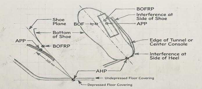
Fig.1: Depictionoftheergonomicterminologyatthefootof thedriverwhileoperatingthepedals.
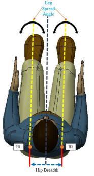
Fig.2:Depictionoftheergonomicterminologyintopview ofthedriverseated.
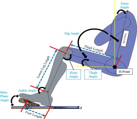
Fig.3: Depictionoftheergonomicterminologyinsideview ofthedriveroperatingthepedals.
Effective value of H30: The height of the H-Point fromthefloori.e.theH30valueasspecifiedinSAE J1100[1],valuetobeenteredaftersubtractingthe carpet thickness from it. For example, the H30 valueina vehicle is 430 mm,and the thickness of thecarpetis15mm,thentheeffectivevalueofthe H30willbe,430-15isequalto415mm.
For suspended type pedals, with pedal travel towardsfirewall,followingdetailsarerequired,
Pedalplateangle
Pedalleverangle
Pedal leverlength,tobecalculatedasindicatedin figure5below;
The human anthropometric data with respect to legsi.e.lowerleglength,thighlength,hipbreadth andfootlength.Forthedesiredtargetedpercentile population.
Clutchandacceleratorpedalplateangle.
Seat travel, the distance by which the seat can be pulledforwardfromitsrearmostrestingpoint.
Torso angle, minimum and maximum value of torsoangleistobesetinthemodelforthedriver comfort, keeping in view the driving visibility constraints.
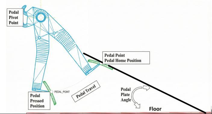
Fig. 4: Keyparametersforpedalergonomics.
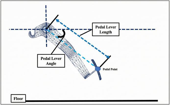
Fig. 5: Morekeyparametersforpedalergonomics
International Research Journal of Engineering and Technology (IRJET) e-ISSN: 2395-0056
Volume: 13 Issue: 01 | Jan 2026 www.irjet.net p-ISSN: 2395-0072
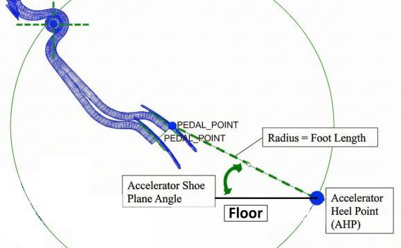
Below are leg comfort angles which are considered as limitsforgivingresults.
Manualmeasurementdoesn’tgivetheflexibilityof iterationsforoptimization.
Subjective jury analysis, the subjective analysis is basedonhintsthereby,cannotbestandardized.
LimitationofSimulationsoftwareisthatitdoesn’t steerstheuserstowardstheoptimizedvalues.
Table 1:Legcomfortangles.
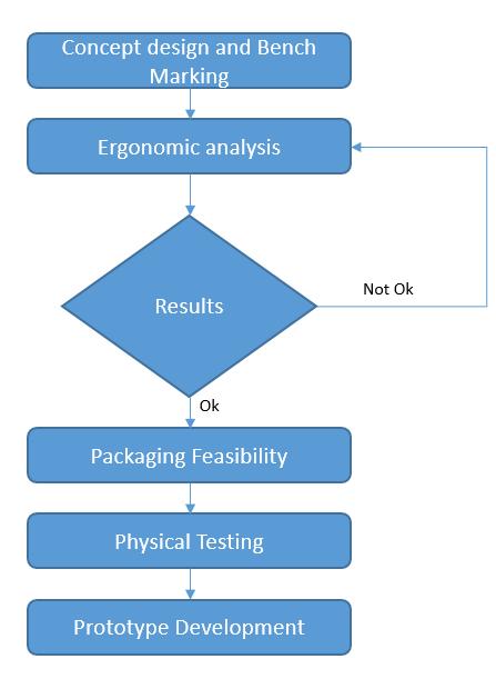
Refer below flow chart for working of model. Different iterationscanbedoneinmodeltoarriveatthefinal pedal positions. It reduces time of making CAD model and ergonomicanalysisinSimulationsoftware.
This model gives comfort angles for legs for various percentile population for accelerator, brake and clutch pedalaftermultipleiterations.
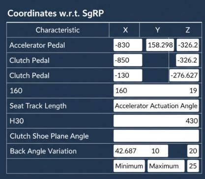
8: Depictionofsampleoutputusingthemodel. Acceptable results
Belowareasampleofacceptableresults
International Research Journal of Engineering and Technology (IRJET) e-ISSN: 2395-0056
Volume: 13 Issue: 01 | Jan 2026 www.irjet.net p-ISSN: 2395-0072
Characteristic
BackAngle Variation
Knowledge Based Engineering (KBE) approach
Knowledge engineering primarily deals with knowledge acquisition, representation, validation, inferencing, explanation, and maintenance. TheKnowledge EngineeringProcessgetscompletedinfivemajortasks:
7. 1. KNOWLEDGE ACQUISITION
Knowledge acquisition includes the process of acquiring knowledge, be it from human experts, books, documents, oranyotherrelevantsourceofnecessaryexpertise
7.2. KNOWLEDGE VALIDATION
In this step, the knowledge acquired from various sources isvalidatedandverified,usuallybywayoftestcases,until deemedacceptable.
7.3. KNOWLEDGE REPRESENTATION
After determining validation, knowledge gets organized into a knowledge representation. This task subsumes the preparation of a knowledge map and encoding the understandingintheknowledgebase.
7.4. INFERENCING
Once the knowledge representation gets established, businesses need to design the software to enable inferences based on that knowledge. Then, the system providesadvicetoanon-expertuser.
This task involves designing and programming an explanationcapabilitytoanswerspecificquestions,suchas whythereisaneedforaparticularpieceofinformationor howonecametoaspecificconclusion.
This model is more effective and accurate as compare to regularmodelandincreasestheproductivity
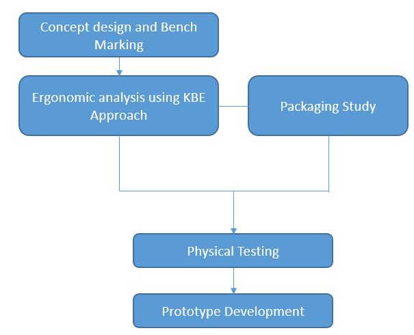
• It helps to increase the productivity of design engineer.
• Re-uses the captured knowledge so that any novicepersoncangeneratetheresults
• Reduces the design cycle time by faster computationofresults
NowadaysautomotiveOriginalEquipmentManufacturers are paying more attention on providing comfortable ergonomics positions of pedals but it is difficult meet the requirementofeachandevery(allpercentilepopulations) person because of packaging/ manufacturing/ costing constraint so here adjustable clutch pedal assembly provides the unique solutions to meet the drivers comfort requirementwithlowcostandlessdevelopmenttime.
International Research Journal of Engineering and Technology (IRJET) e-ISSN: 2395-0056
Volume: 13 Issue: 01 | Jan 2026 www.irjet.net p-ISSN: 2395-0072
References
[1] Survival Space for the Protection of the Occupants oftheCabofaCommercialVehicleAIS-029/2004
[2] SAE paper- 2017-26-0252- Analysis of Automotive Control Pedals Ergonomics through Mathematical Modelling Based on Human Anthropometry. Authors-Garg,S.,Bhide,S.,andGupta,S.
[3] SAE International Surface Vehicle Recommended Practice,“AccommodationToolReference Pointfor Class B Vehicles,” SAE Standard J1516, Rev. Oct. 2011.
[4] SAE International Surface Vehicle Recommended Practice, “Driver Selected Seat Position for Class B Vehicles - Seat Track Length and SgRP,” SAE StandardJ1517,Rev.Oct.2011.