International Research Journal of Engineering and Technology (IRJET) e ISSN: 2395 0056

Volume: 09 Issue: 07 | July 2022 www.irjet.net p ISSN: 2395 0072
International Research Journal of Engineering and Technology (IRJET) e ISSN: 2395 0056
Volume: 09 Issue: 07 | July 2022 www.irjet.net p ISSN: 2395 0072
1Research Scholar, BM College of Technology, Indore RGPV, Bhopal
2Professor and HEAD, BM College of Technology, Indore RGPV, Bhopal ***
Abstract Numerous geometrical and environmental parameters affect the durability and strength of the weld junction. Geometric characteristics that determine weld joint strength can be adjusted, but environmental conditions that influence weld joints are difficult to manage. The geometric optimization parameters are h,, and t. This optimization technique would produce the responses for equivalent stress, shear stress, and fatigue life along with the sensitivity of each optimization variable, h,, and t. ANSYS software is used to generate the CAD model of the weld joint and to carry out the FEA analysis. Since h has the highest sensitivity to shear stress and normal stress out of the three variables chosen for investigation, it should be given top consideration when designing weld joints.
Key Words: FEA,Weldjoint,ResponseSurfaceMethod
Thetwometalsareconnectedduringtheweldingprocess undertheproperthermophysicalconditions.Temperature, pressure,andmetallurgicalconditionsareexamplesofthese thermo physical circumstances. The range of working temperatures and pressures affects the welding process. Becauseweldingallowsfor directstresstransferbetween componentsandalsohelpstominimiseweight,iteliminates the need forany gussetsor plates.All industries, whether small or large, employ welding extensively. It is the main method for fabricating or mending metals, and it has applicationsinspaceaswell.
Figure1.3 Filletweldsindifferentjointsa)Lapjoint b) T joint c)Crossjoint[1]
The mechanical properties of weld joint are drastically affected by porosity, crack, internal concavity and lack of penetration. These defects cause fatigue failure which are critical.Theincompletepenetrationinducesstressandwhen subjectedtopressureitmaycausecrack
Thefilletandbuttweldarethemostcommontypesofweld usedasshowninfigure1.2andfigure1.3.Outofwhichthe perpendicular pieces are welded using fillet weld and parallelsurfacesareweldedusingbuttweld.
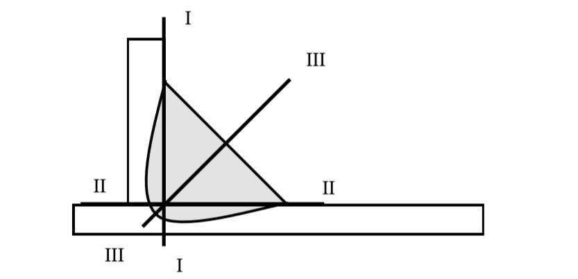
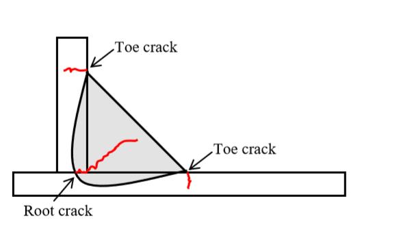
The weld dimensions have to be done by taking considerationofthreecriticalsectionsasshowninfigure1.4 below. These are section I, section II and section III. The crackinitiationtakesplaceinsectionIIIandwhilesectionII andsectionIcorrespondsweldtoecrackpropagation.There arethreepossiblemodesoffailureinweldjointwhichare toecrackatendsandrootcrackatbottommidasshownin figure1.5below.
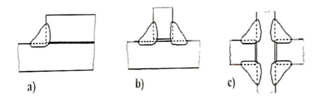
Figure1.4:Sectionsofinterestinaweld[1]
International Research Journal of Engineering and Technology (IRJET) e ISSN: 2395 0056
Volume: 09 Issue: 07 | July 2022 www.irjet.net p ISSN: 2395 0072
2.2Methodologyandmodelling
Figure1.5:Possiblefailuremodes[1]
Forsimplicityinsimulations,thefilletweldsareconsidered to be isosceles triangle as shown in figure 1.6 below. The nominalthroatthicknessistheheightoflargesttrianglethat canbefittedbetweenthejointfacesandtheweldsurface. The weld penetration determines throat thickness. The throat thickness ��0 is the dimension used in various manufacturingdrawings
1.3 Detailed objectives: 1>UsingANSYSdesignmodeller,CADmodellingofthetube flangeweldedjointillustratedinthepreviousfigure 2> FEA structural analysis using ANSYS software and torsionalloadingconditions 3. Calculating shear stress, deformation, fatigue life, and additionalstresses. 4>Choosingtheoptimizationvariableshand 5>UsingTaguchidesignofexperimentstogeneratedesign points.
6> Creating linear graphs with reactions to loads, deformation,andfatiguelifeCreatingsensitivitychartsfor thefactorsstatedabove.
8>Shearstressversus.edgecurvedistance
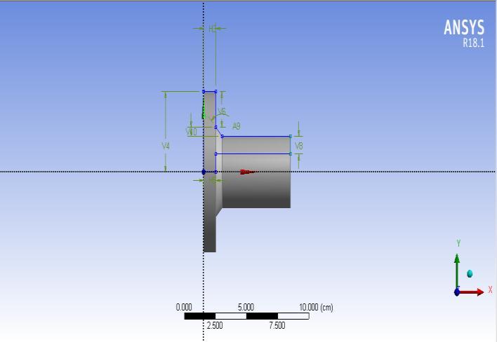
Figure4.1:a>Quartermodelb>Parametersdefinition[27]
TheCADmodelofgeometryisdevelopedasperliterature [27] using ANSYS design modeler. Initially sketch is developedasshownbybluecolouredcrosssectioninfigure 4.1above.Thedimensionsaredefinedaspertable4.1above. Thesketchisthenrevolvedto3600 angletodevelopedfull model.
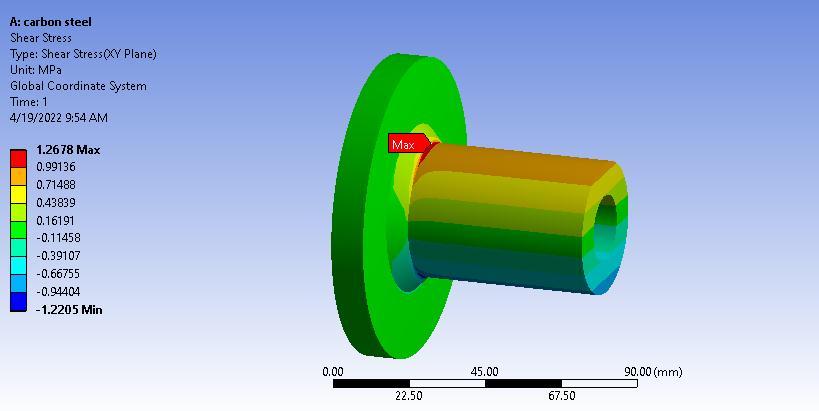
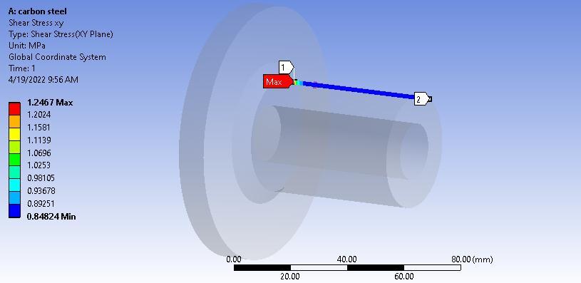
ThecarbonsteelweldjointisthesubjectoftheFEAanalysis. The shear stress plot for a carbon steel weld is generated and can be seen in figure 1.2678MPa. It is largest at the corners(theredzone),anditdecreasesalongthelengthof thetube.
Figure5.2:Shearstressplotforcarbonsteel
International Research Journal of Engineering and Technology (IRJET) e ISSN: 2395 0056
Volume: 09 Issue: 07 | July 2022 www.irjet.net p ISSN: 2395 0072
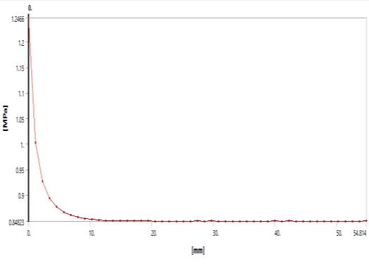
The shear stress value is plotted along the curve on tube region as shown in figure 5.5 above. The maximum shear stressisobservedattheintersectionregionwithmagnitude of1.2467MPawhichreducesalongthelength.Thevariation ofshearstressalongthelengthisshownincurve(figure5.6 below).
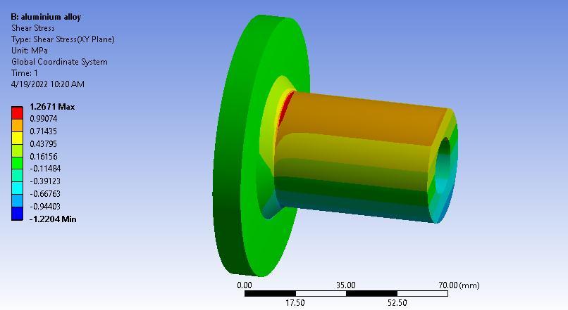
TheFEAanalysisisconductedonaluminiumalloyweldjoint. Theshearstressplotisgeneratedforaluminiumalloyweld as shown in figure 1.2671MPa which is maximum at the cornerregions(redcoloredregion)anditreducesalongthe lengthoftube.
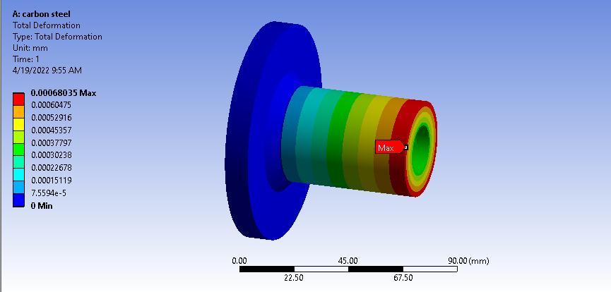
The maximum deformation is observed at the free end of tubewithmagnitudeof.00068mmanditreducestowards thesupportedendwhichisshownindarkbluecolor.
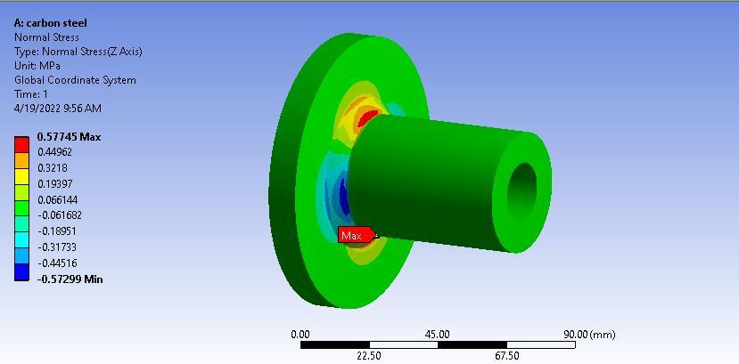
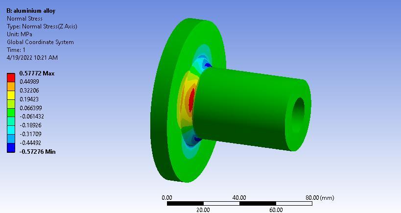
The normal stress plot is generated for carbon steel tube flangeweldjointasshowninfigure5.4above.Themaximum normalstressof.57745MPaisobservedattheintersection.
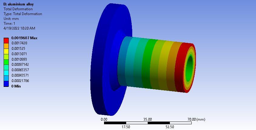
The maximum deformation is observed at the free end of aluminiumalloytubewithmagnitudeof.0019607mmandit reducestowardsthesupportedendwhichisshownindark bluecolor.
International Research Journal of Engineering and Technology (IRJET) e ISSN: 2395 0056
Volume: 09 Issue: 07 | July 2022 www.irjet.net p ISSN: 2395 0072
The normal stress plot is generated for carbon steel tube flangeweldjointasshowninfigure5.9above.Themaximum normalstressof.5777MPaisobservedattheintersection.
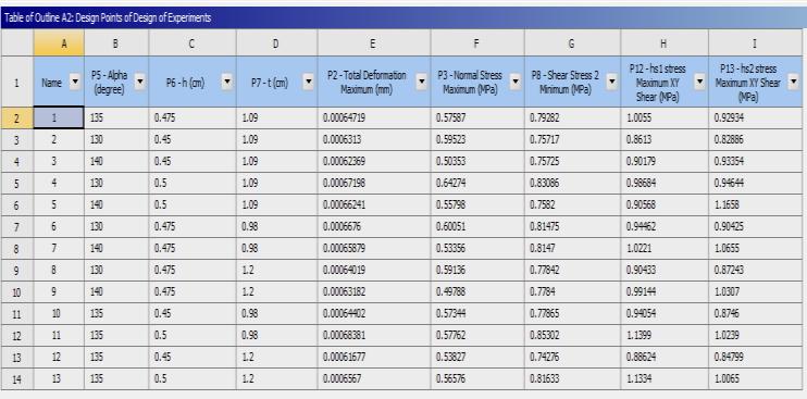
Using Taguchi response surface (DOE) method involving centralcompositedesignschemevariousdesignpointsare generated.Thestress,deformationcorrespondingtothese designpointsareevaluatedfromFEAanalysis.Thecompiled results are shown in table 5.2 above. The maximum and minimumvaluesobtainedfromdesignofexperimentsare shownintable5.3below.
ANSYS software is used to do the FEA study of the weld geometry,and the resultsareanalyticallyvalidated.Using response surface methods and design of experiments, the shape of the weld parameters is optimized. Plots of the response surface are produced for shear stress and deformation.Therangeofmagnitudeoftheparameters(h,, andt)forthehighestandminimumvaluesofshearstress, deformation, and safety factor can be calculated using responsesurfaceplots.Herearethespecifics:
The shear stress value is plotted along the curve on tube regionasshowninfigure5.10above.Themaximumshear stressisobservedattheintersectionregionwithmagnitude of 1.24676MPa which reduces along the length. The variationofshearstressalongthelengthisshownincurve.
The design points are generated from Taguchi design of experimentsisshownintable5.2below.
1.Becausethecornerpointdevelopsthemostshearstress,it is extremely prone to fatigue failure. For carbon steel, the amountofstresscreatedatthecorneris1.2678MPa.
2.Theshearstressvs.distancecurvefiguredemonstrates that the shear stress drops as one moves away from the cornerandbecomesnegligibleasonemovesneartheend, whereasthedeformationisgreatestattheopenend.
3. The alpha's sensitivity to overall deformation is 11.324 (negative). The negative sensitivity indicates that total deformationwoulddecreaseasalphavalueincreasedand viceversa.
4. The h variable's sensitivity to overall deformation is 52.495(positive).Thepositivesensitivityindicatesthatthe overalldeformationwouldrisewithanincreaseinhvalue andviceversa.
5.Thet'ssensitivitytototaldeformationis35.949(negative). A negative sensitivity indicates that overall deformation woulddecreaseashvalueincreasedandviceversa.
International Research Journal of Engineering and Technology (IRJET) e ISSN: 2395 0056
6. The alpha's sensitivity to typical stress is 58.763 (negative).Thenegativesensitivityindicatesthatdecreasing normalstresswouldoccurwithanincreaseinalphavalue andviceversa.Thehvariablerespondspositively(34.376) toordinarystress.
[1]Olsson,C.,2005.Konstruktionshandbokförsvetsadeprodukt er.3ed.Lidingö:Industrilitteratur.
[2]Olsson,C.,2014.Konstruktionshandbookförsvetsadeprodu kter.5ed.Onsala:TechstratPublishing.
[3] T. Ninh Nguyen and M. A. Wahab, “The effect of weld geometryandresidualstressesonthefatigueofweldedjoint undercombine
[4]KyungwooLee,“Largedeflectionsofcantileverbeamsof nonlinear elastic material under a combined loading,” International Journal of Non Linear Mechanics 37 (2002) 439 443.
[5]RobbC.Wilcox,“Theeffectofweldpenetrationontensile strengthoffilletweldedjoints”,B.S.,NavalArchitectureand Marineengineering,U.S.coast guardacadamy,1991
[6]Mahapatra,M.,G.L.Datta,B.Pradhan,andN.R.Mandal. “Modellingtheeffectsofconstraintsandsingleaxiswelding processparametersonangulardistortionsinone sidefillet welds.”Proc.IMechE221PartB:397 407.
[7] Kumose, T., T. Yoshida, T. Abbe, and H. Onoue. “PredictionofAngularDistortionCausedbyOne PassFillet Welding.”WeldingJournal.1954:945 956.
[8]Michaleris,P.,J.Dantiz,andD.Tortorelli."Minimization ofweldingresidualstressanddistortioninlargestructures." WeldingJournal11(1999):361 366s.
[9] Okerblom, N.O. "The Calculations of Deformations of WeldedMetal Structures."1958(HerMajesty’sStationery Office,London).
[10] Teng, T., and C. Lin. “Effect of welding conditions on residualstressesduetobuttwelds.”InternationalJournalof PressureVesselsandPiping75(1998):857 864.
[11] Teng, T., C. Fung, P. Chang, and W. Yang. Analysis of Residual Stresses and Distortions in TJoint Fillet Welds. International Journal of Pressure Vessels and Piping 78 (2001):523 538.
[12]Tekriwal,P.,andJ.Mazumder."TransientandResidual Thermal Strain Stress Analysis of GMAW."Journal of EngineeringMaterialsandTechnology113(1991):336 343.
[13] T. Lassen, ph. Darcis, and N. Recho,(2005) Fatigue behavior of welded joints part 1 Statistical methods for
fatigue life prediction supplement to the welding journal, SponsoredbytheAmericanWeldingSocietyandtheWelding ResearchCouncil,pp.183 187.
[14]TeppeiOkawa,HiroshiShimanuki,TetsuroNose,Tamaki Suzuki,(2013)Fatiguelifeprediction ofweldedstructures based on crack growth analysis, Nippon steel technical reportno.102,pp.51 53.
[15]Multipleobjectiveoptimizationofadieselenginefueled withKaranjabiodieselusingresponsesurfacemethodology PurushottamKumarSahu aSatyendraSharmab https://doi.org/10.1016/j.matpr.2021.12.206
Volume: 09 Issue: 07 | July 2022 www.irjet.net p ISSN: 2395 0072 © 2022, IRJET | Impact Factor value: 7.529 | ISO 9001:2008 Certified Journal |