International Research Journal of Engineering and Technology (IRJET)
e-ISSN: 2395-0056
Volume: 09 Issue: 07 | July 2022
p-ISSN: 2395-0072
www.irjet.net
Design of a Wideband 8x8 MIMO Microstrip Patch Antenna for 5G Applications Kalpita B Velip1, Ameeta G Sinai Amonkar2 1 Student, Dept. of Electronics and Telecommunication Engineering, Goa Engineering college, Goa, India
2 Professor, Dept. of Electronics and Telecommunication Engineering, Goa Engineering college, Goa, India
---------------------------------------------------------------------***---------------------------------------------------------------------
Abstract - In the Recent technology development most of
The microstrip slotted antennas are used for miniaturization, low profile, inexpensive, lightweight, simplicity, low profile and reproducibility.
the used antennas are low-profile antennas elements with Multi-Input Multi-Output (MIMO) antenna array is presented for 5G devices. The paper focusses on the system that can operate at a wideband range that covers 4.9–6.2 GHz. Desirable antenna wideband capability is obtained by introducing slots in the patch where the overall antenna size is (46.42 mm × 46.42 mm). The technique of band enhancement of creating slots in the antenna is used so far. The simulated results of the presented paper of MIMO antenna array show that in the achieved wide band, the proposed design can achieve good antenna performances, with isolation >16 and return loss <-11dB are calculated. The antenna gain and radiation pattern are demonstrated. The proposed Multi-Input Multi-Output (MIMO) antenna system presents small size, simple design and wider bandwidth. This MIMO antenna parameters have been studied with the HFSS software to obtain a better output.
By using open ended and closed ended slots band enhancement and compactness is achieved. It also helps in impedance matching, gain enhancement, isolation and for shifting the frequency at desired frequency. The reflection coefficients of the antenna design is evaluated to be less than −11 dB across 4.9–6.2 GHz, with isolation greater than 16 dB. The S parameters, radiation performances (radiation pattern, total efficiency and gain) are investigated. ANSYS HFSS is used to obtain the simulated results.
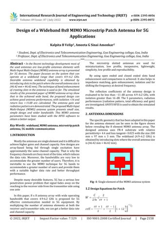
2. ANTENNNA DIMENSIONS The specific geometry that has been adapted in this paper for the antenna element can be seen in the figure shown below revealing the 8 element MIMO antenna array. The designed antenna uses FR-4 substrate with relative permittivity= 4.4 and loss tangent= 0.025 with the size 200 mm x 97 mm x 3 mm. The wideband (4.9–6.2 GHz) is obtained by introducing slots where the overall antenna size is (46.42 mm × 46.42 mm).
Key Words: wideband, MIMO antenna, microstrip patch antenna, 5G mobile communication
1.INTRODUCTION Mostly the antennas are single element and it is difficult to achieve higher gains and channel capacity. Few designs are array-based being fed through single excitation have approximately the same channel capacity. That is why the frequency channels are busy most of the time, which reduces the data rate. Moreover, the bandwidths are very low to accommodate the greater number of users. Therefore, it is inevitable to use the MlMO technique for 5G bands to accommodate a greater number of users and provide them with a suitable higher data rate and better throughput performance. Despite many desirable features, 5G has a serious low penetration power problem that signal fades away on the reaching to the receiver side from the transmitter side using one ante
Fig -1: Single element of the MIMO antenna system
1.2 Design Equations for Patch
In this paper, 8 x 8 antenna array with wide operating bandwidth that covers 4.9-6.2 GHz is proposed for 5G effective communication needed in 5G equipment. By multiplying the number of antenna elements at both the receiver and transmitter side, we can get a better data rate and channel capacity.
© 2022, IRJET
|
Impact Factor value: 7.529
|
ISO 9001:2008 Certified Journal
|
Page 2158
International Research Journal of Engineering and Technology (IRJET)
e-ISSN: 2395-0056
Volume: 09 Issue: 07 | July 2022
p-ISSN: 2395-0072
www.irjet.net
isolation between the pair of the antenna elements is more than 16 dB.
Where, w =width of the patch L =length of the patch
Fig -3: Simulated S11 parameter
F =Resonant frequency
4.2 Radiation Performances
εr =Dielectric constant of substrate
The MIMO antenna is simulated with the HFSS software which shows the result in the x and y direction which can be shown in fig.4 at 3.5 GHz and fig.5 at 6 GHz. As can be seen from both the figures the radiation is almost unidirectional. . The simulated 3D patterns at the frequencies 3.5 GHz, 5 GHz and 6 GHz are shown in fig. 6, fig.7 and fig.8.
3. DESIGN AND CONSTRUCTION In the fig 1 the specific structure of the antenna element is shown. The overall square patch is 46.42 mm2. A close ended and an open ended slot is etched of the shape revealed in the fig 1 which acts as the dipole to extend the band. The width of the feed line was designed to be 50 ohms for probe feeding. The antenna is inset fed. The MIMO Antenna array is designed using the 8 single elements on FR-4 substrate with relative permittivity of 4.4 and loss tangentof 0.025 as shown in the fig 2 below.
Fig -4: Simulated radiation pattern in the xy plane at 3.5 GHZ
Fig -2: The proposed design of 8x8 MIMO Antenna
4. RESULTS AND DISCUSSION
Fig -5: Simulated radiation pattern in the xy plane at 6 GHZ
4.1 S Parameter Using the HFSS the results of the proposed antenna structure have been simulated. It can be seen in fig 3 that each element can cover the bandwidth from 4.9 to 6.2GHz with return loss less than -11 dB. A return loss of -11.5 dB and 13 dB is observed at 5GHz and 6GHz respectively. The
© 2022, IRJET
|
Impact Factor value: 7.529
|
ISO 9001:2008 Certified Journal
|
Page 2159
International Research Journal of Engineering and Technology (IRJET)
e-ISSN: 2395-0056
Volume: 09 Issue: 07 | July 2022
p-ISSN: 2395-0072
www.irjet.net
ACKNOWLEDGEMENT My gratitude towards the Principal and H.O.D, Dept. of Eelectronics and telecommunications, Goa college of Engineering and the guide Prof. Ameeta G Sinai Amonkar is expressed.
REFERENCES Fig -6: Simulated 3D Gain at 3.5 GHz
Fig -7: Simulated 3D Gain at 5 GHz
Fig -8: Simulated 3D Gain at 6GHz
[1]
Qinyi Cai, Yixin Li, Xugang Zhang, and Wenhui Shen ‘‘Wideband MIMO antenna array covering 3.3-7.1 GHz for 5G metal-rimmed smartphone applications’’ IEEE Access, vol. 6, pp. 28041–28053, 2018.
[2]
Qualcomm. Making 5G NR a Commercial Reality. Accessed: Mar. 2019
[3]
Technical Specification 38.101-1: NR; User Equipment (UE) Radio Transmission and Reception; Part 1: Range 1 Standalone.
[4]
H. Zou, Y. Li, C.-Y.-D. Sim, and G. Yang, ‘‘Design of 8×8 dual-band MIMO antenna array for 5G smartphone applications,’’ Int. J. RF Microw. Comput. Aided Eng., vol. 28, no. 9, Nov. 2018, Art. no. e21420.
[5]
Y. Li, C.-Y.-D. Sim, Y. Luo, and G. Yang, ‘‘12-Port 5G massive MIMO antenna array in Sub-6GHz mobile handset for LTE bands 42/43/46 applications,’’ IEEE Access, vol. 6, pp. 344–354, 2017.
[6]
H. Zou, Y. Li, B. Xu, Y. Luo, M. Wang, and G. Yang, ‘‘A dualband eight-antenna multi-input multi-output array for 5G metal-framed smartphones,’’ Int. J. RF Microw. Comput. Aided Eng., vol. 29, no. 7, Jul. 2019, Art. no. e21745.
[7]
C. Huang, Y.-C. Jiao, and Z.-B. Weng, ‘‘Novel compact CRLH-TL-based tri-band MIMO antenna element for the 5G mobile handsets,’’ Microw. Opt. Technol. Lett., vol. 60, no. 10, pp. 2559–2564, Oct. 2018.
[8]
Y. Li, C.-Y.-D. Sim, Y. Luo, and G. Yang, ‘‘Multiband 10antenna array for sub-6 GHz MIMO applications in 5-G smartphones,’’ IEEE Access, vol. 6, pp. 28041–28053, 2018.
[9]
H. Shi, X. Zhang, J. Li, P. Jia, J. Chen, and A. Zhang, ‘‘3.6GHz eightantenna MIMO array for mobile terminal applications,’’ AEU Int. J. Electron. Commun., vol. 95, pp. 342–348, Oct. 2018.
Table -1: Simulated return loss and gain at different frequencies Return loss and Gain at different frequencies Frequency
Return loss (dB)
Gain (dB)
3.5 GHz
-4.5 dB
1.2 dB
5 GHz
-11.5 dB
4.3 dB
6 GHz
-13 dB
4.6 dB
5. CONCLUSIONS A 8x8 element wideband (4.9–6.2 GHz) MIMO antenna has been designed using 8 single 46.42 mm2 slotted microstrip line fed planar patch antennas on FR-4 substrate of the size 200 mm x 97 mm x 3 mm. Impedance matching and close ended and open ended slot is used designing to achieve frequency adjustment, compactness and good performance. The bandwidth of 1.3 GHz, covering 4.9–6.2 GHz band with 4.6 dBi peak gain of the antenna, isolation >16 dB and return loss <-11dB is achieved. This antenna design of array can be used for 5G communication to various applications.
© 2022, IRJET
|
Impact Factor value: 7.529
[10] I. R. R. Barani and K.-L. Wong, ‘‘Dual-feed U-slot antenna
having low envelope correlation coefficients for the LTE MIMO operation in the metal-framed smartphone,’’ Microw. Opt. Technol. Lett., vol. 60, no. 2, pp. 295–302, Feb. 2018.
|
ISO 9001:2008 Certified Journal
|
Page 2160
International Research Journal of Engineering and Technology (IRJET)
e-ISSN: 2395-0056
Volume: 09 Issue: 07 | July 2022
p-ISSN: 2395-0072
www.irjet.net
[11] I. R. R. Barani and K.-L. Wong, ‘‘Integrated inverted-f and
open-slot antennas in the metal-framed smartphone for 2×2 LTE LB and 4×4 LTE M/HB MIMO Operations,’’ IEEE Trans. Antennas Propag., vol. 66, no. 10, pp. 5004–5012, Oct. 2018. [12]
A. Zhao and Z. Ren, ‘‘Wideband MIMO antenna systems based on coupled-loop antenna for 5G N77/N78/N79 applications in mobile terminals,’’ IEEE Access, vol. 7, pp. 93761–93771, 2019. 142082 VOLUME 7, 2019 Q. Cai et al.: Wideband MIMO Antenna Array Covering 3.3–7.1 GHz for 5G Metal-Rimmed Smartphone Applications
[13] H. Xu, H. Wang, S. Gao, H. Zhou, Y. Huang, Q. Xu, and Y.
Cheng, ‘‘A compact and low-profile loop antenna with six resonant modes for LTE smartphone,’’ IEEE Trans. Antennas Propag., vol. 64, no. 9, pp. 3743–3751, Sep. 2016.
[14] Technical Report 37.890: Feasibility Study on 6 GHz for
LTE and NR in Licensed and Unlicensed Operations. [15] Technical Report 38.889: Study on NR-Based Access to
Unlicensed Spectrum. [16] H. Wang, D. Zhou, L. Xue, S. Gao, and H. Xu, ‘‘Modal
analysis and excitation of wideband slot antennas,’’ IET Microw. Antennas Propag., vol. 11, no. 13, pp. 1887– 1891, Oct. 2017. [17] ] M. Zheng, H. Y. Wang, and Y. Hao, ‘‘Internal hexa-band
folded monopole/dipole/loop antenna with four resonances for mobile device,’’ IEEE Trans. Antennas Propagation., vol. 60, no. 6, pp. 2880–2885, Jun. 2012.
© 2022, IRJET
|
Impact Factor value: 7.529
|
ISO 9001:2008 Certified Journal
|
Page 2161