(IRJET)

e ISSN: 2395 0056
ISSN: 2395 0072
(IRJET)
e ISSN: 2395 0056
ISSN: 2395 0072
1 Department of Biomedical Engineering and Environmental Science, National Tsing Hua University, Hsinchu, Taiwan
2 Institute of Nanoengineering and Microsystem, National Tsing Hua University, Hsinchu, Taiwan
3Department of Biomedical Engineering, SRM Institute of Science and Technology, Kattankulathur, India
4 Department of Medicine, Gayatri Vidya Parishad Institute of Health Care and Medical Technology, Visakhapatnam, India
***
Abstract Total hip replacement (THR) is an effective procedure which relieves pain and helps regain the functionality of degenerated femur bones, which might have occurred due to osteosarcoma, bone fracture, revision arthroplasty, or accidents. There are multiple factors which are responsible for the success of an implant which includes implant design, mechanical stability, osseointegration, and a patient’s immunological responses, etc. But the most important factor is design of the implant and its mechanical stability. The mechanicalstabilityofanimplantdeterminesits durabilityandlife. The implant designdeterminesthestability as it plays a significant role in appropriate fixation and osseointegration. We have used different models and experimental analysis to determine the mechanical characteristics of the total hip implant for different individuals, developing isotropous and aeolotropic models oriented to determine the mechanical activity of the total hip implant. These models give us important information about the resistance of the hip implant, thereby allowing us to predict its functionality in real time. Images from CT scans of healthy individuals have been utilized to analyze the morphology. CT images are extracted using mimics software and were converted to STL file and was used for obtaining the dimensions of the femoral bone, and these dimensions were used to design a patient specific hip implant. It was designed using Auto CAD software. FEA method was used to test the mechanical strength of different materials. The dimensions, mass, and volume ofthe femur bone as well as the angle of the femoral head vary from person to person thereby making it necessary to design a patient specific implant to suit personal need and requirements.
Key Words: Total hip replacement, Finite Element Analysis, CAD, Mimics, ANSYS, Patient Specific Implant
Tothisday,hipreplacementshavebeenaverycomplexand arduous process. The implants used in this particular procedure are often not compatible with the patients and causediscomfortduringtheirday to dayactivities.Ouraimis
to create a patient specific hip implant which suits the specific requirements of effected individual. A hip replacementimplantisusedwhenapersonissufferingfrom osteosarcoma, femoral neck fractures, and revision arthroplasty[1].Revisionarthroplastyisperformeddueto inappropriateprosthesisdesign,incompatiblematerialsand inappropriatesurgicalandfixationmethods[1,2].Ahipjoint fracture may occur due to various reasons such as osteoporosis (low bone density), accidents, falling from a height,andsometimesduetodiseasessuchasarthritis[1]. Peopleaffectedbyhipfractureswouldnotbeabletoleada normalandhealthylifeduetoseverepainandimmunological responses. Thus, in order to lead a healthy and normal lifestyle, the patient has toundergo an arthroplasty or hip replacementsurgery.Implantdesignandstructuralstrength playsa majorroleinthesuccessof anyimplant.Improper design and uneven distribution of stress over implant generallyleadslooseningoftheimplant[3]. Hencedesignis animportantaspectofanyimplantbecauseanothermajor problemfacedisthedamageofboneduringsurgery[4].The volume and density of bone present also determines the successandstabilityofimplant[5,6].
Inthisprocedure,theproximalpartofthepatient’sfemoral bone and cartilage (the diseased or affected tissue) is surgically replaced with an implant [7]. The affected individualsfaceinaccuratedimensionsintheimplant,which causes difficulties in their day to day life. The present day implantsuseacommonmaterialforeveryindividual,buta differentmaterialisuseddependingonthesize,shape,and weightoftheindividual.Thesizeofthefemurbonevariesfor eachindividual.
Ifhealthy,ahumanoranimal’sboneswillhavetheabilityto changetheirvulnerabilitytowardsdifferentamountsofloads which are placed on them. When the amount of load increasesthebonesofthehumanoranimalwillalterthemin suchawaythatit’sstrengthalsoincreasestohandletheload and vice versa [8]. Initially, there is an alteration in the structureofthetrabeculaebone,aswellasamodificationin theexternalcorticalboneportion,thiscausestheentirebone toincreaseinitsthickness.Similarly,iftheboneisnotloaded
9001:2008
Thrinayan Moorthy1,*, Shubhanvit Mishra2,*, Mohamed Hathim B3, Palla Deshik Yadav 4 , Bhanu Nirosha Yalamandala1 , Thi My Hue Huynh1ISSN:
asmuchorgivenasmuchload,therewillbedecreaseinthe strength and thickness of the bone this phenomenon is stress shielding [9]. This can lead to a decrease in bone density, which is also known as osteopenia. Although the strengthofbonesisalteredbasedontheload,pressure,and mechanicalpropertieswhichtheyareputunderduetotheir dynamicnature,theyarealsopronetoalterationsbasedon changesintheirhormonesandmetabolicstates.Theprocess of bone homeostasis is depicted in situations where the bone’s density and strength decrease when it is not being influenced by and loads, or found in a ‘weightless’ surrounding. Similarly, after an individual experience an injurywhichdoesnotallowthemtousetheirbones,theyfind thattheirbonesbecomeweakerthanbefore,duetothelack ofloadplacedonit.Henceitisveryessentialfortheimplant to mimic the properties of bone in order to withstand the adequateloadwhichwouldin turnpreventthelooseningof implantandpreventrevisionarthroplasty[10].
Apatient specifichipimplantwasdesignedaccordingtothe requirements and needs of the patient. We measured the dimensionsofthefemuroftheaffectedindividualusingaCT scanner.TheCTdatawasextractedusingMimicstoobtaina 3Dmodelofthefemurbone.AutoCADwasusedtodesign the patient specific implant. ANSYS software was used to carry out finite element analysis (FEA) on the designed implantforvariousmaterials.Bycarryingoutastructural analysisofthedesignedimplant,wecangettoknowabout themechanicalstrengthofthedesignedimplantforvarious materials. This pre simulation of the hip implant is very usefulindeterminingthestabilityandcompatibilityofthe implant to be placed into the patient’s body. The femur is one of the strongest bones of the human body. Hence, replacing the proximal part of the femur bone with an appropriateimplantisverycrucialandnecessaryinorderto overcometheproblemofrevisionarthroplasty,whichisa verypainful,timeconsuming,andanexpensiveprocedure. Inordertoovercometheseproblems,itisbettertosimulate the loading and unloading stress on the designed femur implant. The stability of the implant can be increased by addingporesinitinordertofacilitatethemovementofthe cellsandplasmafluidthroughit,whichmayinturn,leadto thegrowth ofnewcells,aswell as newtissuegrowthand formation. Hence, we performed FEA on the two femur modelsoftheimplantinwhichonewasnormalwithoutany pores(NWP),onewithporesofvaryingdiameter(oneatthe proximalendandtheotheratthedistalend).Theholeswere placed a few centimeters below the neck of the proximal femoral implant. The comparison of the models with and without pores has been shown in the result. The general materials used for the pre simulation of implants include Stainless Steel, Titanium alloy (Ti6Al4V) and Elgiloy. The overallcomparisonsofmechanicalstrengthofthematerials and designs have been tabulated and represented graphicallyintheresultsection.
ThetotalfemurboneCTmodelwasdevelopedusingMIMICS software as shown in Figure 1 (Materialise). Materialise Mimicsisanimageprocessingsoftwarefor3Ddesignsand modeling.ACTimageofthefemurwasusedtodesignthe patient specific total femur replacement model which providedadimensionfortheimplanttobedesigned.Atotal of two 3D models of the femur bones were extracted and stored as STL.files. The femur was measured and its dimensionswereobtained.Boththe3Dmodelsofboneswere takenfromhealthyindividuals.Aninbuiltsoftwarecalled3D builderwasusedtoopenthe3Dmodelofthefemurbone. Mimicswereusedtomeasurethedimensionsofthefemur bone.Themeasureddimensionswereaveragedandthenthe resultantdimensionswereusedtodesigntheimplant.
The hip implant was designed using AutoCAD software. AutoCADisamercantilecomputer aideddesign(CAD)and draftingengineeringsoftware.Thedimensionsofthefemur bone were measured using the 3D model obtained using mimics. In this research, a total of two implants were designed as shown in Figure 2. The designed hip replacementimplantmodelsaresavedas‘iges.file’format. Boththeimplantmodelshaveafemoralstemlengthofabout 8.2cm,butthehead(ball)diametersvaryinboththedesigns [11].Design‘1’hasafemoralhead(ball)diameterof2.3cm and design ‘2’ has a femoral head diameter of 3cm [12]. Design‘2’hasporesattheproximalanddistalendinorder tofacilitateosseointegration.Theporeattheproximalend hasadiameterof 7mm,andtheporeatdistalendhasaof diameter5mm.Theporeswerecutthroughtheimplantina horizontalplaneinvaryingdiameters.
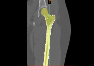 Fig 1: ProximalFemurbonesegmentedusingMimics Software
Fig 2: THRmodelsproducedwithvaryingdesignusing AutoCAD
ThedesignedimplanthasbeentestedusingANSYS. ANSYS softwareisusedtodesign3Dmodelsandobjects,aswellas to perform simulations that test a product's endurance, distribution of temperature, fluid dynamics, and electromagneticcapability.Thedesignedimplantwastested foritsstaticstructuralanalysisinANSYS.Itcarriesoutthe FEA method, which is a numeric method for solving the engineering and mathematical physics problems and equations. The implant models were imported into ANSYS 18.1iniges.fileformat.Theimplantmodelsweretestedfor theirmechanicalstrength.Themodelswereexaminedforthe material Ti6Al4V, Stainless Steel, and Elgiloy. Ti6Al4V is widelyusedforthefabricationofvariousimplants,andisthe moststablematerial;italsopromotesosseointegration[13]. The femoral stem was given as fixedsupport.Forces were appliedontheimplantsheadfrom‘3’differentaxis.Thejoint contactforcesappliedwere‘x’axis 433.8N,‘y’axis 263.8N, ‘z’axis 1841.3N[14].
ISSN: 2395
ISSN:
Fig -3: Von Mises Stress result of THR Design-2 of Egiloy materialobtainedbyAnsys
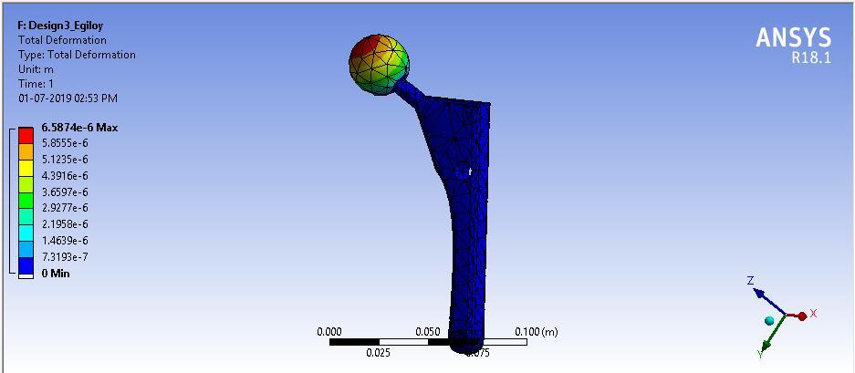
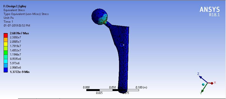
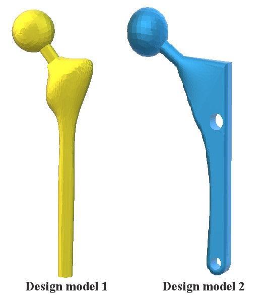
Fig -4: TotalDeformationsFiniteElementAnalysisresult ofTHRDesign-2ofEgiloymaterialobtainedbyAnsys
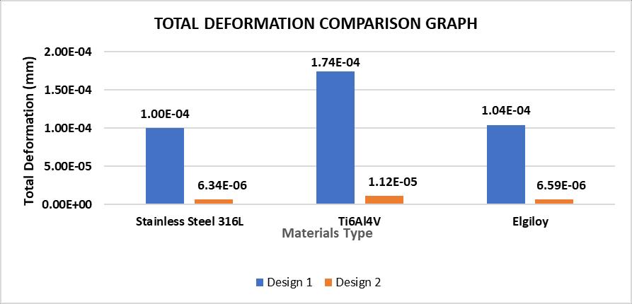
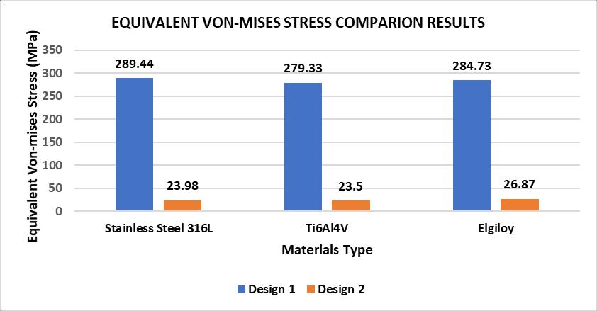
Finiteelementanalysisisusedtotestcompressiveand effectivetensilemodulus ofdifferentstentgeometriesand shapes.TheFiniteelementanalysisdatagenerallyhasa30% error.Theresultwasobtainedandanalysedintermsofvon misesstressandtotaldeformation.Theproximalpartofthe implant(neckoftheimplant)experiencedhighermagnitude of stress. The medial and distal part of the implant experienced the minimum amount of stress as shown in Figure 3. The von mises stress and total deformation are tabulatedandagraphhasbeenplottedforthesame.
Table 1: TotalDeformationsin(mm)valuesobtained byFEAanalysis
Stainless Steel 316L Ti6Al4V Elgiloy
Design 1 100E04 174E04104E04 Design 2 634E06 112E05659E06
Chart -1:TotalDeformationscomparisonresultobtainedby FEAanalysis
Table 1: EquivalentVon misesStress(MPa)values obtainedbyFEAanalysis
Stainless Steel 316L
Ti6Al4V Elgiloy
Design 1 289.44 279.33 284.73
Design 2 23.98 23.5 26.87
InthisstudytwohipprosthesisweredesignedandFEAwas performedtodeterminetheirmechanicalstability.Inboth theimplantsmaximumdeformationwasobservedattheball region.Maximumdeformationwasnoticedattheballregion because joint contact force was applied on to the ball directly.Slightlyhighstresswasobservedattheneckregion. Thishasbeenattributedtothethindesignoftheneck.The stems of both implants experienced the least amount of stress and underwent minimum of deformation. The magnitude of stress varied from the head region to the femoralstemregion.Thewholestressdistributionwaseven throughout the implant which is essential for osseointegration(bonegrowth)andfortheimplanttostay intactinthefemoralbone.Themagnitudeofstressvaried drastically between both the implants. Design 1 shows
(IRJET)
e ISSN: 2395 0056
ISSN:
highermagnitudeofstresswhencomparedtodesign2,but when it comes to total displacement design 2 showed the least amount of deformation when compared to design 1. Thisisduetoathickerstemindesign2.Notmuchdifference was observed in the magnitude of stress when compared withdifferentmaterialsusedinthestudy.Elgiloyisanew materialwhichisextensivelyusedforthemanufacturingof implantsduetoitspropertiessuchascorrosionresistance andhighstrength[15].
FEAisadependablemethodwhichcanbeimplementedin implant analysis and testing to determine the mechanical stabilityofanyimplant.Themajorobjectivewastolowerthe stressanddisplacementwhichhasbeenachievedindesign ‘2’bymakingporesandprovidingacurvedneck.
[1]Ridzwan,M.I.Z.,Shuib,S.,Hassan,A.Y.,Shokri,A.A.,& Ibrahim, M. M. (2007). Problem of stress shielding and improvement to the hip implant designs: a review. J. Med. Sci, 7(3),460 467.
[2]Derar,H.,&Shahinpoor,M.(2015).Recentpatentsand designsonhipreplacementprostheses. Theopenbiomedical engineering journal, 9,92.
[3]Shuib,S.,Sahari,B.,Shokri,A.A.,&Chai,C.S.(2008).The design improvement of hip implant for Total Hip Replacement(THR). Jurnal Kejuruteraan, 20,107 113.
[4]Colic,K.,&Sedmak,A.(2016).Thecurrentapproachto research and design of the artificial hip prosthesis: a review. Rheumatol Orthop Med, 1,1 7.
[5] Abraham, R., & Malkani, A. L. (2005, June). Instability aftertotalhipreplacement.In Seminars inArthroplasty (Vol. 16,No.2,pp.132 141).WBSaunders.
[6] Viceconti, M., Brusi, G., Pancanti, A., & Cristofolini, L. (2006). Primary stability of an anatomical cementless hip stem: a statistical analysis. Journal of biomechanics, 39(7), 1169 1179.
[7]Zagra,L.(2017).Advancesinhiparthroplastysurgery: whatisjustified?. EFORT open reviews, 2(5),171 178.
[8]Ruff,C.,Holt,B.,&Trinkaus,E.(2006).Who'safraidofthe big bad Wolff?:“Wolff's law” and bone functional adaptation. American Journal of Physical Anthropology: The Official Publication of the American Association of Physical Anthropologists, 129(4),484 498.
[9] Sumner, D. R. (2015). Long term implant fixation and stress shielding in total hip replacement. Journal of biomechanics, 48(5),797 800.
[10]Park,J.B.(2000).Hipjointprosthesisfixation:problems andpossiblesolutions. Biomedical Engineering Handbook.
Chart 2:EquivalentVon misesStress(MPacomparison resultsobtainedbyFEAanalysis
Volume: 09 Issue: 04 | Apr 2022 www.irjet.net
[11] Kim, J. T., & Yoo, J. J. (2016). Implant design in cementlesshiparthroplasty. Hip & pelvis, 28(2),65 75.
[12]Tsikandylakis,G.,Mohaddes,M.,Cnudde,P.,Eskelinen, A.,Kärrholm,J.,&Rolfson,O.(2018).Headsizeinprimary totalhiparthroplasty. EFORT open reviews, 3(5),225 231.
[13]Colic,K.,Sedmak,A.,Grbovic,A.,Tatic,U.,Sedmak,S.,& Djordjevic,B.(2016).Finiteelementmodelingofhipimplant staticloading. Procedia Engineering, 149,257 262.
[14]Abdullah,A.H.,MohdAsri,M.N.,Alias,M.S.,&Tardan,G. (2010). Finite element analysis of cemented Hip arthroplasty:influenceofstemtapers.In Proceedings of the international Multi Conference of engineering and computer scientists
[15] https://www.elgiloy.com/wire division/wire elgiloy alloy/
Factor value: 7.529 | ISO 9001:2008 Certified
e ISSN: 2395 0056
p ISSN: 2395 0072