Airfoil plays a vital role in wing designing. The airfoil selection for the wing of unmanned aerial vehicles (UAV) helps better performance to lift. Different airfoil shapes such as symmetrical, cambered, and semi symmetrical show different natures in aerodynamic & geometrical characteristics. This research deals with the selection of airfoil for a fixed wing of micro UAV which has a lift capacity of 2.5 kg. Over 2000 airfoils of NACA, MH, G, S, E series are analyzed with aerodynamic characteristics i.e. coefficient of lift & drag (Cl & Cd), coefficient of pressure (Cp), coefficient of the moment (Cm), angle of attack (α), camber & thickness. The airfoil selection is based on better lifting capacity reducing drag. Airfoils for the selection process were available from the airfoil tools database and XFLR 5 software used for analysis. For better accuracy, 150 coordinates were selected for a curve of the airfoil. Modeling and analysis are done in Solidworks & ANSYS software resp. The best suitable airfoil is nominated by analyzing graphs and verified with an analysis model
2.1 Case Study SelectanairfoilforthemicroUAVwingliftingcapacityof2.5 kg with cruising and stalling speed 15 m/s and 10 m/s respectively.
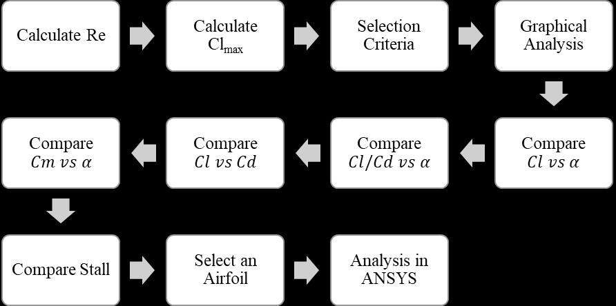
TheselectionprocessisasperFig1.Parametersoftheairfoil arecomparedi.e.(Clvsα)graph,(Cdvsα)graph,(Cl/Cdvs α)graph,(Cmvsα)graph[3].Finally,thebest chosenairfoil forthegiveninputrequirementisanalyzedinANSYS.
Key Words: Aerodynamic characteristics, Airfoils, Fixed wing, UAV, XFLR.
International Research Journal of Engineering and Technology (IRJET) e ISSN: 2395 0056 Volume: 09 Issue: 01 | Jan 2022 www.irjet.net p ISSN: 2395 0072 © 2022, IRJET | Impact Factor value: 7.529 | ISO 9001:2008 Certified Journal | Page523 SELECTION AND ANALYSIS OF AN AIRFOIL FOR FIXED WING MICRO UNMANNED AERIAL VEHICLE Ashutosh R. Kale1, Mohit S. Dhake2, Parikshit S. Deshmukh3, Babasaheb K. Varpe4 1,2,3Student, Department of Mechanical Engineering, Amrutvahini College of Engineering, Sangamner 422608 4Professor, Department of Mechanical Engineering, Amrutvahini College of Engineering, Sangamner 422608 *** Abstract
Fig. 1 Airfoilselectionprocess
1. INTRODUCTION
Anairfoilisacross sectionofthewinganditsfunctionisto producealifttotheplane.Liftisdirectlyproportionaltothe weight,theforceactsasopposedtoliftingcalleddragwhich resiststhemotionoftheplane.Theamountofweightlifted by plane depends on its application and according to that airfoil decided. Nowadays, UAVs use increases in transportation, agriculture, military, and others. Airfoil selectionforaUAVwingisthekeystepofwingdesigningto performitsfunction[1].Wingconsistsofnumbersofairfoils arejoinedonsparwithappropriatedistanceinthem.Proper selectionofairfoilisimportantasitaffectstheperformance ofwing&aircraft[2]. This work presents different characteristics, conditions, criteria andprocessesto be consideredwhileselecting an airfoil. The speed approximately defined for the cruise is about15m/sandstallabout10m/s,weightis3kgandair density1.225kg/m3.Differentairfoilshavebeenanalyzed and the best between them is selected by comparing aerodynamic parameters. This selected airfoil is used for furtherwingdesigningprocess.
2. METHODOLOGY
2.2 Selection Process
2.3 Calculate Reynolds Number (Re) Re is used to determine whether the airflow is laminar or turbulent for analyzing airfoil, Re depends on altitude, temperature, viscosity, velocity, density & mean aerodynamicchord[2]
Theobjectiveistoachievebetterliftfromanairfoilwhich willbeusedforfurtherapplications.Theresearchisaimed at selecting suitable airfoil for the construction of micro UAVs.Alltheparametersregardingairfoilaredirectlytaken fromthedatabasei.e.onlytheseparametersarecompared with respect to airfoil. Starting with Reynolds number, variousgraphsfromXFLR5arecomparedandatlastANSYS analysis is done. The procedure to use this software was studiedonline.TheprocessforselectionisshowninFig.1.

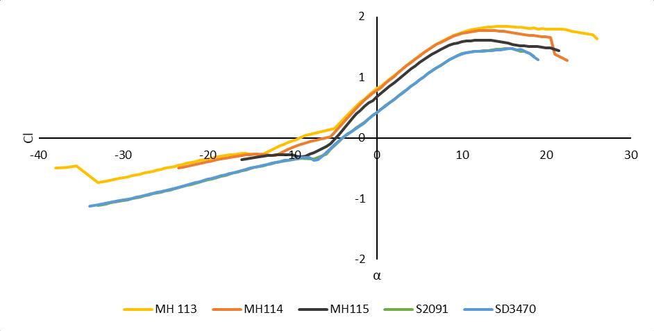
International Research Journal of Engineering and Technology (IRJET) e ISSN: 2395 0056 Volume: 09 Issue: 01 | Jan 2022 www.irjet.net p ISSN: 2395 0072 © 2022, IRJET | Impact Factor value: 7.529 | ISO 9001:2008 Certified Journal | Page524 1) Calculate Kinematic viscosity from International standardsofatmosphere(ISA): As per the conditions, Temperature (T) 15C or 288 K & Altitude(A)60m,dynamicviscosity(μ)is1.802×10 5kg⁄ms & Density (ρ) 1.225 kg⁄m3 [4], Kinematic viscosity = =1.471×10 5 m2/s.Thedynamicviscosityisdecreases withincreaseinaltitude&decreaseswithtemperature. 2)CalculateReforcruisingvelocity(Vc)andstallingvelocity (Vs)[5] Table 1 CalculationofReynoldsnumber TheairflowisturbulentasshowninTable1,LowRe canbe achievedmaximumliftcoefficient[6].UseRe range100000 to 250000 & consider Ncrit=9.0 for the batch analysis in XFLR5[7] 2.4 Calculate Clmax Firstlycalculatedwingarea afteriterationsofcalculations andthentakenforClmaxcalculationasWeight(W)=24.52N, Span(b)=1.30m,chord(c)=0.21m,aspectratio(AR)=6.19, wingsurfacearea(S)=0.2730m2,density()=1.225kg/m3 , Vc=15m/s,Vs=10m/s. (1) CalculateAircraftLiftCoefficientforcruising( ) andstalling( )[8]. 146 2 065; 2 ; 2 222 vs ClW vs ClW vs ClW s s c c (2) CalculateWingLiftCoefficientforcruising( ) andstalling( )[8] 1.53 095 2 0.68; 095 ; 095 ClClClClClW ww s c wc (3) CalculateAirfoilLiftCoefficientforcruising( ) andstalling( )[8] 1.70 090 0.75; 090 ; 090 max maxmaxmax s s c c w Cl Cl Cl Cl Cl Cl w (4) Finally,calculatetheoreticalAirfoilmaximumnet LiftCoefficient [8] 0.95 maxmaxmax sc ClClCl Finally,theairfoilparametersareshowninTable2. Table 2 Airfoilparameterwithdescription Sr.No. Parameters Description 1 Cl Maximum 2 Cd Minimum 3 Cl/Cd Maximum 4 Cm Lowest 5 Stall Smoothnature 6 Thickness&Camber Moderate 2.5 Airfoil Selection Criteria The number of airfoils are available following suitable criteriatoselectthebestairfoilforaUAVwing;forbetterlift capacity, airfoil selection keep Cl greater than theoretical Clmax, for that add 0.50 to Cl i.e. 0.50+0.95=1.45, Hence Cl should be greater than 1.45. Select airfoil with moderate camber&thicknessi.e.;cambershouldbegreaterthan5%of chord,thethicknessshouldbegreaterthan10%,&(Cl/Cd) maxshouldbegreaterthan60.Also,itshouldbestructurally reinforced&manufactured.Theαwasselectedas4 5°for fixingonthefuselage,asitprovidessafetyduetostallingi.e. from10°mostoftheairfoilstartstheirstallingregion. 2.6 Graphical Analysis NowwewillmoveforwardtowardsgraphanalysisinXFLR5 andfindoutmaximumorminimumpointandsmoothnessof curveasperourrequirement.Therearemainlyfourgraphs asexplainedbelow; 2.6.1 Cl Vs α: InFig.2αisthestallanglewhereliftefficiencywillnolonger increasewithα.Stallangleisanimportantfactorforsafety. Sr. No. Condition v (m/s) MAC (m) (m2/s) Re 1 Cruising 15 0.21 1.471×10 5 2,14,140.04 2 Stalling 10 1,42,760.02



Consideringallconstraintsfortheapplicationofplanefinally anoptimizedairfoilswereselectedfortheUAVwingafter calculationsandparametercurves.
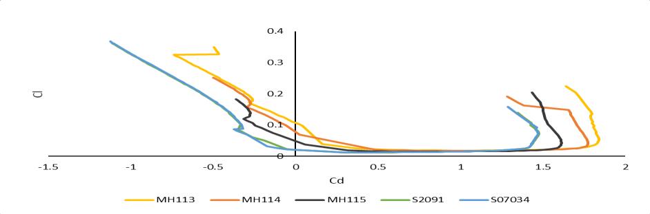
Fig. 3 GraphCmvsα 2.6.3 Cl vs Cd: The lowest point in Fig. 4 shows the minimum drag coefficient Cdmin and the corresponding lift coefficient is Clmin.TheminimumvalueofCdmin isrequiredanditranges from 0.003 to 0.006 [8]. The bucket shape of the lower regionofthegraphisauniquefeature[8].TheCdminwillnot varyforalimitedrangeofCl.Itindicatesthatapilotcanstay atthelowestdragregionhoweverchangingα[9].Hencethe pilotcandecreaseαwithoutincreasingdrag.
Airfoilhasahigherstallangle,keepsaircraftflightsafe.The stallanglerangesfrom12 to16.ZeroαatwhichCliszero. Thedesignaimistohaveahigherαgreaterthanzero.[8]
HigherClmaxresultsindecreasesstallspeedsoforsafeflight higherClmaxisrequired.Theidealcoefficientoflift(Cli)isthe Cl where Cd does not vary significantly with minor deviationsofα.Cli iscorrespondingtolowerdrag.Hereitis necessaryforlowflightcost. Theliftcoefficientatzeroangle ofattack(Cl0)istheClatαiszero.AtHigh,Cl0 isbetterto designasitcan producea positiveliftata zeroα [8]. The natureoftheCl curveatandbeyondstall angleshould be smooth.Airfoilhasagentledropintheliftafterstallleadsto saferstallfromwhichpilotcanrecover.
Fig.5 GraphCl/Cdvsα 3. RESULT
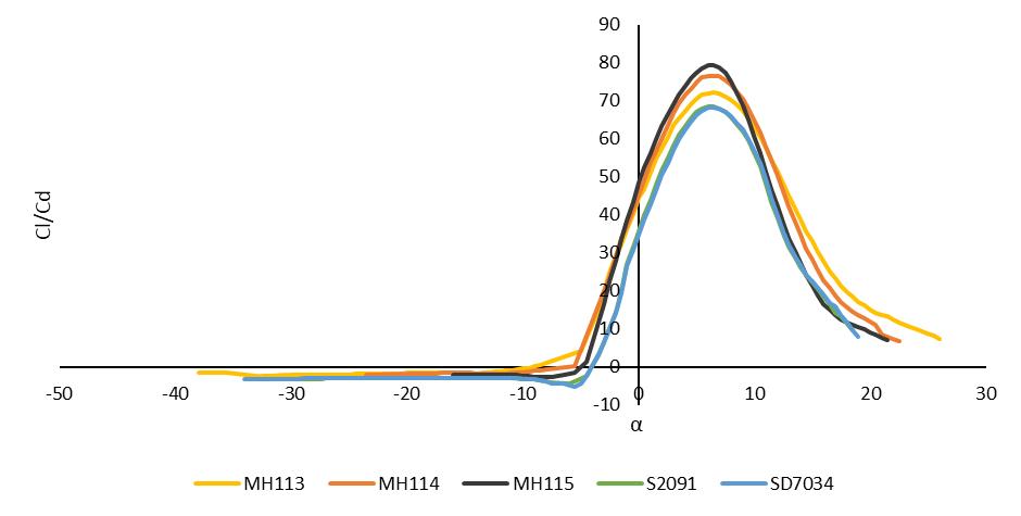
Fig. 4 GraphClvsCd 2.6.4 Cl/Cd Vs α: Fig.5hascoveredalmosteveryparameterforcomparison. At an extreme point, whether the value of the lift to drag ratio is maximum, α at this point becomes optimum. The slopeofFig.5shouldbesuchthattohaveahigherαatthe stallregion.
International Research Journal of Engineering and Technology (IRJET) e ISSN: 2395 0056 Volume: 09 Issue: 01 | Jan 2022 www.irjet.net p ISSN: 2395 0072 © 2022, IRJET | Impact Factor value: 7.529 | ISO 9001:2008 Certified Journal | Page525
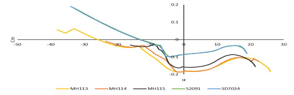
Fig. 2 GraphClvsα 2.6.2 Cm Vs α: TheslopeofFig.3isusuallynegative.Thenegativeslopeis desired, it stabilizes flight even if α is disturbed. The magnitudeofCmisconstantattherangeof 0.02to 0.05[8] ThevalueofCmisnullifiedbythetailcomponent. TheCm shouldbeclosetozeroasfaraspossibletohaveequilibrium inflight[8]
Actual
1 Airfoil 2 Wing 3 RCPlane 4. DISCUSSION Reynolds number plays an important role in analysis so calculatedforbothconditionsi.e.cruisingandstalling&Clvs No.Sr. Airfoils Clmax (Cl/Cd)max stallingAlpha Stalling 1 (MH113)113HepperleMartin 1.820 72.149 7.123 Docile 2 (MH114)114HepperleMartin 1.727 76.435 5.758 Sharp 3 (MH115)115HepperleMartin 1.588 79.484 6.037 Moderate 4 (S2091)2091Selig 1.406 68.588 6.156 Sharp 5 (SD7034)DonovanSelig 1.381 68.347 6.321 Moderate
Table
profile
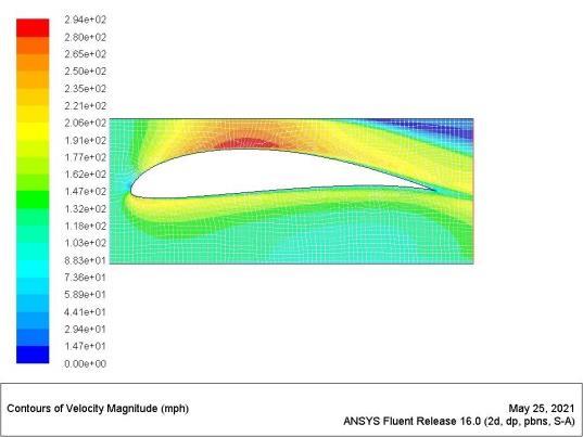
International Research Journal of Engineering and Technology (IRJET) e ISSN: 2395 0056 Volume: 09 Issue: 01 | Jan 2022 www.irjet.net p ISSN: 2395 0072 © 2022, IRJET | Impact Factor value: 7.529 | ISO 9001:2008 Certified Journal | Page526 Table 3 Observationofairfoils FromTable3,wehaveselectedaMH113forthewing.This airfoilhasasmoothdocilecurveatstallingwithmaximum Clmax.Ithasmaximum(Cl/Cd)max,soitproducesminimum dragwithhigherstallingα.AirfoilType:CamberedAirfoil, SelectedAirfoilName:MH113,Thickness:14.67%,Camber: 6.90%. Fig. 6 Velocitydistributionoverairfoilprofile
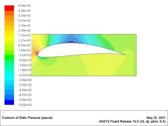
Fig.7 Pressuredistributionoverairfoil
Parts
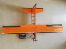
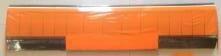
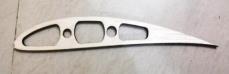
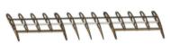
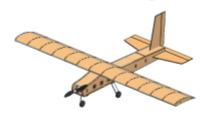
TheselectedairfoilMH113isanalyzedinANSYSatα=0°and pressureandvelocitydistributionisgeneratedasshownin Fig. 6 7. Here flow of air at upper surface and pressure distribution along the chord of the airfoil is smooth and changeswiththeangleofattack. reached to stage where selected a suitable airfoil, actuallyfabricatedthismodelwhichworkedefficiently.We havediscussedonlytheairfoilselectionprocedurewhichis partoftheworkascanbeseeninTable4butthecomplete designandfabricationoftheRCplaneisanothermajorwork thatisnotpartof this research.Thematerial usedfor the fabricationofairfoilisbalsawoodgluedwithadhesivesand apowersourceasanelectronicbattery. 4 AirfoilplacementinUAVwing No.Sr. CADModel Model
We


[7] “Analysis of foils and wings operating at low Reynoldsnumbers,”no.October,2009.
[5] J. D. Anderson, Introduction to Flight McGraw Hill Series in Aeronautical and Aerospace Engineering AlsoavailablefromMcGraw HillSchaum’sOutline Series in Mechanical and Available at Your College Bookstore..
Mr. Ashutosh Rajendra Kale Student,B.E.Mechanical,Amrutvahini College of Engineering, Sangamner 422608,Maharashtra,India. ORCIDID:https://orcid.org/0000 0002 2761 8332 Mr. Mohit Sanjay Dhake Student,B.E.Mechanical,Amrutvahini College of Engineering, Sangamner 422608,Maharashtra,India. Mr. Parikshit Sambhaji Deshmukh Student,B.E.Mechanical,Amrutvahini College of Engineering, Sangamner 422608,Maharashtra,India. Prof. Babasaheb K. Varpe Professor, Department of Mechanical Engineering, Amrutvahini College of Engineering, Sangamner 422608, Maharashtra,India
[6] V.SomashekarandA.ImmanuelSelwynRaj,“Design of low Reynolds number airfoil for micro aerial vehicle,”IOPConf.Ser.Mater.Sci.Eng.,vol.376,no. 1,2018,doi:10.1088/1757 899X/376/1/012046.
[3] N.K.HieuandH. T.Loc, “Airfoil selectionforfixed wingofsmallunmannedaerialvehicles,”Lect.Notes Electr. Eng., vol. 371, no. November, pp. 881 890, 2016,doi:10.1007/978 3 319 27247 4_73.
[8] M.Sadraey,UnmannedAircraftDesign:AReviewof Fundamentals,vol.1,no.2.2017. [9] FederalAviationAdministration,“Pilot’shandbook ofAeronauticalKnowledge:AerodynamicsofFlight,” no.Cl,2016.
[4] W.Wright,“AppendixB:,”LisztEngl.,vol.05287,pp. 265 274,2018,doi:10.2307/j.ctv69tg2w.22.
6. ACKNOWLEDGMENTS
7.
BIOGRAPHIES
International Research Journal of Engineering and Technology (IRJET) e ISSN: 2395 0056 Volume: 09 Issue: 01 | Jan 2022 www.irjet.net p ISSN: 2395 0072 © 2022, IRJET | Impact Factor value: 7.529 | ISO 9001:2008 Certified Journal | Page527 alphaisthemostimportantgraphforthedeterminationofCl asstallingcanbeseen.Pressuredistributiongeneratedfrom ANSYSprovesthatMH113hasagoodliftaspredictedfrom thegraph.Thisselectionisapartofourprojectsopractically RCplaneflightisefficientwithrespecttolift. 5. CONCLUSION
Thepropermethodforselectingsymmetric&unsymmetric airfoil on the basis of selection criteria and analyze it providesusabetterideaastowhichairfoilisappropriate for the defined parameters before designing a micro UAV wing.Theselectionprocessisquiteflexibleandasuitable airfoilcanbeobtainedfordifferentapplicationswithinput asappropriateconstraints,theseallwehaveelaboratedwith examples in this work. The smooth graphical nature of aerodynamic characteristics gives a better overall performanceinalift.Themajorpartisperformedbygraphs fromXFLR5andanalyzedfromANSYS.
The authors are extremely thankful to guide, Dr. V. S. Gadakh,AmrutvahiniCollegeofEngineering,Sangamnerfor helpinginthedraftingofthepaper. REFERENCES
[1] A. Lennon, “Basics of R/C Model Aircraft Design: PracticalTechniquesforBuildingBetterModels.”p. 135,1996. [2] J. D. Anderson, Aircraft perfmance and design, vol. 358,no.207.1999.