of Different Troubles by Parameter Optimization in Cylindrical Grinding and its Effect on Grinding Process with Remedies
International Research Journal of Engineering and Technology (IRJET) e ISSN: 2395 0056 Volume: 09 Issue: 01 | Jan 2022 www.irjet.net p ISSN: 2395 0072 © 2022, IRJET | Impact Factor value: 7.529 | ISO 9001:2008 Certified Journal | Page436
1. INTRODUCTION
Troubleshooting
Santosh Tukaram Ayanar Post Graduate, Dept. of Mechanical Engg. Dr. Vitthalrao Vikhe Patil College of Engineering, Ahmednagar, India
. ***
Abstract Grinding machine become important in now days because of its ability to high surface finishing and MRR. But now days there is demand of continuously increasing quality, MRR and cost reduction, especially in automotive, and aerospace industries, require enhanced processes that provide optimal yield. The aim is to maximize the production rate while maintaining the specified product quality by reducing different types of machine setup and adjustments time losses and chance of rejections. Here author is going to find out root causes of different trouble in grinding which will help to take some preventive actions to reduce rejections. Also it will make easier to find out solution of that particular trouble earlier as possible. So aim of this research is to avoid and reduce time loss due to different problems occurs in grinding process by providing solution guide on it and reduce rejection chance. In this research we are going deal different trouble like RA not ok, chatter on grinding surface, taper, corner radius not ok, grinding mark, burning marks, ovality not ok, run out not ok, etc. Here in this research author going to find root causes that is factor affecting of that’s problem’s and possible solution’s on it by using different techniques like Fish Bone, 5whys. All experiments are carried outs on plane carbon steel on micromatic cylindrical grinding machine for six months Key Word high quality and high MRR, troubleshooting, root causes, Roughness, Ovality, Chatter, Roundness, Fish Bone, 5why’s etc.
Asweallofknowhowgrindingisbecomeimportantfinal surface finishing process in industries like automobile, aerospace,roboticsetc.Becauseofitsabilitytogrindvery hardsurfacelikehardensteel.Asweknowgrindingisthe processofremovingmaterialbytheapplicationofrotating abrasiveswhicharebondedtoformarotatingwheel.When theworkpiececontacttothemovingabrasiveparticles,then abrasiveactastinycuttingtools,eachparticlecutatinychip to form the final shape of work piece. In modern manufacturingindustry,themainobjectiveistohighMRR, high quality parts and manufacture low cost within short time.Themainmachiningoperationsareturning,drilling, threadcutting,milling,grindingetc. Amongthemgrindinghasbeenemployedinmanufacturing formorethanthousandsyears.Theapplicationsofgrinding aremainlyformakingproductsrequiringahighdegreeof accuracyandprecision.
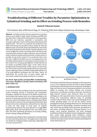
Fig. 1: performancecharacteristicsofhighperformance grindingprocesses Finalshapeandfinishofthepartdependsonthisoperation; soitisaveryimportantprocessinordertomeetstringent specificationsandtolerancesfortheoutputjob.Grindingisa largeanddiverseareaofmanufacturingduetoitsintrinsic ability to produce fine surface finishes and accurate dimensions,cutdifficult tomachinematerials,andachieve high material removal rates. However, there are some challengesaswell,especiallywhenitcomestoopractically. During this experiments different types of grinding variationsobservedbyauthorwassurfacefinishingnotok, ovality, grinding tapper, run out not ok, chatter marks, grindingburnmarks,grindingwheelwearetc.Andobserved possiblecausesforthegrinding variationswasfeed,work rpm,wheelrpm,grindingwheelproperties,grindingforce and power, dressing frequency, dressing amount, no of passes, work material properties, tail stock clamping insufficient,tailstockheadstockcentermisalignment,coolant flow, nozzle angle, grinding wheel unbalance, coolant temperature,coolantfiltration,centerwear,hardnessofthe material,dressingcoolant,dressercondition,grindingdrive motorbelttensionetc.

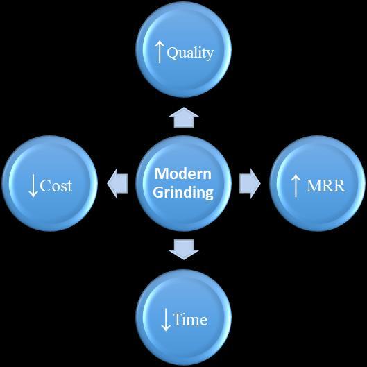
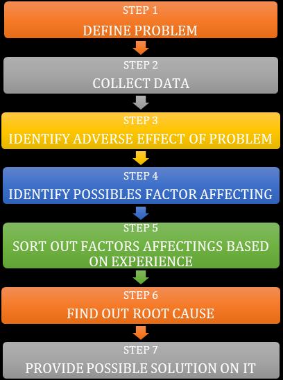
Fig. 3 Tulip Grinding ismostcritical operation in tulipmanufacturing. Becausetherearelotsofcausesofgrindingrejections.The aimofthisresearchistoconcentrateingrindingrejectionby findingitsrootcauses.Andtoavoidchanceofrejection.In that firm author is going to operate micromatic grinding machineformorethansixmonths.Sothisresearchwillbe based on practical experience. Our method to finding out rootcauseisbyusing5why’sandFishboneDiagram.The stepsequencesinmethodologyofthisresearchisshownin fig4below.
Fig. 4 Methodology
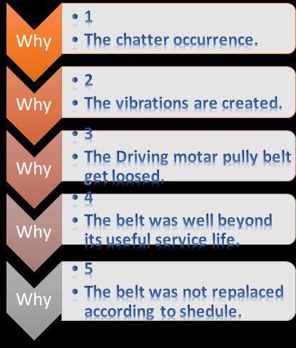
Themajoroperatinginputparametersthatinfluencethe output responses i.e. Metal removal rate and surface roughnessarespeed,feedanddepthofcut.Therehasbeena bit of experimental study, but more extensive research is necessary. Good surface roughness values and high MRR may obtain through process optimization, which needs a deep practical knowledge. The aim of this research is to findingoutrootcausesofgrindingtroublesandproviding possible solution’s on it. So it will reduce time require to findingoutrootcauseofanygrindingtroubleandwhichwill makehelptogrindingoperators.Soultimatelyiswillreduce the machine setup and adjustment time, chance of work rejectionandthentherewillbeimprovementinMRRand surface quality. In this research techniques used for root causesare5whys,Fishbonediagrametc. 1.1 5Why’s It is very simple and effective technique widely used in industries.Inthistechniquewhyquestionisrepeateduntil rootcausenotfindout.Generallywhyisrepeatedupto 5 fivetimes.Becauseit’swellsufficienttofindoutrootcause. EXEMPLE Chatteroccurrenceongrindingsurface. Fig 2 5Why’songrindingchatter.
International Research Journal of Engineering and Technology (IRJET) e ISSN: 2395 0056 Volume: 09 Issue: 01 | Jan 2022 www.irjet.net p ISSN: 2395 0072 © 2022, IRJET | Impact Factor value: 7.529 | ISO 9001:2008 Certified Journal | Page437
2. METHEDOLOGY
Grinding is the important operation because it is the final operations. So there are more chances of rejections. And grinding rejections means rejection in all previous operationsdonebeforegrinding.Sothereishugewasteof money. In the firm where research carried out there was followingoperationsbeforegrinding.1)rolling2)grooving 3)inductionhardening4)magnetictest5)grinding6)crack check.
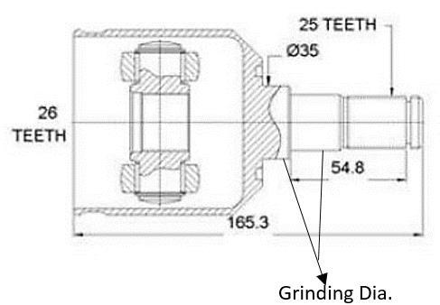
ThisresearchiscarriedoutinfirmGKNDrivelinePune.The main product of that firm is to make CV joints with drive shaft.Inthatfirmtherearedifferentsectioninproduction department namely Inner race, Outer race, Cage, Tripod, Tulip.Thisresearchcarriedoutintulipsection.Becauselots ofrejectionshappened in tulipsection. Tulip isone of the partofCVjoints.
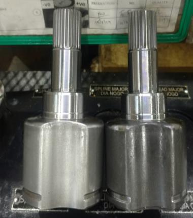
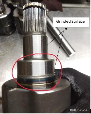
Aluminium Oxide grinding wheel used for experiments. During experimentation wheel rpm is kept around 2000 rpm, work rpm kept between 300 400rpm, Feed 5 15mm/min,Depthofcut0.1 1mm.Waterimmersesoluble oilcoolantused.Thematerialusedfortulipisnotspecific.In thefirmtherearelotsoftypeoftulipaccordingtodifferent customers and theirs different designs. And for each type thereischangeinmaterial.Buttwomostcommonmaterial usedaremildsteelandmediumcarbonsteelwhichareEN24 andAISI1045steel.ThegrindedtulipisshowninbelowFig. 8 Fig.8 TulipafterGrinding
4. FEED
Feed is the one of important parameter which has direct effectonsurfaceroughness.Thefeedofthegrindingwheelis thedistanceofwheelmoveslaterallyacrosstheworkpiece foreachrevolutionincylindricalgrinding. 4.1 Effect of Feed on Roughness (RA)ToanalysestheeffectoffeedrateonRa,theexperimentis carried out practically on micromatic cylindrical grinding machine.Duringexperimentsallparameterskeptconstant. Wheelspeed2000rpm,depthofcut0.1mm,workspeed300 rpmandcoolantflowalsokeptconstant.Thenooffeedused for experiments are 3mm/min, 5mm/min, 8mm/min, 10mm/min,15mm/min.afterexperimentsthevalueofRa for each feed is measure in standard quality lab on roughnesstester.Belowgraphshowsrelationshipbetween Raandfeedwhichweobtained.
Theexperimentsarecarriedoutonmicromaticcylindrical grinding machine in the firm. All experiments are done under supervision of skilled person and production manager.Theworkspecimenistulip.WhichisusedinCV jointsofautomobiles.Fig.5showsthedesignoftulip. Fig 5 Tulip
International Research Journal of Engineering and Technology (IRJET) e ISSN: 2395 0056 Volume: 09 Issue: 01 | Jan 2022 www.irjet.net p ISSN: 2395 0072 © 2022, IRJET | Impact Factor value: 7.529 | ISO 9001:2008 Certified Journal | Page438
3. EXPERIMENT SETUP
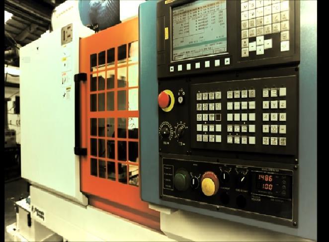
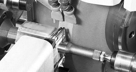
The cnc micromatic machine used for grinding of tulip is showedinFig.6belowandgrindingmechanismoftulipis showedinFig.7below Fig.6 MicromaticGrindingM/C Fig.7 TulipGrindingMechanism
Thedepthofcutisthethicknessoflayerofmetalremovedin one pass of the work w.r.t. the grinding wheel. During experimentswefoundstheimportantofdepthofcutandits effectonwork.
1) The low feed rate produce high finishing surface and reduceMRR,increasecycletime.Sobyusingmultiplestages offeedi.e.roughfeed,supperfeed,andfinefeed.Therequire Racanobtainwithinshortcycletime.
2).toavoidadverseeffect,feedshouldbeproportionaltothe width of wheel face and the finish desired. In general, the narrower the face of the wheel, the slower must be the traversespeed;thewiderthewheelfacethefastercanbethe traversespeed(1)
a) Effects of High Feed
b) Effects of Low Feed
3)Feedratecanbeoptimizeforbestsurfacequalitybyusing TaguchiMethodandResponseSurfaceMethodology(2).
ItcanbeseenfromGraph1thatfeedhasahugeimpacton roughnessvalueRa.Thegraphshowsthat,increaseinFeed results in increase of Ra value and decreasing feed rate improvesurfacefinishing.
2)Excessivefeedcausesthermaldamage,rapidtoolwear.
1) Increase of Ra value because increasing of feed rate, it may lead to increase loads for each abrasive, and higher grindingtemperatureincontactingarea,whichinreturnwill furtheraggravatetheabrasivewear.Thusitresultsinworse machinedsurface
4)Acousticemissionsignalsensorcanbeusedtomonitor thermaldamageduetohighfeed(3)
1)Lawfeedcauseshighcycletimebecauseoflowmaterial removalrate.
d) Solutions to Avoid Adverse Effects of Feed
5. DEPTH OF CUT
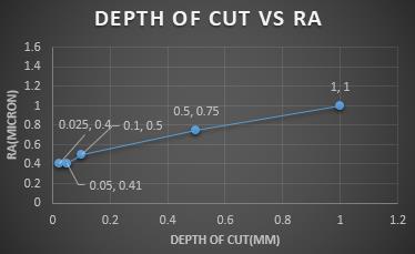
5.1 Effect of Depth of Cut on RaToanalysetheeffectofdepthofcutonRa,theexperimentis carried out practically on micromatic cylindrical grinding machine.Duringexperimentsallparameterskeptconstant. Wheelspeed2000rpm,feedrate3mm/min,workspeed300 rpmandcoolantflowalsokeptconstant. The no of depth of cut used for experiments are 0.025mm,0.05mm,0.1mm,0.5mm,1mm. after experiments thevalueofRaforeachdepthofcutismeasureinstandard quality lab on roughness tester. Below table 1 shows relationshipbetweenRaanddepthofcut. Table -1: RelationshipbetweenRaandDepthofcut. RAinmicron Depthofcutinmm 0.4 0.025 0.41 0.05 0.5 0.1 0.75 0.5 1 1
c) Selection of Feed
International Research Journal of Engineering and Technology (IRJET) e ISSN: 2395 0056 Volume: 09 Issue: 01 | Jan 2022 www.irjet.net p ISSN: 2395 0072 © 2022, IRJET | Impact Factor value: 7.529 | ISO 9001:2008 Certified Journal | Page439 3, 0.6 5, 0.65 8, 0.8 10, 1 15, 1.4 0 0.2 0.4 0.6 0.8 1 1.2 1.4 1.6 0 5 10 15 20 RA(micron) FEED(mm/min) FEED vs RA Chart 1:Feedvs.RA
Alsochart2showstrendlineofdepthofcutvs.RA Chart 2:DepthofCutVSRA
Thefeedamountshouldbeselectas optimum value which will produce required Ra within shortestcycletime.ForthisexperimentsrequirevalueofRa is0.65micron,sotheoptimumvalueoffeedisselectedas 5mm/min.
5)Alsopowersensor,forcesensorcanbeusedforimprove feedperformance(4).



&
d) Solutions to Avoid Adverse Effect of Feed
3.WhenDepthofcutisincreasedthengritsbecomedull.The dullgritsledtoraisedgrindingforceandeffectthegeometry ofworksurface.Suchconditionspresentexcessiveheatingof surface,burnmarksandmaybesmallcracks(6)
As material removal rate is (MRR) is expressed by the multiplicationofcuttingvelocity,feedrateanddepthofcut. Sodecreasingindepthofcutdecreasematerialremovalrate (MRR).Whenmaterialremovalratedecreasethemachining timeincreaseandhencetheproductivitydecreasesolarge depth of cut should be used when higher productivity is required
1. As the depth of cut increases, tool wear increases. An optimum value of depth of cut is recommended for work piecemadeofhardandbrittlematerials.Ifhighervalueof depthofcutwillbeused,thecuttingtoolmaybreak
b) Adverse Effect of Low Depth of Cut
a) Adverse Effects of High Depth of Cut
c) Selection of Depth of Cut
Thedepthofcutamountshouldbeselectasoptimumvalue whichwillproducerequiredRawithinshortestcycletime. ForthisexperimentsrequirevalueofRais0.65micron,so theoptimumvalueofdepthofcutisselectedas0.1mm
[]SEC []SEC 100 20 30 40 50 60 Stepped feed & DOC. Single feed & DOC STEPPED VS SINGLE Chart 3
6. EFFECT OF WORK AND WHEEL RPM
It can be seen from chart 2 that feed has an impact on roughnessvalueRa.Thegraphshowsthat,increaseindepth ofcutresultsinincreaseofRavalueanddecreasingdepthof cutimprovesurfacefinishing.
2. Cutting force is dependent on chip which is itself proportionaltodepthofcut.Hencelargerdepthofcutcan increase cutting force which can hamper machining performancebyinducingvibration(5)
Table 2: SteppedFeedandSteepedDepthofcut SteppedFeed SteepedDepthofcut roughfeed (15mm/min) 1mm superfeed (5mm/min) 0.5mm finefeed (1mm/min) 0.020
Asthedepthofcutincreases,Roughnessvalueincreasedand MRRalsoincreaseslinearly.ForminimumRavaluedepthof cutneedtokeepatlowersidewhileformaximumMRRits value depth of cut need to be at higher side. So it’s make difficulttoselectdepthofcut.Asweselecteddepthofcutas 0.1mmwithfeed3mm/min.soforthisfeedanddepthofcut we got cycle time 56 sec per part. So definitely there was need to reduce cycle time. That’s why we used feed and depthofcutinsteps.Andwereducedcycletimefrom56sec to 30 sec per part. So we improve our production rate by huge amount. The stepped feed and depth of cut we used givenintable2. mm :SteppedVSSinglefeed DOC
International Research Journal of Engineering and Technology (IRJET) e ISSN: 2395 0056 Volume: 09 Issue: 01 | Jan 2022 www.irjet.net p ISSN: 2395 0072 © 2022, IRJET | Impact Factor value: 7.529 | ISO 9001:2008 Certified Journal | Page440
Thetypeofcoolantweusedforallexperimentsinthefirmis water soluble oil immersed. The coolant flow helps to removeawayworkschipsalsoithelpstoexplorenewwork surfacetogrindingwheel.Anothermainpurposeofcoolant flowinwetgrindingistomaintaintemperatureofgrinding zone to avoid grinding burn. The lack of coolant flow has directeffectonsurfaceroughness.Socoolantflowshouldbe maximum.HemantS.Yadav,Dr.R.K.Shrivastavaconclude that increasing coolant flow increase MRR But too much excessive coolant flow increase the grinding force require anddecreaseMRR(10)
7. EFFECT OF COOLANT FLOW-
4.Largedepthofcutwillalsoleadtolesscuttingandmore rubbingorploughingduetomorewear,abnormalfracture andcompletelybreak offofwheelgrains.Thusanoptimum valueneedstobedetermineddependinguponmaterialand machineprocess(7)
Duringexperimentsauthornoticesomeeffectsafterchanges in speed i.e. rpm of wheel and work. When we kept low speed (150rpm) of work we observe increase in RA. And whenweincreasespeedofworkto350rpm,RAgetreduced. Soweincreaseworkspeedagainto450rpm.ItreduceRAby small amount but simultaneously it induce vibration in machine. So we kept the work speed between 250 to 350 rpm.Samethingsweobservewithwheelrpm,i.e.reducing speedincreaseRAandincreasingspeedincreasevibrations. Sowekeptitas2000rpm.Astheworkpiecespeedincreases, therubbingoftheabrasivegrainalsoincreasedsotheMRR also increased. Also for reduce grinding wheel wear it is musttooperatewithoptimumwheelspeed(8).Alsodueto veryhighworkspeedthereischancesofchatterformation (9). And also excessive wheel speed increase chances of wheelexploding(1)



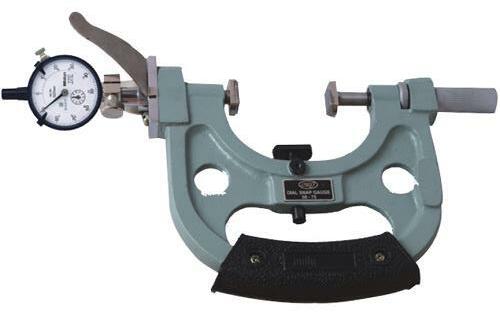
Fig 12 Ovalitysnapgauge
Foamingistheoneofmostcommonproblemincncgrinding. But it is important because during experiments author observe one interesting effect of foaming on grinding operation.
7.1 Presence of Filter Paper
7.2 Effect of Foaming In Coolant
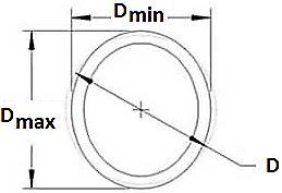
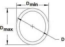
8. OVALITYOvality is the major problem which we faced during experimentation.Ourlotsofrejectsduetoveryhighovality. Ovalityisnothingbuttendencytoproducingtwodiameters majorandminorinsteadofcircularshapeasshowninfig11 below.Weusedsnapgaugetomeasureovalityinthefirmas shown picture 12 below. Our tolerance for ovality was maximum30micron.Ovalitycangiveby=Dmax Dmin Fig11 Ovality
International Research Journal of Engineering and Technology (IRJET) e ISSN: 2395 0056 Volume: 09 Issue: 01 | Jan 2022 www.irjet.net p ISSN: 2395 0072 © 2022, IRJET | Impact Factor value: 7.529 | ISO 9001:2008 Certified Journal | Page441
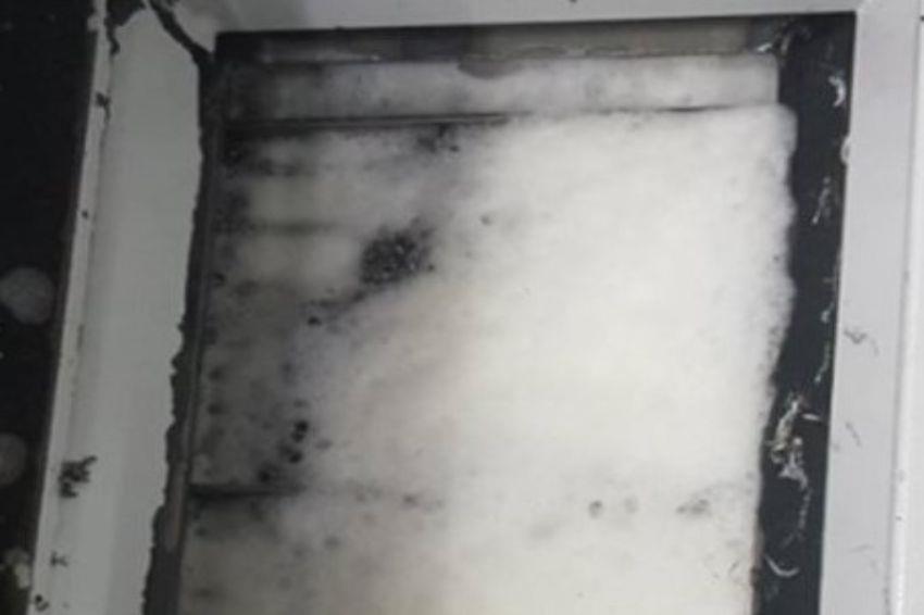
Due to Excessive forming instead of circular the ovality shape of grinding diameter produced. So it increase the chanceofworkrejectionasshowninfig10below. Fig 10. Ovalityshapeofwork When foaming increase then no. of air bubbles creates betweencontactofworkandgrindingwheelandthebubbles createsgapbetweenworkandgrindingwheel.Sothat’swhy unevencontactofworkandwheelhappensduringgrinding which produce oval shape of grinding diameter. The foaming of coolant happens when PH concentration of coolantchange.Ifwaterincoolantbecometoosoftthenit increasefoaming.Soadddefoamers’oilincoolanttoavoid foaming. The operator should have to check PH level of coolantdailytoavoidfoaming.
8.1 Ovality due Insufficient Teal Stock Clamping Force
Thepresenceofcleanfilterpaperisimportantingrinding.It meansitisnecessarytochangefilterpapertimetotime.We observe that if filter paper not changed then wear out grindingwheelparticlesandworkchipsflowbackagainin grindingzonewhichmakesdottedmarksongrindedsurface ofthework whichcanseeeasily.SoitsincreasetheRA of work surface. So the presence of filter paper is not only importantbutthepresenceofcleanfilterpaperisimportant. So operator have to change coolant filter paper as per schedule.
This is one unpredictable reason which we found during experiment.Incylindricalgrindingheadstockisfixedonly tailstock moves to hold work piece and it is done by hydraulicpressure.Duetoinsufficientclampingforcepart producedwithverylargeovalityupto100micronsoparts get directly rejected. Due insufficient hydraulic oil in
Fig 9 Foamingofcoolant
Ovality Measuring Dial Snap Gauge
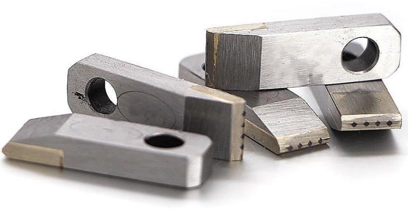
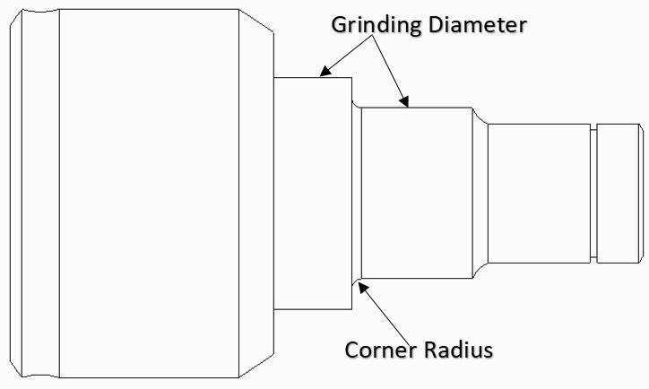
The diamond point of dresser is only important. When it wear out then it not produce require shape profile on grinding wheel so when grinding is done on work then it formstepincorner,taperonsurface, cornerradiusofwrong dimensionalsoafterdressingwegothighsurfaceroughness.
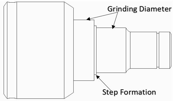
Dressertipmayalsobreakoutduetohighcrossfeedcutand duetomaterialdefect.Belowfigshowsthestepformationat cornerduetowearoutandbrokendresser.
Chart 4 NewDresserVSBrokenDresser
Fig. 13 Dresser
Fig. 14 Stepformation
SURFACE Dressingisthemethodofreshapingtocuttingtool.Andalso itusedtorestoreoriginal shapeofgrindingwheel profile. Duringpracticalexperimentationweobservesomeeffectof dressing.Dressingplayimportantroleingrinding.Weused multi point diamond dresser shown in picture below. We used dressing frequency of grinding wheel after every 20 experiments.
8.2) Ovality Due To Foaming In CoolantThisreasonwealreadydiscussedabove.Thisisalsooneof theunpredictablereasonofovality.WhenPHconcentration of coolant disturb then there is foaming in coolant which creates bubble unbreakable and uneven air gap between contactpointofwheel and work.Andthis unevencontact leadtoovality.
Worndresserproducecornerradiuseitheroverdimension oreitherunderdimension,showninfigbelow Fig 15. Cornerradius Weobservethatthewornandbreakoutdresserproduceline marks on grinding wheel which produce rough surface of work.WemeasuredtheRavalueafterdressingbywornout dresserandnewdresserinqualitylabandweobservehuge difference.Showedingraphbelow 0.7 1.2 0 0.5 1.51 new dresser broken dresser Dressr condition vs RA(micron) dressr condition vs RA(micron)
A) Effect of Dresser Condition
International Research Journal of Engineering and Technology (IRJET) e ISSN: 2395 0056 Volume: 09 Issue: 01 | Jan 2022 www.irjet.net p ISSN: 2395 0072 © 2022, IRJET | Impact Factor value: 7.529 | ISO 9001:2008 Certified Journal | Page442
hydraulic system or due to blockage of oil filter tail stock clampingforcedgetreduces.Alsothereisflowcontrolvalve to adjust hydraulic pressure so we can adjust tail stock clamping force. It is operator responsibility to check hydraulicpressurebeforestartworkingtoavoidrejections.
9 EFFECT OF DRESSING PARAMETERS ON GRINDING
c)Makesurepresenceofdressingcoolantflowduringthe dressingatrightangelordirection
International Research Journal of Engineering and Technology (IRJET) e ISSN: 2395 0056 Volume: 09 Issue: 01 | Jan 2022 www.irjet.net p ISSN: 2395 0072 © 2022, IRJET | Impact Factor value: 7.529 | ISO 9001:2008 Certified Journal | Page443
d)Checkdresserconditioninbetweencyclesifitbrakeout thenreplaceit.
10. ROUNDNESS
a)Optimizedressingparametersbypracticallytrials
b) Set the frequency for dresser change and change the dresseratthatfrequency
B) Effect of Dressing Coolant
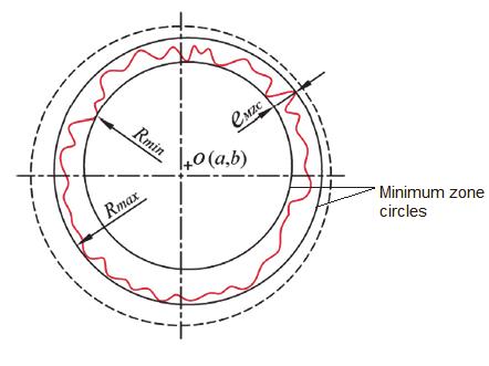
Out of roundness is the critical parameter to control. It is verydifficulttofindoutexactrootcauseofroundnesserror bypracticalexperimentation.Out of roundnessisofgreat importance in case of shafts, axles, pistons, piston pins, crankshafts, roller bearings as out of roundness in these components can lead to excessive noise, vibrations, componentfailure,etc.sothereisneedtooptimizetheinput parameterstohaveminimumoutofroundnesserror.Inthe firmweusedtwodifferentmethodstomeasureroundness whichareCheckingroundnessbydialindicatorbyusingv blockisoneofsimplestmethodusedbyoperator.Andfor more accuracy we used CMM machine for roundness measurement.Roundnessisnothingbutwavinessprofileof workOD. Belowfig16showsprofileofroundness Fig. 16 Roundness
In cylindrical wet grinding, the dressing coolant also importantbecauseweobserveitsdirecteffectondresserlife andsurfaceroughness.Duringthedressingoperatorhaveto checkdressingcoolantflowanditsdirection.Itsdirection should be toward the diamond point of dresser. Lack of dressing coolant reduce dresser life as well as it increase surfaceRA.
During machining we observe that the ratio of wheel and workspeedplayimportantroletocontrolroundness.When weincreasewheelspeedfrom2100rpmto2500rpmthen we observe increase in roundness error to 7 micron. A.A. Ibrahim conclude in their research is that when the work and wheel speed ratio is an integer value then roundness errorincreases(12).Alsoweobservethatwhendepthofcut is high then it lead to increase in roundness error. Better solutionwhichwefoundouttoavoidroundnesserroristhat spark out period or dwell time for 1 to 2 sec after fine grinding. I.e. grinding wheel will remain steady at final position for dwell time. Another one reason of out of roundness is vibration. As we know increase in vibration increase chances of chatter marks but it also effect on roundnessofworkpiece.Increaseinvibrationalsoincrease roundness.A.A.Ibrahimconcludethattheinitialwavinesson theworkpiececontourexcitesthewheel worksystemand theforcedvibrationexistsbetweenthewheelandworkpiece whichincreaseroundnesserror(12).TaranvirSingh,Parlad Kumar,KhushdeepGoyalconcludethatincreaseingrainsize ofwheelincreaseroundnesserror(13) AccordingtoMinke(1999),thehighfrictionlevelsgenerated during the grinding process may be considered as an extremely important factor, which contributes to the roundness errors formation. The employment of cutting fluidswithhigherfrictionreductioncapacityisimportantfor roundnessreduction(14).Therearetwomethodswhichcan be used for roundness optimizations. Artificial intelligent (AI)techniqueforimprovementofroundnesserrorusedby A.A.Ibrahimintheirresearchandoptimizationsofvarious parametersforroundnessbytaguchimethod(15). 10.1) Run out itisoneofthedifficultparametertocontrol. Runoutisnothingbutrotationofworkpieceaboutanaxis away from its centroid axis. It is non desirable characteristics. Increase in run out increase vibration of revolvingpartsandpartmayfailduetofluctuatingload.Out
We studied no of dressing parameters during experimentationswhichdressingfeed,dressingdepthofcut, dressingangle,dressingfrequencyandnoofpasses.Among them dressing feed and depth of cut has more impact. Optimumrangeofdressingparameterscangivethehigher grindingefficiency.Aslowfeedandsmalldepthofcutgives thewheelafinefinish,butifthefeedistooslow,thewheel mayglaze.Afastfeedandhighdressingdepthofcutmakes thewheelfreecutting,butifthefeedanddepthofcutistoo high, the dresser will leave tool marks on the wheel also thereischancesofdresserbrake.Thecorrectfeedanddepth ofcutcanonlybefoundbytrial,butauniformrateoffeed anddepthofcutshouldbemaintainedduringanyonepass. Dressing time is non productive so dressing frequency is should high as possible. The surface roughness increases withincreaseindragandangleofthedresser,anddecreases withincreaseinnumberofpasses(11)
C) Effect of Dressing Parameters
D) Solutions to Avoid Adverse Effects of Dressers-
11. CHATTER MARKS
Fig. 17 Chattermarks
2. Reducing wheel and work rpm increase roughness and increasingRpmspeedincreasevibrations.Alsoduetovery
Whencentertipwearoutthenworkpiecedoesnotrevolve atanidleaxisduringmachiningandrunoutincreases.Soby controlling ovality, roundness, tailstock and headstock centermisalignmentandreplacingtailstockwearoutcenter wecancontroltherunout.
The chatter occur due to vibration in machine. Due to vibration there is uniforms contact of grinding wheel and work. So to prevent chatter occurrence it is necessary to reduce vibration magnitude in machine. The chatter phenomenonalsoreducegrindingwheellife.Thevibration may force excited or self excited. The root cause of Self excited vibration are generally critical to detect. After experiments we found out some main reasons of chatter a)occurrence.Ifdepthofcutistooheavythenitincreasethechanceof chattermarks.Veryhighdepthofcutandhighfeedincrease theloadoncuttingwheelwhichcreatebouncingeffectcause chatteronworksurface
Fig 18. Pulley
Prof.DilipKhedkarandVinodHangefoundoutvariousroot causes for chatter formation in their research paper also theysuggestedcorrectiveactiontoavoidchatter(17).
Mate Toth, Neil D Sims, David Curtis conclude that chatter formationoccursdueunevenwearofgrindingwheeland unevenwearofgrindingwheelcanquantifiedbyanuneven specificenergydistributionaroundthecircumferenceofthe grindingwheel(18)
d) Another and most important root cause of chatter is wheeloutofbalance.Whenwheelbalancingisnotokthen definitelytherewillbechatterformation.Wheelmaybeout of balance due to dressing by worn out dresser or due to when there will be cracks in wheel and material removed out. Generally wheel is balanced while installing. Another onewaytobalancewheelisautobalancing.
International Research Journal of Engineering and Technology (IRJET) e ISSN: 2395 0056 Volume: 09 Issue: 01 | Jan 2022 www.irjet.net p ISSN: 2395 0072 © 2022, IRJET | Impact Factor value: 7.529 | ISO 9001:2008 Certified Journal | Page444
1. High feed and high depth of cut increase surface roughness and tool wear also low feed and depth of cut reduce material removal rate so we can maintain both roughnessaswellasMRRbyusingsteepedfeedanddepthof cut.Alsowecanuse differenttechniques to optimize feed and depth of cut like Taguchi method, Response surface methodology,Acousticemissionsignalanalysis,bytrialand errormethod.
ofroundnessaswellasovalityarethecausesofrunout.Also we observe that head stock and tail stock center miss alignment that is not in co axial is the major reason for increaseinrunout.Oneofmajorreasonwhichweobserve duringpracticalexperimentsisthetailstockcentertipwear.
c)Anotheronecauseofchatterisveryhighworkspeedof rotation. So it is necessary to maintain work speed in optimumrange.Whenwekeptourworkspeedas450rpm then we observe chatter formation on work. So again we reduceworkspeedto350rpm.Theworkspeedhasdirect effect on arc of contact with grinding wheel. And the optimumworkrpmvariesfrommachinetomachineandwe canonlyfindoutitbypracticalexperiments.
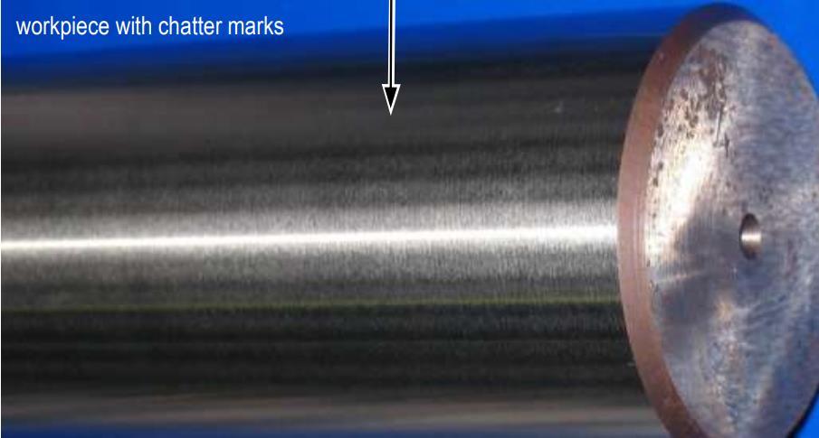
Aftersurfaceroughness(RA)chatteringrindingisthemost commonandcriticalcauseobserveincylindricalgrinding. During experiments our lots of part get rejected due to chatter marks on grinding surface. Below picture shows chatter marks on grinding surface. The chatter marks can easilydetectsbyvisualinspection.
Felipe Aparecido Alexandre and Wenderson Nascimento Lopes conclude in their research paper is that chatter formationcanbemonitorsbydigitalsignalprocessing(16).
12. CONCLUSIONS Inthispaperwediscusseddifferentkindofproblemoccurs incylindricalgrindingandwefoundoutrootcausesforthat. Fromthatfollowingconclusionsareconcluded.
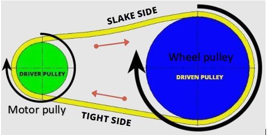
b)Anothermaincauseweobservewhichisbeltcondition. Thebeltwhichisconnectedtodrivingpulleyofmotorand drivenpulleyofgrindingwheelasshowninfigbelow.When belttensionreducethenduringrotationatparticularrpm belt oscillate which create vibration on grinding wheel so chatteroccur.
International Research Journal of Engineering and Technology (IRJET) e ISSN: 2395 0056 Volume: 09 Issue: 01 | Jan 2022 www.irjet.net p ISSN: 2395 0072 © 2022, IRJET | Impact Factor value: 7.529 | ISO 9001:2008 Certified Journal | Page445 highworkspeedthereischancesofchatterformation.And also excessive wheel speed increase chances of wheel 3.exploding.Increasing coolant flow increase MRR But too much excessive coolant flow increase the grinding force require and decrease MRR. Foaming of coolant increase ovality of work piece. Coolant foaming increase when PH concentrationnotok. 4.Whentailstockhydraulicclampingpressureisinsufficient thenitincreaseworkovalityandincreaseinovalityincrease runout. 5. Worn dresser produce line marks on grinding wheel whichproduceroughsurfaceofwork.Highdressingdepthof cutandlackofdressingcoolantincreasesurfaceroughness. 6. Increase in wheel rpm and depth of cut increase roundnessofwork.Alsohighvibrationincreaseroundness. 7. Tailstock and head stock center axis miss alignment increaserunout.Alsotailstockcentertipwearincreaserun 8.out.Reduction in pulley belt tension, high work and wheel rpm, out of wheel balancing introduce vibration result in chatterformationongrindingsurface. From above conclusions we can take quick and right correctiveactiontoavoidgrindingtrouble. REFERENCES [1] S.J.Patel,(AmrutEngineeringPvtLtd,India)“Analysisof Grinding Wheel”, International Conference on Clinical MicrobiologyandImmunology,2019|Volume3Issue4 [2] M. Aravind and Dr. S. Periyasamy, “Optimization of Surface Grinding Process Parameters By Taguchi Method And Response Surface Methodology”, International Journal of Engineering Research & Technology (IJERT), ISSN: 2278 0181¸ Vol. 3 Issue 5, May 2014 [3] Xun Chen & Tahsin T. Öpöz, “Effect of Different ParametersonGrindingEfficiencyAndItsMonitoring By Acoustic Emission”, Production & Manufacturing research,2016Vol.4,no.1,190 208 [4] W. Brian Rowe, “High Productivity in Precision Grinding”, Inventions 2018, 3, 24; doi:10.3390/inventions3020024 [5] S. Jeevanantham1*, N.M. Sivaram2, D.S. Robinson Smart3,S.Nallusamy4,N.ManikandaPrabu5,“Effectof MachiningParametersonMRRandSurfaceRoughness in Internal Grinding using EN8, EN31 Steel”, InternationalJournalofAppliedEngineeringResearch ISSN 0973 4562 Volume 12, Number 11 (2017) pp. 2963 2968 [6] S. M. Deshmukh1, R. D. Shelke2 and C. V. Bhusare3,” OptimizationofCylindricalGrindingProcessParameters of Hardened Material using Response Surface Methodology”, IJISET International Journal of Innovative Science, Engineering & Technology, Vol. 3 Issue11,November2016 ISSN(Online)2348 7968| ImpactFactor(2015) 4.332 [7] Amandeep Singh Padda*, Satish Kumar**, Aishna Mahajan***M.Tech,”EffectofVaryingSurfaceGrinding ParametersontheSurfaceRoughnessofStainlessSteel”, International Journal of Engineering Research and General Science Volume 3, Issue 6, November December,2015 ISSN2091 2730 [8] Amandeep Singh Bains1, Jagjeet Singh2 & Rupinder Singh3,” Effect of Cutting Parameters on Cylindrical Grinding of Aisi H11 Steel Under Dry Conditions”, International Journal of Latest Trends in Engineering andTechnology SpecialIssueAFTMME 2017,pp.106 109 e ISSN:2278 621X [9] JPraveenKumar1*,BIndhirajith1andKThiruppathi1,” Quality Improvement of A Grinding Operation Using Process Capability Studies”, ISSN 2278 0149 www.ijmerr.com Vol. 1, No. 1, April 2012 © 2012 IJMERR. [10] HemantS.Yadav,Dr.R.K.Shrivastava,”EffectofProcess Parameters on Surface Roughness and MRR in Cylindrical GrindingusingResponse SurfaceMethod”, International Journal of Engineering Research & Technology (IJERT)ISSN: 2278 0181 Vol. 3 Issue 3, March 2014 [11] Dadaso D. Mohite1, S.M. Jadhav2,” An Investigation of Effect of Dressing Parameters for Minimum Surface Roughness using CNC Cylindrical Grinding Machine” IJREAS VOLUME 6, ISSUE 6 (June, 2016) (ISSN 2249 3905)InternationalJournalofResearchinEngineering andAppliedSciences. [12] A.A. Ibrahim,” Improving Roundness Error In The Cylindrical Plunge Grinding Using Ai Technique”, Engineering Research Journal 117(June2008) M 124 M139 [13] Taranvir Singh, Parlad Kumar, Khushdeep Goyal*,” OptimizationofProcessParametersforMinimumOut of Roundness of Cylindrical Grinding of Heat Treated AISI 4140 Steel”, American Journal of Mechanical Engineering,2014,Vol.2,No.2,34 40Availableonline athttp://pubs.sciepub.com/ajme/2/2/1©Scienceand EducationPublishingDOI:10.12691/ajme 2 2 1 [14] Minke, E. “Contribution to the Role of Coolants on GrindingProcessandWorkResults”.3rdInternational Machining&GrindingConference,October4 7of1999, WestinHotel,Cincinnati,Ohio. [15] Rajasekaran Rekhaa, Neelakandan Baskara, MallasamudramRamanathanAnanthaPadmanabana& Angappan Palanisamyb,” Optimization of cylindrical grinding process parameters using meta heuristic algorithms”,IndianJournalofEngineering&Materials SciencesVol.27,April2020,pp.389 395 [16] FelipeAparecidoAlexandre1,*,WendersonNascimento Lopes 1, Fábio Isaac Ferreira 1, Fábio R. L. Dotto 1, PauloRobertodeAguiar1andEduardoCarlosBianchi
International Research Journal of Engineering and Technology (IRJET) e ISSN: 2395 0056 Volume: 09 Issue: 01 | Jan 2022 www.irjet.net p ISSN: 2395 0072 © 2022, IRJET | Impact Factor value: 7.529 | ISO 9001:2008 Certified Journal | Page446 2,”ChatterVibrationMonitoringintheSurfaceGrinding rocessthroughDigitalSignalProcessingofAcceleration Signal”,Proceedings2018,2,126;doi:10.3390/ecsa 4 04927 [17] ofVinodHange,Prof.DilipKhedekar,”RootCauseAnalysisGenerationofChatterinCrankShaftPinGrinding”, International Journal of Latest Trends in Engineering andTechnology,ISSN:2278 621X,Vol.7,Issue1May 2016 [18] Mate Toth,Neil D. Sims, David Curtis, ”An Analytical Study of Wheel Regeneration in Surface Grinding”, ScienceDirect,ProcediaCIRP82(2019)214 219 BIOGRAPHY Santosh TukaramAyanar Hehas completeddiplomainMechanical from MGM POLY. Aurangabad & his BE from Dr. Vitthalrao Vikhe Patil College of Engineering, Ahmednagar.Hehaspublishedone research paper on die design and He has one year industrial experience in production department.Nowheisworkingas designengineer.