
:
International Research Journal of Engineering and Technology (IRJET) e ISSN: 2395 0056 Volume: 09 Issue: 01 | Jan 2022 www.irjet.net p ISSN: 2395 0072 © 2022, IRJET | Impact Factor value: 7.529 | ISO 9001:2008 Certified Journal | Page851 Electric Vehicle Mohamed Salman M1, Divakkar VP2 , Koushik Sekar3 , Rahul L4, Srivathsan K5 , Mufaddal Attarwala6 *** Abstract Thegoalofthisproductdesignrecordistocreate all the documentation had to construct the prototype. Through iterative evaluation and optimization, the layout has been superior from beyond design reports. The prototypehasbeendesignedtoensurethatitcomplieswith standardsandissecuretoexperienceonIndianroads 1.INTRODUCTION
Eachparameterimpactstheperformanceandmanaging ofthebikeotherwiseasaconsequencetheremaybenotop ratedpriceforeachparameter.Thesortofgeometryrequired relies upon at the characteristics anticipated from the motorbike.
Thecasterperspectivevariesinkeepingwiththeformof bike:from19°(speedway)to21 24°forcompetitionorsport motorcycles,upto27 34°forjourneyingmotorcycles.Froma structural factor of view, a completely small perspective reasonsincrediblestrainattheforkallthroughbraking.Since thethefrontforkisalternativelydeformable,eachflexionally andtorsionally,smallvaluesoftheperspectivewillresultin more strain and therefore extra deformations, that could motive dangerous vibrations inside the front meeting (oscillation of the front meeting around the axis of the steeringhead,referredtoaswobble).Thefeeofthecaster angle is carefully associated with the price of the trail. In fashionable,withapurposetohaveanawesomefeelingfor themotorbike’smaneuverability,angrowthinsidethecaster anglemustbecoupledwithacorrespondingincreaseinthe trail.Thecostofthetraildependsatthesortofmotorcycle anditswheelbase.Itrangesfromvaluesof75toninetymm in competition motorcycles to values of 90 to 100 mm in travellingandsportmotorcycles,uptovaluesof120mmand pastinmerelyvisitingmotorcycles. 1.2 Trail Ifthecostofthetrailhavebeenpoor(thecontactpointin frontoftheintersectionpointofthesteerageheadaxiswith theroadaircraft)andthinkingaboutthatfrictionforceFis continuallyinsidethecontrarypathofthespeedofslippage, amomentacrosstheguidanceheadaxisthatcouldtendto growththerotationtotheleftwouldbegenerated.Onecan take a look at how friction force F would amplify the disturbing effect, severely compromising the motorcycle’s equilibrium.Theavenueprofilecanmakethetrailbad,asan instance,whilstthewheelgoesoverasteporbump.Thisis thecausewhyweavoidhavingaterriblepathprice.Sincethe loadatthefrontwheelsishighbecauseoftheburdenofthe motorcycle,thechoiceofasmallpathlowersthepriceofthe torque that the rider ought to apply to the handlebars to executeagivenmaneuver.Inaddition,it'smileswellworth pointing out that these bikes are commonly used at as an alternative low velocities, and that they do now not consequentlywantlengthytrails,which,asformerlynoted, assuresaexcessivedirectionalstabilityathighvelocities.The cost of the path depends onthe form ofmotorbike andits
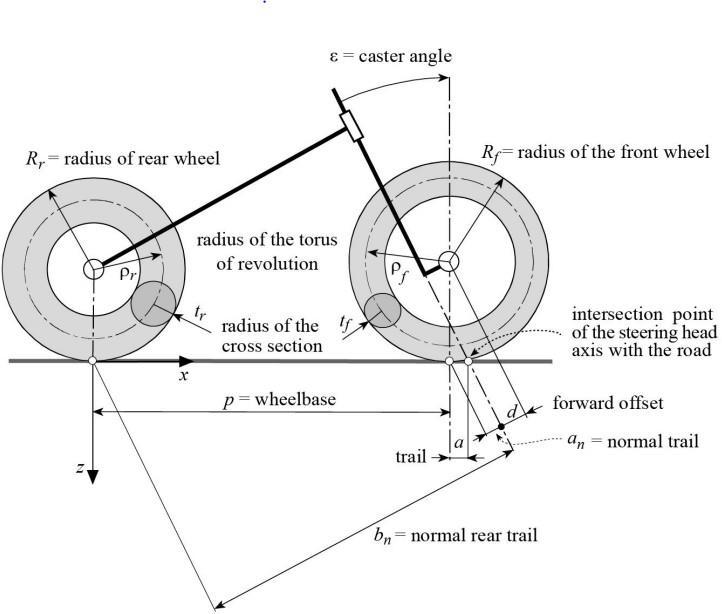
The most important part of motorbike designing is figuringoutthegeometryofthechassis.Itoutcomesinthe usual behavior of the bike. The geometry determines the general stiffness, aerodynamics, rider position and luxury, and also impacts dealing with, manoeuvrability and responsiveness.Theparametersthatonthewholedictatethe geometryconsistof: Theparametersthatprimarilyaffectthegeometryinclude Castorangle(Rakeangle) SteeringWheelbaseTrailOffset These parameters give the foundation to our motorcycle bygeometry.Theinterdependenceoftheseparametersaregiventhefollowingequations: a=an/cosε Where ‘a’ is the ground trail , ‘ε’ representstherakeorcastorangleand‘an’is thenormaltrail
1.
2. bn=(p+a) cosε Where‘bn ’istherearnormaltrailand‘p’ isthe wheelbase 3. an=Rf sinε d Where‘Rf’isthefrontwheelradiusand‘d’ isthe steeringoffset.
1.1 Castor angle

International Research Journal of Engineering and Technology (IRJET) e ISSN: 2395 0056 Volume: 09 Issue: 01 | Jan 2022 www.irjet.net p ISSN: 2395 0072 © 2022, IRJET | Impact Factor value: 7.529 | ISO 9001:2008 Certified Journal | Page852 wheelbase.Itlevelsfromvaluesofseventyfivetoninetymm inoppositionbikestovaluesofninetytoonehundredmmin journeyingandsportmotorcycles,uptovaluesof120mm andpastininbasictermsjourneyingmotorcycles. 2. WheelBase
2. An unfavorable increase in the minimum curvature radius, since it makes it more difficult to turn on a path that has a small curvatureradius,inordertoturn,theremust be an unfavorable increase in the torque appliedtothehandlebars.
Thevalueofthewheelbasevariesaccordingtothetype of motorcycle. It ranges from1200mminthecaseofsmall scooters to 1300 mm for light motorcycles (125 cc displacement) to 1350 mm for medium displacement motorcycles(250cc)upto1600mm,andbeyond,fortouring motorcycleswithgreaterdisplacement.
2.1 Steering Offset
Ingeneral,anincreaseinthewheelbase,assumingthat theotherparametersremainconstant,leadsto:
5. A favorable increase in the directional stabilityofthemotorcycle.
1. Anunfavorableincreaseintheflexuraland torsionaldeform abilityoftheframe.These parameters are very important for maneuverability (frames that are more deformable make the motorcycle less maneuverable).
4. A favorable reduction in the pitching movementgeneratedbyroadunevenness
The steering offset is the measurement of the lateral deviation,fromthemiddleofthetyrecontactsurface,tothe tracepoint.Offsetofthewheelspindlefromthesteeringaxis is measured at right angles to that axis. With a negative steeringoffset,(seefigure)thetrackpointliesoutsideofthe center,andwithpositive,inside.Ifthetracepointliesdead center,itsvalueiszero.Considering the effects of above parameters we conducted multiple iterations to arrive at theidealvehiclegeometryfororprototype In the rear suspension the squat ratio ‘R’ is an important parametertoconsiderasitdecideshowtherearsuspension reactstothedifferentmomentsgenerated,bothstaticand dynamicWedefinethesquatratioRastheratiobetweenthe moment generated by the load transfer and the moment generated by the sum of the chain force and the driving force:
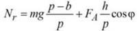
R=(h*cosΦ)/(p[sinΦ+Rr*sin(Φ n)/rc Accordingtothesquatratio3instancescanarise:
R=(NtrLcosφ)/(SLsinφ+TLsin(φ n))where Φ=swingarmangleL=swingarmlength S= moment generated by driving force T= moment generatedbychainforceNtr=loadtransfer nisgivenbyn=arcsin[(LsinΦ+yp (rc rp))/Lc) Whereypistheverticalcoordinateofthedrivesprocket shaftrpandrcrepresenttheradiiofthepowersprocketand therearsprocket,brepresentstheverticaldistanceamong theaxesofthesprockets,Lcisthelengthoftheinstantlyline sectionofthechain. Expressingtheweightswitchasafunctionoftheusingforce, the ratio is a characteristic of only the geometric characteristic.
3. A favorable decrease in transferring the load between the two wheelsduringtheaccelerationandbraking phases, with a resulting decrease in the pitchingmotion.
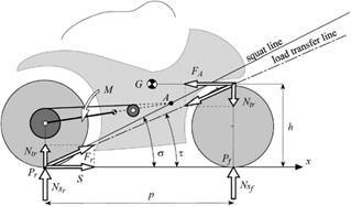
1. PointAliesatthedirectlylineoftheweightswitch, thisisσ=τ;inthisexampleR=1.Duringthethrust phase there are no extra moments working on the swingingarm,so the suspensionspringisnow not careworncomparedwiththestaticsituation.
Steeringisagoverningsubsystemthat'sasetofmechanical linkagestohelptheridertoguidethecarindesiredcourse ortobarteraflipalongroundpathway.Steeringgadgetofa wheelerinvolvescritical parameters which determine the steadinessandmanoeuvrabilityofthevehicle. Aguidance gadget for a motorcycle includes a head pipe, a steerage stem,apinnaclebridge,abacksidebridge,afrontfork,anda steeragehandlebar.
3.PointAliesabovethestraightlineoftheloadtransfer, thatisσ>τ;inthiscaseR<1:Themomentgeneratedbythe resultantforceFrcausestheextensionofthespring.
Steering system
7. Tireproperties(slideslipangles)
Asdynamicanalysiswasnotconductedafactorofsafety of 1.5 2 is favorable as per previous experience to compensateforfatigueandtocompensateforrandomfactors afactorofsafetyofaround2wasconsideredappropriate.
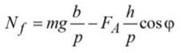
Thefollowingforcesactonamotorcycle: Theweightmgactsatitscenterofgravity. ThedrivingforceT,whichthegroundappliestothe motorcycleatthecontactpointoftherearwheel.
Themotorcyclesteeringmechanismforagivenoffset When turning the handlebars, retaining the motorbike flawlessly vertical, the steerage head lowers and simplest beginstoriseforextremelyexcessivevaluesofthesteering
Where,
Theattitudeverticaldisplacementofthewheelcentre:
1.PointAliesatthedirectlylineoftheweightswitch,thisis σ=τ;inthisexampleR=1.Duringthethrustphasethereare no extra moments working on the swinging arm, so the suspensionspringisnownotcareworncomparedwiththe staticsituation.
International Research Journal of Engineering and Technology (IRJET) e ISSN: 2395 0056 Volume: 09 Issue: 01 | Jan 2022 www.irjet.net p ISSN: 2395 0072 © 2022, IRJET | Impact Factor value: 7.529 | ISO 9001:2008 Certified Journal | Page853
3.PointAliesabovethestraightlineoftheloadtransfer,that is σ>τ ; in this case R<1 :The moment generated by the resultantforceFrcausestheextensionofthespring.
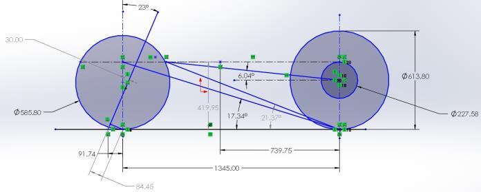
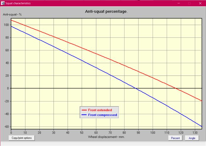
Thesquatratio‘R’canalsobeexpressedasR=tanτ/tanσ
Where,Accordingtothesquatratio3instancescanarise:
1. τ(loadtransferangle)=17.34° 2. σ(squatangle)=21.37° ThereforeR=0.79,andthusR<1,Thishelpstheanti squat natureofthemotorcycle. Detailedstaticloadcases
The motorbike steerage behaviour relies upon on diverse geometricparameters:1.Wheelbase 2.Offsetthree.Rake/castoranglefour.Wheelradii5.Turning 6.perspectiveRollangle
2.PointAliesbeneaththeinstantlylineoftheburdenswitch, thisisσ<τ;inthiscaseR>1:themomentgeneratedviathe consequentforceFrreasonsacompressionofthespringin additiontotheonecreatedbywayofthestaticload.
2. PointAliesbeneaththeinstantlylineoftheburden switch, this is σ<τ ; in this caseR >1 : the moment generated via the consequent force Fr reasons a compression of the spring in addition to the one createdbywayofthestaticload.
Thesquatratio‘R’canalsobeexpressedasR=tanτ/tanσ
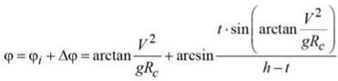
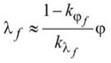
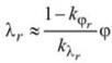
International Research Journal of Engineering and Technology (IRJET) e ISSN: 2395 0056 Volume: 09 Issue: 01 | Jan 2022 www.irjet.net p ISSN: 2395 0072 © 2022, IRJET | Impact Factor value: 7.529 | ISO 9001:2008 Certified Journal | Page854 =.2929(1 SQRT(1 sin^2(22)sin^2(23)) 0.03(sin23(1cos22) =0.002301mm TurningRadius Radius=Wheelbase/Sin(90 Steeringangle) =1.345/sin(90 22)=1.45m WheelFlipFlopfactor: Wheelflipflopfactor=trail*sin(headangle)*cos(headangle) = =32.991.74*sin(67)*cos(67)mmMotorcycleparameterswhileinacurve Themotorcyclewhilegoingaboutasteadyturnissubjected totwoforcesi.ethetiltingeffect(Rolling)andtherestoring moment generated by the Centrifugal force that tends to keep the vehicle in a balanced state i.e prevents it from fallingintothecurve. EffectiveRoll =60.97)/419.95=arctan(23.5^2/9.81*40)+arcsin(55*arctan(23.5^2/9.81*40Angle:55degrees V=forwardvelocityofthemotorcycleΩ=Angularyawrate (yawvelocity) Rc=theradiusoftheturn g= Acceleration due to Gravity (9.81 m/s^2) h= Centre of gravityheight 2t=Tirethickness(120mm)Yawvelocity: Ω=V/(Rc) =23.23/(40) =0.58m/sWhere, V=Forwardvelocity,Rc=RadiusofCurve LateralSlip(slipangle): Itisdefinedastheangleformedbythedirectionofforward motion and the plane of the wheel.When sideslip angles approachzero,steeringiscalledkinematicsteering. We consider neutral steering condition for which we have takenthevaluesofthecamberandcorneringcoefficientsas 0.6and12respectively Neutralsteering:Steeringratiois‘1’i.efrontslip=rearslip Frontslipangle: =(1 =1.01610.8)*60.97/12 RearSlipAngle: =(1 DragAerodynamicwhile=1.01610.8)*60.97/12cornering:Forces:force=(d*V^2*Cx*S)/2 =(1.225*14.38^2*0.5*(0.6x10^ 6))/2 =3.79x10^ 5N

2. d=fwR=4.39mm Where,fw=rollingresistancecoefficient=0.015R=tire’s radius=292.9
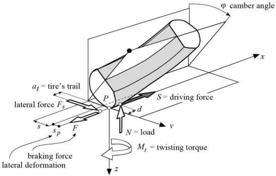
3.Overturningmoment:TheoverturningmomentMxis generated by the vertical load N whose arm is the lateral deformationsp.Mx=−spN=1580Nmm
Theforcesunderconsiderationareasfollows:
Tire ModelSetupofthe
International Research Journal of Engineering and Technology (IRJET) e ISSN: 2395 0056 Volume: 09 Issue: 01 | Jan 2022 www.irjet.net p ISSN: 2395 0072 © 2022, IRJET | Impact Factor value: 7.529 | ISO 9001:2008 Certified Journal | Page855 dWhere:=airdensityV=velocity Cx=Dragcoefficient S=Frontalsurfacearea VerticalLoadontireswhilecornering: Front =543318.08(78*(419.95/1345)cos(60.97)=161*9.81*(739.75/13445)78*(419.95/1345)*cos(60.97)=161*9.81*(739.75/13445)Tire=856.85NRearTire=856.85NLateralForcesonbothtires:Fronttire:=(12*1.0161+12*60.97)*856.85=637353.47NRearTire:=(12*1.0161+12*60.97)*722.55NEffectivesteeringAngle:=Steeringangle+1.01611.0161=22degrees
1. Normalforce:Normalforceisappliedatapointthat precedes, by the distance d, the position of the theoreticalcontactpoint.
5. Yawing moment: Yawing moment includes two contributions.Thefirstterm,duetothelateralforce,tendsto align the plane of the tire in the direction of velocity. The
Themodelofthemotorcycletiretakesintoconsideration theforcesactingonpointsnearthetheoreticalcontactpoint definedbythetire’sgeometry.
tire
4.Rollingresistancemoment:Rollingresistancemoment is generated by the asymmetric distribution of normal stressesthatcausesaforwarddisplacementofverticalload. Thetire’srollingresistancemomentis:My=d*N=4.39*161 *9.81=6933.6Nmm
2.Longitudinalmmforce: The force is applied to a point displacedlaterallyfromthetheoreticalcontactpointbecause ofthetire’slateraldeformability.Thelateraldisplacementsp, depending on the lateral stiffness of the tire, is generally negligible with respect to the geometric displacement s derivingfromtherollinclinationofthewheel.Themoments actingaroundthex,yandz axesaregeneratedbytheforces describedaboveandbythetwistingmoment.

1.
1.
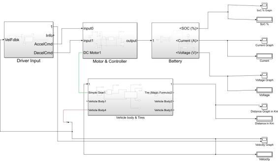
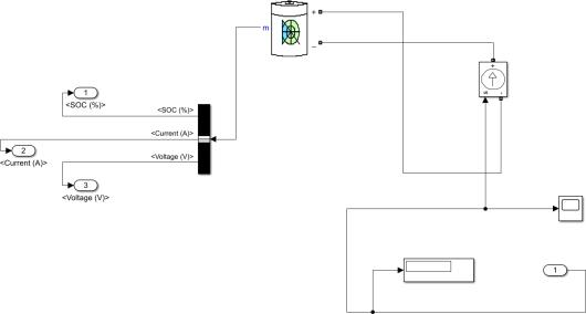
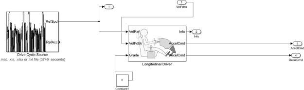
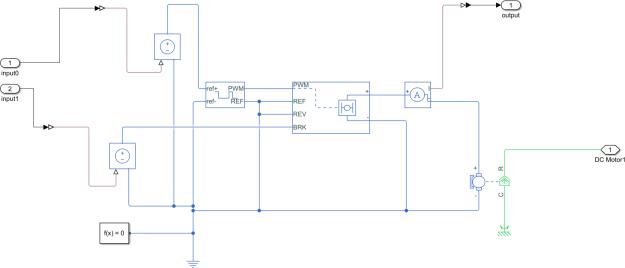
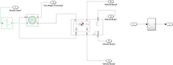
capabilofcellp.C.,calAfterwhichwheelcalculateautomobile.sourceproviding(Federalthedrivearea*draggrossparameters.frontalvehicleforceforce,orderAVehiclemethodology:modelphysicalmodelofthevehiclewascreatedinSimulink.Intocalculatethismultipleresistiveforceslikerollingaerodynamicforce,gradientforceandaccelerationiscalculatedusingcoefficientofrollingfriction,grossmass,inclinationofroadsurface,dragcoefficient,area,densityofairandwheelradiusasinputI.Rollingforce=Coefficientofrollingresistance*9.81*massofvehicleII.Aerodynamicforces=0.5*densityofair*frontalcoefficient*u2WhereuisvehiclevelocityfromcycleIII.Gradientforce=9.81*massofvehicle*sin(theta)WherethetaisinclinationangleofroadsurfaceIV.Accelerationforce=massofvehicle*d2u/dt21.DrivecyclefactsDrivecyclesupplyisfurnishedtothecarmodeltodecideinternetpowerrequiredtosatisfythecycle.FTP75checkprocess)forcecyclefactsbecomeappliedforpowercycleinputtothevehiclemodel.Drivecycleblockconsistsofvelocitytimefactsforthe2.MotorMotorefficiencyandequipmentratiostatisticsisinputtopowerrequiredtoreapfavoredtorquetothereartoconquertheresistivepressureontherearwheeliscalculatedfromtheabovesubsystem.3.Batterypercentcalculatingtheenergyrequirementofthemotorweculatethebatteryability.Totalquantityofcellsinbatteryno.Ofcellsinseriesandparallelcanbecalculatedwithabilityandbatterybackability.SOCiscalculatedtheusebatterymoderndischargedbyusingthemotorandtheityofthebatteryp.C..
International Research Journal of Engineering and Technology (IRJET) e ISSN: 2395 0056 Volume: 09 Issue: 01 | Jan 2022 www.irjet.net p ISSN: 2395 0072 © 2022, IRJET | Impact Factor value: 7.529 | ISO 9001:2008 Certified Journal | Page856
Electrical1.ElectricalSystemvehiclemodel AmodelofthevehiclewascreatedinMatlabSimulinkto analysethevariousparametersrequiredforthebatterypack. Theparametersthatwecalculatedarebatterypackcapacity and SOC for a required range. This is achieved by the following
Itwasdecidedtogowithaoffollowingtireprofiles: Front 110/70R17 2.Rear 130/70R17
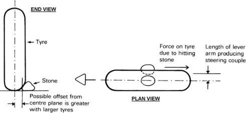
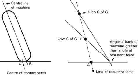
second term increases with the camber angle and works againstalignment. Factorstakenwhiletireselection: Largetiresincreasetheunsprungmasstoo,tothe detriment of roadholding. Larger tires alsoincrease precessionalforces. Road disturbance such as a stone can cause a coupletendingtosteerthewheeltothatside.Awide tire isfoundby morestones andproducesa higher 3.couple.Widetiresmayimpairhandlingandstability,even though grip may be improved. The contact patch movesawayfromthecentreplaneofthewheelorthe steeringaxisasthemachineisbanked.Agreaterangle ofleanisnecessarytobalancecentrifugalforce,and thismayrequireaslightlyhighercentreofgravityto restorecorneringclearance.
Mz=−atFs+Mt
2.
The tiresselectedare Michelin pilot street radial tiresand complywithrequirementsspecifiedinAIS:044(Part1to3): 2004asapplicabletillthecorrespondingBISspecifications arenotifiedundertheBureauofIndianStandardsAct,1863 (63of1986).
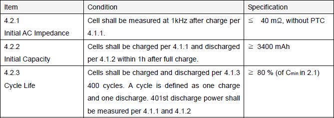
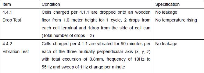
International Research Journal of Engineering and Technology (IRJET) e ISSN: 2395 0056 Volume: 09 Issue: 01 | Jan 2022 www.irjet.net p ISSN: 2395 0072 © 2022, IRJET | Impact Factor value: 7.529 | ISO 9001:2008 Certified Journal | Page857 Fig: Simulink Model Fig: Driver Input Block Fig: Motor and Controller Block Fig: Battery Block Fig: Vehicle Body and Tires Block SOCwasreducedfrom100%to10.5%aftercompleting thedrivecycle. 2. Cell : LG CHEM 18650 MJ1 Here we have chosen lithium ion cells over othercellsduetofollowingreasons: 1. Highenergydensity 2. Lowself discharge 3. Lowmaintenance 4. Many options to choose in terms of capacityandgeometry 5. Flexibility and high power to weight ratio 6. Highlifecycle Incellselectionwehadmanydifferenttypesofcellchemistry and dimensions. So we did athorough research on which chemistry to choose among Lithium Ion cells. The below tablegivesthespecificationofthechosencell. 1.2.StandardDischarge: “Standard Discharge” shall consist of discharging at a constant current of 0.2C to 2.50V. Discharging is to be performedat23ºC±2ºCunlessotherwisenoted(suchas capacityversustemperature).
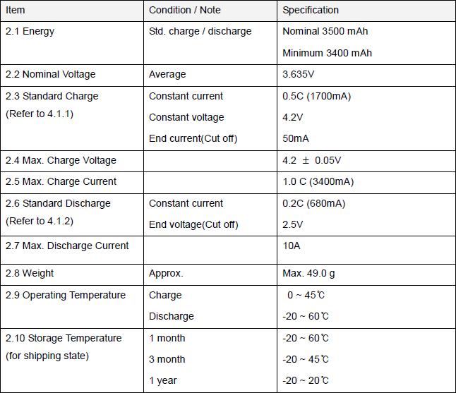
The drove decision
terminalisthecathodeanditsnegativeterminalis the Batteryanode.accumulators of electric vehicles, also known as tractionbatteries,arethefuelcentreofthevehicle.Abattery pack is the collection of cells arranged in series parallel combinationsas a whole. Various types of energy storage devicesaredevelopedlikeflywheel,gravitystorage,lithium ion,nickelmetalhydridecells,Leadacidbatteryetc.Inour proposed prototype we are using lithium ion cells having cylindricalgeometry.
our
was whether the BMS had a centralizedtopology.Acentralizedtopologymeansthatallof the voltage and thermistor tap information is processed withinasingleBMS.Thisisbeneficialsinceyouwillonlyhave twopossiblepointsofconnectionfailureanddonotneedto design,manufactureindividualcellPCBsinordertoprocess the information before sending it to the BMS. Many other factors were considered, including whether it could MAXIMU M VOLTAGE 58 .8 MAXIMUV M CURRENT 2 6 0 A MAXIMU M CAPACITY 9 2 A h 1.3.HighDrainrateCharge/dischargecondition:
International Research Journal of Engineering and Technology (IRJET) e ISSN: 2395 0056 Volume: 09 Issue: 01 | Jan 2022 www.irjet.net p ISSN: 2395 0072 © 2022, IRJET | Impact Factor value: 7.529 | ISO 9001:2008 Certified Journal | Page858 TOTAL NUMBER OF CELLS USED 3 6 CELLS4 IN SERIES 1 4 CELLS IN PARALLE L 2 6 Cells shall be charged at constant current of 1,500mA to 4.20Vwithendcurrentof100mA.Cellsshallbedischargedat constant current of 4,000mA to 2.50V. Cells are to rest 10 minutesafterchargeand20minutesafterdischarge. Electrical EnvironmentalMechanicalSpecificationSpecificationSpecification 1. BatteryAccumulator A battery is a device consisting of one or more electrochemicalcellswithexternalconnectionsprovidedto electricpowerelectricaldevicessuchasflashlights,smartphones,andcars.Whenabatteryissupplyingelectricpower,its
batterymanagementsystem(BMS)foranelectricvehicle canvaryimmenselydependingonwhichmanufacturerand modelyoudecidetodesignaround.Oneofthemajorfactors that
positive
2.
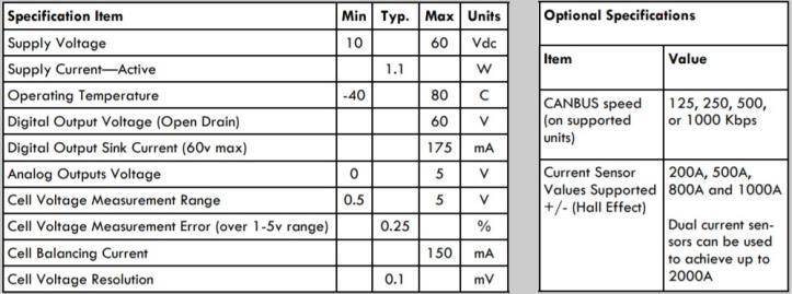
Battery Management System: Orion Jr 2 BMS
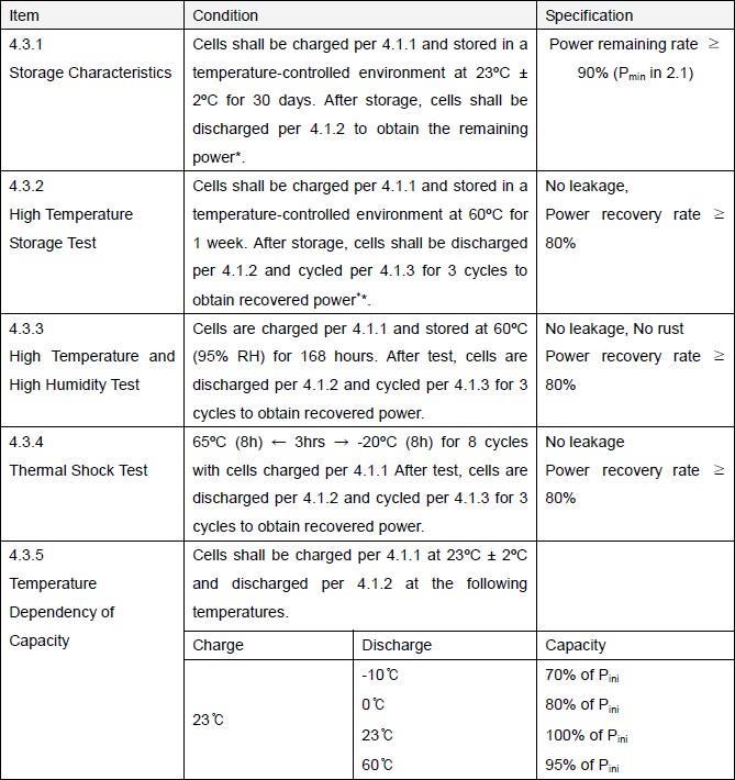
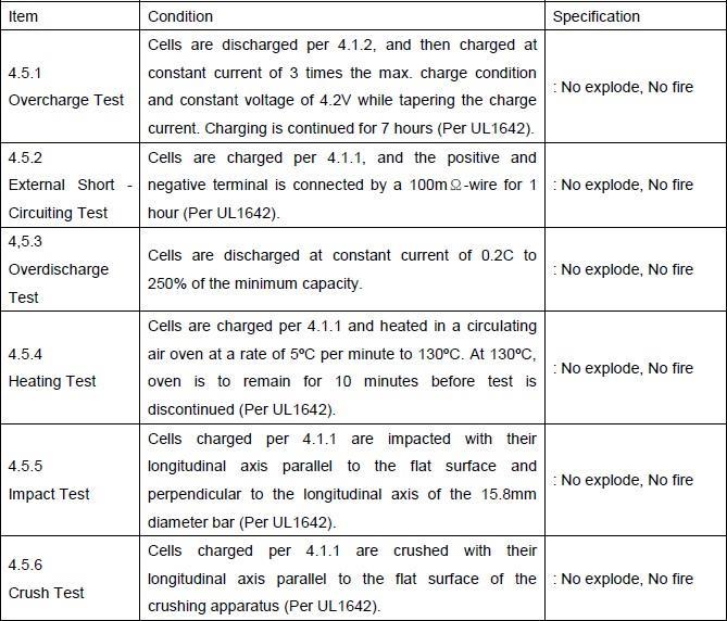
The Orion Jr. 2 BMS measures the battery temperature throughthreemainthermistorslinkedwithoutdelaytothe BMSwiththeoptionofextrathermistorsthruathermistor enlargement module. The BMS calculates the minimal, maximum,andaveragetemperaturesofthebatterypercent primarily based at the connected thermistors. These temperature readings are used in the calculation of most possiblefeeanddischargecurrentlimits,whichareusedto determinewhileandatwhatamperageabatteryp.C.Maybe chargedordischarged.Themulti purposeoutputsmaybe programmed to turn on or off at particular temperatures, whichcanbebeneficialinsomepackages.
International Research Journal of Engineering and Technology (IRJET) e ISSN: 2395 0056 Volume: 09 Issue: 01 | Jan 2022 www.irjet.net p ISSN: 2395 0072 © 2022, IRJET | Impact Factor value: 7.529 | ISO 9001:2008 Certified Journal | Page859 5.1.distinctThe5.fromwithcommunicateoverCAN,howmanycellsitcouldmonitorbothvoltageandtemperature,andwhetheritwasisolateditsvoltagetaps.CurrentLimitingviathedigitalCANBUSDataCollectionOrionJr.2BMScollectsinformationfromseveralsensorsforuseincalculationsanddecisionmaking.CellVoltages
Current sensor data is utilized in calculating the battery percent’s nation of charge (thru coulomb counting) and ensuring that the connected utility is staying inside the perfectcontemporarylimits.Themeasuredcurrentisalso utilizedincalculatingtheinnerresistanceandhealthofthe cellsinthebatterypercent.
Five.4. TotalPackVoltage
The BMS takes an wise method to balancing that seeks to hold and improve stability from cycle to cycle. Li ion batteriestendtoliveinstabilitynotliketheleadacidones. Differencesinselfdischargecosts,cellulartemperatureand internal resistance are the number one causes of an unbalancedbatteryp.C..TheBMSmustbecapableofaddor subtractchargefromthebottomormaximumcellstomake amendsforthedifferenceindischargechargestopreserve thecellsbalanced.
Five.3. Temperatures
The BMS has the potential to experiencethefameoftheCHARGEpowersupply.TheBMS usesthisinputtodeterminewhatmodetheBMSisin.The BMSadditionallyhasamulti purposeenterwhichmaybe used for diverse functions, which includes monitoring the popularityoftheREADYelectricitysupplyifessential.
The BMS measures battery temperatures immediately from up to 3 thermistors to determinetheaveragetemperatureofthebatterypercent.If additionaltemperature sensing, which include measuring the temperatureofeachcharactermobile,isrequired,theOrion Jr.2BMScanbelinkedtoathermistorgrowthmodulethat maypermitmeasuringupto80thermistors.Thermistorson boththemainunitandanyexpansionmodulescanbeleft ‘unpopulated’ meaning that the BMS will forget about the value of these thermistors. This permits the BMS to be configured to use as few or as many thermistors as important.Thethermistorgrowthmoduleisattachedtothe OrionJr.2BMSviatwooftheanalogthermistorinputsatthe BMSorviaCANBUSiftheBMSisCANenabled.
7. CellBalancing
TheOrionJr.BMSmakesuseofpassivebalancingtoremove ratefromthebestcellsinanefforttokeepthestabilityofthe %theusageofpassiveshuntresistors.
5.2. Current(Amperage) Thepresentdayenteringinto andout ofthe batterypercentismeasured every8msthe use of the external corridor effect sensor. The hall effect sensorisclampedaroundatwinecarryingallcutting edge into and out of the battery percent and converts the measured amperage into 0 5 volt analog voltages. One channelisusedformeasuringsmalleramperagestoensure highresolutionforsmallcurrentsandtheoppositechannel isusedformeasuringlargercurrents.These analogvoltages aremeasuredbywayoftheBMSandtransformedintoan amperagecostwhichtheBMSmakesuseoffornumerous Thecalculations.presentdaysensorssoldwiththeOrionJr.2BMSare available in sizes as much as 1000A. The BMS can be configuredtouse2parallelcutting edgesensorstomeasure amperagesupto2000A, butthemostadvocatedlength is 1000A.CurrentsensorsboughtwiththeBMSarecapableof degreeamperagesasmuchasonehundredtwenty%oftheir ratedmost,eventhoughaccuracyisreducedabove100%.
6. ThermalManagementandFanControl
Eachcellular’svoltageismeasured approximatelyevery30mS via sensingthevoltageonthe cellvoltagetapconnector.TheBMSmeasuresthedistinction involtagefromonetapwiretothesubsequenttomeasurea cellular's voltage. Unless busbar repayment has been configured,theBMSwilldisplayandusetheactualmeasured valuesforcellvoltages(otherwisecompensatedvaluesare used). Only the cellular voltages which the BMS has been programmedtomonitorinthemobilepopulacedeskinside the settings profile are monitored while the opposite cell voltagesareignored.
TheOrionJr.2BMSmeasures the overall percent voltage by summing up the individual cellularvoltages.
5.5. Other Inputs
[9] Affanni, A.; Bellini, A.; Franceschini, G.; Guglielmi, P.;Tassoni, C., “Battery choice and management fornew generation electric vehicles”, IEEE Trans. on Industrial Electronics,Vol.52(5),Oct.2005,pp.1343 1349.
TheMainAimofthispaperistolayoutaelectricpowered bikethatisefficientanditmustbesuitabletoIndianroads. In this paper we have researched approximately all the additivesthatdesiresinelectricbikewhichmakeitcapable ofgetpushedbyusingpersononroads.Wehavecompared numeroustirelengthappropriateandconcludedbywayof selecting one additionally on this paper we've got also researchedapproximatelysuspensionseatsandthewhole thingthiswasacompleteblueprintofaelectricvehiclethat wewant REFERENCES
TheBMShasasafetyfunctiontosaveyouover discharging cellduringbalancingin event
[5] Jinyun Gan; Chau, K.T.; Chan, C.C.; Jiang, J.Z., “A newsurface inset,permanent magnet,brushlessDCmotor driveforelectricvehicles”,IEEETransactionsonMagnetics, Vol.36,Issue5,Part2,Sept2000,pp.3810 3818.
[4] Haddoun, A.; Benbouzid, M. E. H.; Diallo, D.; Abdessemed,R.;Ghouili, J.; Srairi, K.,“A Loss Minimization DTCScheme for EV Induction Motors”, IEEE Trans onVehicularTechnology,Vol.56(1),Jan.2007,pp.81 88.
[7]2257.Rahman, K.M.; Fahimi, B.; Suresh, G.; Rajarathnam, A.V.;Ehsani, M., “Advantages of switched reluctance motorapplications to EV and HEV: design and control issues”,IEEE Transactions on Industry Applications, Vol. 36,Issue1,Jan. Feb.2000,pp.111 121. [8] Jones, W.D., “Putting Electricity Where The Rubber MeetstheRoad[NEWS]”,IEEESpectrum,Vol.44,Issue7,July 2007,pp.18 20.
[10] Chan, C.C. The Present Status and Future Trends of Electricvehicles,ScienceandTechnologyReview,Vol.23,No. 4,Feb2005 [11] Andrew Williams, “MIT Battery Breakthrough CouldRevolutionize Electric Cars”, March 12th, 2009 in Batteries, Electric Cars (EVs), http://gas2.org/2009/03/12/mit battery breakthrough could revolutionize electric cars/
[14]Chikhi,F.ElHadri,A.Cadiou,J.C.“ABScontrol design basedon wheel slippeak localization”.Proceedingsofthe FifthInternationalWorkshoponRobotMotionandControl, PublicationDate:23 25June2005,pp.73 77
[2] Jones, W.D., “Take this car and plug it [plug in hybrid vehicles]”,Spectrum,IEEE,Vol.42,Issue7,July2005,pp.10
any
[1] Jones, W.D., “Hybrids to the rescue [hybrid electric vehicles]”,IEEESpectrum,Vol.40(1),2003,pp.70 71.
[6] Chau, K.T.; Chan, C.C.; Chunhua Liu, “Overview ofPermanent Magnet Brushless Drives for Electric andHybrid Electric Vehicles”, IEEE Trans. on IndustrialElectronics,Vol.55,Issue6,June2008,pp.2246
[12] Y.Lu, Cheng K.W.E., S.L.Ho, J F Pan, “Passivity Based Control of Phase Shifted Resonant Converter”, IEEE Proc. Elect.PowerAppl.,Vol.152(6),Nov.2005,pp.1509 1515
TheOrionJr.BMShasannon compulsoryCAN(controller regionnetwork)interface.Theinterfacehasaprogrammable frequency (baud rate). The BMS capabilities up to 15 programmable CAN. These messages are designed to be bendy to interface with other digital manipulate gadgets, computer structures, shows, or any number of different devices. Virtually all BMS parameters are able to be transmittedinthoseCANmessages.Pleaseseethe“Editing CAN Messages'' section of the Software Utility guide for information on programming custom CAN messages. In a CANBUS community there are always precisely two terminator resistors. It is as much as the person to make certain that there is the proper quantity of terminator resistorsoneveryCANcommunity.Bydefault,theOrionJr. BMS has a terminator resistor already loaded at the CAN interface. The CAN interface can also be used to upload settings.Howev Conclusion
[3]13.Hyunjae Yoo; Seung Ki Sul; Yongho Park; Jongchan Jeong,“SystemIntegrationandPower FlowManagementfor aSeries Hybrid Electric Vehicle Using Supercapacitors andBatteries”, IEEE Trans. on Industry Applications, Vol. 44,Issue1,Jan. Feb.2008,pp.108 114.
the
International Research Journal of Engineering and Technology (IRJET) e ISSN: 2395 0056 Volume: 09 Issue: 01 | Jan 2022 www.irjet.net p ISSN: 2395 0072 © 2022, IRJET | Impact Factor value: 7.529 | ISO 9001:2008 Certified Journal | Page860
ofadefectiveordead 8.mobile CANBUS
[13] K.W.E.Cheng, “Tapped inductor for switched mode powerconverters”,2ndInt.ConferenceonPowerElectronics SystemsandApplications,2006,pp.14 20.