| ISO 9001:2008 Certified Journal | Page1
International Research Journal of Engineering and Technology (IRJET) e ISSN: 2395 0056 Volume: 09 Issue: 01 | Jan 2022 www.irjet.net p ISSN: 2395 0072 Indigenously Design Development and Motion Control of Multi-DoF Robotic Manipulator Muhammad Bilal1 , Muhammad Nadeem Akram2 1Human Centered Robotics Lab, National Centre of Robotics & Automation, University of Engineering & Technology, Lahore 54890, Pakistan 2Department of Mechanical, Automotive, and Materials Engineering, University of Windsor, Windsor, Ontario, Canada *** Abstract – A robotic manipulator needs to be compliant, efficient, and lightweight to carry out multiple operations with the desired accuracy in the industrial environment. These factors impose a great challenge to design, analyze, and implementation of control architecture on the sophisticated robotic system. In this pursuit, this study aims to indigenously design and control a six degree of freedom (DOF) robotic manipulator to perform demanded tasks. The mathematical expressions for the robot’s motion, including its kinematics and dynamics, have been derived and discussed in detail. Apart from that, the design analysis has been performed to figure out the mechanical system stability. Moreover, the workspace analysis has been carried out followed by a kinematics study using Robotics System Toolbox to ensure the authenticity of derived mathematical models. To validate the forward and inverse kinematics, the position control has been implemented on robotic manipulator hardware using ARM microcontrollers. The robotic manipulator has been controlled through Visual Studio GUI (Graphical User Interface). The transfer function of actual DC motors is estimated using the System Identification Toolbox after needful experimentations. A series of simulations followed by experiments are carried out to effectively validate the design and control architecture. The robot’s weight is calculated to be 5.98 Kg with a payload capacity is approximately 330 g. The repeatability test is performed which amounted to ±0.35cm.
© 2022, IRJET | Impact
Key Words: Robot design, robot kinematics, position control,pickandplace,systemidentification
1. INTRODUCTION
Nowadays, robots are utilized for multiple tasks, such as painting, polishing, spot welding, pick and place of heavy objects, and many other useful applications [1] [2]. In an industrial environment, robots perform multiple operations withdesiredaccuracyandprecisionwhichare unachievablebyhumanworkers.Todesignaroboticmanipulator, first of all, it is required to design a mechanical structure and then model its kinematics [3]. There are multiple fundamental configurations of robotic manipulators available includes articulated, cylindrical, spherical, etc. [4]. These robotic manipulators are used for different kinds of applications as mentioned earlier. As per the design perspective, it is required to select the material which has a high strength toweightratiotooptimizethemaximumpayloadcapacity of the robotic manipulator. The lighter the weight of the manipulatorthemoreloaditcanliftwiththeassuranceof Innotcompromisingonmaterialstrength.termsofthekinematicsstudy,multipleapproachesare utilized by researchers, including the screw based theory [5] and the Denavit Hartenberg convention [6]. These methods are shown identical results for direct kinematics [7]. The problem of kinematics is divided into two subgroups: 1) Forward Kinematics and 2) Inverse Kinematics [8]. The forward kinematics model of the 6 DoF robotic manipulator is described which is used for different applications [9][10]. Between forward and inverse kinematics, the inverse kinematics is more complexascomparedwiththeforwardkinematics[11].In the last decades, several researchers have worked on the kinematics formulation. For computing the joint variables of a robotic manipulator, a geometric model is presented [12]. The problem of direct kinematics is solved using quaternionalgebra[13].Basedontheforwardkinematics solution, the inverse kinematics model is presented to solve the joint variables of a serial robotic manipulator [14]. A sophisticated mathematical model of the SCARA robotic arm has been developed with actuator dynamics [15]. The inverse kinematics of the hydraulic arm is computed using MATLAB environment [16]. A virtual robotmodal ispresentedto solvethekinematicsproblem The[17].robotic arm has been controlled using an ARM based microcontroller, LabView, and Dexter ER2 Robotic arm [18]. The joint angles of 5 DoF are calculated and tested using a geometric approach [19]. As per the authors’ knowledge,nowork hasbeenreportedinthepast.Inthis paper, the author presented the kinematics of the 6 DoF robotic arm, including forward and inverse kinematics, with in depth details to ensure transparency. To validate the kinematics of the manipulator, the model is implemented using a MATLAB environment. The experimental setupto operate6 DOF robotic manipulator consists of three L298 motor drivers to send PWM and control the direction of actuators. The DC motors with incremental encoders and gear boxes are used as actuators in the robotic manipulator. Furthermore, a Factor 7.529
value:

7.529 | ISO 9001:2008 Certified Journal | Page2
Position kinematics deal with the relationship between joint variables, and task variables of the robotic manipulator. Kinematics plays an important role in a robot’s motion. It is further divided into sub groups: 1) Forwardkinematics,and2)Inversekinematics.
Amongthenumberofmaterials,aluminum7075ischosen based on high strength, less weight, corrosion resistance, and thermal conductivity. More precisely, it has less strengthtoweightratiowhichmakesitabetterchoicefor ourdesign.However,this material isexpensive,butithas moresuitablemechanicalpropertiescomparativeto6061 suchasitsyieldstrengthis73kpsiwhereas6061hasjust It40kpsi.isnotfeasibletouseahightorquemotorwithoutsucha mechanism to increase torque. Therefore, timing belt pulley is employed for motion transmission between motor,andjointshaft.Duetothelowloadonbase,elbow, andwristascomparedtoshoulder,GT2timingbelt pulley withratio1:2.08isemployed.Whilefortheshoulderjoint, theG3Ttimingbelt pulleysystemwitha ratioof1:3.57 is used to effectively hold the shoulder joint at extreme conditions. The thrust bearing is used at the base joint to shifttheaxial loadonthebasestructure.Whilethethrust bearing bears axial load but it cannot shift radial load, which is a limitation. On top of that, the thrust bearing providessmoothrotationwithnegligiblefriction.
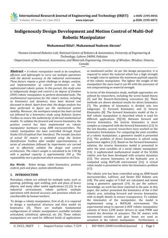
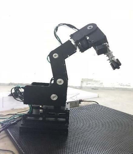
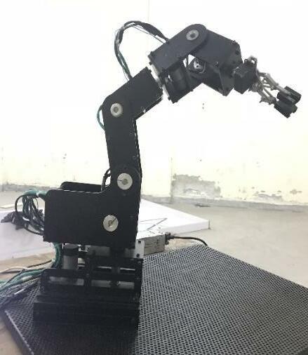
2.2.1 Forward Kinematics In forward kinematics, the end effector variables are calculated for the given pose (position plus orientation). There are two major methods available to calculate the forwardkinematicsofthen DOFrobotics manipulator: 1) Homogenous transformation and 2) Denavit Hartenberg (D H) convention. In the Denavit Hartenberg convention, there are four parameters used to derive the kinematics model of the robot. Among four parameters, one parameter is variable while the remaining three parametersareconstant.AccordingtotheD Hconvention, thetransformationmatrixofithjointw.r.ti 1jointcanbe representedasfollows: i otz, Transz, d Transx, a otx, (1) Tii [ ii ii ] (2) Tii [ ] (3) Where s , s , c and c indicate sin( ), sin( ), cos( ) and cos( ) respectively. While and depict the translation and rotation of i 1 joint w.r.t i joint. The D H parameters of the 6 DoF robotic manipulator are presented as shown in Table 1. Moreover, the frame of reference on each joint is represented as shown in figure 2. The joint limits are depicted as shown in Table 2. For thegivenjointvariables,theend effectorposew.r.tworld frameforn DoFcanbecalculatedasfollow: Figure 1: Mechanical design of 6 DoF robotic manipulator, including six servo DC motors, belt pulley mechanism to enhance torque, control unit, and functional gripper Factor value:
International Research Journal of Engineering and Technology (IRJET) e ISSN: 2395 0056 Volume: 09 Issue: 01 | Jan 2022 www.irjet.net p ISSN: 2395 0072 master, and slave topology is employed to ensure the efficient communication and coordination between controllers. A GUI (graphical user interface) is developed to have a user friendly experience to compute forward, and inverse kinematics. Moreover, a number of repeatabilitytestsareperformedtoevaluatetheprecision Theofmanipulatorbyperformingpick,andplacetask.restofthepaperisorganizedasfollows: the mechanical design, robot kinematics and dynamics, DC motor modelling, hardware description, and control scheme are discussed in section 2. After that, the simulations and results are presented in section 3 followed by experiments in section 4. In section 5, the conclusion followed by limitations and future work is presentedinsection6.
2.2 Position Kinematics
2. Methodology In this subsection, the mechanical design of the 6 DoF roboticmanipulatorisdiscussed.Thefirstthreejointsare in articulated configuration while the last three joints are standard spherical wrist. The mechanical design of the 6 DoF robotic manipulator with timing belt pulley mechanism and gripper attachment at end effector is showninfigure1.Inmechanicaldesign,materialselection is an important step due to weight, strength, machinability, manufacturability, and assembly easiness.
T T T T5 T5 [ ] (4)
© 2022, IRJET | Impact
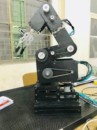

To derive the joint variables expressions for a 6 DoF robotic manipulator, the desired end effector pose can be expressedasfollow: T *r r r r r r r r r + (5) Usingeq.(5),thewristcenter xc, yc and zc canbecalculated as: xc x d r (6) yc y d r (7) zc z d r (8) Where x, y and z depict the end effector position while d6 indicate the link length between wrist center and end effector.Usingwristcenter,themathematical expressions forfirstthreejointscanbeexpressedas: ( ) (9) (√ ) (10) ( ( ( )) √ ( ) ) (11) (12) ( ( ) √ ( ) ) (13) Theterm l1, l2 and l3 indicatethebase,shoulder,andelbow link lengths, respectively. While 1, 2 and 3 represent first, second, and third revolute joints, respectively. Using these joint variables, the remaining spherical wrist angles 4, 5 and 6 canbecalculatedasfollow: (14) T (15) Where showrotationof 6th joint w.r.t 3rdjoint and rotation of 3rd joint frame w.r.t base joint frame, respectively.Bymatching withEulerrotationmatrix, [c c5c s s c c5c s s c s5 s c5c c s s c5c c s s c5 s5c s5c c5 ] (16) The singularity condition is occurred at . For nonsingular cases, the following expressions are derived forwristangles: atan r ,r (17) Table 1. Denavit Hartenberg parameters of 6 DoF robotic manipulator No.Link Alpha lengthLink offsetJoint Theta Offset 1 pi/2 0 L1 * 0 2 0 L2 0 * 0 3 pi/2 0 0 * pi/2 4 pi/2 0 L3 * pi/2 5 pi/2 0 0 * 0 6 0 0 L4 * 0 Table 2. Lower and upper limits of joint variables LimitsJoint Joint variables Articulated Manipulator Spherical Wrist J1 J2 J3 J4 J5 J6 Lower(deg) 45 0 0 90 90 90 Upper(deg) 45 80 60 90 90 90 Figure 2: Frame of Reference on each joint of 6 DoF robotic manipulator based on Denavit Hartenberg convention to demonstrate the transformation between joints © 2022, IRJET | Impact Factor value: 7.529 | ISO 9001:2008 Certified Journal | Page3
Ininversekinematics,thejointvariablesarecalculatedfor the given end effector pose. Fortunately, there is one widely used approach available to derive the joint variables expressions in terms of end effector pose provided the last three joints of robotic manipulator intersecting at a point. In case of 6 DoF robotic manipulator, most robots have decoupled configuration suchasthreeDoFsphericalwristattachedwiththreeDoF robot.Insuchscenario,the inversekinematicsproblem is resolved easily by splitting the problem into two subgroups: Inverse position kinematics and 2) Inverse orientationkinematics.
1)
International Research Journal of Engineering and Technology (IRJET) e ISSN: 2395 0056 Volume: 09 Issue: 01 | Jan 2022 www.irjet.net p ISSN: 2395 0072 2.2.1 Inverse Kinematics
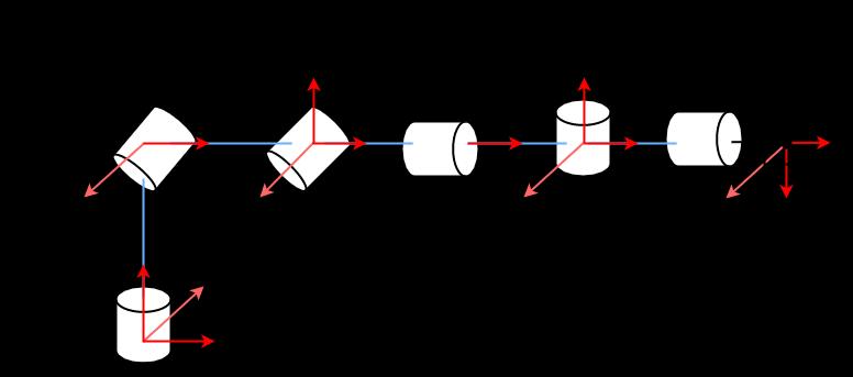

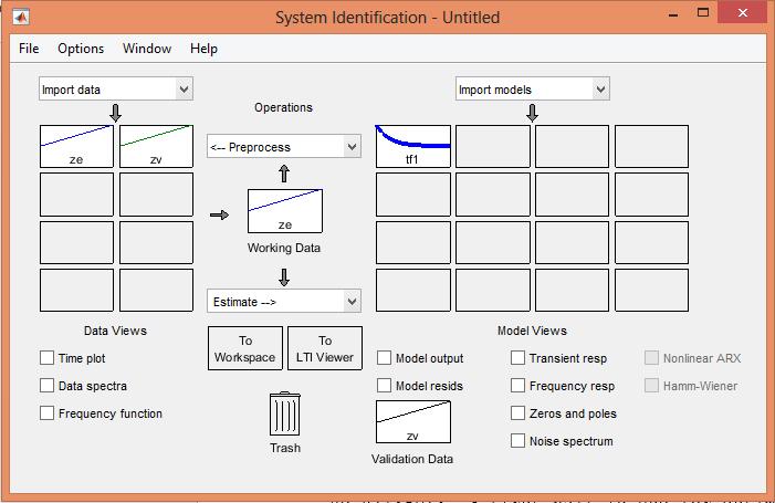
International Research Journal of Engineering and Technology (IRJET) e ISSN: 2395 0056 Volume: 09 Issue: 01 | Jan 2022 www.irjet.net p ISSN: 2395 0072 5 atan (√ r , r ) (18) atan r , r (19) ( ) (20) (√ ) (21) (( ( ( ))) √ ( ) ) (22) (23) (( ( ( ))) ((√ ) ( ( ))) ) (24) Supposethatboth r13 and r23 arezerothen, ( √ ) (25) ( ) (26) ( ) (27) Ifnotboth and arezero, >0.999and then, (29)(28) ( ) (30) Otherwise, ( ) (34) (√ ) (35) ( ) (36) 2.3 Robot Dynamics In robot dynamics, the mathematical expressions indicate the relationship between joint torques and joint accelerations. The inverse dynamics computes the joint torques for the given joint accelerations. While the forward dynamics calculate the joint acceleration for the given joint torques. There are two major methods availabletocomputetherobotdynamics:1)NewtonEuler and 2) Euler Lagrange. It is not possible to derive the explicit equation of motion with the Newton Euler formulation. For this reason, the equation of motion is derivedusingEuler Lagrangeformulationas: ( ) [ ] ( ) (37) ( ) ( ) ( ) ( ) (38) where, , =Jointposition,velocity,andacceleration ( )=Positive definiteinertialmatrix ( )=Gravitationalforces ( )=Frictionalforces ( ) =Coriolisandcentrifugalterms J=Jacobianmatrix =Externalforcesonend effector =jointtorques 2.4 DC Motor Modelling To design a PID controller, the transfer function of the motor is required to figure out PID parameters for the given desired transient response. Therefore, the transfer function of the DC motor is identified using System Identification Toolbox in MATLAB. An experiment is performed on each DC motor to compute the input, and output relationship by checking motor RPM with tachometer against multiple input voltages. This data is utilized in the System Identification Toolbox to find a transfer function as shown in figure 3. After that, the PID Tuner App is used for each transfer function to design a robust controller. The PID gains for each DC motor are listedinTable3. © 2022, IRJET | Impact Factor value: 7.529 | ISO 9001:2008 Certified Journal | Page4
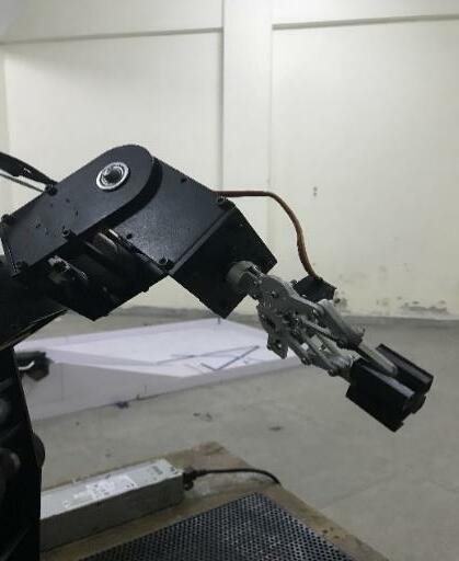
To ensure mechanical safety, the limit switches are mounted on each joint to stop the manipulator to avoid seriousinjury.Apartfromthat,thelimitswitchesareused for detecting home position as a power switch to ON. Moreover,theforcesensorismountedontheend effector tomeasureforce.
International Research Journal of Engineering and Technology (IRJET) e ISSN: 2395 0056 Volume: 09 Issue: 01 | Jan 2022 www.irjet.net p ISSN: 2395 0072 Table 3: PID gains of each motor mounted on 6 DoF robotic manipulator Motor Kp Kd Ki Base 100 400 0.00001 Shoulder 120 550 0.00006 Elbow 78 289 0.0009 Wrist 1 144 362 0.008 Wrist 2 206 199 0.0007 Wrist 3 165 183 0.0054 2.5 Hardware Descriptions 2.5.1 Controller To operate a robotic manipulator, the ARM based microcontroller Tiva C tm4c123gxl LaunchPad is employedduetoCortex M4F32 bitCPUoperatingat80to 120 MHz. There are two encoder modules available in a singleunit.Forsixactuators,threecontrollersareusedto measurepositiondatafromtheencoder.Themaster slave technique is used for controlling a 6 DoF robotic manipulator. 2.5.2 Actuators onfollowingrelationshipsystemtheproject,motorsandroboticThereareseveraltypesofactuatorsavailabletopropelthemanipulator,suchaselectricmotors,pneumatics,hydraulics.Amongalltypesofactuators,electricarewidelyusedinroboticmanipulators.InthisencodedDCmotorswithgearboxesareusedforactuationoftheroboticmanipulator.Abeltpulleyisusedtoincreasemotortorque.Tocomputethebetweenthemotorrotationandlinkshaft,thecalculationiscarriedoutforthemotormountedthebasejoint. Motor Gear ratio = 43.8:1 Pulley ratio = 2.08:1
Tofigureoutthegear ratiobetweenshaftandencoder, 43.8×2.08=91.104 After multiplication 91.04 with encoder resolution, the totalnumberofbitsare: 91.104×32=2915.328 bits 360 degree=2915.328
bits 1 bit=360/2915.328=0.1234852
To compute the exact position/angle of the shaft, this factorwill multiplywiththe currentencoderreading.The same calculations are carried out for the remaining five motorsasshowninTable4.
2.5.3 Sensory System
2.6 Control Architecture In this section, the control scheme is discussed in more detail. To validate the kinematics of the robotic manipulator, the position control scheme is implemented using a PID controller. As mentioned in the previous section, the PID gains are computed based on the estimated transfer function of the DC motor using MATLAB.ThePIDalgorithmcanbeexpressedas: Current error = desired value actual value; Integral error = (accumulator error) * time period; Derivative error = (Current error previous error) * 1/time period; PID = kp*Current error + ki*Integral error + kd * Derivative Previouserror; error = Current error; Accumulator error += Current error; Table 4: Motor specifications and pre computation of each motor mounted on 6 DoF robotic manipulator Motors RatioGear (Kg.cm)TorqueStall CurStallrent(A) RPM Res.(CPR)Encoder 1 bit = 1st 43.8:1 12 7 251 32 0.1234 2nd 270:1 80 6 40 32 0.0116 3rd 168:1 58 5 80 32 0.0324 4th 131:1 18 5 80 32 0.0858 5th 100:1 16 5 100 32 0.0540 6th 43.8:1 12 7 251 32 0.2568 Figure 3: System identification toolbox for identifying and validating DC motor transfer function © 2022, IRJET | Impact Factor value: 7.529 | ISO 9001:2008 Certified Journal | Page5
T [ . . 5 5
© 2022, IRJET | Impact Factor value: 7.529 | ISO 9001:2008 Certified Journal | Page6
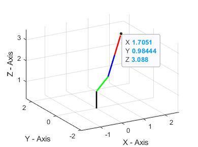
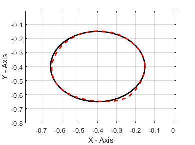
Figure 4: Implementation of inverse kinematics on 6 DoF robotic manipulator using MATLAB. The end effector position is represented as highlighted. Figure 6: Circular trajectory tracking. The solid black line indicates the reference path while the dark dashed line depicts the actual path of end effector
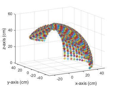
To verify the given pose against the computed joint variables, the forward kinematics is implemented to compute the end effector pose. The results show that the kinematics formulation is accurately derived as shown in figure 4. The calculated 4 by 4 homogenous transformations for the computed joint variables is expressedas: .5 .5 . 9 .85 Fortheexplorationofworkspace,theactuallinklengthsof 6 DoF robotic manipulator are considered as L1 = 13cm, L2 = 13.5cm, and L3 = 38cm. The workspace of the articulatedpartofthe6 DoFroboticmanipulatorbasedon
]
theallowablejointvariablesrangeisshowninfigure5. To further verify the kinematics formulation, the circular trajectoryisgiventotherobot withafixedorientation.In the first case, the link lengths are assumed to be the unit lengthofeachlink.Theresultsrepresentedthattherobot achieved the desired path with a minute error in the position due to computational error. Figure 6 shows the reference and actual path of the 6 DoF robotic manipulator.
International Research Journal of Engineering and Technology (IRJET) e ISSN: 2395 0056 Volume: 09 Issue: 01 | Jan 2022 www.irjet.net p ISSN: 2395 0072 3. Results & Discussion In this section, the simulation studies are discussed in detail to validate the kinematics expressions as well as to explore the workspace of the 6 DoF robotic manipulator. The link lengths are considered to be the unit length of givenfollowingeachlink.Toverifytheinversekinematicsformulation,the4by4homogenoustransformationmatrixistotherobottocomputethejointvariables. T [ . . 5 5 . 95 .9 9 . .5 . 9 .85 ]
. 88 .
4. Experiments
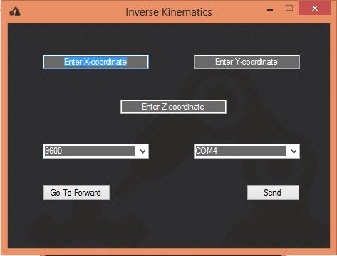
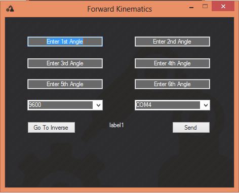
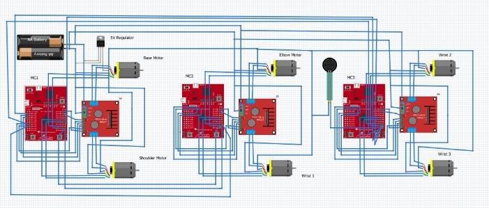
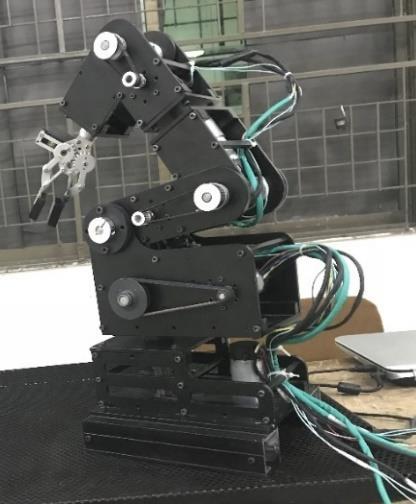
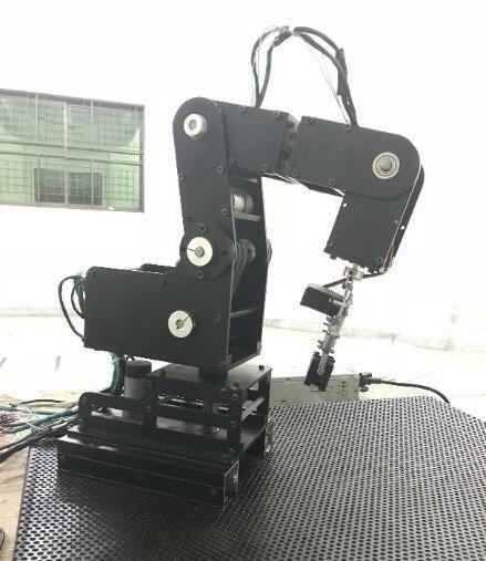
After validation of kinematics formulation, the position control using the PID controller is implemented onthehardware.Thecircuitdiagramtocontrolthe6 DoF robotic manipulator is shown in figure 9. There are three controllers used to control six encoded DC motors in which one controller act as a master and the remaining twocontrollersactasaslave.Moreover,threeL298motor drivers are used to control the PWM and direction of the DC motor. After that, the graphical user interface is designed to get data from the user and actuate the 6 DoF manipulator to achieve the desired pose. Figures 7 and 8 show the layout of the GUI for forward and inverse kinematics. A series of experiments are performed to effectively validate the design structure and control scheme. The joint actions of actual hardware are represented for each joint as shown in figure 10. The repeatability tests are performed which amounted to ±0.35cm. For the pick and place task, the gripper is controlled by a simple servo motor with a force sensor mountedbetweenthejawsofthegripper.
For the given pose, the joint variables are computed as presented: Joint variables (rad) = [0.5233;0.3927;0.6283;1.047;0;0.3490]


On the off chance that you have 6 DOF, a given end effector present is just reachable in a specific configuration of the robot. Unless provided that you have extra joints, you can in any case move the arm without moving the end effector so that for instance the elbow of the arm isn't slamming into parts of the workspace. So, a 7 DOF redundant manipulator will be used to reach the unreachablepointsoftheworkenvelope.Intheupcoming versionsofourrobot,wewillensurecylindricallinkshave an even load distribution in our design and improved aestheticsaswell.ThereplacementofBrushedDCmotors with Brushless DC motors will give us more control and precision to achieve our desired position and trajectory.
Figure 7: Inverse kinematics GUI layout to control the Figure 8: Forward Kinematics GUI layout to control the robotic manipulator
Figure 9: Circuit diagram to control a 6 DoF robotic manipulator, including six DC servo motors, three motor drivers, three ARM microcontrollers, power supply, and force sensor mounted on end effector
International Research Journal of Engineering and Technology (IRJET) e ISSN: 2395 0056 Volume: 09 Issue: 01 | Jan 2022 www.irjet.net p ISSN: 2395 0072
6. Limitations and Future Work
Above all that high resolution incremental optical encoders or absolute encoders would contribute to more Figure 5: Workspace analysis of 6 DoF robotic manipulator using MATLAB
Inthisstudy,theauthorsdesign,analyze,andfabricatethe 6 DoF robotic manipulator for pick and place operation. Moreover, the position control is implemented using an ARM based microcontroller to effectively validate the robot kinematics, including forward and inverse kinematics. The mathematical expressions for robot kinematicsarederivedandelaboratedinmoredetail.The transfer function of the DC motor is estimated using the System Identification Toolbox after collecting motor RPM data by applying a series of input voltages. To control a robotic manipulator, the graphical user interface is developedusingVisualStudio.Therobotpayloadcapacity isamountedto330gwhiletherobot’sweightis5.98Kg.A employedofnumberofexperimentsperformedtotesttherepeatabilitytherobotwhichcameout±0.35cm.Theforcesensorisontheendeffectortomeasuregrippingforce.
5. Conclusions
© 2022, IRJET | Impact Factor value: 7.529 | ISO 9001:2008 Certified Journal | Page7
International Research Journal of Engineering and Technology (IRJET) e ISSN: 2395 0056 Volume: 09 Issue: 01 | Jan 2022 www.irjet.net p ISSN: 2395 0072 precise feedback in a closed loop system. If we have enough cost for manufacturing, we can use Aluminum 7075 T6 instead of 6061 T6 to have more strength to weightratio. References
[5] S. A. Ajwad, M. I. Ullah, R. U. Islam, and J. Iqbal, “Modeling Robotic Arms A Review and DerivationofScrewTheory BasedKinematics,”no. January, 2014, [Online]. Available: content/uploads/2017/04/19https://192.169.156.207/wp 1.pdf.
[7] A. A. Mohammed and M. Sunar, “Kinematics modelingofa4 DOFroboticarm,”inProceedings 2015 International Conference on Control, Automation and Robotics, ICCAR 2015, 2015, pp. 87 91,doi:10.1109/ICCAR.2015.7166008. Home position Shoulder joint 60 degree Elbow joint 45 degree 1st wrist motor 45 degree Second wrist motor 45 degree Third wrist motor 45 degree Figure 10: Experimentations on 6 DoF robotic manipulator to ensure the validity of forward and inverse kinematics. 2022, IRJET | Impact Factor value: 7.529 ISO 9001:2008 Certified
Journal | Page8
[3] E. ELIOT, B. B. V. L. DEEPAK, D. R. PARHI, and J. SRINIVAS, “DESIGN & KINEMATIC ANALYSIS OF AN ARTICULATED ROBOTIC MANIPULATOR,” Int. J. Mech. Ind. Eng., pp. 12 15, 2014, doi: 10.47893/ijmie.2014.1177.
[2] M. Dahari and J. D. Tan, “Forward and inverse kinematics model for robotic welding process using KR 16KS KUKA robot,” 2011, doi: 10.1109/ICMSAO.2011.5775598.
[1] J. Liu and Q. Luo, “Modeling and Simulation of Robotic Arm in MATLAB for Industrial Applications,” Proc. 2019 11th Int. Conf. Intell. Human Machine Syst. Cybern. IHMSC 2019, vol. 1, pp. 346 349, 2019, doi: 10.1109/IHMSC.2019.00086.
[6] H. Lip in, “A note on Denavit Hartenberg notation in robotics,” in Proceedings of the ASME International Design Engineering Technical Conferences and Computers and Information in Engineering Conference DETC2005, 2005, vol. 7 B,pp.921 926,doi:10.1115/detc2005 85460.
[4] S. Kucu and . Bingul, “The inverse inematics solutions of industrial robot manipulators,” in Proceedings of the IEEE International Conference onMechatronics2004,ICM’04,2004,pp.274 279, doi:10.1109/icmech.2004.1364451.
©
|

[11] M. W. Spong, S. Hutchinson, and M. Vidyasagar, “Robot modeling and control,” IEEE Control Systems, vol. 26, no. 6. pp. 113 115, 2006, doi: 10.1109/MCS.2006.252815.
International Research Journal of Engineering and Technology (IRJET) e ISSN: 2395 0056 Volume: 09 Issue: 01 | Jan 2022 www.irjet.net p ISSN: 2395 0072
[8] T. P. Singh, P. Suresh, and S. Chandan, “Forward and Inverse Kinematic Analysis of Robotic Manipulators,” Int. Res. J. Eng. Technol., vol. 4, no. 2, pp. 1459 1469, 2017, Accessed: Nov. 28, 2021. [Online]. /IRJEThttps://www.academia.edu/download/52018593Available:V4I2286.pdf.
[12] K.E.ClothierandY.Shang,“AGeometricApproach forRoboticArmKinematicswithHardwareDesign, Electrical Design, and Implementation,” J. Robot., vol. 2010, pp. 1 10, 2010, doi: 10.1155/2010/984823.
[15] M. T. Das and L. C. Dülger, “Mathematical modelling, simulation and experimental verification of a scara robot,” Simul. Model. Pract. Theory, vol. 13, no. 3, pp. 257 271, 2005, doi: 10.1016/j.simpat.2004.11.004.
[16] K.KongandM.Tomizu a,“Controlofexos eletons inspired by fictitious gain in human model,” IEEE/ASME Trans.Mechatronics,vol.14,no.6,pp. 689 698, 2009, doi: 10.1109/TMECH.2009.2032685.
[17] R.Kumar,P.Kalra,andN.R.Pra ash,“AvirtualRV M1 robot system,” Robot. Comput. Integr. Manuf., vol. 27, no. 6, pp. 994 1000, 2011, doi: 10.1016/j.rcim.2011.05.003.
[18] C. C. Mouli, “Design and Implementation of Robot Arm Control Using LabVIEW and ARM Controller,” IOSR J. Electr. Electron. Eng., vol. 6, no. 5, pp. 80 84,2013,doi:10.9790/1676 0658084.
[10] N. Panigrahi and K. K. Dash, “Kinematic Model Design of a 6 DOF Industrial Robot,” in Applications of Robotics in Industry Using AdvancedMechanisms,2020,pp.203 212.
[19] K.E.ClothierandY.Shang,“AGeometricApproach forRoboticArmKinematicswithHardwareDesign, Electrical Design, and Implementation,” J. Robot., vol. 2010, pp. 1 10, 2010, doi: 10.1155/2010/984823. 2022, IRJET | Impact Factor value: 7.529 | ISO 9001:2008
[13] S. Sahu, B. B. Biswal, and B. Subudhi, “A Novel Method for Representing Robot Kinematics using Quaternion Theory,” IEEE Spons. Conf. Comput. Intell. Control Comput. Vis. Robot. Autom., pp. 76 82, 2008, Accessed: Nov. 28, 2021. [Online]. 89.http://dspace.nitrkl.ac.in/dspace/handle/2080/6Available:
Certified Journal | Page9
[14] S. N. Cubero, “Blind search inverse inematics for controlling all types of serial lin robot arms,” in Mechatronics and Machine Vision in Practice, SpringerBerlinHeidelberg,2008,pp.229 244.
©
[9] A. Khan and W. L. Quan, “Forward inematic modeling and analysis of 6 DOF underwater manipulator,” Proc. 2015 Int. Conf. Fluid Power Mechatronics, FPM 2015, pp. 1093 1096, 2015, doi:10.1109/FPM.2015.7337281.