International Research Journal of Engineering and Technology (IRJET)
e-ISSN: 2395-0056
Volume: 08 Issue: 09 | Sep 2021
p-ISSN: 2395-0072
www.irjet.net
COMPARATIVE STUDY ON THE DESIGN OF ELEVATED CIRCULAR CONCRETE WATER TANK Anjana M V1, Lakshmi Baliga2 1PG Student, Department of Civil Engineering, Shree Devi Institute Of Technology, Mangaluru, Karnataka ,India.
Assistant Professor, Department of Civil Engineering, Shree Devi Institute Of Technology, Mangaluru, Karnataka, India. ---------------------------------------------------------------------***---------------------------------------------------------------------2
Abstract - Water is an important things for all living beings
to live. In the area of scarcity of water it is very important to supply water. Water supply to that places are done by water stored in tank. This type of water tank are build publicly. Water stored in the tank are supplied through pipelines to the people. This tanks are of different shape like circular, rectangular etc.. It can be constructed at different height.In this project, elevated circular water tank are designed manually using limit state design method using codes( IS 3370-2009(part I-IV) ,IS 456-2000) and software design also done using ETABS. Finally compare both the results obtained from manually and software. At the end of the project it is noted that there is some reduction in the steel from the design of etabs compare to manual design.
1.1 OBJECTIVES The objectives of this study are listed below: 1. To compare the design of elevated circular water tank done by Manually and ETABS software in reference to IS 3370 Part I-IV, IS 456- 2000. 2. To study how much amount of steel required for the water tank. 3. To study the comparison between manual design and software design. 4. To study the design steps of different element of elevated circular water tank using limit state design method using IS codes (IS 3370 Part I-IV, IS 4562000).
Key Words: Elevated circular water tank, limit state method, ETABS.
1.INTRODUCTION A water tank is a structure which is used to store water Nowadays, the need of water tank are increasing. The water form the tank can be used for many purpose like house work, irrigation, fire safety etc.. The shape and size of a water tank are decided as per the capacities of tank. The cost and materials used for the water tank are decided according to the construction. Mostly, circular shape are more preferred for the water tank due to the uniform stress distribution. Design code used for the water tank design is IS 3370(Part IIV).
2. MATERIALS AND METHODOLOGY 2.1 MATERIALS PROPERTIES The grade of concrete is M30 and grade of steel is HYSD 415 for water tank construction.
2.2 METHODOLOGY In this project work elevated circular water tank is considered. Initially manual design are done using limit state design method as per code IS 3370:2009(part I-IV) and IS 456:2000, from the manual design the dimensions and area of steel are obtained. The water tank model were done in ETABS software based on the dimensions from manual design . Analysis was carried out for various components of water tank using ETABS software. The analysis were done by applying all the loads acting on the water tank. After the analysis software design and detailing were done. Finally compare both the design results which are obtained from software and manually.
Circular water tank are good for store large quantities of water and are economical. For elevated storage structure generally circular water tank are commonly employed. Generally, circular water tank with flat base are preferred which are more economical. The tank are generally supported on a ring beam and are supported on a number of columns. Normally, the diameter of ring beam is kept
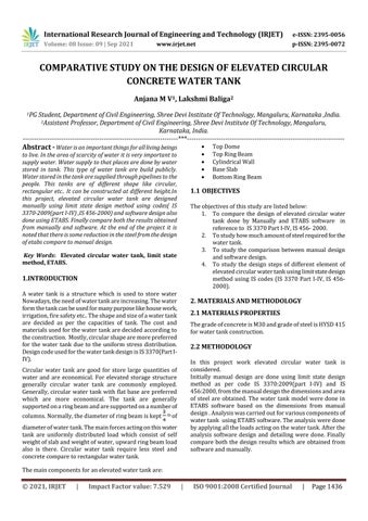
Top Dome Top Ring Beam Cylindrical Wall Base Slab Bottom Ring Beam
th of
diameter of water tank. The main forces acting on this water tank are uniformly distributed load which consist of self weight of slab and weight of water, upward ring beam load also is there. Circular water tank require less steel and concrete compare to rectangular water tank. The main components for an elevated water tank are:
© 2021, IRJET
|
Impact Factor value: 7.529
|
ISO 9001:2008 Certified Journal
|
Page 1436
International Research Journal of Engineering and Technology (IRJET)
e-ISSN: 2395-0056
Volume: 08 Issue: 09 | Sep 2021
p-ISSN: 2395-0072
www.irjet.net
3. DESIGN OF CIRCULAR WATER TANK
Cosθ = 0.724 Calculation For Loads (for 1 m length of dome) Length = 1 m Dead load = Width x Thickness x Density = 2.5 KN/m² Live load = Width x Live load (assuming live load = 1.5 KN/m²) = 1.5 KN/m² Total load (W) = 4 KN/m² Ultimate load = 1.5 x 4 = 6 KN/m2
The code used for the design are IS 1172(1993),IS:33702009(part II-IV) and IS 456-2000. In this study, for the design of water tank 4.5 lakh liter capacity is assumed.
3.1 Material M30 - Grade of Concrete Fe 415 - Grade of HYSD Reinforcement
3.2 PRELIMINARY DIMENSIONS
Stresses in Dome T1 = (W x R)/(1+cosθ) = 30.27 KN/m Meridonial Stress = T1/(b x t) = 0.302 N/mm² 0.302 N/mm² < σ cc = 8 N/mm² T2 = WxR[cosθ-1/(1+cosθ) ] = 8 KN/m Hoop Stress = T2/(b x t) = 0.08 N/mm² 0.08 N/mm² < σ cc = 8 N/mm² Stresses is within safe limits. As per IS:3370 (part 2 ) Table 2
Storage volume for 450000 liters = 450 m³ Volume of water tank , V = π x r² x h Assume height, h = 4 m 450 = π x r² x 4 r=6m D = 12 m By putting the value of h and r Volume = π x 6² x h = π x 6² x 4 = 450 m² Free board = 0.3 m Height of Staging from Ground = 10 m
Reinforcement in Dome The stresses are within safe limit. However provide minimum reinforcement of 0.24% area in each direction Ast = 0.24% x b x t = 240 mm² Using 8 mm ø bar, Aø = 50 mm² Spacing = 1000 x Aø/Ast = 208 mm Hence provide 8 mm ø bars @ 200 mm c/c in both directions.
3.3 PERMISSIBLE STRESSES As per IS:3370 (part II) Table 1, Table 2 and Table 4 σ cbc = 10 N/mm² σ cc = 8 N/mm² σ st = 130 N/mm² σ ct = 1.5 N/mm
3.6 DESIGN OF TOP RING BEAM
3.4 DESIGN CONSTANTS
It is designed for hoop tension W = T1cosθ = 22 KN/m
m=
Area of Reinforcement
Total hoop tension in beam = W x
= 9.33
K=
Ast =
= 0.42
= 132 KN
= 1015 mm²
Provide 12 mm ø @ 110 mm To find out Dimensions of Ring Beam
j = 1-( ) = 0.86
σ ct = R=
x K x σ cbc x j = 1.81
3.5 DESIGN OF TOP DOME
Ag = b x D Assume b = 250 mm
(i) Meridional Force(T1)
1.5 =
(ii) Hoop Tension(T2)
< 1.5
Thickness of Dome (assuming) = 100 mm
< 375 D + 12844
Central rise of dome (h1) = ( x diameter)= 2.4 m
<D
Radius of curvature (R) R² = (2r - rise) rise r = 8.7 m Semi Central Angle (θ) =
Consider D = 400 mm Size of beam = 250 mm x 400 mm Provide min. shear reinforcement 8 mm ø – 2 legged vertical stirrups From IS:456-2000, Page No – 48
= 43.60˚
Sv =
© 2021, IRJET
|
Impact Factor value: 7.529
|
= 362.96 mm
ISO 9001:2008 Certified Journal
|
Page 1437
International Research Journal of Engineering and Technology (IRJET)
e-ISSN: 2395-0056
Volume: 08 Issue: 09 | Sep 2021
p-ISSN: 2395-0072
www.irjet.net
Spacing limit (i) 0.75 x D = 0.75 x 400 = 300 mm (ii) 300 mm Adopt a ring beam of size 250 mm x 400 mm with 12 mm diameter as hoop reinforcement and 8 mm ø - 2 legged vertical stirrups @300 mm c/c.
Hence, it is safe
3.7 DESIGN OF TANK WALL
Spacing =
Area of steel for Bending Moment Ast(required) = Provide 12 mm ø bars
Thickness of wall T = 150 mm T = (30 H + 50 ) = 170 mm Take the value of T. i.e, T = 170 mm
=
= 188 mm
Provide 12 mm ø bar @ 170 mm c/c
3.8 DESIGN OF BASE SLAB
Assuming thickness of base slab as 350 mm. Outer diameter = 12 + 0.34 = 12.34 m
Design of Tank Wall for Hoop Tension
Load from Dome = T1 sinθ x 2π x
= 8
= 0.575 x 10 x 4 x 6 = 138 KN i.e, Maximum Hoop Tension occurs at 0.6 H = 0.6 x 4 = 2.4 m from the top
Self weight of slab = 0.35 x 25 = 8.75 KN/m² Total weight of slab = ( = 989.60 KN
Area of Steel for Tank Walls Ast(req) =
Finishing load = ( x 12²) x 0.6 = 67.86 KN
= 1061 mm²
Total load on slab = 5581.36 KN Ultimate load on slab = 5581.36 x 1.5 = 8372 KN Total upward force on Ring Beam = 2223 + 8372 = 10595 KN For the design of slab two cases are considered. (i) Circular slab simply supported and subjected to water pressure plus self weight of slab. (ii) Circular slab simply supported and subjected to upward ring load.
Minimum Steel, As Per IS:3370, Part II, Page No. 5 Ast(min) = = 408 mm² Provide 12 mm diameter bar Spacing =
=
= 107 mm
Provide 12 mm ø bar @ 100 mm c/c (As per IS:3370, Part II, Page No. 5) Check for Tensile Stress in Concrete Ast(provided) =
Calculation of B.M. and S.F. The radial and circumferential bending moments are calculated with the help of formulae given below. (i) B.M. due to U.D.L. p = 8372 KN Now, to convert p to U.D.L.
= 2260 mm²
σct =
= 0.73 N/mm²
Permissible tensile stress = 1.3 N/mm² (As per IS:3370, Part 2, Table 1) i.e, Actual tensile stress < Permissible stress Design is safe
= 74 KN/m² a = radius of slab =
Design of Tank Wall for Bending Moment As Per IS:3370, Part 4, Table 10 Coefficient = -0.0146 Bending Moment =
=
(Mr)c = +
= 72 mm
d(provided) = 170-25-12/2 = 139 mm > d(required)
|
Impact Factor value: 7.529
=6m
Normally, the diameter of supporting circle is kept 3/4 times the diameter of the tank. Diameter of beam = 9 m Radius of beam, b = 4.5 m
= 0.0146 x 10 x 4³ = 9.34 kNm Maximum Bending Moment = 9.34 kNm Check for effective depth d d(required) =
= 787 KN
Load from Ring Beam = (.25X .40) x π x 12 x 25 = 94 KN Load of wall = 0.170 x (4-0.3) x π x 12.17 x 25 = 601.22 KN Total circumferential load on the periphery of slab = 1482 KN Ultimate load on periphery of slab= 1482 x 1.5 =2223 KN Weight of water = ( = 4523.90 KN
As Per IS:3370 (part IV), Page No. 35, Table 9 Coefficient = 0.575 Hoop Tension =
© 2021, IRJET
= 601 mm²
|
pa² ; (Mr)e = 0
Mr =
p (a² - r²)
=
x 74(6² - r²)
ISO 9001:2008 Certified Journal
|
Page 1438
International Research Journal of Engineering and Technology (IRJET)
e-ISSN: 2395-0056
Volume: 08 Issue: 09 | Sep 2021
p-ISSN: 2395-0072
(Mθ)c = +
pa² ; (Mθ)e = +
www.irjet.net At Ring Beam (Mr)
pa²
Area of steel =
Mθ = +
(3a² - r² )
=
x (3(6)² - r²)
0 499.5 499.5
2.25 429.26 476.19
4.5 218.53 405.84
Spacing =
= 204 mm
Provide 12 mm ø @ 200 mm c/c
6 0 333
At Ring Beam (Mθ) Area of steel =
(ii) B.M. due to upward load W = 10595 KN For r ≤ b Mr = (Mr)b = Mθ = (Mθ)0 = -
] bd
= 552 mm² Using 12 mm diameter bars, Aø = 113 mm²
The values of Mθ and Mr at various locations are tabulated below r (m) Mr ( KNm) Mθ (KNm)
[1 -
[1 -
] bd
= 913 mm² Using 16 mm diameter bars, Aø = 201 mm²
[ 2 log ( )+ 1 – ( )² ]
Spacing =
For r > b
= 220 mm
Mr = -
[ 2 log ( ) - ( )² + ( )² ]
Provide 16 mm ø @ 210 mm c/c Provide min. steel at other remaining surface
Mθ = -
[2 log ( ) - ( )² + 2 - ( )² ]
Ast(min) =
x 1000 x 380 = 912 mm²
The values of Mθ and Mr at various locations are tabulated below
Spacing =
r (m) Mr ( KNm) Mθ (KNm)
3.10 DESIGN OF BOTTOM CIRCULAR BEAM
0 -289.77 -289.77
2.25 -289.77 -289.77
4.5 -289.77 -289.77
Povide 12 mm ø @ 115 c/c
6 0 -369
The tank is supported on a circular beam which in turn is supported on eight equally spaced columns. The diameter of supporting circle, upto the centre of the beam = 9 m. The total load W on the beam = 10595 KN. For the design of Bottom Ring Beam
(iii) Net Moments: The net moments will be the algebraic sum of the two, and are tabulated below r (m) Mr (KNm) Mθ (KNm)
0 209.73 209.73
2.25 139.5 186.42
4.5 -71.24 116.07
Super - imposed load on beam =
6 0 -36
-
=
-
= 374.72 KN/m
Assuming the beam to have a section of 1000 mm x 500 mm, Self Weight of Beam = 0.1 x 0.5 x 25 = 12.5 KN/m
The maximum shear force F=
= 123 mm
Total Weight , W = 374.72 + 12.5 = 387.5 KN/m
= - 208.22 KN
For θ,
3.9 DESIGN OF SLAB
2θ = (360˚)/n
The slab is to be designed for a maximum B.M. of 209.73 KNm. From B.M. point of view, d =
n=8
= 340 mm
2θ = 45˚= π/4
Let us keep total thickness =380 mm Using 20 mm ø bars, Provide d = 380 – 25 + 10 = 365 mm Effective depth d = 365 mm Area of steel =
[1 -
θ = 22.5˚ = C1 = 0.066 , C2 = 0.030 , C3 = 0.005, øm =
] bd
= 1702.06 mm² Using 20 mm diameter bars, Aø = 314 mm² Spacing =
Radius of beam =
= 184 mm
WR².2θ = 387.5 x 4.5² x( π/4 ) = 6163 KNm
Provide 20 mm ø @ 180 mm c/c
© 2021, IRJET
|
Impact Factor value: 7.529
= 4.5 m
|
ISO 9001:2008 Certified Journal
|
Page 1439
International Research Journal of Engineering and Technology (IRJET)
e-ISSN: 2395-0056
Volume: 08 Issue: 09 | Sep 2021
p-ISSN: 2395-0072
www.irjet.net Design of Mid- Span Section M = 184.89 KNm
Max. Negative Bending Moment at Support, Mn = C1 x WR²(2θ) = 406.75 KNm
Mu = 0.87 fy Ast d (
)
Max. Positive Bending Moment at mid-span, Mp = C2 x WR²(2θ) = 184.89 KNm Max. Torsional Moment at an angle of 9.5˚ from support, T = C3 x WR²(2θ) = 30.81 KNm
Ast = 544 mm² But min area of steel is 978 mm² Hence, adopt Ast = 978 mm² Using 16 mm ø bars (Aø = 201 mm²)
Max. Shear force at support, V =
No. of bars =
= 684.76 KN
Shear force at section of maximum torsional moment (øm = 9.5˚ = 0.1658 radians) is given by : VT = wR (θ-øm) = 387.5 x 4.5 ( = 395.65 KN
Provide 6 bars of 16 mm ø reinforcement Design of section subjected to Max. Torsional and Shear Equivalent Bending Moment Mel = Mu + Mt Mu = 0
Design of support section Mmax = 406.75 KN, D = 1000 mm , V = 684.76 KN Using 20 mm ø bars and a clear cover 35 mm , d = 1000 – 10 – 35 = 955 mm Min. depth required: Mu,lim = 0.36 x
(1 – 0.42
Mt = Tu
) bd² fck
Mt = 30.81 x
d = 443 mm Hence, provide deff = 955 mm Area of Steel required Mu = 0.87 fy Ast d (
Mt = 54.37 KNm Mel = 54.37 KNm Area of Reinforcement
)
Mu = 0.87 fy Ast d (
Ast = 1223 mm²
)
Ast = 158 mm² But Astmin = 978 mm² Hence, adopt Ast = 978 mm² Using 20 mm ø bars (Aø = 314 mm²)
Astmin = Astmin = 978 mm² No. of bars =
= 5 Nos.
=
= 4 Nos.
No. of bars =
Provide 3 bars of 20 mm ø reinforcement
Provide 4 bars of 20 mm ø reinforcement Astprovided = 1256 mm² Nominal shear strength (τv)
Transverse reinforcement Shear reinforcement Equivalent Shear
τv = τv = 1.4 N/mm² Compressive shear strength(τc) Percentage of reinforcement (p%) = 100
Ve = Vu + 1.6 Ve = 395 + 1.6 x
= 0.26
Ve = 493.6 KN
Thus, from table 19 IS 456:2000 τc = 0.3752 N/mm² τc < τv Thus, shear reinforcement is required Vus = Vu – τc bd Vus =684.76 – 0.3752 x 500 x 955 Vus = 505.76 KN
τv = τv = 1 N/mm² Percentage of reinforcement = 100
= 0.205
Thus, from table 19 IS 456:2000 τc = 0.334 N/mm² τv > τc Shear reinforcement is required Using 10 mm ø 2 – legged stirrups (Ast = 157 mm²) b1 = 500 - 35 -35 = 430 mm
Vus = Using 10 mm ø stirrups (2 – legged) Asv = 2 x x (10)² = 157 mm² Sv =
= 3 Nos.
= 107.03 mm ≈ 107 mm
Provide 10 mm ø 2 – legged stirrups @ 105 mm c/c
© 2021, IRJET
|
Impact Factor value: 7.529
|
ISO 9001:2008 Certified Journal
|
Page 1440
International Research Journal of Engineering and Technology (IRJET)
e-ISSN: 2395-0056
Volume: 08 Issue: 09 | Sep 2021
p-ISSN: 2395-0072
www.irjet.net
d1 = 1000 - 35-35 = 930 mm Asv =
the load acting on the tank and after that design were done. The project work is focused on the Comparative Study of circular overhead water tanks by manually and software. In both cases the dimensions of tank are same. The location considered for this project is Kannur, Kerala.
+
157 = [
+
] sv
Sv = 229 mm Check for spacing (i) x1 = 430 mm (ii)
Sl.No
=
= 340 mm
1 2 3 4 5
(iii) 300 mm Provide 10 mm ø 2 – legged stirrups @ 220 mm c/c Side face reinforcement ( As per IS 456 – 2000 ) As =
x 500 x 955 = 477 mm²
6 7
12 mm ø bars having , Aø = 113 mm² . No. of bars =
= 4.2
8
Provide 3 - 12 ø bars on each vertical face
9
3.11 MANUAL DESIGN RESULT DETAILS
10 11
Table – 1: Manual Design Result
SL. NO.
COMPONENTS OF WATER TANK
1 2 3 a b 4 a
Top Dome Top Ring Beam Tank Wall Hoop Reinforcement Bending Reinforcement Base Slab Reinforcement For Max. Bending Moment Reinforcement Of Radial Moment At Ring Beam Reinforcement Of Circumferential Moment At Ring Beam Bottom Ring Beam Support Section Mid-Span Section Maximum Torsion Transverse Reinforcement
b c 5 a b c d
12
MANUAL DESIGN
13 14 15
Ast in mm2 (Required) 240 mm2 1015 mm2
Table – 2: Water Tank Model Details Description Circular Elevated Water Tank Diameter of Column 800 mm No. of Column 8 Bottom Ring Beam 500 mm x 1000 mm Bracing 800 mm x 500 mm Height of Staging 10 m (m) Thickness of Slab 380 mm Diameter of Tank 12 m (m) Height of Tank Wall 4m (m) Thickness of Tank 170 mm Wall Top Ring Beam 250 mm x 400 mm Roof Slab Thickness 100 mm (Dome Shape) Center Height of 2.4 m Dome (m) Type of Soil Moderate Soil Unit Weights Concrete = 25 KN/m³ Material M30 Grade Concrete and Fe415
1061 mm2 601 mm2 1702 mm2 552 mm2 913 mm2
1223 mm2 978 mm2 978 mm2 685 mm2
4. MODEL DETAILS For the design of water tank we have to create a model first. The modeling was done in ETABS software. Once the modeling was completed with desired material and section properties the model were subjected to analysis based on
© 2021, IRJET
|
Impact Factor value: 7.529
Fig – 1: 3D Rendered Model
|
ISO 9001:2008 Certified Journal
|
Page 1441
International Research Journal of Engineering and Technology (IRJET)
e-ISSN: 2395-0056
Volume: 08 Issue: 09 | Sep 2021
p-ISSN: 2395-0072
www.irjet.net
4.1 LOADS ACTING ON THE WATER TANK 1.
2. 3.
4.
4.3 SOFTWARE DESIGN RESULT DETAILS
Dead load: Dead load means the load due to the materials of the construction. i.e, unit weight of material x dimension or diameter of a section. Unit weight of concrete is 25 Kn/m3. Live load: Load exerted by the living beings. In water tank load of water also consider as live load. Wind load: Wind load details as per IS: 875 (part I-III),for the design Basic wind speed (Vb) = 39m/sec Terrain factor = 3 windward coefficient = 0.8 Leeward coefficient = 0.5 risk coefficient k1= 1.06 topography k3=1 importance factor = 1 Earth quake load: Earth quake load as per IS:1893(part I-II), for the design Seismic Zone = III Zone factor = 0.16 Importance factor =1.5 Response reduction factor =1.8
Table-3: Software Design Result
SL. NO.
COMPONENTS OF WATER TANK
1 2 3 a b 4 a
Top Dome Top Ring Beam Tank Wall Hoop Reinforcement Bending Reinforcement Base Slab Reinforcement For Max. Bending Moment Reinforcement Of Radial Moment At Ring Beam Reinforcement Of Circumferential Moment At Ring Beam Bottom Ring Beam Support Section Mid-Span Section Maximum Torsion Transverse Reinforcement
b c 5 a b c d
4.2 STRESS DIAGRAM AFTER ANALYSIS
SOFTWARE DESIGN Ast in mm2 (Required) 200 mm2 983 mm2 942 mm2 495 mm2 1653 mm2 526 mm2 874 mm2
1163 mm2 935 mm2 935 mm2 628 mm2
5. RESULT AND DISCUSSION In this study, elevated circular water tank was first designed by manually using limit state design method as per IS 4562000 and IS 3370-2009(part I-IV) and then compare that results with ETABS software design results. Comparative result of elevated circular water tank
Fig-2: Absolute Maximum Stress Diagram Maximum absolute stress is 15.15 N/mm2.
© 2021, IRJET
|
Impact Factor value: 7.529
|
ISO 9001:2008 Certified Journal
|
Page 1442
International Research Journal of Engineering and Technology (IRJET)
e-ISSN: 2395-0056
Volume: 08 Issue: 09 | Sep 2021
p-ISSN: 2395-0072
www.irjet.net
Table-4: Comparison Result SL. NO.
COMPONENTS OF WATER TANK
1 2 3 a b
Top Dome Top Ring Beam Tank Wall Hoop Reinforcement Bending Reinforcement Base Slab Reinforcement For Max. Bending Moment Reinforcement Of Radial Moment At Ring Beam Reinforcement Of Circumferential Moment At Ring Beam Bottom Ring Beam Support Section Mid-Span Section Maximum Torsion Transverse Reinforcement
4 a b c 5 a b c d
MANUAL DESIGN Ast in mm2 (Required) 240 mm2 1015 mm2
SOFTWARE DESIGN Ast in mm2 (Required) 200 mm2 983 mm2
1061 mm2 601 mm2
942 mm2 495 mm2
1702 mm2
1653 mm2
552 mm2
526 mm2
913 mm2
874 mm2
1223 mm2 978 mm2 978 mm2 685 mm2
1163 mm2 935 mm2 935 mm2 628 mm2
The total steel required from software design is 9334 mm2 and manual design is 9948 mm2. While comparing with manual design software design saves 10% of steel in whole structure. Manual design method require more time and complicated. Whereas the design done in etabs software require less time.
REFERENCES [1] [2]
[3]
[4]
[5]
[6]
[7] [8]
Code Books: IS 456-2000 and IS 3370-2009(part I-IV) . Dr. Ramakrishna Hegde, et al.,[2018]: “Comparative Study On Rectangular And Circular Water Tank Using Staad Pro Software”. International Research Journal of Engineering and Technology (IRJET), Volume: 05 Issue: 11 ,2018,ISSN: 2395-0056, ISSN: 2395-0056,ISSN: 23950072. Himanshu Dwivedi, et al.,[2019]: “Analysis And Design Of Water Tank Employing Staad. Pro For Cost Optimization”. International Journal of Scientific Research and Engineering Development,Volume 2, Issue 4, ISSN : 2581-7175. I.R. Saudagar, et al., [2019]: “Study On Comparison Analysis Of Circular And Intze Water Tank On Sloping Ground”. International Research Journal of Engineering and Technology (IRJET), Oct 2019, Volume: 06 ,Issue: 10, ISSN: 2395-0056, ISSN: 2395-0072 Rashadus Sadain, et al.,: “Comparative Analysis and Design of ESR by Manual and Software”.IOSR Journal of Engineering. Tejaswini R, et al.,,[2020]: “Design And Analysis Of Elevated Water Tank”. International Research Journal of Engineering and Technology (IRJET), Volume: 07, Issue: 08 ,ISSN: 2395-0056,ISSN: 2395-0072. Text Book: Design of R.C.C structure, by the author B.C. Punmia Urmila Ronad, Raghu K.S, et al.,[2016]: “Seismic Analysis Of Circular Elevated Tank”. International Research Journal of Engineering and Technology (IRJET), , Volume: 03, Issue: 09, ISSN: 2395 -0056, ISSN: 23950072.
Chart-1: Steel Distribution
6. CONCLUSIONS In this project a study is made to compare the design of elevated circular water tank by manual method and software method. To know about the area of steel required for the water tank. From the study it is finally conclude that. The amount of steel required for the whole structure is less for software design compare to manual design.
© 2021, IRJET
|
Impact Factor value: 7.529
|
ISO 9001:2008 Certified Journal
|
Page 1443