12 minute read
From the Various experiments & CFD analysis, we used dimensional values of iteration


Volume: 08 Issue: 09 | Sep 2021 www.irjet.net p-ISSN: 2395-0072
2. Throttle:
Advertisement
The first instrument that is used in the intake assembly that is mounted to the restrictor is the throttle body. For the engine KTM RC 390 we had two possibly compatible throttle bodies, one is the KTM RC 200 throttle body (dia 35mm) and the other is the KTM RC 390 throttle body (dia 46mm).
As calculated earlier, mass flow rate= 0.0703 kg/s.
For the Stock Throttle Body of KTM 390, inlet diameter distock= 46 mm.
Therefore, using the same formula of choked flow equation, saturation for air intake capacity for stock Throttle body= mstock= 0.3917 kg/s
Therefore, m/mstock= 17.9% i.e., the Restrictor gets saturated at less than 20% supply capacity of stock throttle body, which makes the throttle position beyond the 20% open capacity redundant.
Thus, we have selected a comparatively smaller throttle body of KTM RC 200 to increase the throttle response for the restrictor constraint.
For the Throttle Body of KTM RC 200, inlet diameter di200= 35 mm.
mi-200= 0.2268 kg/s.
Accordingly, m/ mi-200=31%. Also, the choking condition assumes the flow velocity equal to velocity of sound however, the actual intake velocity would be as low as 22m/s. Thus, at the operating conditions we have adequately increased the throttle response by replacing the throttle body upstream of restrictor.
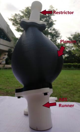
3. Plenum 4. Runner
An intake runner is a cylindrical pipe which connects the plenum to the inlet valves of the engine. The runner can have varying diameter and length. The runner not only helps in transporting the air from the plenum to the intake port but also helps in tuning the engine to give power in a desired RPM range. Long and narrow runners can be tuned to achieve low-end torque whereas short and wide runners can be tuned to achieve high-end horsepower. Therefore, the length and diameter of the runner play a key role in determining which rpm it will benefit. The air travels as pressure waves that travel from plenum to the intake valves, when the inlet valves open during the suction stroke of the engine the air waves rush into the combustion chamber and when the valves are closed after the suction stroke the air waves reflect back towards the plenum, these reflected waves are the negative pressure waves when these waves reach near the plenum it meets with a new boundary which reflects them back towards the engine port, since the valves are closed the waves are again reflected back. Thus, this creates a series of compression and decompression forming an acoustic wave. By tuning the runner length such that the pressure waves reach the valves at the exact time of the suction stroke at a specific rpm it can serve a purpose like a natural turbocharger.
4.1. Calculation and Analysis:
The intake manifold/plenum, is one of the biggest and important part of the intake system. It helps in storing and providing ready to use air to the engine during the suction stroke. The intake manifold also helps to recover the pressure losses at the venturi and stores volume of air according to the engine volume and acts as an environment for the suction of air during the intake stroke. The map sensor is mounted on the plenum which gives command to the fuel injector; thus, a good optimized plenum helps in more airflow and thus more fuel to the engine. As a rule of thumb observed in most of the papers, the plenum must be at least 2.5 to 3 times the engine capacity. We have selected 4 times the engine capacity as it is observed that at higher speeds higher volume of plenum improves the engine performance. The conventional plenums used normally are simple spherical shaped, cylindrical shaped or a log shaped. We observed that the log shaped plenum helped in providing a good streamline flow whereas the spherical shape gave less vortex formation, thus we created a mesh of spherical and log shaped plenum in order to achieve both the advantage and also to fit in the packaging of the vehicle.
As the plenum has a complicated shape and is a big part, we manufactured it by rapid prototyping with PLA material in order to achieve lighter weight and accurate design. The plenum can beseen in black color in figure:9.
The runner length is calculated using the Induction wave theory: -
L = (EVCD*0.25*V*2) / (rpm*RV) –0.5*D
Where:
EVCD = Effective valve closed duration
V = speed of sound, ft/s
Rpm = Revolutions per minute
RV = Reflective value
D = Runner Diameter =42mm = 1.653 inches (same as the engine inlet port)
ECD = Effective cam duration
Volume: 08 Issue: 09 | Sep 2021 www.irjet.net p-ISSN: 2395-0072
In the KTM RC 390 engine the Intake valves opens 2 degrees Before Top Dead Centre (BTDC) and Intake valves closes 44 degrees After Top Dead Centre (ATDC)
ECD = 180°+2°+44°=226° 4 stroke = 720°
EVCD = 720°-ECD-30° = 720°-226°-30° = 464°
Therefore, from the formula the Length of runner = (464*0.25*1125*2) / (7000*4) – 0.5*1.653 =8.49 inches =215.79mm.
Our engine istuned at stock settings of 7000 rpm and The RV value is taken 4.
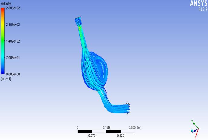
Therefore, the Runner Length we obtained is 215.79mm, the bending angle of the runner is 119 degree which is chosen according to the flow analysis and the packaging requirement. The velocity flow analysis of the entire intakesystem (restrictor, plenum and runner) is shown in fig: 4. Though, the flow indicates slight vortex in the plenum, the overall performance was not affected during the testing of the car.
Fig 4: Intake Flow Analysis
B. Exhaust:
An exhaust system is usually a pipeused to guide reaction exhaust gases away from the exhaust valve to the atmosphere. The entire system conveys burnt gases from the engine and consists of header pipe and a muffler which helps toattenuate the noise.
1. Header pipe:
It is bend pipe which provides the passage to the exhaust gas flow. For an effective exhaust system, header length and diameter must be design or optimized for higher scavenging efficiency with minimumbackpressure so as to avoid slow flow rate and discharge.
1.1. Header length of exhaust
The Header Length of exhaust can be calculated using the FormulaL = (129540 x E.T) / (R.P.M. x 6)
where, L = primary header length.
E.T = Exhaust Valve timing = 226 deg
R.P.M. = Estimated revs (Peak Power rpm)= 8100rpm
Estimated Length = 602.38 mm
1.2. Header pipe Diameter:
Choosing stainless steel, Thermal conductivity K=25.8 at 1000 ℃, (As discuss in section 4.1 manufacturing) and due to KTM engine mounting
O.D = 38mm
I.D = 34mm is choose to avoid any abrupt change in area.
For a good flow, exhaust pipes should be straight but due to engine mounting and space constrains into the chassis frame, bending of possibly large radii has to be design.
1.3 Simulation:
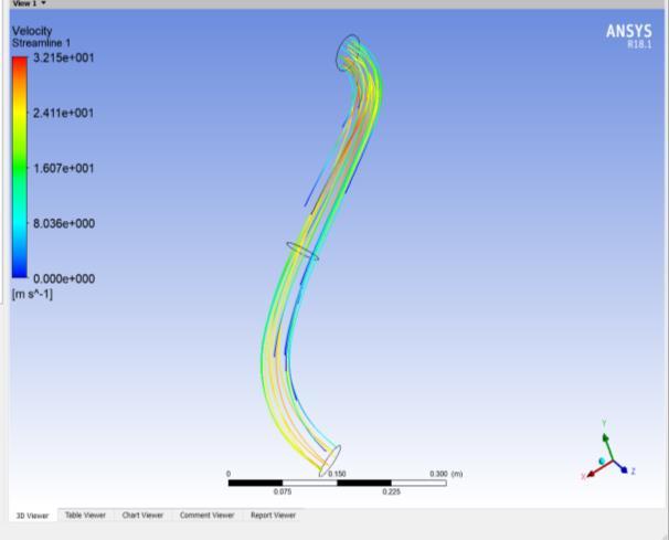
Various CAD designs of the exhaust pipes with varying length, bend radius, and diameter were analyzed using Ansys Fluent software to check the flow velocity and pressure contours. After performing simulations on various iterations following design was selected due to its flowtype,velocity and minimum back pressure in its bend.
Boundary conditionapply are
Inlet Pressure = 600 Pa (Gauge Pressure)
Outlet Pressure = Atmospheric pressure
Fig 5: Flow simulation (Velocity)
Volume: 08 Issue: 09 | Sep 2021 www.irjet.net p-ISSN: 2395-0072
Using Ansys Fluent software Flow Simulation was conductedand following result was achieved.
1. Flow with less turbulence 2. Higher flow velocity which leads to higher scavenging.
Fig 6: Exhaust assembly (without resonator)
The design as shown in fig.6 is the finalized cad model after performing the flow analysisas shownfig.5.
2. MUFFLER:
The main application of muffler is to reduce the loudness of the sound pressure, created due to burning of hot exhaust gas exiting the engine, by acoustic quieting. Among the two types viz. reflective and absorptive, absorptive muffler uses absorptive material such as glass wool to convert acoustic energy into heat energy.
In our case, we have used an absorptive type KTM stock muffler with baffles as it is less complex and reduces backpressuremorecomparedtothereflective type.
3. HELMHOLTZ RESONATOR:
For attenuating the sound, Helmholtz resonator was used. It is an apparatus able to pick out specific frequencies from a complex sound. The Helmholtz resonator consists of a rigid container of a known volume, with a small neck and hole in one end and a larger hole in the other end to emit the sound. Exhaust system frequency can vary between 50-400 hz and are calculated for the range of engine speed as shown in table 2. Engine Speed (rpm) Primary frequency(Hz)
6000 50
7000
8000 58.33
66.67
8500
9000 70.83
75
Table 2: Engine Frequency Calculation
The resonator dimensions as in Fig: 7 are calculated so that the waves reflected by the resonator help cancel out certain frequencies of sound in the exhaust. The natural frequency given by the following formula,
= (C÷2π )*√( (A/(V*l) )
Where, C = speed of sound
A= Area of neck
l= Length of neck
V= Volume of cylindrical cavity.
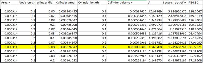
The following table in the fig 7 shows the no of iterations conducted for optimum frequency.
Fig 7:Resonant Frequency Calculation
The calculated resonant frequency was 68.22 Hz for below values,
A=0.000314 m2; l =0.2m;V=0.0015079 m3
IV. Manufacturing
A) Intake System:
The DeLaval nozzle and the Plenum (Fig: 9) are manufactured using rapid prototyping with PLA material. Rapid prototyping is used as it helped immensely in weight reduction over aluminum and helped in achieving the complicated shapes accurately.
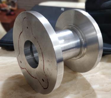
The runner was manufactured in two parts, one part towards plenum is manufactured by rapid prototyping with ABS material and the other part towards the engine port is made up of Aluminum (Fig 10). The part one is
Volume: 08 Issue: 09 | Sep 2021 www.irjet.net p-ISSN: 2395-0072
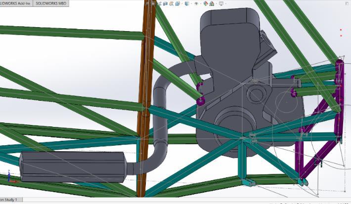
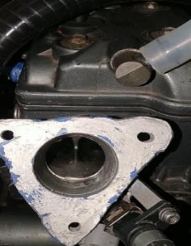
manufactured by rapid prototyping as it helped in weight reduction and achieving smooth bend, whereas the part two is manufactured by machining process using aluminum material as this part will have the fuel injector fitted, we needed to weld the aluminum casing of the fuel injector by manually testing the injector angle such that the fuel strikes exactly on the port(fig:8) also sinceABS is susceptible to chemical degradation due to petrol we avoided rapid prototyping the second part.
Fig 8: Manually adjusting the injector position
Fig 9: 3D printed parts assembly Fig 10: Aluminum runner before grinding
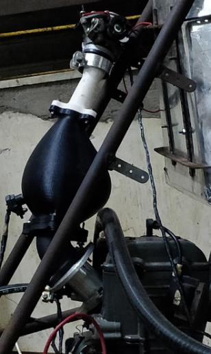
Fig 11: Full intake system assembly
B) Exhaust System
1. Material selection:
The main requirements of a material for an exhaust pipe are:
High service temperature High fatigue strength High fracture toughness High heat resistant Good machinability Good weldability Robust Thermal conductivity
Volume: 08 Issue: 09 | Sep 2021 www.irjet.net p-ISSN: 2395-0072
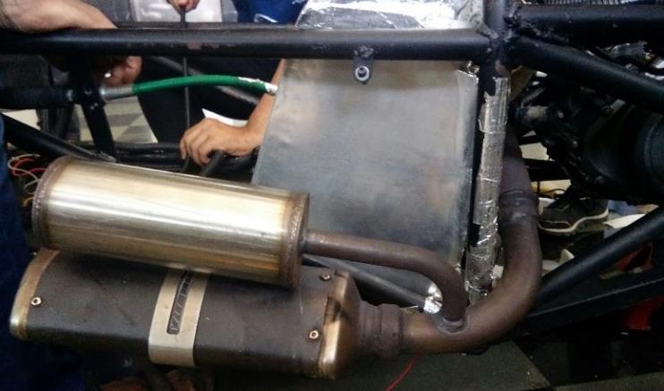
Fig 12: Exhaust with Resonator
Following table shows the available material for exhaust header pipe.
Material Name Cost
Titanium High
Mild steel Low Weight
Light
Heavy
Stainless Steel Moderate Moderate
Table-3
Material selected for exhaust header is Stainless Steel of grade 304 (Seamless) over Mild carbon Steel due its low corrosive resistance.
2. Manufacturing process:
The exhaust pipe was bended by NC bending process and welded to the muffler. Argon welding was done for preventing the formation of holes due to welding process. A flange is fastened with bolts to the exhaust port of engine.
V. CONCLUSIONS:
The designing, analysis and manufacturing was successfully achieved and tested on the car for the intake and exhaust system. The intake system was designed such that to be optimized it to have reduced pressure loss and constant ready to use air for the engine by an air-box. One of the problem faced by the intake system which affected the engine performance was minor air leakages whichwas solved by using a sealant.
The packaging of exhaust system has met the requirements with minimum bends, thus less backpressure. The exhaust has been tested successfully with accepted noise level.
VI. REFERENCES
[1] Omkar Deshpande1, Nitin L. Narappanawar2 “Space Advantage Provided by De-Laval Nozzle and Bell Nozzle over Venturi” Vol II WCE 2015.
[2] Arbaaz Sayyed, “Air Flow Optimization through an Intake System for a Single Cylinder Formula Student (FSAE) Race Car” IJERT Vol. 6 Issue 01. [3] Joel Jose1, Nishad Shetty2 “CFD Analysis of Air Intake Manifold System to Improve Efficiency of Formula SAE Car”, IOSR-JMCE Volume 15, Issue 2 Ver. IV.
[4] S S Sawant1 P N Gurav2, “DesignAnd Fabrication of Air Intake for FSAE Race Car” National conference on Changing Technology and Rural Development -2017
[5] Pranav Anil Shinde, “Research and optimization of intake restrictor for Formula SAE car engine” IJSRP Volume 4, Issue 4.
[6] Rahul Puri1, Harshal Darade2 “Design and Analysis of Intake and Exhaust System of SAE Supra Race Car”. IRJET Vol.03 Issue: 06 June-2016
[7] Vaibhav Sharma1, Sachin Hittalamane2 ,Exhaust Header Designing for Formula SAE
Car Vaibhav Sharma1, Sachin Hittalamane2 IJIRSET Vol. 6, Issue 9, September 2017
[8] Shubhamkumar Mangukiya1 Mr. Ripen Shah2 , ”Enhancing The Performance Of Single Cylinder Motorcycle Engine For Formula Student Vehicle By Optimizing Intake And Exhaust System”, JETIR Volume 5, Issue
[9] Mr. Damien Kennedy1 Dr. Gerry Woods2,“Development Of A New Air Intake And Exhaust System For A Single Seat Race Car” ITRN 2011.
[10] Sushil Pant1, Pankaj Kumar2 ,”Design and Analysis of Air Intake System for Single Cylinder Engine” IJTSRD Volume -2 Issue –2
[11] GRC NASA - https://www.grc.nasa.gov/www/k12/rocket/mflchk.html
Volume: 08 Issue: 09 | Sep 2021 www.irjet.net p-ISSN: 2395-0072
VII. BIOGRAPHIES
Siddhant Pawar
The author is an undergraduate student in the department of Mechanical Engineering at RGIT Mumbai, and the Design Head EngineeroftheIntake department in Team RGIT Racing.
Yogesh Kanade
The author is an undergraduate student in the department of Mechanical Engineering at RGIT Mumbai, and Design Head of the Exhaust department in Team RGIT Racing.
